WHY YOU SHOULD USE TUFFLOOR. components
|
|
|
- Virginia Campbell
- 6 years ago
- Views:
Transcription


1 Tuffloor DESIGN GUIDE

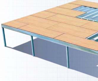
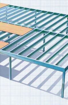
2 WHY YOU SHOULD USE TUFFLOOR Strong and Easily Installed Tuffloor is a steel floor framing system designed for strength and ease of installation, and is an easy and economical alternative to timber subfloors. The system is ideal for domestic house construction and extensions, and suits cladding with either tongue and grooved strip flooring, or a wide range of particleboard, and composite products. It is suitable for commercial and light industrial applications, although you should refer these applications to Stratco to determine allowable spans for these load conditions. Tuffloor is pre-cut to length, eliminating on-site cutting, saving you time and effort. Suits Your Project It is particularly suited for use with reactive soils, and sloping sites, and can be installed in remote locations without the need for cartage of extensive installation infrastructure. Offering economical spanning performance, Stratco Tuffloor is adaptable to a variety of building designs and construction methods. Economical All major structural components are made from high tensile steel providing strength and impact resistance. The efficient strength to weight ratio of high tensile steel minimizes the weight of materials needed to be transported to site, saving money in remote locations. With the increased load bearing capacity of the Tuffloor system, smaller sections can be used, contributing to cost efficiency. When this is combined with in-line construction, the total height of the building can be reduced, further saving brick and cladding costs. Keeping project costs under control is always a challenge on any building project and choosing Tuffloor for your project makes a lot of sense. Versatile 235mm sections allow for 115mm pipe penetrations and toilet bends under the floor, and standard joist spacings compatible with a large variety of flooring materials. Long Life The galvanised coating offers long term protection against corrosion. As the subfloor is made from steel it is not subject to twisting or warping. Other benefits include termite protection, mould resistance and elimination of wood rot. components 6mm 6mm 6mm 12mm 1mm mm, 235mm 187mm, 24mm 18mm, 23mm 18mm, 23mm 18mm, 23mm JOIST BEARER JOIST AngLE BRAckET 1.6mm galvanised BEARER AngLE BRAckET 1.6mm galvanised WEB STREngTHEnIng BRAckET Sectional Properties All sections are galvanised to Z35 specifications and are rolled out of high tensile material with a minimum yield Strength of 45MPa. JOIST Section Depth mm Width mm Lip mm Thickness mm Mass kg/m FJO W FJO D T FJO19 FJO L FJO235 FJO FJO BEARER Section Depth mm Width mm Lip mm Thickness mm Mass kg/m D W T FBE19 FBE24 FBE FBE Table 1.
3 Design criteria Stratco Tuffloor flooring conforms with the following Australian standards: AS 41:1998 Steel Structures. AS/NZS 46:1996 Cold-formed Steel Structures. AS/NZS 117:22 Structural Design Actions. AS 3623:1993 Domestic Metal Framing. Stratco Tuffloor Flooring complies with the static and dynamic response requirements imposed by AS Domestic Metal Framing. The maximum serviceability deflection of the floor is limited to L/36 but kept to less than a maximum of 12mm. The Roof Load Width is the effective width of roof that the bearer is supporting. Figure 1. shows a simplified method for determining the Roof Load Width. Refer to Stratco for load conditions and spans outside the limits of these tables. Footings, columns, bracing and the tie down should be designed by an independant engineer. The following design loads are used in the determination of the span tables: Floor loads: 2. kpa, live load..6 kpa, dead load. 1.8 kn, concentrated load Roof loads: Wall loads: kpa dead load for a tiled roof..3 kpa dead load for a steel roof..25 kpa live load..8 kn/m dead load Determine the Effective Roof Width (ERW) for each span 1 Evenly divide each ERW span Load Bearing Wall (LBW) LBW Add spans over each LBW to calculate the Roof Load Width 5 * *For Roof Load Widths of less than mm, mm shall be used in design. Figure 1. Joists Joist members are to be simply supported between bearers and should be used with bearers of the same depth. Spans for joist spacings less than 45mm should be based on 45mm. Load bearing walls may be parallel or perpendicular to the joists. Ground floor joists shall not support the first floor. Joists are not designed to support additional floor loads from upper level floors. When a load bearing wall is parallel to the joists, a joist shall be located directly under the wall. A load bearing wall which is perpendicular to joists must end directly over a joist. Joists should be fixed to the bearers using one of the methods shown in figures 3.1 to 3.4. All joists supporting load bearing walls shall be fixed using angle brackets. Angle brackets will need to be fixed using six 12x2 screws. An angle bracket must be used where the joist is not perpendicular to the bearer. The joist shall be positioned such that the web is flush with the bearer. Note: Load bearing walls refer to timber or steel framed walls only. Joist span Joist spacing Joists not supporting a RooF LoaD MaXiMUM Joist span mm - Not Supporting Load Bearing Walls Joist Joist spacing 45mm 6mm FJO12 FJO15 FJO19 FJO24 FJO235 FJO239 FJO Table 2. Joists supporting a RooF LoaD MAXIMUM JOIST SPAN mm - Supporting Load Bearing Walls Joist steel RooF tiled RooF FJO FJO FJO FJO24 FJO235 FJO FJO Max 45mm joist spacing, where load bearing walls are not parallel to joists Table 2.1 Flooring screw or rivet Six 12x2mm self drilling screws 3mm fillet weld Six 12x2mm self drilling screws Overhang Bearer span or Backspan 12x2 Self drilling screw Angle bracket 3mm fillet weld Angle bracket Figure 3. Figure 3.1 Figure 3.2 Figure 3.3 Figure 3.4
4 BEARERS Bearers are used to transfer the loads from the floor and roof into the floor support system. Only bearers are permitted to be attached to the floor support system. There are no requirements for maximum spans when the bearers are supported continuously. For back to back bearers with different joist spans either side, the average of the spans shall be used to determine the maximum bearer span. When joist spans vary, such as in the case of an angled bearer, the joist span shall be taken as the average length of the joists connected to the bearer. To calculate spans for ground floor bearers supporting walls of a two storey construction, the joist span shall be taken as the maximum of second storey and ground floor joist spans. The maximum ground floor bearer spans are then to be reduced by 2 percent. Bearers which support a load bearing wall directly or bearers attached to joists supporting a load bearing wall shall be treated as supporting roof loads. These bearers must be of mm material thickness. Bearer overhangs shall not exceed 2 percent of the allowable span under the same loading conditions, or the actual back-span, whichever is lesser. If a bearer is supporting roof loads through joists, a Roof Load Width of 8mm shall be used to determine the bearer spans. For supported Roof Load Widths of less than mm the maximum bearer spans for a mm supported width shall be used. For a substantial serviceability increase, bearers should be continuous over at least one support. BEARERS NOT SUPPORTING A ROOF LOAD MAX INTERNAL & PERIMETER BEARER SPAN mm Not supporting load bearing walls or fixed to joists supporting load bearing walls Joist Span mm FBE FBE Joist Span mm FBE24 Roof Load Width mm FBE FBE Table 3. BEARERS SUPPORTING A STEEL ROOF MAXIMUM INTERNAL & PERIMETER BEARER SPAN mm Supporting load bearing walls or fixed to joists supporting load bearing walls FBE23524 Roof Load Width mm BEARERS SUPPORTING A TILED ROOF MAXIMUM INTERNAL & PERIMETER BEARER SPAN mm - Supporting load bearing walls or fixed to joists supporting load bearing walls Table 3.1 Joist Span mm FBE24 Roof Load Width mm FBE23524 Roof Load Width mm Table 3.2 CONNECTIONS Subfloor Stratco can supply column caps and base plates to suit 65, 75 and 1mm SHS steel columns. The caps shall be fixed to the bearer using two M1 bolts or four 12x2mm self drilling screws and to the column using one M12 bolt or eight 12x2mm self drilling screws, see figure 4.. For back to back bearers two bolts or four screws per bearer are required. M1 Bolt M12 starter rod For masonry or concrete piers an M12 starter rod shall be installed into the pier and fixed through the bearer, refer to figure 4.1. When back to back bearers are used over a masonry or concrete pier, only one bolt is required. M12 Bolt Figure 4. Figure 4.1
5 Concentrated Load Concentrated loads will occur when the bearers are not supported continuously along their full length, such as at the location of a post. In this situation a web strengthening bracket shall be installed to transfer the load into the beam, as shown in figure 5.. Web strengthening brackets will need to be fastened to mm bearers, with six 12x2mm screws and to 235mm bearers with eight 12x2mm screws. Web strengthening bracket M12 bolt, or eight 12x2 screws M1 bolt, or two 12x2 screws Figure 5. 12x2mm Self drilling screws Angle bracket Figure 5.1 For back to back bearers over a support only one bracket is required. Where a joist interferes with the positioning of a web strengthening bracket, the web strengthening bracket may be omitted and the joist fixed with a joist angle bracket, refer to figure 5.1. All brackets shall be positioned to be flush with the bottom flange of the bearer. Web strengthening bracket 12x2mm Self drilling screws Joining Bearers Where bearers are joined, the join shall occur directly over a support. In the case where bearers are inline, they shall be fixed over the support using the web strengthening bracket as shown in figure 5.2. Screws are to be located on either side of the join. Where bearers are connected at a corner, a bearer angle bracket shall be used, as shown in figure 5.3. Each bracket shall be fixed using four 12x2mm self drilling screws per bearer, at 4mm centres. Where an angle bracket is used there is no requirement for a web strengthening bracket. Back to back bearers will need to be fixed together with three 12x2mm screws at the location of each joist. For perimeter bearers it may be necessary to install the screws from the outside in for a neater finish. Figure 5.2 Figure 5.3 Wall Framing Load bearing walls which run in the same direction as bearers or joists must be positioned directly above the bearers or joist. Walls shall be fixed in accordance with the designer of the wall frames. The ends of the load bearing walls which are perpendicular to joists shall finish over a joist or bearer. There are no requirements for positioning non load bearing walls on the floor panels except where they act as bracing walls, which are treated as load bearing walls. SERVICES Service Holes The bearer and joists are designed so holes may be cut to enable services to pass. The table below shows the maximum hole diameters and the minimum distance from a support or the end of a member a hole can be drilled (see figure 6.). No services shall pass through the flange. For brass or copper piping, rubber gromets are required. Riser FBE235XX Bearer Member Size FBEXX FJOXX FBE235XX FJO233XX The minimum spacing between holes is three times the diameter of the holes. 25min Minimum support distance Maximum Hole Diameter 9mm 115mm Maximum hole diameter Minimum Support & End Distance 37mm 47mm Figure 6.1 FJO185XX Joist Figure 6.3 Wet Areas For set down areas, bearers can be offset a maximum of 5mm. Bearers shall be fixed together using three 12x2mm screws at each joist as shown in figure 6.1. In this configuration only the higher bearer needs to be fixed to a support. If it is unsuitable to have bearers at the edge of wet areas, mm joists can be used in conjunction with 235mm bearers to obtain the set down. 25min Minimum end distance Figure 6. Figure 6.2 For sections where the floor is not set down, 5mm risers can be fixed to the top of the joists using 12x2mm screws at 25mm spacing, as shown in figure 6.3. The joists will need to be fixed to the bearers using an angle bracket. Joist risers are manufactured from 1.6mm galvanised material.
6 DESIGNING YOUR FLOOR This example goes through a basic design for the floor of a steel roofed house with no eaves, using 185mm deep sections, with joists spaced at 45mm centres (figure 7.). CONTACT The plan is divided up into rectangular areas. These areas are indicated below. Each area is then examined to determine the joists and bearers required. The column positions can also be calculated at this stage. Area One and Two Joists that are not supporting load bearing walls, have a joist span of mm, with a joist spacing of 45mm, use FJO12 (refer to table 2.). Bearer under a load bearing wall, with a supported roof load width of 35mm, (worst case for area one), and mm (worst case for area two). In both cases use an FBE24 bearer with a maximum support spacing of mm (refer to table 3.1). Side bearer that is supporting a load bearing wall with a joist span of mm, use an FBE24 bearer (refer to table 3.1). Area Three Joists that are not supporting load bearing walls, have a joist span of 43mm, with a joist spacing of 45mm, use FJO19 (refer to table 2.). Bearer under a load bearing wall, with a supported roof load width of 35mm (worst case), use an FBE24 bearer with a maximum support spacing of mm (see table 3.1). Side bearer that is supporting a load bearing wall with a joist span of mm, use an FBE24 bearer (see table 3.1). Area Four Joists that are supporting load bearing walls, have a joist span of mm, with a joist spacing of 45mm, use FJO24 (refer to table 2.1). Bearer under a load bearing wall, with a supported roof load width of 15mm, use an FBE24 bearer, with a maximum support spacing of mm (refer to table 3.1). Side bearer that is supporting a load bearing wall with a joist span of mm, use an FBE24 bearer (refer to table 3.1). Internal Bearer Bearers are fixed to joists that are supporting load bearing walls, with an average joist span of 35mm (worst case). Using a roof load width of 8mm, use FBE24 bearers with a maximum support spacing of 255mm (refer to table 3.1). A bearer is not required for separating areas two and three as it would be parallel to the joists and there are no load bearing walls in this location. To simplify the installation of floor panels it is recommended that joists are all running in the same direction AREA 2 AREA 1 AREA 4 AREA Load Bearing Walls Joists Figure 7. MAINTENANCE REQUIREMENTS Whilst all sections of the Stratco Steel Flooring System are galvanised to minimise corrosion, adequate ventilation should be provided where the system is subjected to humid conditions, e.g. close to the ground. ZY-BRO-T/FLR-DES Copyright November 3 All brands and logos/images accompanied by or are trade marks of Stratco (Australia) Pty Limited. If joists are used externally, especially in corrosive environments such as coastal or industrial areas, paint protection is recommended. The floor frame will need to be electrically grounded. Refer to a qualified electrician for more information. It is recommended that this brochure is read with the Selection, Use and Maintenance brochure.
CURVED ROOF ASSEMBLY INSTRUCTIONS ATTACHED VERANDAH. Your supplementary guide to building an ATTACHED CURVED ROOF VERANDAH or PATIO BEFORE YOU START
 ROOF ATTACHED VERANDAH ASSEMBLY INSTRUCTIONS Your supplementary guide to building an ATTACHED ROOF VERANDAH or PATIO This set of instructions should be used in conjunction with the Stratco instruction
TRADITIONAL GABLE ATTACHED PATIO AND CARPORT. Your complete guide to building an ATTACHED Outback TRADITIONAL GABLE PATIO or CARPORT
 TRADITIONAL GABLE ATTACHED PATIO AND CARPORT STRATCO OUTBACK ASSEMBLY INSTRUCTIONS. Your complete guide to building an ATTACHED Outback TRADITIONAL GABLE PATIO or CARPORT BEFORE YOU START Carefully read
LVL8 H1.2 GENERAL FRAMING. Eco Friendly Revolutionary H1.2 Treatment Azotek by Zelam
 LVL8 H1.2 GENERAL FRAMING Eco Friendly Revolutionary H1.2 Treatment Azotek by Zelam NPIL/MARCH2015 Introduction to NelsonPine LVL8 H1.2 NelsonPine LVL is an engineered wood composite made from rotary peeled
DUTCH GABLE FREESTANDING CARPORT
 DUTCH GABLE FREESTANDING CARPORT STRATCO OUTBACK ASSEMBLY INSTRUCTIONS. Your complete guide to building a FREESTANDING Outback DUTCH GABLE CARPORT BEFORE YOU START Carefully read these instructions. If
STRATCO GABLE HOMESHED STRATCO GABLE HOMESHEDS STUBBIE INSTALLATION GUIDE
 STRATCO GABLE HOMESHED STRATCO GABLE HOMESHEDS STUBBIE INSTALLATION GUIDE INSTALL GUIDE BEFORE YOU START COUNCIL APPROVAL It is important that you have local council approval before building your Stratco
INSTALLATION GUIDE. Outback. Flat Attached BEFORE YOU START ADDITIONAL MATERIALS TOOLS REQUIRED. VERAnDAHS PATIOS CARPORTS
 INSTALLATION GUIDE Outback VERAnDAHS PATIOS CARPORTS Flat Attached BEFORE YOU START It is important to check your Local Government Authority requirements before the installation of your new Stratco Outback
3.1 General Provisions
 WOOD FRAME CONSTRUCTION MANUAL 107 3.1 General Provisions 3.1.1 Prescriptive Requirements The provisions of this Chapter establish a specific set of resistance requirements for buildings meeting the scope
Safety Glasses Safety Gloves Ladders Measuring Tape Spirit Level String Line. Tin-Snips Rivet Gun Caulking Gun Silicone Socket Set
 BEFORE YOU START Carefully read these instructions and refer to them constantly during each stage of construction. If you do not have all the necessary tools or information, contact Stratco for advice.
Acceptable Standards of Domestic Construction
 Truss or Rafter Roof Batten Triple grip fastener (for roof trusses) Foil lined Insulation blanket Top plate Sprocket Brick tie Top plate strapping at 1200mm max. cts. Note: Holding down straps should be
Timber to Timber - Timber to Concrete - Timber to Steel
 01/2017 TIMBER CONNECTORS NOT TO BE USED IN EXTERIOR SITUATIONS Stainless Steel alternatives are available where stated Timber to Timber - Timber to Concrete - Timber to Steel MiTek manufactures and markets
Site Installation Guide
 Site Installation Guide Site Checklist Stop and read this now. Tick box when checked. Floor Joist Layout If a floor joist design/layout was done, was a site copy of the layout provided with the joists,
OUTBACK FLAT ATTACHED VERANDAH PATIO CARPORT - INSTALLATION GUIDE BEFORE YOU START TOOLS REQUIRED ADDITIONAL MATERIALS
 BEFORE YOU START It is important to check your Local Government Authority requirements before the installation of your new Stratco Outback Flat Verandah. It is the builder s responsibility to ensure any
CLEARSPAN GABLE STRATCO OUTBACK ASSEMBLY INSTRUCTIONS. WITH GAZEBO END ATTACHED PATIO
 CLEARSPAN GABLE WITH GAZEBO END ATTACHED PATIO STRATCO OUTBACK ASSEMBLY INSTRUCTIONS. Your supplementary guide to building an ATTACHED CLEARSPAN GABLE VERANDAH or PATIO WITH GAZEBO END This set of instructions
Good Neighbour INSTALLATION GUIDE GOOD NEIGHBOUR FENCING BEFORE YOU START TOOLS AND HARDWARE REQUIRED
 INSTALLATION GUIDE Good Neighbour GOOD NEIGHBOUR FENCING Stratco Good Neighbour fencing is both strong and attractive. Its design allows clean and uncluttered lines to be enjoyed by neighbours on both
GOOD NEIGHBOUR FENCING INSTALLATION GUIDE GOOD NEIGHBOUR FENCING BEFORE YOU START TOOLS AND HARDWARE REQUIRED
 GOOD NEIGHBOUR FENCING Stratco Good Neighbour fencing is both strong and attractive. Its design allows clean and uncluttered lines to be enjoyed by neighbours on both sides of the fence. Good Neighbour
MULTISPAN GABLE WITH HIP END ATTACHED PATIO
 MULTISPAN GABLE WITH HIP END ATTACHED PATIO STRATCO OUTBACK ASSEMBLY INSTRUCTIONS. Your supplementary guide to building an ATTACHED MULTISPAN GABLE VERANDAH or PATIO WITH HIP END This set of instructions
Sections & Details VOCABULARY
 1 Sections & Details VOCABULARY 1 ROOF FRAMING DETAIL RIDGE BOARD SHEATHING SHINGLES WEB FASCIA RAFTER (chord) SOFFIT SHEATHING STUD INSULATION DOUBLE TOP PLATE CEILING JOIST 2 FOUNDATION DETAIL STUD SHEATHING
Lateral Support. Decks over 24 above grade require lateral support* *Exceptions to be discussed later
 Lateral Support Decks over 24 above grade require lateral support* *Exceptions to be discussed later Decking Types of Decking: -2x4s & 2x6s -five quarter span rated decking boards -Wood plastic composite
INSTALLATION GUIDE. Flat Roof Homesheds TM. Onto Concrete BEFORE YOU START TOOLS REQUIRED
 INSTALLATION GUIDE Flat Roof Homesheds TM Onto Concrete BEFORE YOU START It is important to check your Local Government Authority requirements before the installation of your new Stratco Flat Roof Homeshed.
Pryda Timber Connectors
 Pryda Timber Connectors Pryda Lintel Guide Engineered Steel Wall Lintels March 2014 ESSENTIAL NOTES PRYDA PRODUCT GUIDES INTRODUCTION The information in this Product Guide is provided for use in Australia
Stratco Sanctuary INSTALLATION BEFORE YOU START TOOLS REQUIRED GUIDE
 INSTALLATION GUIDE Stratco Sanctuary Verandahs, Patios and Carports BEFORE YOU START It is important to check with your Local Government Authority prior to the installation of your new Stratco Sanctuary
LYSAGHT FIRMLOK. Identification The format of the number code is: Material specifications
 LYSGHT FIRMLOK W = 47 W = 47 2t W = 47 2t D = 200 2t D = 150 D = 100 t t t F100 F150 F200 Sizes Section Dimensions Metal thickness Section area Mass (Colorbond) D x W t ( mm) ( mm) 2 ) ( mm (kg/m) 100
Global Roofing Solutions Klip-Tite
 GRS Klip-Tite Global Roofing Solutions Klip-Tite www.globalroofs.co.za marketing@globalroofs.co.za GRS Klip-Tite GRS Klip-Tite 09/18 Typical Specification Materials The roofing shall be Klip-Tite profile,
DESIGN GUIDE Topdek 7 00
 Topdek 700 DESIGN GUIDE Innovative, stylish, strong and flexible, Topdek 700 is an exceptional cladding. FORM AND FUNCTION Utilising an ingenious concealed clip, Topdek 700 benefits from a strong, clean
Metroll. Purlins & Girts. C Section Purlins. C Section Purlins are manufactured from Galvaspan steel and are roll formed into C Section.
 C Section Purlins C Section Purlins are manufactured from Galvaspan steel and are roll formed into C Section. Metroll C Section Purlins are recommended for simple, non-continuous span construction. Structural
Clopay Models 835/837 Sliding Door System Installation Guide
 Clopay Models 835/837 Sliding Door System Installation Guide The aim of this instruction is to guide you through the process of construction and fitting of Sliding Doors. Due to the number of sizes available
Gable HomeshedsTM INSTALLATION BEFORE YOU START TOOLS REQUIRED GUIDE LARGE SPAN. Council Approval. Before Starting
 INSTALLATION GUIDE Gable HomeshedsTM LARGE SPAN BEFORE YOU START Council Approval It is important to contact your local council before building your Stratco Gable Homeshed. You will have already received
Fastener Schedule. a, b, c. FASTENER Roof 3-8d (2 1 / ) / ) 3-10d. 3-10d ( ) 3-16d box nails. (3 1 2 toe nails on one side
 / ) 3-10d. 3-10d ( ) 3-16d box nails. (3 1 2 toe nails on one side") ITEM 1 DESCRIPTION OF BUILDING ELEMENTS Blocking between joists or rafters to top plate, toe 2 Ceiling joists to plate, toe 3 4 5 6 Ceiling joists not attached to parallel rafter, laps over partitions,
ITEM 1 DESCRIPTION OF BUILDING ELEMENTS Blocking between joists or rafters to top plate, toe 2 Ceiling joists to plate, toe 3 4 5 6 Ceiling joists not attached to parallel rafter, laps over partitions,
TOPSPAN 22 / 40 LYSAGHT TOPSPAN 22 / 40. Steel roof and ceiling battens for non cyclonic applications
 TOPSPAN 22 / 40 LYSAGHT TOPSPAN 22 / 40 Steel roof and ceiling battens for non cyclonic applications Our TOPSPAN 22 ceiling batten and TOPSPAN 40 roof battens are the economical alternative to timber battens.
VERSA-LAM. An Introduction to VERSA-LAM Products
 44 VERSA-LAM An Introduction to VERSA-LAM Products VERSA-LAM is one of the strongest and stiffest engineered wood products approved in the UK. 241 302 356 406 VERSA-LAM products are excellent as floor
SECTION R507 DECKS DECKING LEDGER BOARD BEAM. FOOTING BEAM SPAN CANTILEVER For SI: 1 inch = 25.4 mm FIGURE R507.2 DECK CONSTRUCTION
 SECTION R507 DECKS R507.1 Application. The provisions of this section shall provide prescriptive requirements for the design and construction of all uncovered, wood-framed, single-span exterior decks.
INSTALLATION GUIDE. Outback Clearspan Gable BEFORE YOU START ADDITIONAL MATERIALS ADDITIONAL MATERIALS WITH COOLDEK ROOFING
 INSTALLATION GUIDE Outback Clearspan Gable WITH COOLDEK ROOFING BEFORE YOU START It is important to check your Local Government Authority requirements before the installation of your new Stratco Outback
Global Roofing Solutions Klip-Lok 700
 GRS Klip-Lok 700 Global Roofing Solutions Klip-Lok 700 www.globalroofs.co.za marketing@globalroofs.co.za GRS Klip-Lok 700 GRS Klip-Lok 700 09/18 Typical Specification Materials The roofing shall be Klip-Lok
Deck Evaluation Checklist
 Date: Reported By: Project Name/Client: Year Deck was Built: I. Stairs A. Not Applicable B. Are there any visible signs of cracks, decay or over-notching? No Yes 1. If yes, where? C. Stairway width: (Hint:
Attach Trusses and Rafters Faster
 Attach Trusses and Rafters Faster SDWC TRUSS Screw Truss-to-Plate Connections For Truss-to-Plate Connections The Strong-Drive SDWC TRUSS screw provides a truss- and rafter-to-top-plate connection. The
APPLICATION FOR A BUILDING PERMIT
 APPLICATION FOR A BUILDING PERMIT City of San Jacinto 595 S. San Jacinto Ave San Jacinto CA 92583 95.487.7330 fax 95.654.9896 Must print legibly, submit (3) sets of building and plot plans. Fill out all
Glulam Connection Details
 T E C H N I C A L N O T E Glulam Connection Details Note: This version is superseded by a more current edition. Check the current edition for updated design and application recommendations. ENGINEERED
Sections & Details. WOOD SILL and FLOOR CONSTRUCTION NOTES
 2 Sections & Details WOOD SILL and FLOOR CONSTRUCTION NOTES 1 Commonly Used Lumber Common LENGTHS include: 8, 10, 12, 14, 16 NOMINAL SIZES 2 x 4 2 x 6 2 x 8 2 x 10 2 x 12 ACTUAL SIZES 1 ½ x 3 ½ 1 ½ x 5
2x6. 2x8. 2x10. Size. 2-2x10 8'-5" w/ 2 NJ 7'-3" w/ 2 NJ
 1 Rafter Size Spacing Allowable span 24" 11'-9" 24" 2x6 14'-1" 2x4 12" 15'-6" 12" 24" 14'-10" 24" 2x8 18'-2" 2x6 12" 20'-5" 12" 24" 18'-2" 24" 2x10 22'-3" 2x8 12" 25'-8" 12" 24" 21'-0" 24" 2x12 25'-9"
GARDEN SHED BRIGHTOLN
 ASSEMBLY INSTRUCTIONS GARDEN SHED BRIGHTOLN Dimensions: 10x10 (1 1/8") IMPORTANT Before beginning the assembly of your garden shed, please read the instructions carefully and follow them closely. By doing
hyjoist Options Range Installation Guide
 hyjoist Options Range Installation Guide For on-site, technical and product support, including assistance in sizing freecall 1800 808 131 hyjoist Guide for Installation hyjoist is a cost effective, lightweight
INSTALLATION GUIDE. Flat Roof Homesheds TM BEFORE YOU START TOOLS REQUIRED
 INSTALLATION GUIDE Flat Roof Homesheds TM BEFORE YOU START It is important to check your Local Government Authority requirements before the installation of your new Stratco Flat Roof Homeshed. Read these
2.3 SPECIFIC DESIGN DHS PURLINS
 2.3 SPECIFIC DESIGN DHS PURLINS 2.3.1 INTRODUCTION Dimond Hi-Span (DHS) Purlin Systems have been designed to comply with AS/NZS 4600:1996, based on physical testing and analysis carried out by the University
Steeline X-SPAN purlins
 Steeline X-SPAN purlins DESIGN MANUAL F y y L R5 t D 2 Origin x x x x y D L steeline.com.au y y E CONTENTS IMPORTANT NOTES... 1-1 DISCLAIMER... 1-1 INTRODUCTION... 1-2 HOW TO USE THE X-SPAN purlins DESIGN
ACE MINI-LINE INSTALLATION GUIDE / HANDY HINTS
 ACE MINI-LINE INSTALLATION GUIDE / HANDY HINTS Please note - Ace Gutters Pty Ltd supply Rainwater Product Installations Guides to assist our customers. Ace Gutters are not responsible for the design of
The Roofing Store TRS 9 35MM 78MM 150MM 78MM PRODUCT TECHNICAL DATA
 TRS 9 35MM 78MM 150MM 78MM THICKNESS END SPAN INTERNAL SPAN MINIMUM PITCH 0.55MM 2.30M 3.20M 3 DESCRIPTION TRS 9 profile is designed for commercial and industrial roofing. The profile is suitable for low
Z and C - sections ZED PURLIN SYSTEMS. Design tables according to Eurocodes. For secondary steel structures. Large range of. Z and C - sections
 ZED PURLIN SYSTEMS Large range of Z and C - sections System solution Purlins and side rails Eaves beams Floor beams Framing Easy design in software MetSPEC 12 Z and C - sections For secondary steel structures
Table of Contents. e-joist Design Information Page 2. Floor Joists Supporting Floor and Ceiling Loads Only 3. e-joist Construction Information 4
 Table of Contents e-joist Design Information Page 2 Floor Joists Supporting Floor and Ceiling Loads Only 3 e-joist Construction Information 4 e-joist Installation Details 5 Bearing at Supports 5 Support
Installation Manual for Metal Emperor Lockers
 P a g e 1 Table of Contents Page General Notes and Tools Required 2-3 Assemble Shelves with Coat Hooks/Coat Rods 4 Fastening Chart 5 Knock Down Locker Assembly (Banks of Three) 6-12 Appendix A: Dress End
Beam & Header Technical Guide. LP SolidStart LVL. 2900F b -2.0E. U.S. Technical Guide U.S. TECHNICAL GUIDE
 U.S. Technical Guide U.S. TECHNICAL GUIDE LP SolidStart LVL & Header Technical Guide 2900F b -2.0E Please verify availability with the LP SolidStart Engineered Wood Products distributor in your area prior
 JOIST DETAILS Plate nail, 16d (0.15" x 1 ") at 1 on-center Blocking panel: 1 1 8" TJ Rim Board, 1 1 TimberStrand SL or TJI joist Toe nail, 10d (0.11" x ") at on-center A1 CS BEAM DETAILS L1 eb stiffener
Global Roofing Solutions Klip-Tite
 GRS Klip-Tite Global Roofing Solutions Klip-Tite Talk to us, THE SMART ROOF PEOPLE Visit www.globalroofs.co.za or email info@globalroofs.co.za GRS Klip-Tite Typical specification Materials The roofing
DIY SHED GUIDE Planning your Project I Simple Illustrations I Hints
 Easy Step by Step Guide DIY SHED GUIDE Planning your Project I Simple Illustrations I Hints TIMBERLINK. MADE OF TASMANIA. DIY Shed Guide Timberlink Green Outdoor Structural Range Timberlink Green Outdoor
DUTCH GABLE CARPORT RECOMMENDED INSTRUCTION MANUAL
 DUTCH GABLE CARPORT RECOMMENDED INSTRUCTION MANUAL Table of Contents Introduction 2 Components 3 Step 1a Marking out the Perimeter of the Carport with Footing only 4 Step 2a Footing Set-Out for Concrete
3. Are component and cladding design pressures consistent with ASCE 7 for the wind speed and exposure category (ASCE 7 Fig. 6-3)?
?") Mobile County Public Works Residential Plan Reviewers Checklist For Structural Requirements of Wood Framed Residences Recommendation: Permit as Noted Revise Plans and Resubmit MCPW Ref. No. Design Criteria:
Mobile County Public Works Residential Plan Reviewers Checklist For Structural Requirements of Wood Framed Residences Recommendation: Permit as Noted Revise Plans and Resubmit MCPW Ref. No. Design Criteria:
C.00. Ullrich Aluminium Co. Ltd. Ulltraclad Aluminium Cladding September Wall Batten Elevation. Horizontal battens between verticals at soffit
 Horizontal battens between verticals at soffit 2 C.04 600 600 600 600 Cavity batten at 600 mm centres 1 C.03 Batten fixing points 1 C.04 1 C.07 1 C.12 1 C.13 1 C.14 Meter Box Window 1 C.08 1 C.09 800 800
GLOSSARY OF TERMS SECTION 8
 GLOSSARY OF TERMS SECTION 8 Anchor Bolt Angle Base Plate Bay Blocking CCB Centerline Chord Cladding Clip Closure Strip An A-307 steel bolt embedded in the concrete footing to anchor the base plate of the
Call (770) STEP 6: Caulk bolt hole within the bracket for protection from the elements.
 STEP 6: Caulk bolt hole within the bracket for protection from the elements.") Call (770) 777 7007 Structural Deck Support System: Product Numbers: H1-GQ, H2-GCL (Also applies to H1-GK and H2-GCR) STEP 1: Following the spacing guidelines per the deck design and joist layout, mark
Call (770) 777 7007 Structural Deck Support System: Product Numbers: H1-GQ, H2-GCL (Also applies to H1-GK and H2-GCR) STEP 1: Following the spacing guidelines per the deck design and joist layout, mark
Outback Gable CLEARSPAN ATTACHED
 It is important to check your Local Government Authority requirements before the installation of your new Stratco Outback Flat Verandah. It is the builderʼs responsibility to ensure any existing structure
Handi-Mate TM Shed SLIDING - TYPE HM3
 INSTALLATION GUIDE Handi-Mate TM Shed SLIDING - TYPE HM3 HOLD DOWN LUGS MUST BE INSTALLED ACCORDING TO WIND CLASSIFICATION SHMSSSDHM3## WIND CLASSIFICATION N, N = x HOLD DOWN LUG (HMHL) N3 = 4x HOLD DOWN
nam4t/m6 ubracreboaardl
 natural al M4/M6 BRACEBOARD COMPANY OVERVIEW Australian Hardboards Limited is the sole Australian manufacturer of 100% all natural thin hardboards. Well established, our greatest strength is our ability
Evorail Guardrail has Evolved
 Evorail Guardrail has Evolved Introduction o About Evorail o Legislation & Hierarchy of Fall Protection o Evorail The Systems Evorail Standard Evorail Radius Evorail Collapsible Evorail Top Fixed Evorail
Please do not open this exam until you are told to do so.
 Seat # Name a General examination rules: 1) Do not put your completed work anywhere that it can be seen. If any part of your work can be seen by others it will be confiscated and you will not be permitted
DECKS. Stairway illumination Positive attachment of ledger Lateral load connection required board (R507.2) required (R ) (R311.7.
 required (R ) (R311.7.") DECKS Max. riser height-7 ¾ Min. tread depth-10 Landings required at (R311.7.5.1) (R311.7.5.2) top and bottom of stairs (R311.7.6) Notched guardrail post NOT allowed Graspable handrail required Spacing
DECKS Max. riser height-7 ¾ Min. tread depth-10 Landings required at (R311.7.5.1) (R311.7.5.2) top and bottom of stairs (R311.7.6) Notched guardrail post NOT allowed Graspable handrail required Spacing
Vertical Offset Base and Safety Rail System Installation Instructions
 Section 5 Vertical Offset Base and Safety Rail System Installation Instructions The vertical offset base and safety rail assembly are designed to be used in residential construction for sloped or flat
Installation Instructions
 Column & Beam Units with Debris Netting Installation Instructions Laminated Wood Systems, Inc. Seward, Nebraska 800-949-3526 2015 LWS, INC. AVR-NET INSTALL 05-12-16 AVR Installation Notes 1 Safety The
SINGLE PIECE MASONRY HANGERS
 SINGE PIECE MASONRY ANGERS TECNICA DATA SEET The FM Single Piece Joist anger is designed to support timber joists built in to brick or block walls with a minimum crushing strength of 3.5N/mm². They are
ENGINEERED BUILDING PRODUCTS. I-Beam HANGERS. NEW Enhanced Capacity with YELLOW MiTek 40 x 3.75mm nails
 ENGINEERED BUILDING PRODUCTS I-Beam HANGERS NEW Enhanced Capacity with YELLOW MiTek 40 x 3.75mm nails I - B e a m H a n g e r s - F a c e & T o p F i x e d FOR FACE AND TOP FIXING OF I-BEAMS TO BEAMS APPLICATION:
The New Unrivalled SRB Titan Magnet Clamps & Spartan Composite Adjustable Sideforms
 SRB PRECAST FORMWORK The New Unrivalled SRB Titan Magnet Clamps & Spartan Composite Adjustable Sideforms Australian Designed and Manufactured to suite Robust and Demanding requirements of the Precast Industry.
Strong, lightweight composite structural I -Beam.
 Strong, lightweight composite structural I -Beam. This Installation Guide has been prepared as a source of information to provide general guidance to consultants and in no way replaces the services of
When you need a clearspan of up to 6 metres of longrun steel you need...
 YEARS OF BUILDING TECHNOLOGY When you need a clearspan of up to 6 metres of longrun steel you need... The proven longrun roofing and cladding system STYLISH Bold profile. High rib (75mm). Internal partitioning.
Best Barns USA Assembly Book Revised November 3, 2016
 Best Barns USA Assembly Book Revised November 3, 2016 the Aspen II 12' x 8' Manufactured by Reynolds Building Systems, Inc. 205 Arlington Drive, Greenville, PA 16125 This manual is copyrighted. Under the
City of Virginia Beach, Virginia Typical Deck Details
 City of Virginia Beach, Virginia Typical Deck Details Based on the 2012 Virginia Residential Code The design details in this document apply to residential, single-level decks only. Construction cannot
Handi-Mate TM Shed SLIDING - TYPE HM4
 INSTALLATION GUIDE Handi-Mate TM Shed SLIDING - TYPE HM4 SHMSSSDHM4## BEFORE YOU START Prior to installation, it is important that you contact your local government authority to determine if building approval
Design Guide Pryda Connectors for Steel Framing
 Pryda Connectors for Steel Framing Copyright: (c) Pryda Australia A Division of ITW Australia November 2012 November 2012 Design Guide Pryda Connectors for Steel Framing INDEX General Notes General information
Handi-Mate TM Shed SLIDING - TYPE HM1
 INSTALLATION GUIDE Handi-Mate TM Shed SLIDING - TYPE HM SHMSSSDHM## BEFORE YOU START Prior to installation, it is important that you contact your local government authority to determine if building approval
SecuAnch Roof Anchor System
 Height Safety Products Email: marketing@fallprotec.com SecuAnch Roof Anchor System 1 Presentation The SecuAnch lifeline is designed to be permanently installed on buildings and other structures where maintenance
Particleboard Flooring. The tradesman s essential guide
 Particleboard The tradesman s essential guide Particleboard The tradesman s essential guide even rotten weather can t flaw Trade Essentials Particleboard provides the best protection there is against damage
Talk to us, THE SMART ROOF PEOPLE Visit or Global Roofing Solutions Brownbuilt
 Talk to us, THE SMART ROOF PEOPLE Visit www.globalroofs.co.za or email info@globalroofs.co.za Global Roofing Solutions Brownbuilt Typical specification Materials The roofing / side cladding shall be Brownbuilt
GlasRoc Sheathing Type X
 Wall / Fire-Rated Systems 3-5/8" (92 mm) Steel Studs ProRoc Steel Stud System 3-5/8" (92 mm) Steel Track 3-1/2" (89 mm) Glass Fiber or Mineral Wool Insulation GlasRoc Sheathing Type X UL Design U465 Cavity
F I X I N G B R O C H U R E
 F I X I N G B R O C H U R E Joist Hangers Joist Hangers on Steel Beams Fixing Masonry Hangers Speedy Joist Hangers Lateral Restraint Straps Roof Tie Down Straps Herring Bone Joist Strut Bat 'U' Nail Plate
Shaft Wall SYSTEMS 210 INSTALLATION 211. Shaft Wall systems are fire rated non-load bearing walls used for shafts and service ducts.
 SYSTEMS 210 INSTALLATION 211 GENERAL REQUIREMENTS 211 FRAMING 212 PLASTERBOARD LAYOUT 213 PLASTERBOARD FIXING 214 CONSTRUCTION DETAILS 217 Shaft Wall Shaft Wall systems are fire rated non-load bearing
Horizontal Shaft Wall
 SYSTEMS 317 INSTALLATION 319 GENERAL REQUIREMENTS 319 FRAMING 319 PLASTERBOARD LAYOUT 320 PLASTERBOARD FIXING 320 CONSTRUCTION DETAILS 321 Horizontal Shaft Wall Horizontal Shaft Wall is constructed in
HANDI-MATE SHED BEFORE YOU START INSTALL GUIDE HINGED DOOR HANDI-MATE INSTALLATION GUIDE PRIOR TO INSTALLATION
 HANDI-MATE SHED HINGED DOOR HANDI-MATE INSTALLATION GUIDE INSTALL GUIDE BEFORE YOU START PRIOR TO INSTALLATION It is important that you contact your local government authority to determine if building
SECTION METAL FABRICATIONS
 SECTION 05100 PART 1 - GENERAL 1.01 DESCRIPTION A. Section includes specifications for metal fabrications, including minimum requirements for fabricator, and galvanizing. 1.02 REFERENCE STANDARDS A. ASTM
GABLE ROOF CARPORT RECOMMENDED INSTRUCTION MANUAL
 GABLE ROOF CARPORT RECOMMENDED INSTRUCTION MANUAL Table of Contents Introduction 2 Components 3 Step 1a Marking out the Perimeter of the Carport with Footing only 3 Step 2a Footing Set-Out for Concrete
MATERIAL COMBINATION NUMBER 2: Corrosive environment requiring harder, wear-resistant seating faces and resistance to dezincification.
 Cast Iron Slide Gates Spec Sheet General The contractor shall furnish and install the following cast iron slide gate assemblies as listed on the Gate Schedule and detailed on the manufacturer s drawings.
Posi-Joist Installation Guide. A guide for storage, handling and installation of the MiTek Posi-Joist floor system
 Posi-Joist Installation Guide A guide for storage, handling and installation of the MiTek Posi-Joist floor system Posi-Joist Installation Details A B C D F E A Masonry Wall Connection Details Blockwork
TEST SERIES TO EVALUATE THE STRUCTURAL BEHAVIOUR OF ISOBOARD OVER RAFTER SYSTEM
 TEST SERIES TO EVALUATE THE STRUCTURAL BEHAVIOUR OF ISOBOARD OVER RAFTER SYSTEM J A Wium Institute of Structural Engineering 19 November 2007 ISI2007-3 TEST SERIES TO EVALUATE THE STRUCTURAL BEHAVIOUR
Ensure there is reasonable access for materials and working space, ensure the shed site is level and consider the disposal of run-off water.
 INSTALLATION GUIDE TM Flat Roof Homesheds THE POTTER BEFORE YOU START It is important to check your Local Government Authority requirements before the installation of your new Stratco Potter Flat Roof
Designed for Building Designed for Living
 Designed for Building Designed for iving decorative hardware Add Beauty and Strength to Your Custom Outdoor iving Structures ith Outdoor Accents, a new line of decorative timber connectors and fasteners
installation care & maintenance instructions lifecycledecking.com 25-year limited residential warranty 20-year limited commercial warranty
 installation care & maintenance instructions lifecycledecking.com 25-year limited residential warranty 20-year limited commercial warranty Installation Instructions As with any building project, use proper
WALL TO FABRICATED FLOOR
 WALL TO FABRICATED FLOOR PERIMETER WALL IS HELD IN PLACE BY WOODEN STRIP SCREED OPTIONAL NSF COVED FLOOR IS SHOWN PARTITION WALL IS HELD IN PLACE BY WOODEN STRIP SCREED OPTIONAL NSF COVED FLOOR IS SHOWN
Oxford Stalls Installation Instructions
 Oxford Stalls Installation Instructions RAMM Horse Fencing and Stalls 13150 Airport Hwy. Swanton, OH 43558-9615 1-800-434-8456 Rev. 8/15/17 Before You Start Typical stall sizes are 10 x 10, 12 x 12 or
Practical Information Sheet. awnings. Public Information Sheet N 6
 awnings Practical Information Sheet Public Information Sheet N 6 Contents Foreword... 4 Failure modes under the effects of wind and seismic activity... 5 Choice of materials... 10 Bracing... 12 Dimensioning
Timber Handrails and Balustrades
 TIMBER INFORMATION BULLETIN 2 Timber Handrails and Balustrades This information bulletin provides general guidance on member sizes, connections and suitable materials for the construction of timber handrails
GURANTEED TECHNICAL PARTICULARS OF BACK CLAMP FOR LT CROSS ARM
 Technical Specification of Back Clamp for LT Cross Arm (MS) Back clamp for LT Cross Arm made out of 50 x 6mm MS Flat suitable for 8m X 300 Kg PSC poles. After fabrication the cross arm shall be painted
Installation of MagFloor 100
 Installation of MagFloor 100 Prior to any placement of MagFloor panels, ensure the joists are sound, secure, level and clean from any loose dust or debris. This will ensure good adhesion between the underside
Double Beam Freestanding Pergola Installation Guide
 Double Beam Freestanding Pergola Installation Guide Patent Pending. Copyright 2011 USAVinyl, LLC - All Rights Reserved The information contained in these instructions are proprietary to USAVinyl, LLC and
XIAMEN FENGWEI ENERGY TECHNOLOGY CO., LTD. GRACE SOLAR ROOF MOUNTING SYSTEM INSTALLATION Manual
 XIAMEN FENGWEI ENERGY TECHNOLOGY CO., LTD. GRACE SOLAR ROOF MOUNTING SYSTEM INSTALLATION Manual Contents Chapter Title Page 1 General information 3 2 Safety and Installer Responsibilities 4 3 Technical