installation care & maintenance instructions lifecycledecking.com 25-year limited residential warranty 20-year limited commercial warranty
|
|
|
- Elwin Hensley
- 5 years ago
- Views:
Transcription

1 installation care & maintenance instructions lifecycledecking.com 25-year limited residential warranty 20-year limited commercial warranty


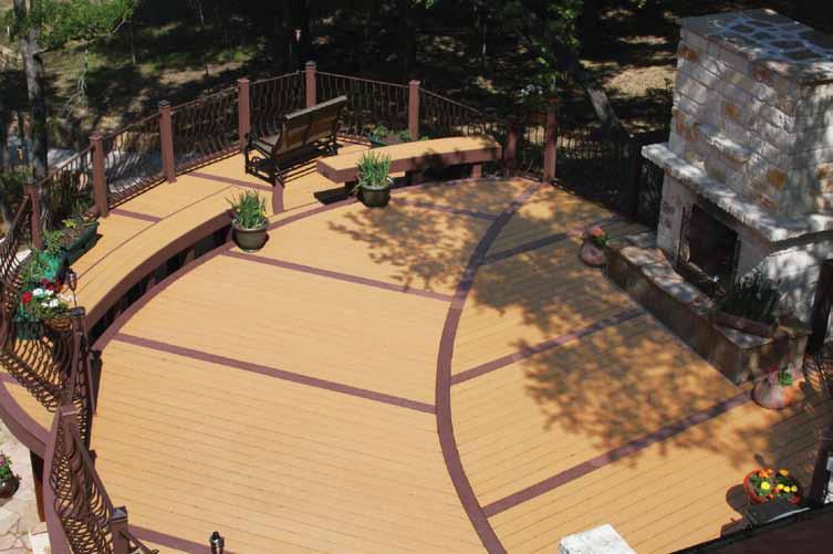
2 Installation Instructions As with any building project, use proper eye, ear, and lung protection equipment. Always follow local building and safety codes. Warranty LifeCycle Composite Decking is manufactured by Advanced Environmental Recycling Technologies, Inc. (A.E.R.T.) and is backed by a 25-year limited residential and a 20-year limited commercial warranty against rot, decay and insect damage. For complete warranty details, please visit our website at General Cleaning & Maintenance Instructions In an outdoor environment, periodic cleaning will help keep your deck looking new. As with any flooring surface, periodic cleaning is recommended. The following are suggested cleaners for occasional maintenance. Corte-Clean Concrobuim For specific cleaning issues, please visit our website at
 2\" 6\" Board 1.5 5.5 (3.81 x 13.97 cm) LENGTH: 12 and 16 feet (3.66 and 4.88 m) 1\" 5\" Essential 1.0 5.")
 LENGTH: 8, 12, 16 and 20 feet (2.40, 3.66, 4.88 and 6.10 m) Bull Nose / Edge Trim 0.75 2.")
 Railing Systems Our railing systems and accessories are designed to naturally complement your")
 Post Collar 5.5 5.5 (13.97 x 13.97 cm) Post Cap 5.5 5.5 (13.97 x 13.97 cm) Baluster 1.5 1.265 (3.")
 LENGTH: 6 feet (1.")
3 Decking Systems 2" 4" Board (3.81 x 8.89 cm) LENGTH: 12 and 16 feet (3.66 and 4.88 m) 2" 6" Board (3.81 x cm) LENGTH: 12 and 16 feet (3.66 and 4.88 m) 1" 5" Essential (2.54 x cm) LENGTH: 8, 12, 16 and 20 feet (2.40, 3.66, 4.88 and 6.10 m) 1" x 6" Vantage (2.54 x cm) LENGTH: 8, 12, 16 and 20 feet (2.40, 3.66, 4.88 and 6.10 m) Bull Nose / Edge Trim (1.90 x 5.08 cm) LENGTH: 12 feet (3.66 m) Trim Board (1.70 x cm) LENGTH: 12 feet (3.66 m) Railing Systems Our railing systems and accessories are designed to naturally complement your LifeCycle deck or porch. 4" 4" Post (10.83 x cm) LENGTH: 51 inches ( cm) Post Collar (13.97 x cm) Post Cap (13.97 x cm) Baluster (3.81 x 3.21 cm) LENGTH: 38 inches and 12 feet (95.52 cm and 3.66 m) Magnum Railing (7.42 x cm) LENGTH: 6 feet (1.82 m) To view our railing systems on completed decks, please visit the photo gallery at

4 Installation Tools Fasteners All you ll need is a hammer and screw gun, circular saw (carbide-tipped blade with fewer than 20 teeth is recommended), level, tape measure, rasp and blue chalk line. Manufacturer recommends blue chalk since other colored chalk may stain the deck. Each post requires two, 1/2-inch carriage bolts 8-inches (20.32 cm) minimum length with 1-1/4-inch flat washer on back with nut. For deck board fasteners, we recommend #7, 2-1/4-inch stainless steel trim head screws for the decking and railing. If you do not want the screw heads to show on the deck boards use the following technique: Using a #7, 2-1/4-inch stainless steel trim head screw, countersink the screw into the decking material approximately 1/4 of an inch (0.64 cm). Carbide-tipped blade with fewer Carbide-tipped than 20 teeth. blade with fewer than 20 teeth. Carbide-tipped blade with fewer than 20 teeth. Using your thumb, lightly push the displaced decking material over the hole left by the trim head screw. Carbide-tipped blade with fewer than 20 teeth. Tap with a hammer, this will cover the trim head screw with decking material. *Installation tips: Using a 2-inch driver bit allows you to better gauge screw depth. Tap hole with edge of hammer for best results. Hidden Fasteners Our products are compatible with most hidden fastener systems. Please consult the installation instructions provided by the hidden fastener manufacturer, or contact our Customer Service department at For your convenience, some common building code requirements are reprinted here: Residential minimum handrail height is generally 36-inches (91.44 cm). Multi-family minimum handrail height is sometimes 42-inches ( cm). Baluster maximum spacing is generally 4-inches (10.16 cm) clear distance between balusters**. Maximum gap between bottom rail and deck surface is generally 4-inches (10.16 cm).** Some codes require a 2-inch (5.08 cm) maximum gap for multi-family applications. *For additional cleaning tips visit w w w.lifecycledecking.com. ** Spacing note: The precise language is generally do not allow passage of a sphere 4-inch (10.16 cm) in diameter. Be sure to check on the tolerance requirements of your local building code.
5 Post & Decking Installation 1. Layout and install joists at either 16-inch (40.64 cm) on-center (OC) when decking will be installed perpendicular to the joists, or 12-inch (30.48 cm) OC when deck boards will be installed diagonally or at an angle to the joists*. Joists must be level. 16" (40.64 cm) OC 12"(30.48 cm) OC 2. Attach posts to decking frame. DO NOT NOTCH POSTS. The maximum distance from center of post to center of post is 72-inches. ( cm) Square and level posts. A. Block posts and attach to rim joists with two bolts (1/2-inch carriage bolts 8-inch (20.32 cm) - minimum length with 1-1/4-inch flat washer and nut on back). Corner Post Blocking Interior View Corner Post Blocking Exterior View Bolt positions: The top bolt to be no more than 3-inches (7.62 cm) below the finished deck surface and the bolt spacing to be no less than 4-inches (10.16 cm) on-center. *For more information regarding technical specifications, please visit
6 3. Install LifeCycle decking using 2-1/4-inch, #7 stainless steel trim head screws, two screws per board per joist recommended. Screws should be a minimum of 1/2-inch (1.27 cm) from the board end. 1/8" (0.32 cm) Gap 1/4" (0.64 cm) Gap A. Allow 1/4-inch (0.64 cm) side-to-side spacing between deck boards. Allow 1/8-inch (0.32 cm) or greater end-to-end spacing between ends of boards butt joints. If installing in freezing weather, leave 1/4-inch (0.64 cm) butt joints. B. Cut deck boards to fit around post. Leave 1/8-inch (0.32 cm) gap between board and post. *Installation tips: Double joist at butt joint to ensure plenty of room for fasteners. Pre-drill using a 7/64-inch (0.25 cm) bit when too close to the edge to prevent splitting. Drive screw at a slight angle into joist. C. Staggering the butt joints on long decks usually improves the overall appearance of the finished deck. Some people also prefer a distinctive pattern for the deck boards. To achieve an interesting design, install a pattern board, which eliminates butt joints. D. Once the boards are in place, adjust the blade depth of your saw to match the thickness of your deck boards. Use a blue chalk line to mark your cut and go. To avoid staining the deck boards, use blue carpenter s chalk. Rasp the edges to finish. 4. Slip post collar over post onto deck if installing. *Installation tips: Router or rasp end of deck board using 1/4-inch round for a finished look. Allow 3/16-inch (0.47 cm) overhang for any rim joist imperfections (straight). If you choose not to use the trim board, maximum recommended overhang is 1-1/2-inches (3.81 cm).
7 Railing Installation Railing Orientation - Magnum Railing: To use the magnum railing, the top magnum rail must be installed with the long leg (4-inch, cm) in the horizontal orientation. The balusters sit on the ledge of the bottom leg of the bottom magnum rail and are covered by the top magnum rail leg. The top and bottom magnum rails allow the balusters to face either toward or away from the deck depending on which way the consumer prefers the rail system to be installed. For ease of installation, your railing kit comes with the following pieces: 2 6-foot (1.82 m) magnum railings (one top and one bottom rail) 14 balusters 1 post 5. Cut two temporary blocks from scrap material to the height you want the toe sweep, no less than 2-inches (5.08 cm) nor greater than 4-inches (10.16 cm). Place on inside of posts sitting on decking. A. Set bottom magnum rail on blocks (with the 4-inch (10.16 cm) leg resting on the blocks) and center on post. B. Place baluster against post and sit it on the bottom magnum rail (1-1/4-inch (3.18 cm) side against the post). 4" (10.16 cm) Baluster 3" (7.62 cm) 1-1/4" (3.18 cm) Temporary Blocks 2" (5.08 cm) x 4" (10.16 cm) *Installation tip: Use clamps to secure for easier installation. C. Using 2-1/4-inch, #7 stainless steel trim head screws, secure baluster to post, two screws at each end, and four additional screws evenly spaced between the end connections. D. Place second baluster against opposite post and repeat step C.
8 6. 7. Secure bottom magnum rail to each post baluster using two, 2-1/4-inch, #7 stainless steel trim head screws, repeat on other end of bottom magnum rail. Place top magnum rail on balusters (see railing orientation for details) and repeat fastening as in step 6. In addition, angle (toe nail) two, 2-1/4-inch, #7 stainless steel trim head screws from top magnum rail directly into each post. 8. Place a support block every two feet between bottom rail and decking for support. Secure support block with one, 2-1/4- inch, #7 stainless steel trim head screw through the bottom rail into the support block.
9 9. Use the formula below to determine the amount of balusters you need and the spacing between them. Measure the distance in inches between the inside of one post baluster to the inside of the other post baluster. This is your total space. 10. Attach baluster to top and bottom magnum rails using one, 2-1/4-inch, #7 stainless steel trim head screws. 4-inch (10.16 cm) maximum distance between balusters, visible opening check local building code. A. Divide the total space by 5, and round it off to a whole number. This is the number of additional balusters you need. B. Multiply the value in (A) by 1.5 and subtract it from your total space. *Installation tip: 3-1/2-inches (8.89 cm) between balusters is always a good starting point. C. Divide the value in (B) by the value of (A+1). This is the spacing between the balusters. You may want to cut two spacer blocks from scrap material or a baluster, the same width as answer C, and use these two spacers at top and bottom to place each baluster Attach post caps to top of post. *Installation tip: Quality outdoor adhesive can be used for caps. Additionally, for a finished look, install trim boards over the rim joists. Position flush with the top of the decking. A. Attach using 2-1/4-inch, #7 stainless steel trim head screws. One screw through the end or side of the decking, and three screws into the rim joist vertically every inches ( cm). B. We recommend putting the screw through the thickest part of the deck board (center between the top of the board and the bottom of a rib) when attaching the trim board, then the other three into the rim joist.
10 45-Degree Railing 13. Attach posts to decking frame. Square to straight side of rim joist and level. Follow procedures 2-4 to install posts and decking. 14. Determine the angle of the top magnum rail. A. Lay a top magnum rail centered on top of the two posts and mark angle (see railing orientation) and cut. B. Mark and cut the bottom magnum rail the same way, making sure to lay the 4-inch (10.16 cm) leg on the posts. 15. A. Place bottom magnum rail on blocks that are cut to the toe sweep height desired, no less than 2-inches (5.08 cm) nor greater than 4-inches (10.16 cm) 4-inch (10.16 cm) leg lying on blocks. B. Place baluster with 45-degree cut side against the post positioned at the 45-degree corner and sit on the bottom magnum rail. Attach it to the post using procedure #5C. C. Place a regular baluster against the diagonal baluster, sitting on bottom magnum rail and attach with three, 2-1/4-inch, #7 stainless steel trim head screws, evenly spaced top to bottom. 16. Finish with steps #5D through #11 with the exception of the post baluster that has been installed already in this 45-degree section (step #14).
11 Stair Railing 17. Attach posts to stair stringers (stringers should be 2-feet x 10-inch (0.60 m x cm) and placed 12-inch (30.48 cm) OC or less). Square posts to stringers and level. Be sure posts measure no more than 72-inches ( cm) from outside to outside at the angle of the stairway when using as a stair rail. Guard rail sections are sold in 72-inch ( cm) lengths and must be trimmed to fit between the posts. Allow for decrease in length from angle cuts. A. Follow step #2 to install posts to stair stringers (use corner post blocking method). 72" Maximum ( cm) 18. Install deck boards. Boards may be flush with riser or extend past the riser by 1-inch (2.5 cm). Use two, 2-1/4-inch, #7 stainless steel trim head screws per board per stringer. A. Optional: Cut and install kick boards (deck boards) along each stair rise. B. Install post collars if desired. C. Cut and install trim board on stringers if desired. Use procedures in step #12.
12 19. Lay a top and bottom magnum rail along the edges of the steps and up next to the post. A. Position both rails for marking with the 2-5/8-inch (6.66 cm) leg lying on the steps. B. Mark the rails on the inside faces of the two upright posts. 72" ( cm) C. Cut each rail along this mark (line). 20. Position bottom magnum rail 1/2-inch (1.27 cm) above edges of steps (check local code) support on blocks cut from scrap material. 21. Cut ends of two balusters at the same angle as the top and bottom magnum rails and use them as the post balusters. 22. To complete stair railing follow steps #5B through #11.
13 Understructure System Installation Solid Surface Installation Techniques (Concrete slab or rooftop) Due to varying soil conditions, building requirements, weather conditions, and end uses it is impractical to issue blanket construction requirements for the substructure. For rooftop applications, consult a roofing specialist for a suitable underlayment material. Exercise extreme care so that fasteners don t penetrate roof surface. It is the installer s responsibility to ensure that roof construction is safely supported to the installed terrace system. It is the installer s responsibility to ensure that all applicable building codes are met. It is the installer s responsibility to ensure that sufficient anchorage is used to resist any uplift requirements. Understructure fixed directly to supporting surface Understructure supported by protective underlayment Understructure supported by blocks with protective underlayment Garden Installation Techniques Due to varying soil conditions, building requirements, weather conditions, and end uses, it is impractical to issue blanket construction requirements for the substructure. It is the installer s responsibility to ensure that all applicable building codes are met. It is the installer s responsibility to ensure that sufficient anchorage is used to resist any uplift requirements. It is the installer s responsibility to ensure that a stable substructure is constructed. Installation on piers or curbstones Understructure unsupported span length* Installation on concrete blocks Installation in concrete *For more information regarding technical specifications, please visit
14 General Installation FIGURE 1 1. Allow a 0.6 cm (min.) gap between understructure and the stable structure. 2. Align understructure parallel to the direction of drainage. Space understructure in accordance with span chart.* 3A. Space understructure butt joints 0.6 cm. 3B. Inside of understructure to inside of understructure (from span chart)*. (3A) Butt Joint Figure 1 (1) (2) FIGURE 2 (3B) 4. Anchor understructure to concrete with 0.6 cm (min.) SS, HDG, or equivalent corrosion resistant anchors. Minimum penetration depth in to slab is 4.5 cm. 5. Place anchors 2.5 cm from each end. Understructure Figure 2 (5) (4) (4) 1 meter (max. spacing between anchors) on perimeter. NOTE: Install anchors according to manufacturer s instructions. Countersink heads below surface of the understructure. Check Local Building Codes to Make Sure Specified Anchors Meet or Exceed All Requirements.
15 Composite Deck Screw Installation FIGURE 1A 1A. 0.4 cm (or equivalent to #7) SS composite trim head deck screw. Minimum length for screws is the understructure thickness + deck board thickness - 6mm. Install two per deck board at every understructure location. 2A. Place screws approximately 2.5 cm from edge of board. 3A cm space. FIGURE 1B Top View: 1B. At deck board butt joints, fasten each end with two deck screws. Locate screws approximately 2.5 cm from end of board. 2B cm (min.) spacing at deck board butt joints. (1A) (2A) Anchor (3A) Composite Understructure Figure 1A Concrete Patio Slab (2B) (1B) Figure 1B *For more information regarding technical specifications, please visit
16 Hidden Deck Fastener Installation FIGURE 1A 1A cm spacing. FIGURE 1B Top View: 1B. Use two hidden fasteners per understructure location at deck board butt joints (as shown). 2B cm (min.) board spacing at butt joints. (1A) Hidden deck fastener Anchor Composite Understructure Figure 1A Concrete Patio Slab (1B) For cases where the understructure width is insufficient to accommodate two fasteners, install a second member running parallel to allow enough room for two fasteners. Figure 1B (2B) NOTE: Install according to manufacturer s recommended instructions.
17 Typical Installation FIGURE 1 Boards shown installed perpendicular to the understructure. If boards are installed at 45 to the understructure, understructure spacing is reduced by approximately 10 cm. Please reference the span chart* for the proper spacing for your specific installation. 1. Install first course of boards on the side opposite the structure. 2. Size last row of boards to fit. Leave 6mm (min.) gap between the board and the stable structure. 3. For a finished look, rout board ends and cut edges with a 0.3 cm radius bit. (3) Figure 1 (1) (2) Installation Fascia FIGURE 2 (5) Figure 2 1. Miter fascia corners for a finished look. 2. Install fascia with 0.4 cm (or equivalent to #7) SS trim head composite deck screws. Minimum length is fascia thickness 2.5 cm. Fasten approximately 2.5 cm from each end, no more than.3 meters apart meter (max.) fastener spacing for fascia installation 4. Allow 0.6 cm (min.) between bottom of fascia and slab for drainage. 5. Allow a 0.6 cm gap between the end of fascia and the stable structure. (4) (2) (1) (3) *For more information regarding technical specifications, please visit
18
19 For more information visit w w w.lifecycledecking.com
20 Your Authorized Dealer: For more information on our products, visit These railing system components are to be installed with strict accordance with the procedures described in these LifeCycle Installation instructions. Testing these railing systems has shown that they meet the requirements of the major model building codes in the U.S. Colors shown are as close to actual as printing reproduction will allow. LifeCycle professional grade decking and railing systems and accessories are manufactured by Advanced Environmental Recycling Technologies (A.E.R.T.). Under U.S. patent # and covered under ESR It s always better when you work with nature. Remember to recycle. LifeCycle is a registered trademark of Advanced Environmental Recycling Technologies, Inc Advanced Environmental Recycling Technologies, Inc. June 2011.
installation care & maintenance instructions moistureshield.com limited lifetime warranty
 installation care & maintenance instructions 866.729.2378 moistureshield.com limited lifetime warranty It s comforting to know that you re about to build a deck that gives you every possible advantage.
COMPOSITE RAILING INSTALLATION
 COMPOSITE RAILING INSTALLATION Tools All you ll need is a hammer and screw gun, circular saw (carbidetipped blade with fewer than 20 teeth is recommended), level, tape measure, rasp and blue chalk line.
Customer Service: Installation, Care and Maintenance
 Customer Service: 800-951-5117 Installation, Care and Maintenance Installation Instructions Easy step-by-step instructions for decking, railing and stairs. As with any building project, use proper eye
CONTRACTOR CERTIFICATION COURSE
 CONTRACTOR CERTIFICATION COURSE 1 Learning Objectives After completing this course you will be able to: Explain appropriate methods for storing and installing ChoiceDek decking Discuss care and maintenance
Installation Guide (888)
") BamDeck Installation Guide (888) 788-2254 The Collection Decking Systems BAMDECK 4G 5-7/16 Wide Plank Dims: 192 L x 5-7/16 W x 13/16 H BAMDECK 4G WIDE 8-1/4 Wide Plank Dims: 96 L x 8-1/4 W x 13/16 H BAMDECK
BamDeck Installation Guide (888) 788-2254 The Collection Decking Systems BAMDECK 4G 5-7/16 Wide Plank Dims: 192 L x 5-7/16 W x 13/16 H BAMDECK 4G WIDE 8-1/4 Wide Plank Dims: 96 L x 8-1/4 W x 13/16 H BAMDECK
DECKING INSTALLATION GUIDE
 STAIR TREAD INSTALLATION GUIDE Step 7: Install the Remaining Treads Repeat steps 2 to 6 for the remaining stair treads. Step 8: Install the Fascia 1. Measure the riser height. 2. Rip the fascia to the
Build Outdoor Stairs. Stair Building Terms There are five basic design elements you'll need to consider when planning outdoor stairs:
 Build Outdoor Stairs Stair Building Terms There are five basic design elements you'll need to consider when planning outdoor stairs: The Total Run (Fig. 1) is the total horizontal distance covered by the
Installation Instructions for. Before You Begin TOOLS REQUIRED
 Composite Railing System STEP-BY-STEP Installation Instructions for Spectrum Composite Railing Virtually maintenance free 20-year warranty EverNew Spectrum Railing system is designed to work with a number
Installation Guide (888)
") BamDeck Installation Guide (888) 788-2254 The Collection Decking Systems BAMDECK 3G 5-7/16 Wide Plank Dims: 96 L x 5-7/16 W x 13/16 H BAMDECK 3G 16FT. 5-7/16 Wide Plank Dims: 192 L x 5-1/2 W x 13/16 H
BamDeck Installation Guide (888) 788-2254 The Collection Decking Systems BAMDECK 3G 5-7/16 Wide Plank Dims: 96 L x 5-7/16 W x 13/16 H BAMDECK 3G 16FT. 5-7/16 Wide Plank Dims: 192 L x 5-1/2 W x 13/16 H
INSTALLATION INSTRUCTIONS MILLENNIUM DECKING Before Installing Millennium Decking, please read these instructions in their entirety.
 INSTALLATION INSTRUCTIONS MILLENNIUM DECKING Before Installing Millennium Decking, please read these instructions in their entirety. Safety PRE-INSTALLATION Compliance with all applicable local, state
Installation Instructions for. Handrail Component System
 Handrail STEP-BY-STEP Installation Instructions for Handrail Component System Rise in Inches Run in Inches 8 8.5 9 9.5 10 10.5 11 11.5 12 12.5 13 13.5 14 14.5 15 8.5 47 45 43 42 40 39 38 36 35 34 33 32
Vinyl Gazebo Instructions
 P a g e 1 Vinyl Gazebo Instructions 10 Vinyl Gazebo Shown Thank you for the purchase of your New Gazebo. Depending on the size of your Gazebo, installation can usually be completed in 1 to 2 days. These
CXT PRO RAILING INSTALLATION INSTRUCTIONS For Installations Using Aluminum and Glass Balusters Sold Separately
 CXT PRO RAILING INSTALLATION INSTRUCTIONS For Installations Using Aluminum and Glass Balusters Sold Separately CCRR-0171 PFS AA-652 Drill/power screwdriver Assorted drill bits Hammer Miter or circular
2x Bottom Bracket. 1x Rail Support STEP 1 STEP 2
 Level Railing Top Rail Bottom Rail Aluminum Baluster 2x Bottom Bracket 1x Rail Support Kit Includes: 1 - Top Rail (with Baluster Connectors installed) 1 - Bottom Rail (with Baluster Connectors installed)
Installation Guide. 203 Chesterra Drive, Dahlonega, GA Toll-Free ~ Fax ~
 Congratulations and Thank You for your purchase! DryJoistEZ is an easy to install structural aluminum joist that also provides an under-deck drainage system that you install over your deck framing system
The following instructions will guide you through the installation of your new vinyl railing.
 Installation Guide St. James Vinyl T-Rail Tools Required Protective eye glasses 3/8 x 3 Concrete Anchors/Fasteners (for Tape measure concrete installations) Variable speed drill/screwdriver Philips Driver
TREX TRANSCEND RAILING
 RAILING NOTES:» RAILINGS ARE DESIGNED TO BE INSTALLED OVER THE DECKING FRAME OR ON INSIDE OF RIM JOIST. NOTCHING OF PRESSURE-TREATED POSTS OR POSTS INSTALLED ON OUTSIDE OF RIM JOIST IS NOT ALLOWED.» All
ATLANTIS RAIL Contact Information
 ATLANTIS RAIL Contact Information Customer Service (800) 541-6829 (508) 732-9191 Spectrum System Installation Instructions Atlantis Rail s Spectrum System is an easy to install, universal cable railing
PAINT & MISC. Notes. Table of Contents. Front Handrail Posts Front Handrails Closet Shelving Exterior Deck...
 118 PAINT & MISC. Table of Contents Front Handrail Posts... 119 Front Handrails... 122 Closet Shelving... 125 Exterior Deck... 127 Look for painter s tape on the hammer drill for where to set the depth.
Level Railing. Installation Guide. v2.5 W W W. S O L U T I O N S A L U M I N U M. C O M
 Level Railing Installation Guide Top Rail Bottom Rail Aluminum Baluster 2x Bottom Bracket 1x Rail Support #909915 Kit Includes: 1 - Top Rail (with Baluster Connectors installed) 1 - Bottom Rail (with Baluster
INSTALLATION INSTRUCTIONS. Level Rail With Cap: Page 2 Level Rail Without Cap: Page 8 Stair Rail: Page 12
 INSTALLATION INSTRUCTIONS Level Rail With Cap: Page 2 Level Rail Without Cap: Page 8 Stair Rail: Page 12 LEVEL RAIL WITH CAP The testing was performed in accordance with procedures and methods referenced
RAILING R A IL ING 51
 RAILING RAILING 5 TREX TRANSCEND RAILING NOTES:» TREX TRANSCEND RAILINGS ARE DESIGNED TO BE INSTALLED OVER THE DECKING FRAME OR ON INSIDE OF RIM JOIST. NOTCHING OF PRESSURE-TREATED POSTS OR POSTS INSTALLED
12ft Octagon Bayside Gazebo Assembly Manual
 We recommend reviewing this Assembly Manual thoroughly before starting this project. Become familiar with the tools required and where and when assistants are necessary. If you re planning on finishing
Chapter 1. Beam and Sill Plates
 Chapter 1. Beam and Sill Plates 1.1 ESTABLISHING SQUARE SILL PLATE CHALK LINES 1.2 INSTALLING TREATED SILL PLATES 1.3 INSTALLING LAMINATE BEAM Tools needed by volunteers: Hammer Nail apron Tape measure
Deck Evaluation Checklist
 Date: Reported By: Project Name/Client: Year Deck was Built: I. Stairs A. Not Applicable B. Are there any visible signs of cracks, decay or over-notching? No Yes 1. If yes, where? C. Stairway width: (Hint:
10ft Octagon Bayside Gazebo Assembly Manual
 We recommend reviewing this Assembly Manual thoroughly before starting this project. Become familiar with the tools required and where and when assistants are necessary. If you re planning on finishing
Installation Guide. deckorum Composite Decking
 Installation Guide deckorum Composite Decking 1. Introduction Welcome to Deckorum installation Guide Please fully read the installation guide before commencing any installation works. This will provide
SECTION R507 DECKS DECKING LEDGER BOARD BEAM. FOOTING BEAM SPAN CANTILEVER For SI: 1 inch = 25.4 mm FIGURE R507.2 DECK CONSTRUCTION
 SECTION R507 DECKS R507.1 Application. The provisions of this section shall provide prescriptive requirements for the design and construction of all uncovered, wood-framed, single-span exterior decks.
4. Components and Stairs
 4. Components and Stairs 4.1 BUILDING WINDOW AND DOOR COMPONENTS 4.2 BUILDING STAIRS Tools needed by volunteer: Hammer Nail apron Tape measure Square Utility knife Pencil Tools and equipment needed: Materials
Dura-Lock Roof System
 DLR-14 Dura-Lock Roof System Assembly and Installation Instructions Read the instructions before starting the job. They explain the steps required to produce a finished product that will meet factory specifications.
Chapter 17 - Porch Trim
 Chapter 17 - Porch Trim Contents Chapter 17 - Porch Trim... 17-1 Timing & Prerequisites... 17-2 Trim on Porch Beams (Volunteer)... 17-4 Smart Trim on the Bottom of the Beam... 17-4 Smart Trim on the Inside
Step 2 - Measure and install joist hangers every 16". See Figure "B" above. Fill every hole in each
 Adding a deck is one of the most useful projects a homeowner can do to improve their home. Each deck is different and presents it's own set of challenges, so contact us with unique questions if they are
APPLICATION FOR A BUILDING PERMIT
 APPLICATION FOR A BUILDING PERMIT City of San Jacinto 595 S. San Jacinto Ave San Jacinto CA 92583 95.487.7330 fax 95.654.9896 Must print legibly, submit (3) sets of building and plot plans. Fill out all
T r e x Art i s a n Se r i e s Railing
 T r e x Art i s a n Se r i e s Railing I n s t a l l a t i o n In s t ru c t i o n s Trex Railing Components A. Trex Top Rail B. Trex Bottom Rail C. Trex Railing Support Bracket D. TrexExpress Railing
Stair Parts Installation. Tricks
 Stair Parts Installation Tips & Tricks Introduction Your DIY staircase guide Welcome to the Stairpart home installation guide. Your stairway is both a functional and focal point in your home, so keeping
DuraLife Porch Collection Installation Instructions
 DuraLife Porch Collection Installation Instructions Updated: 1/11 www.gaf.com 1 Getting Started... ilation and Drainage Plan the design of the porch it is the beginning of a successful project. DuraLife
Installation Guide. Deckorum. Composite Decking
 Installation Guide Deckorum Composite Decking 1. Introduction Welcome to Deckorum Installation Guide Please fully read the installation guide before commencing any installation works. This will provide
The following instructions will guide you through the installation of your new vinyl railing stair kit.
 Installation Guide Vinyl Standard Stair Railing Tools Required Protective eye glasses Tape measure Variable speed drill/screwdriver Rotary hammer or hammer drill and masonry percussion bit recommended
A Step-by-Step How To Guide
 HOW TO REMODEL YOUR STAIR A Step-by-Step How To Guide Add new life to your staircase and achieve professional results. 1 Renovating your staircase is more than a remodel, it s a transformation of your
TREX ENHANCE RAILING (Also Applies to Trex Select Railing) Installation Instructions
 Installation Instructions") TREX ENHANCE RAILING (Also Applies to Trex Select Railing) NOTE: All Enhance Railing lengths are manufactured at CLEAR SPAN dimensions (spanning between space of posts): 7" for 6' clear span. Note that
TREX ENHANCE RAILING (Also Applies to Trex Select Railing) NOTE: All Enhance Railing lengths are manufactured at CLEAR SPAN dimensions (spanning between space of posts): 7" for 6' clear span. Note that
U. M. ARMY Texas Conference. Wheel Chair Ramp Manual
 U. M. ARMY Texas Conference Wheel Chair Ramp Manual June 2014 U. M. ARMY Texas Conference Building & Repair Tips Wheelchair Ramps Complete a site survey to determine the design and layout of the ramp.
TREX SELECT RAILING Installation Instructions
 RAILING NOTE : All Trex Select Railing lengths are manufactured at ON CENTER dimensions (spanning from center of each post): 67-5/8" (76.8 cm) for 6' (.83 m) on center, and 9-5/8" (35.3 cm) for 8' (.44
Call (770) STEP 6: Caulk bolt hole within the bracket for protection from the elements.
 STEP 6: Caulk bolt hole within the bracket for protection from the elements.") Call (770) 777 7007 Structural Deck Support System: Product Numbers: H1-GQ, H2-GCL (Also applies to H1-GK and H2-GCR) STEP 1: Following the spacing guidelines per the deck design and joist layout, mark
Call (770) 777 7007 Structural Deck Support System: Product Numbers: H1-GQ, H2-GCL (Also applies to H1-GK and H2-GCR) STEP 1: Following the spacing guidelines per the deck design and joist layout, mark
Installation Guide. Capped Cellular PVC Fencing. Table of Contents. Storage and Handling Tools Needed Fence Layout and Locating Posts
 Capped Cellular PVC Fencing Installation Guide Table of Contents Storage and Handling Tools Needed Fence Layout and Locating Posts Installation instructions 4 x 4 Over Sleeve Post - 3.5 Rail Privacy Shadowbox
Vertical Offset Base and Safety Rail System Installation Instructions
 Section 5 Vertical Offset Base and Safety Rail System Installation Instructions The vertical offset base and safety rail assembly are designed to be used in residential construction for sloped or flat
A ledger/header board is the next step if you are attaching your deck to an existing structure.
 CE 101, Spring 2006 Step-by-Step Deck Construction 1 / 7 Step 1 Mark off the deck area using string and "batterboards" (Fig. 2) making sure that it is level and square. The string will help you visualize
TREX SELECT RAILING. Installation Instructions PARTS
 RAILING NOTE : All Trex Select Railing lengths are manufactured at ON CENTER dimensions (spanning from center of each post): 67-5/8" (76.8 cm) for 6' (.83 m) on center, and 9-5/8" (35.3 cm) for 8' (.44
Build Like a Pro: Building a Deck
 This is an excerpt from the book Build Like a Pro: Building a Deck by Scott Shuttner Copyright 2002 by The Taunton Press www.taunton.com JOISTS PRO TIP Step up to a larger joist whenever you come close
12ft Octagon (Precut) Creekside Gazebo Assembly Manual
 Creekside Gazebo Assembly Manual") 12ft Octagon (Precut) Creekside Gazebo Assembly Manual Aug 1st, 2008 Revision #9 In Florida, additional hardware may be required that is not included in kit due to hurricane winds. Please check with local
12ft Octagon (Precut) Creekside Gazebo Assembly Manual Aug 1st, 2008 Revision #9 In Florida, additional hardware may be required that is not included in kit due to hurricane winds. Please check with local
Post & Rail. Includes: Crossbuck, 2-Rail, 3-Rail and 4-Rail POST SUPPORT OPTIONS
 Post & Rail Includes: Crossbuck, 2-Rail, 3-Rail and 4-Rail STAGGER RAIL ENDS FOR GREATER STRENGTH ALLOW 1-1/2" GAP ON HINGE SIDE OF GATE AND 1-1/4" ON LATCH SIDE OF GATE HARDWARE DIG HOLES 30" MINIMUM
Grand Garden Chalet 6X3 Assembly Manual - Costco
 Revision #16 March 22nd, 2013 Grand Garden Chalet 6X3 Assembly Manual - Costco Thank you for purchasing a Grand Garden Chalet. Please take the time to identify all the parts prior to assembly. Please use
UltraDeck. Decking & Railing Installation Guide.
 UltraDeck Decking & Railing Installation Guide www.midwestmanufacturing.com Table of Contents: General Guidelines for Deck Installation 4 Plank Board Installation 6 QuickCap Installation 8 Cladding & Endcap
ONE AND TWO FAMILY DWELLINGS Uncovered Decks July, 2007
 ONE AND TWO FAMILY DWELLINGS Uncovered Decks July, 2007 In the City of Lee s Summit, the construction of uncovered decks with a floor surface more than 30 inches above the adjacent grade level requires
Double Beam Freestanding Pergola Installation Guide
 Double Beam Freestanding Pergola Installation Guide Patent Pending. Copyright 2011 USAVinyl, LLC - All Rights Reserved The information contained in these instructions are proprietary to USAVinyl, LLC and
6X3 Patio Garden Shed Assembly Manual
 Thank you for purchasing a 6x3 Patio Garden Shed. Please take the time to identify all the parts prior to assembly. Revision #4 July 6th, 2016 6X3 Patio Garden Shed Assembly Manual Please use Safety Eyewear
Installation Guidelines
 Page 1 Tools You ll Need 4 ft. Carpenter s level Chalk line (to mark U channel locations) Cordless drill/nut driver Caulking gun Chop saw with a metal cutting blade on it (required to make accurate and
woodworkersjournal.com MATERIAL LIST
 MATERIAL LIST T x W x L 1 Legs (2) 1 1 2" x 3 1 2" x 36 7 16" 2 End Uprights (2) 1 1 2" x 3 1 2" x 32 1 2" 3 Stringers (4) 1 1 2" x 3 1 2" x 42" 4 Top Cladding, Long (2) 3/4" x 7 1 4" x 65 3 4" 5 Side
3. Use base plate as template (see FIG. 4-1) to mark location for fasteners.
 to mark location for fasteners.") Plan the layout of the railing it is the beginning of a successful project. Getting Started... 1. Completely read the application instructions before starting the installation of the railing. 2. Properly
Plan the layout of the railing it is the beginning of a successful project. Getting Started... 1. Completely read the application instructions before starting the installation of the railing. 2. Properly
TREX SIGNATURE (FORMERLY REVEAL) RAILING Installation Instructions
 RAILING Installation Instructions") TREX SIGNATURE (FORMERLY REVEAL) RAILING Installation Instructions NOTES:» SIGNATURE POSTS CANNOT BE USED WITH SIGNATURE TRADITIONAL OR SIGNATURE COCKTAIL DESIGNS, ONLY PRESSURE TREATED POSTS/ POST SLEEVES
TREX SIGNATURE (FORMERLY REVEAL) RAILING Installation Instructions NOTES:» SIGNATURE POSTS CANNOT BE USED WITH SIGNATURE TRADITIONAL OR SIGNATURE COCKTAIL DESIGNS, ONLY PRESSURE TREATED POSTS/ POST SLEEVES
INS TA L L AT I O N IN S T R U C T I O N S F O R BEF O R E YO U BE G I N TOOLS REQUIRED
 STEP-BY-STEP Composite Railing Systems INS TA L L AT I O N IN S T R U C T I O N S F O R SPECTRUM AND EVERNEW 20 COMPOSITE RAILING Virtuallymaintenancefree 20-yearwarranty EverNew Spectrum and EverNew 20
2x2 Baluster Railings FPO REDWOOD. Naturally beautiful Easy to use Practical and economical Durable and stable Resistant to decay and insects
 B U I L D I T W I T H REDWOOD 2x2 Baluster Railings FPO R E D W O O D Naturally beautiful Easy to use Practical and economical Durable and stable Resistant to decay and insects 2x2 Baluster Railings RAILING
DECKS. Stairway illumination Positive attachment of ledger Lateral load connection required board (R507.2) required (R ) (R311.7.
 required (R ) (R311.7.") DECKS Max. riser height-7 ¾ Min. tread depth-10 Landings required at (R311.7.5.1) (R311.7.5.2) top and bottom of stairs (R311.7.6) Notched guardrail post NOT allowed Graspable handrail required Spacing
DECKS Max. riser height-7 ¾ Min. tread depth-10 Landings required at (R311.7.5.1) (R311.7.5.2) top and bottom of stairs (R311.7.6) Notched guardrail post NOT allowed Graspable handrail required Spacing
PRIVACY INSTALLATION FOR: Standard 6 H x 8 W Privacy Fence 4 x 4 Post Sleeve & Brackets Dog Ear or Straight-Edge Pickets 1.75 x 3.
 PRIVACY INSTALLATION FOR: Standard 6 H x 8 W Privacy Fence 4 x 4 Post Sleeve & Brackets Dog Ear or Straight-Edge Pickets 1.75 x 3.5 Rail Storage and Handling Fence Preparation and Layout Locate and Set
Grand Garden Chalet 6X3 Assembly Manual
 Revision #11 June 15, 2010 Grand Garden Chalet 6X3 Assembly Manual Thank you for purchasing a Grand Garden Chalet. Please take the time to identify all the parts prior to assembly. Please use Safety Eyewear
Perennial Wood Decking Installation Guide
 Perennial Wood Decking Installation Guide 1 WARNING! Read this entire Installation Guide prior to installing your Perennial Wood decking. Leave this guide at the job site. Table of Contents Perennial Wood
Balustrade Systems / Installation Instructions
 A. PARTS AND SUPPLIES NEEDED FOR INSTALLATION Hardware included for each 10 section of rail: 2 3 x 1-1/2 L-brackets 4 1-3/4 x 3/16 Blue hex-head screws for anchoring the L-brackets to the newel cap, column
SIGMADEK BOARD TM SAFETY AND ASSEMBLY GUIDE
 SIGMADEK BOARD TM SAFETY AND ASSEMBLY GUIDE PLEASE, READ THE SAFETY AND ASSEMBLY GUIDE THOROUGHLY PRIOR TO ASSEMBLING YOUR SIGMADEK BOARD TM. WARNINGS 1. REFER TO ANY LOCAL BUILDING CODE FOR JURISDICTIONAL
Gambrel Barn with Overhang Manual
 Tools Needed: -Cordless Drill (12V or higher) -#2 Square Drive Bit -Hammer -6 Step Ladder -Tape Measure -Square utility knife w/ blade & hook blade -Speed Square Little Cottage Co. PO Box 455 Berlin, OH
Installation of Balustrade Systems
 Installation of Balustrade Systems IMPORTANT: Be sure to mark the center point of each newel post's location prior to installation to insure proper spacing. All product interfaces must use PL Premium Adhesive
INSTALLATION INSTRUCTIONS GUIDE
 CERTAINTEED RAILING AND DECKING INSTALLATION INSTRUCTIONS GUIDE Kingston Vinyl Railing and Vinyl Decking CONTENTS Important Information Before You Begin...3 Helpful Hints, Tips, Fire Information and Tools
With Illustrations, Drawings & Step By Step Details. Click Here To Download 12,000 Shed Plans. 1 P a g e Download 12,000 More Shed Plans
 With Illustrations, Drawings & Step By Step Details Click Here To Download 12,000 Shed Plans 1 P a g e Download 12,000 More Shed Plans Table of Contents OVERVIEW... 3 MATERIALS & CUTTING LISTS... 4 DRAWINGS,
NewTech - CleverDeck Composite Decking Installation Guidelines
 NewTech - CleverDeck Composite Decking Installation Guidelines Composite decking has unique characteristics and requires specific fixing requirements that differ from timber. We strongly recommend that
10X12 Arched Breeze Pergola Assembly Manual Outdoor Living Today
 10X12 Arched Breeze Pergola Assembly Manual Outdoor Living Today ITEM# BZ1012ARCH Revision 2 March 25th/2015 Note: Post Mounting Hardware is NOT included in this kit. Please confirm with your local building
Page 1 of 18. SunRail System Installation Instructions
 Page 1 of 18 SunRail System Installation Instructions Page 2 of 18 SunRail Stainless Steel Railing Installation Guide Table of Contents Before You Begin 3 Installing Surface Mount Bases for a Two Rail
Grand Garden Chalet 6X3 Assembly Manual
 Revision #8 November 1, 2009 Grand Garden Chalet 6X3 Assembly Manual Thank you for purchasing a Grand Garden Chalet. Please take the time to identify all the parts prior to assembly. Please use Safety
PATIO INSTALLATION MANUAL
 PATIO INSTALLATION MANUAL A few minutes spent reviewing the following instructions will help insure quick and proper assembly. The Patio Sauna Kit will arrive on a stretchwrapped pallet including pre-built
INSTALLATION INSTRUCTIONS
 New installation instructions effective May 1, 2001 TimberTech Deck/Railing INSTALLATION INSTRUCTIONS ANDWARRANTY General Information TOOLS For all TimberTech Engineered Decking Systems products, standard
Chapter 20. Exterior Finish Work
 Chapter 20. Exterior Finish Work 20.1 INSTALLING STORM DOORS 20.2 INSTALLING TOE KICK BOARD 20.3 INSTALLING PORCH RAILS 20.4 INSTALLING HOUSE NUMBERS 20.5 INSTALLING MAILBOX 20.6 AIR SEALING EXTERIOR PENETRATIONS
TREX REVEAL RAILING Installation Instructions
 TREX REVEAL RAILING NoteS:» Reveal railings are designed to be attached with posts installed at a clear span of 6' (.8 m) or 8' (.44 m).» If installing at exact span lengths of 6' (.8 m) or 8' (.44 m),
AFCO-Rail Post INSTALLATION INSTRUCTIONS AFCO-RAIL POST
 AFCO-Rail Post INSTALLATION INSTRUCTIONS TOOLS REQUIRED: Drill Bits (for the appropriate fastener) Drill (with adjustable clutch, recommended) Level String Line Tape Measure Tools to install fasteners
 JOIST DETAILS Plate nail, 16d (0.15" x 1 ") at 1 on-center Blocking panel: 1 1 8" TJ Rim Board, 1 1 TimberStrand SL or TJI joist Toe nail, 10d (0.11" x ") at on-center A1 CS BEAM DETAILS L1 eb stiffener
Horizontal Cable Systems
 ALUMINUM RAILING INSTALLATION INSTRUCTIONS v2012 orizontal Cable Systems 1) Check Contents Of Packages: Verify that all parts have arrived and that they match the packing list. 1A) Coastal applications:
COMPOSITE SIDING INSTALLATION GUIDE
 CENTURY HOME LIVING COMPOSITE SIDING INSTALLATION GUIDE Read all instructions prior to installing any siding product. Failure to install and finish this product in accordance with all local building codes,
CONTENTS TOOL LIST U P S I D E I N N O V A T I O N S, L L C RAMP AND STEP SYSTEM ASSEMBLY INSTRUCTIONS. Revised: June 2013
 U P S I D E I N N O V A T I O N S, L L C RAMP AND STEP SYSTEM ASSEMBLY INSTRUCTIONS TOOL LIST Required Tools: - Reciprocating Saw with Metal Cutting Blade - Drill - 7/16 Drill Bit for Metal Drilling -
Ohlson Project Property Owner: Kathy Ohlson Property Address: Deer Lake Rd. Derwood MD 20855
 Ohlson Project Property Owner: Kathy Ohlson Property Address: 16116 Deer Lake Rd. Derwood MD 20855 Trademark LLC Prepared By: Travis Murphy Drawing Index 1. Cover 2. Rear Elevation 3. Top View 4. Dimensions
10 x 10 Flat Top Two Tone Pergola
 0 x 0 Flat Top Two Tone Pergola Models: Bordeaux ASSEMBLY GUIDE OPTIONAL ACCESSORIES Arch Kit System ( Arches) Privacy Fence Panel System ( Panels & Middle Post) Bolt Down Bracket Kit ( for Pergola) Ver.0-00
MODERN PERGOLA INSTALLATION GUIDE. When only the best will do.
 MODERN PERGOLA INSTALLATION GUIDE When only the best will do. TOOLS LIST Drill(s) 3/8" Magnetic Driver (s) 12" Drill Extension #2 Square Drive bit for Drill or Driver Level Tape Measure Hammer Drill if
Fold-A-Way Patio Door ASSEMBLY & INSTALLATION GUIDE
 Fold-A-Way Patio Door ASSEMBLY & INSTALLATION GUIDE This instruction guide provides the minimum recommended procedures to correctly prepare the rough opening, install a fold-a-way patio door unit and apply
SHADOWBOX INSTALLATION FOR: Standard 6 H x 8 W Shadowbox Fence 5 x 5 Routed Posts Dog Ear or Straight-Edge Pickets 1.75 x 3.5 Rail
 SHADOWBOX INSTALLATION FOR: Standard 6 H x 8 W Shadowbox Fence 5 x 5 Routed Posts Dog Ear or Straight-Edge Pickets 1.75 x 3.5 Rail Storage and Handling Fence Preparation and Layout Locate and Set Posts
Qwik-Fence Installation Instructions
 Qwik-Fence Installation Instructions 1 Tools Required The following installation instructions should be used as a guide for installing Folding Guard Qwik-Fence Partitions. Good common sense and appropriate
Now available at participating Feeney (2/14) AF# A. Stores. 1/8'' Stainless Steel Cable Assemblies to Enhance Any Railing and Any View!
 AF# A. Stores. 1/8'' Stainless Steel Cable Assemblies to Enhance Any Railing and Any View!") 2014 Feeney (2/14) AF# 2009-236A Now available at participating Stores 1/8'' Stainless Steel Cable Assemblies to Enhance Any Railing and Any View! Easy-to-install, prefabricated cable assemblies are an
2014 Feeney (2/14) AF# 2009-236A Now available at participating Stores 1/8'' Stainless Steel Cable Assemblies to Enhance Any Railing and Any View! Easy-to-install, prefabricated cable assemblies are an
Chapter 16. Underlayment and Finish Stairs
 Chapter 16. Underlayment and Finish Stairs 16.1 INSTALLING UNDERLAYMENT & DRICORE 16.2 FINISHING STAIRS Tools needed by volunteers: Hammer Nail apron Tape measure Tools and equipment needed: Extension
Calistoga Spa Surround
 B U I L D I T W I T H REDWOOD Calistoga Spa Surround R E D W O O D Naturally beautiful Easy to use Practical and economical Durable and stable Resistant to decay and insects Calistoga Spa Surround BUILD
PVC Composite Railing & Stair Kit
 FREEDOM-WEB PVC Composite Railing & Stair Kit INSTALLATION INSTRUCTIONS Read all instructions prior to installing product. Refer to manufacturers safety instructions when operating any tools. To register
TOLL FREE:(888) FAX:(941) ASSEMBLY of ProTEC CONCRETE STRUCTURAL INSULATED PANEL
 FAX:(941) ASSEMBLY of ProTEC CONCRETE STRUCTURAL INSULATED PANEL") ASSEMBLY of ProTEC CONCRETE STRUCTURAL INSULATED PANEL The ProTEC panels are manufactured with grooves on all four sides to accept the steel components. This grooving applies to the regular panel whose
ASSEMBLY of ProTEC CONCRETE STRUCTURAL INSULATED PANEL The ProTEC panels are manufactured with grooves on all four sides to accept the steel components. This grooving applies to the regular panel whose
Typical Deck Details
 Based on the 2009 Michigan Statewide Building Code guard decking ledger board fasteners existing house floor construction guard post attachment ledger board attachement to existing house s footing beam
Chapter 7 - Porch Framing
 Chapter 7 - Porch Framing Contents Chapter 7 - Porch Framing... 7-1 Timing & Prerequisites... 7-2 Concrete Porches Caps (Contractor)... 7-3 Organize the Porch Framing Lumber... 7-3 Types of Porch Roofs...
COMPACT DECK. Compact Deck Project Plan #850 Sheet 1 of Riverside Dr., Suite 212 Metairie, LA SouthernPine.com SouthernPineDecks.
 COMPACT DECK Project Plan #850 Sheet 1 of 6 This plan contains an attractive deck design that two handy persons with intermediate building skills can construct in a weekend. Build it with versatile pressure-treated
Assembly Instructions 10 X 10 Aluminum Roof Support
 Assembly Instructions 10 X 10 Aluminum Roof Support Aluminum Roof Support Bolt Package 16-5/16 X 2 ¼ SS Bolt 24-5/16 X 1 SS Bolt 40-5/16 SS Nylon Lock Nuts 16-5/16 SS Flat Washers 28-4 ½ Wood Screws 36-1
8x12 SpaceMaker Garden Shed Assembly Manual
 8x12 SpaceMaker Garden Shed Assembly Manual Version #6 Revised June / 2007 Thank you for purchasing a 8x12 SpaceMaker Garden Shed. Please take the time to identify all the parts prior to assembly. Safety