innovations 2013 More than 100 innovations in the fields of: - Cassette buffer magazines - Zero-Point Clamping Systems - Hydraulic Clamping System
|
|
|
- Valerie West
- 5 years ago
- Views:
Transcription


1 innovations 2013 CLAMPING. SCREWING. LOCKING. More than 100 innovations in the fields of: - Cassette buffer magazines - Zero-Point Clamping Systems - Hydraulic Clamping System - Grippers - and much more... Catalogue 2013


2 Company history 1890 Company founded as a lock manufacturer by Andreas Maier Product range extended to include spanners Production line assembly of Fellbach locks. We generate excitement. Since its founding by Andreas Maier in 1890, our company has lived though many exciting times. Today we are the leading manufacturer in Europe, supplying over 5,000 different products from the fields of clamping, hand tools and locks. With this extensive product range we can meet all of our customers needs and requirements. But providing optimal quality means meeting the challenges at all levels: Expert consultation, modern team organisation, individual solutions (including special developments), flexibility in response to changing conditions, etc. And we ourselves find this so exciting that we look forward every day to shaping the market together with our employees and our customers both now and in the future. That is something you can count on AMF introduces clamping elements and diversifies into workpiece and tool clamping technology Toggle clamps extend the AMF product range. AMF catalogues are now printed in ten languages Further specialisation into hydraulic clamping technology Clamping and fixture systems round off AMF s clamping expertise AMF team organisation in all sectors of the business. Quality management with certification to ISO AMF Service Guarantee for all products Introduction of the ZPS zero-point clamping system the magnetic clamping technology extends the AMF product range Development and marketing of AMF Vacuum clamping technology 2012 AMF-Writer and AMF-Cleaner for automated labelling and cleaning via the tool spindle 5 individual development And if the product you need doesn t exist? Just ask us: We will find the best solution for you whether it is a special version or a completely new development. 4 Warranty We stand by our high quality standards. We handle customer complaints very liberally and without red tape whenever possible even after the end of the warranty period. 3 guaranteed quality standard AMF stands for manufacturing in-house with the utmost care. A tradition we have upheld since 1890 and naturally for many years now with a modern quality management system to ISO short delivery times AMF s finished goods inventory with over 5,000 items guarantees a delivery readiness of 98%. You can also count on each warehouse item you order being shipped to you on the same day. 1 service from genuine experts Different tasks, different solutions. In AMF s professional product range, you can find the right solution quickly and reliably: either from your local dealer or with help from the specialists in our teams. A phone call is all it takes. e Made in Germany It goes without saying that our range of products is developed and manufactured by our team of employees in Germany. Managing Directors > Johannes Maier Volker Göbel THE AMF SERVICE GUARANTEE > Assuredly on the way to the top 2 innovations 2013 ANDREAS MAIER FELLBACH
3 Contents For an overview in numerical / alphabetical order, see catalogue pages Cassette buffer magazine and gripper 6-9 Mechanical zero-point clamping system Modular height adapter Clamping module K02 and 4-way clamping STATION Clamping modules for automation and accessories Mechanical collet Pressure booster and pump unit Block cylinders Swing, vertical, centring and Low pressure link clamp Hydraulic clamping systems accessories AMF-WRITER SLIMLINE 95 ANDREAS MAIER FELLBACH INNOVATIONS

4 ANDREAS MAIER FELLBACH


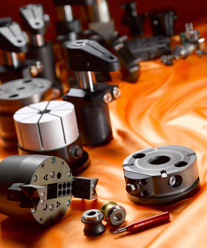
5 Low-cost automation for machine tools - cassette buffer magazine and gripper from AMF A perfect team. With the cassette buffer magazines and grippers from AMF, your machine tool will run by itself. Regardless of how many different workpieces, once it is set up, the tool works around the clock. Here we offer you an efficient alternative to expensive robots or automation cells. Existing shift models can be supplemented simply and flexibly by one or more worker-free shifts. This dramatically increases your machine run time and makes your entire production more economical. The advantages at a glance: > Economical and flexible automation solution > Production of different workpieces in one loading > Simple control by means of M-commands > Cassette buffer magazine serves as storage and/or transport unitt > Combined application of various gripper types Talk to us about it! INNOVATIONS

![529933 375 x 375 7 500 5 50-300 5 300 522375 500 x 500 7 500 5 50-300 5 350 [Kg] Cassette buffer magazines are used to supply and feed unmachined parts and workpieces into the machine tool.](/docs-images/93/112953272/images/6-1.jpg "These modular magazines are often positioned next to the machine. They can, however, be integrated directly into machine tools. They are especially suitable for flexibly interlinking machines.")

6 Cassette buffer magazine No. 1700KSS Cassette buffer magazine Workpiece storage system for supply and feed of workpieces. Cassette size No. of cassettes Load bearing capacity per cassette [N] Drive, pneumatic [bar] Buffer speed [mm/s] Control via M-commands max x x [Kg] Cassette buffer magazines are used to supply and feed unmachined parts and workpieces into the machine tool. These modular magazines are often positioned next to the machine. They can, however, be integrated directly into machine tools. They are especially suitable for flexibly interlinking machines. By virtue of their attributes, the cassette buffer magazines are designed specifically for self-service by CNC machines, which depend on workpiece interchange within the movement range of the spindle. These magazines are suitable for both gantry machine centres, for cross-table machines and for machines with tables that execute entire movements in the X-axis. These magazines are the ideal solution for shafts and cubic components, as well as for cast or moulded components. Pallets or fixtures can also be stored. The permitted dimension of the components depends on the cassette size, which is largely freely selectable. Features: The cassette buffer magazine can be adapted to most space situations, since it can undergo practically any change of direction. The magazine is populated with cassettes in such a way that one cassette pocket is free at all times. To introduce the components into the grip range of the machine tool, the cassette moves temporarily into the operating range of the spindle. The protected cassette guide runs so smoothly that the magazine needs to be screened only at the transition point to the machine tool. The result is an affordable solution which also allows access to the workpieces at all times. The speed of the movements is preselectable. The pneumatically-driven cassette buffer magazine is actuated by the machine control via 3 to 5 M commands. The components can be positioned on the cassette in a flat or a stacked arrangement. Masks or stack and stop elements are ideal for fastening. Advantage: - Very high component stocking density - Quick and simple component access - Simple actuation via M-commands - Highly-flexible in terms of shape and dimensions - Suitable as a magazine and/or transport unit Dimensions: Cassette loading height Height adjustability L1 L2 L3 L4 L5 L INNOVATIONS 2013 ANDREAS MAIER FELLBACH


7 Cassette buffer magazine ANDREAS MAIER FELLBACH INNOVATIONS
 The Weldon gripper is used for inserting tools from one magazine or similar into a")

8 Weldon gripper No. 1610WG Weldon gripper Gripper for parts handling, suitable for tool machines with internal coolant supply (ICS) The Weldon gripper is used for inserting tools from one magazine or similar into a clamping device in a machine tool. The gripper is unloaded from the tool magazine and loaded into the machine spindle for this purpose. Standard actuation is via compressed air. The actuation medium is routed through the machine spindle. The medium flow can be used to close or open the gripper. The return movements occur under spring force. Features: Tool fixture Stroke H Gripping force Positioning compensation: For the exact positioning of components, e.g. against stops, the handling tool is provided with resettable compensating elements. This solution, integrated into the tool, considerably eases the handling of unmachined parts or semi-finished products and relieves the machine spindle. [N] Max. workpiece weight [Kg] SK SK HSK HSK Overload protection: To protect against costly repairs, the tool has safety devices which prevent spindle damage and expensive tool repairs in case of collision. The tool itself is provided with overload protection, which also permits an adjustable limitation of the gripping force. Advantage: - Affordable automation solution - Suitable for the handling of diverse workpieces - High gripping force - Compensating function in X,Y, Z and C - Overload protection against tool and machine spindle damage The length of the tool holder (dimension L4) can vary depending on version and manufacturer. Grip inserts: Not supplied as standard and must be ordered separately. On request: - Weldon grippers are available as both external and internal grippers. - It is possible to integrate a gripper status check. - Other sizes and versions are available. - Version with cooling lubricant (CL) for opening ad closing. Dimensions: D1 D2 L1 L2 L3 L4 L5 L6 L , , , , INNOVATIONS 2013 ANDREAS MAIER FELLBACH


9 Gripper inserts for gripper No Gripper inserts for gripper - prism Delivered in pairs. Hardened steel with wear-resistant surface. First side with horizontal and vertical prism, second side ribbed. L1 L2 L3 L For quick and safe part handling in the tool machine using the AMF Weldon gripper. The parts are mounted to the gripper carrier and mechanically secured. The grip inserts are suitable for all AMF Weldon grippers. They can be adapted to the workpiece size concerned by displacement on the gripper carrier. Insertion depth No Gripper inserts for gripper - universal Delivered in pairs. Hardened steel with wear-resistant surface. First side with four contact surface with ribbed surface, second side with four contact surfaces from soft plastic. L1 L2 L3 L For quick and safe part handling in the tool machine using the AMF Weldon gripper. The parts are mounted to the gripper carrier and mechanically secured. The grip inserts are suitable for all AMF Weldon grippers. They can be adapted to the workpiece size concerned by displacement on the gripper carrier. Insertion depth No Gripper inserts for gripper - finger Delivered in pairs. Hardened steel with wear-resistant surface. Hardened pin with flat clamping surface on one side. L1 L ,5 70 For quick and safe part handling in the tool machine using the AMF Weldon gripper. The parts are mounted to the gripper carrier and mechanically secured. L3 The grip inserts are suitable for all AMF Weldon grippers. They can be adapted to the workpiece size concerned by displacement on the gripper carrier. Insertion depth ANDREAS MAIER FELLBACH INNOVATIONS


10 Clamping module, mechanical No. 6208M Clamping module, mechanical Mechanical opening and closing. Quenched and tempered steel, plasma-nitrated. Repeat accuracy 0.01 mm. Mechanical zero point clamping system for time-optimised clamping during cutting and non-cutting machining. Especially suitable for the modular design of clamping solutions via zero point clamping system. Size Pull-in/locking force up to Holding force The mechanical assembly clamping module has high retention, insertion and closing forces. The clamping module can be positioned on the machine table and fastened via mechanical clamping elements at the circumferential clamping edge. The positioning bore for marking sleeves and a through bore for fastening via M12 countersunk screw on the grid pallets are provided on the underside. The locating bore for the K20 clamping nipple is also already made in the module. Tightening torque [Nm] K Dimensions: Size dia. D dia. D1 0/+0,01 dia. D2 F7 dia. DN E1 G H ±0.01 H1 H2 H3 L R S1 SW K M , INNOVATIONS 2013 ANDREAS MAIER FELLBACH


11 Clamping module, mechanical, with indexing No. 6208IM Clamping module, mechanical, with indexing Mechanical opening and closing. Quenched and tempered steel, plasma-nitrated. Repeat accuracy 0.01 mm. Size Pull-in/locking force up to Holding force Tightening torque [Nm] K Mechanical zero point clamping system with indexing grooves offset by 90 for time-optimised clamping during cutting and non-cutting machining. Especially suitable for the modular design of clamping solutions via zero point clamping system. The mechanical assembly clamping module with indexing grooves offset by 90 has high retention, insertion and closing forces. The clamping module can be positioned on the machine table and fastened via mechanical clamping elements at the circumferential clamping edge. The positioning bore for marking sleeves and a through bore for fastening via M12 countersunk screw on the grid pallets are provided on the underside. The locating bore for the K20 clamping nipple is also already made in the module. Dimensions: Size dia. D dia. D1 0/+0,01 dia. D2 F7 dia. DN E1 G H ±0.01 H1 H2 H3 L R S1 SW K M , ,5 13 ANDREAS MAIER FELLBACH INNOVATIONS


12 4-point clamping station, mechanical No. 6207S4 4-point clamping station, mechanical Case-hardened steel, plasma-nitrided. Repetition accuracy mm. Mechanical opening and closing. For quick, simple and time-optimised positioning and clamping of workpieces or fixtures on the machine table. Actuating the clamping screw opens or closes all four clamping points at the same time. Extremely high retraction and retention forces are achieved thanks to the stable, high-quality design of this clamping station. Size Pull-in/locking force up to Holding force The 4-point clamping station is opened and closed using a WAF 13 hexagon wrench key. It can be fastened to the machine table either by the four M12 fastening bores or via mechanical clamping devices. A diverse range of suitable clamping devices for fastening can be found in our AMF Catalogue Mechanical clamping elements. Tightening torque [Nm] , Dimensions: A B dia. DN G G1 H ±0.01 H1 R R1 R2 SM SW M12 M INNOVATIONS 2013 ANDREAS MAIER FELLBACH


13 Interchangeable pallet and clamping nipple No. 6207P4-52 Interchangeable pallet Steel, burnished. Complete with 4 clamping nipples. Repeat accuracy mm. Size A B dia. DN G H H1 SM M Workpieces or fixtures are mounted on the interchangeable plate and then positioned and clamped on the mechanical 4-point clamping station with order The interchangeable plate is populated during machining, thus permitting longer machine operation. On request, we can incorporate mounting holes according to your specifications in the change pallet. The 4 clamping nipples are supplied as standard. No. 6207ZN-15 Clamping nipple Tempered steel, burnished. Size dia. D dia. DN G H H1 H2 SW M Clamping nipples suitable for mechanical 4-point clamping station with order clamping nipples are required for clamping on the 4-point clamping station. These nipples can, for example, be screwed into fixtures or into the workpieces themselves. ANDREAS MAIER FELLBACH INNOVATIONS


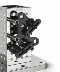
14 SIMPLY CLEVER COMBINATIONS - Modular height adapter for your flexible production With the new modular height adapters from AMF, your production becomes even more flexible and economical. Cleverly combined, you now have an efficient opportunity to adapt your production process more simply, flexibly and quickly to constantly changing requirements. Assembly element Intermediate elements Foot elements Base elements ANDREAS MAIER FELLBACH


15 The modular height adapters consist of three levels. The foot elements form the interface to the existing machine table. Building on this and with the use of intermediate elements, every clamping height can be achieved and, by combining different sizes, adapted flexibly to the contour of the workpiece. Assembly elements with integrated zero point clamping modules of the AMF Zero Point system complete the adapters. Through this, the workpiece is clamped in a process-reliable way. THE ADVANTAGES: > Simple direct clamping of the workpiece > Convenient 5-sided processing > Flexibly adaptable to every workpiece size and thickness > Freely selectable standard dimension innovations


16 Intermediate element No. 6210Z Intermediate element Quenched and tempered steel, plasma-nitrated. Size H ± K K K K K K K K K K K K K K The intermediate elements are used as height adapters for workpieces and clamping fixtures, and are mounted to the main elements. Workpieces are clamped by means of assembly elements. This clamping system can be used to move workpieces to the required machining height in the machine for 5-sided machining, or for the safe and quick clamping of workpieces with ledges and different clamping heights on the machine table. Advantage: Simple, quick and flexible clamping of complex workpiece contours on the machine table. Especially suitable for levelling workpieces or clamping fixtures at the necessary machine heights in the machine tool and for the reliable clamping of same. With the exception of overall heights H20 and 30, the locating bore for the clamping nipple, corresponding to size K10 and K20 is already made for the modification to zero point clamping modules. If two or more intermediate elements are used, they can be axially aligned and then bolted using centering sleeves. The 2 screws are supplied as standard. numbers for the centering sleeves: - Size K10: Size K20: Dimensions: Size dia. D dia. D1 H7 dia. D2 Screw DIN84 or ISO4762 E1 E2 G K F6 R S K M8x30 5,0 13,0 M K M8x30 5,0 13,0 M K M8x30 5,0 13,0 M8-50 3, K M8x50 5,0 13,0 M8-50 3, K M8x50 5,0 13,0 M8-50 3, K M8x50 5,0 13,0 M8-50 3, K M8x50 5,0 13,0 M8-50 3, K M12x25 9,5 9,25 M K M12x25 11,5 11,25 M K M12x25 11,5 11,25 M , K M12x55 11,5 11,25 M , K M12x55 11,5 11,25 M , K M12x55 11,5 11,25 M , K M12x55 11,5 11,25 M ,5 16 INNOVATIONS 2013 ANDREAS MAIER FELLBACH


17 Intermediate element No. 6210IZ Intermediate element, with indexing Quenched and tempered steel, plasma-nitrated. Size H ± K K K K K K K K K K K K K K The intermediate elements with indexing are used as height adapters for workpieces and clamping fixtures, and are mounted to the main elements. Workpieces are clamped by means of assembly elements. This clamping system can be used to move workpieces to the required machining height in the machine for 5-sided machining, or for the safe and quick clamping of workpieces with ledges and different clamping heights on the machine table. Thanks to the 4-point 90 indexing option, workpieces under strong machining forces can be secured to prevent radial distortion. Advantage: Simple, quick and flexible clamping of complex workpiece contours on the machine table. Especially suitable for levelling workpieces or clamping fixtures at the necessary machine heights in the machine tool and for the reliable clamping of same. With the exception of overall heights H20 and 30, the locating bore for the clamping nipple, corresponding to size K10 and K20 is already made for the modification to zero point clamping modules. If two or more intermediate elements are used, they can be axially aligned and then bolted using centering sleeves. The 2 screws are supplied as standard. numbers for the centering sleeves: - Size K10: Size K20: Slot nuts: Dimensions: Size dia. D dia. D1 H7 dia. D2 Screw DIN84 or ISO4762 E1 E2 G K F6 R S K M8x30 5,0 13,00 M K M8x30 5,0 13,00 M K M8x30 5,0 13,00 M , K M8x50 5,0 13,00 M , K M8x50 5,0 13,00 M , K M8x50 5,0 13,00 M , K M8x50 5,0 13,00 M , K M12x25 9,5 9,25 M K M12x25 11,5 11,25 M K M12x25 11,5 11,25 M , K M12x55 11,5 11,25 M , K M12x55 11,5 11,25 M , K M12x55 11,5 11,25 M , K M12x55 11,5 11,25 M ,5 ANDREAS MAIER FELLBACH INNOVATIONS


18 Base element No. 6210IFR Base element, with indexing for grid plates Size H ± M M The main element with indexing is positioned on grid plates M12 and M16 via a centering sleeve and then bolted. Intermediate elements or assembly elements can be adapted. This clamping system can be used to move workpieces to the required machining height in the machine for 5-sided machining, or for the safe and quick clamping of workpieces with ledges and different clamping heights on the machine table. Advantage: Simple, quick and flexible clamping of complex workpiece contours on the machine table. Especially suitable for levelling workpieces or clamping fixtures at the necessary machine heights in the machine tool and for the reliable clamping of same. numbers for the centering sleeves: - Ø15: Ø16: Ø22: Dimensions: Size dia. D dia. D1 H7 dia. D2 dia. D3 E1 E2 E3 G G1 G2 K F6 R R1 S M M12 M8 M M M12 M8 M INNOVATIONS 2013 ANDREAS MAIER FELLBACH


19 Base element No. 6210FN Base element for T-grooved plate Size H ± M The main element can be freely positioned and fastened on the grooved machine table at the circumferential clamping edge. Intermediate elements or assembly elements can be adapted. This clamping system can be used to move workpieces to the required machining height in the machine for 5-sided machining, or for the safe and quick clamping of workpieces with ledges and different clamping heights on the machine table. Advantage: Simple, quick and flexible clamping of complex workpiece contours on the machine table. Especially suitable for levelling workpieces or clamping fixtures at the necessary machine heights in the machine tool and for the reliable clamping of same. numbers for the centering sleeves: - Ø15: Ø16: Ø22: Clamping screw: Dimensions: Size dia. D dia. D1 H7 dia. D2 dia. D3 E1 E2 G G1 G2 dia. LK R R1 R2 R3 ±0,1 S M M12 M8 M ANDREAS MAIER FELLBACH INNOVATIONS
20 Spring washer for groove adapter No. 6210FN-M12-01 Spring washer for groove adapter Size M12 62 The spring washer is used to securely fasten the base element for T-grooved plates with M12 cheese head screws onto the machine table. Suitable for base element for T-grooved plate Dimensions: Size B G L L M12 10 M INNOVATIONS 2013 ANDREAS MAIER FELLBACH


21 Modular height adapter ANDREAS MAIER FELLBACH INNOVATIONS


22 Adapter reduction No. 6210A Adapter reduction from K20 to K10 Size H ± K20 - K The adapter element is used to reduce the intermediate element size K20 and K10.3 to size K10. Intermediate elements or assembly elements can be adapted. This clamping system can be used to move workpieces to the required machining height in the machine for 5-sided machining, or for the safe and quick clamping of workpieces with ledges and different clamping heights on the machine table. Advantage: Simple, quick and flexible clamping of complex workpiece contours on the machine table. Especially suitable for levelling workpieces or clamping fixtures at the necessary machine heights in the machine tool and for the reliable clamping of same. numbers for the centering sleeves: - Ø15: Ø16: Ø22: The fastening screws are supplied as standard. Dimensions: Size dia. D dia. D1 H7 dia. D2 dia. D3 dia. D4 Screw DIN84 or ISO4762 E1 E2 G G1 R R K20 - K M12x50 11,5 13 M12 M module module 22 INNOVATIONS 2013 ANDREAS MAIER FELLBACH

23 Adapter reduction No. 6210IA Adapter reduction from K20 to K10, with indexing Size H ± K20 - K The adapter element with indexing is used to reduce the intermediate element size K20 and K10.3 to size K10. Intermediate elements or assembly elements can be adapted. This clamping system can be used to move workpieces to the required machining height in the machine for 5-sided machining, or for the safe and quick clamping of workpieces with ledges and different clamping heights on the machine table. Thanks to the 4-point 90 indexing option, workpieces under strong machining forces can be secured to prevent radial distortion. Advantage: Simple, quick and flexible clamping of complex workpiece contours on the machine table. Especially suitable for levelling workpieces or clamping fixtures at the necessary machine heights in the machine tool and for the reliable clamping of same. numbers for the centering sleeves: - Ø15: Ø16: Ø22: Slot nuts: Dimensions: Size dia. D dia. D1 H7 dia. D2 dia. D3 dia. D4 Screw DIN84 or ISO4762 E1 E2 G G1 K F6 R R1 S K20 - K M12x M12 M ,5 ANDREAS MAIER FELLBACH INNOVATIONS


24 Adapter clamping module No. 6210H Adapter clamping module K5, hydr. to K10 Size Pull-in/locking force up to Holding force K The adapter element is used to reduce the intermediate element size K10 to the hydraulic clamping module K5. Workpieces or fixtures can be clamped with repeat accuracy directly onto the hydraulic clamping module K5 via clamping nipples. This clamping system can be used to move workpieces to the required machining height in the machine for 5-sided machining, or for the safe and quick clamping of workpieces with ledges and different clamping heights on the machine table. Advantage: Simple, quick and flexible clamping of complex workpiece contours on the machine table. Especially suitable for levelling workpieces or clamping fixtures at the necessary machine heights in the machine tool and for the reliable clamping of same. for the centering sleeve Ø 16 mm: The hydr. quick-release coupling, connector version, and the fastening screws are supplied as standard. Dimensions: Size B B1 dia. D dia. D1 H7 G H ±0.01 H1 H2 N R S K M INNOVATIONS 2013 ANDREAS MAIER FELLBACH

25 Adapter clamping module No. 6210IH Adapter clamping module K5, hydr. to K10, with indexing Size Pull-in/locking force up to Holding force K The adapter element is used to reduce the intermediate element size K10 to the hydraulic clamping module K5. Workpieces or fixtures can be clamped with repeat accuracy directly onto the hydraulic clamping module K5 via clamping nipples. This clamping system can be used to move workpieces to the required machining height in the machine for 5-sided machining, or for the safe and quick clamping of workpieces with ledges and different clamping heights on the machine table. Thanks to the indexing option, workpieces under large machining forces can be secured to prevent radial distortion. Advantage: Simple, quick and flexible clamping of complex workpiece contours on the machine table. Especially suitable for levelling workpieces or clamping fixtures at the necessary machine heights in the machine tool and for the reliable clamping of same. for the centering sleeve Ø 16 mm: for the slot nuts: The hydr. quick-release coupling, connector version, and the fastening screws are supplied as standard. Dimensions: Size B B1 dia. D dia. D1 H7 G H ±0.01 H1 H2 K F6 N R S K M ANDREAS MAIER FELLBACH INNOVATIONS


26 Adapter clamping module No. 6210L Adapter clamping module K5, pneum. to K10 Size Pull-in/locking force up to Holding force K05 1, The adapter element is used to reduce the intermediate element size K10 to the pneumatic clamping module K5. Workpieces or fixtures can be clamped with repeat accuracy directly onto the pneumatic clamping module K5 via clamping nipples. This clamping system can be used to move workpieces to the required machining height in the machine for 5-sided machining, or for the safe and quick clamping of workpieces with ledges and different clamping heights on the machine table. Advantage: Simple, quick and flexible clamping of complex workpiece contours on the machine table. Especially suitable for levelling workpieces or clamping fixtures at the necessary machine heights in the machine tool and for the reliable clamping of same. for the centering sleeve Ø 16 mm: The pneum. quick-release coupling, connector version, and the fastening screws are supplied as standard. Dimensions: Size B B1 dia. D dia. D1 H7 G H ±0.01 H1 H2 N R R1 S K M INNOVATIONS 2013 ANDREAS MAIER FELLBACH


27 Adapter clamping module No. 6210IL Adapter clamping module K5, pneum. to K10, with indexing Size Pull-in/locking force up to Holding force K05 1, The adapter element is used to reduce the intermediate element size K10 to the pneumatic clamping module K5. Workpieces or fixtures can be clamped with repeat accuracy directly onto the pneumatic clamping module K5 via clamping nipples. This clamping system can be used to move workpieces to the required machining height in the machine for 5-sided machining, or for the safe and quick clamping of workpieces with ledges and different clamping heights on the machine table. Advantage: Simple, quick and flexible clamping of complex workpiece contours on the machine table. Especially suitable for levelling workpieces or clamping fixtures at the necessary machine heights in the machine tool and for the reliable clamping of same. for the centering sleeve Ø 16 mm: The pneum. quick-release coupling, connector version, and the fastening screws are supplied as standard. Dimensions: Size B B1 dia. D dia. D1 H7 G H ±0.01 H1 H2 K F6 N R R1 S K M ANDREAS MAIER FELLBACH INNOVATIONS


28 Assembly element No. 6210H Assembly element K10 and K20, hydraulic Size Pull-in/locking force up to Holding force K K The assembly element is used to clamp with repeat accuracy workpieces or fixtures directly onto the hydraulic clamping modules K10 or K20 via clamping nipples. This clamping system can be used to move workpieces to the required machining height in the machine for 5-sided machining, or for the safe and quick clamping of workpieces with ledges and different clamping heights on the machine table. Advantage: Simple, quick and flexible clamping of complex workpiece contours on the machine table. Especially suitable for levelling workpieces or clamping fixtures at the necessary machine heights in the machine tool and for the reliable clamping of same. for the centering sleeve Ø 16 mm: The hydr. quick-release coupling, connector version, and the fastening screw are supplied as standard. Dimensions: Size dia. D dia. D1 H7 dia. DN E G H ±0.01 H K ,25 M K ,25 M INNOVATIONS 2013 ANDREAS MAIER FELLBACH


29 Assembly element No. 6210IH Assembly element K20, hydraulic, with indexing Size Pull-in/locking force up to Holding force K The assembly element is used to clamp with repeat accuracy workpieces or fixtures directly onto the hydraulic clamping module K20 with 4-point indexing via clamping nipples. This clamping system can be used to move workpieces to the required machining height in the machine for 5-sided machining, or for the safe and quick clamping of workpieces with ledges and different clamping heights on the machine table. Advantage: Simple, quick and flexible clamping of complex workpiece contours on the machine table. Especially suitable for levelling workpieces or clamping fixtures at the necessary machine heights in the machine tool and for the reliable clamping of same. for the centering sleeve Ø 16 mm: for the slot nuts: The hydr. quick-release coupling, connector version, and the fastening screw are supplied as standard. Dimensions: Size dia. D dia. D1 H7 dia. DN E E1 E2 G H ±0.01 H1 K F K , M ANDREAS MAIER FELLBACH INNOVATIONS


30 Assembly element No. 6210L Assembly element K10, K10.3 and K20, pneumatic The assembly element is used to clamp with repeat accuracy workpieces or fixtures directly onto the pneumatic clamping modules K10, K10.3 and K20 via clamping nipples. This clamping system can be used to move workpieces to the required machining height in the machine for 5-sided machining, or for the safe and quick clamping of workpieces with ledges and different clamping heights on the machine table. Advantage: Simple, quick and flexible clamping of complex workpiece contours on the machine table. Especially suitable for levelling workpieces or clamping fixtures at the necessary machine heights in the machine tool and for the reliable clamping of same. Size Pull-in/locking force up to for the centering sleeve Ø 16 mm: The pneum. quick-release coupling, connector version, and the fastening screw are supplied as standard. Holding force K K K Dimensions: Size dia. D dia. D1 H7 dia. DN E G H ±0.01 H K ,25 M K ,25 M K ,25 M INNOVATIONS 2013 ANDREAS MAIER FELLBACH


31 Assembly element No. 6210IL Assembly element K10.3 and K20, pneumatic, with indexing Size Pull-in/locking force up to Holding force K K The assembly element is used to clamp with repeat accuracy workpieces or fixtures directly onto the pneumatic clamping modules K10.3 and K20 via clamping nipples. This clamping system can be used to move workpieces to the required machining height in the machine for 5-sided machining, or for the safe and quick clamping of workpieces with ledges and different clamping heights on the machine table. Thanks to the 4-point 90 indexing option, workpieces under strong machining forces can be secured to prevent radial distortion. Advantage: Simple, quick and flexible clamping of complex workpiece contours on the machine table. Especially suitable for levelling workpieces or clamping fixtures at the necessary machine heights in the machine tool and for the reliable clamping of same. for the centering sleeve Ø 16 mm: for the slot nuts: The pneum. quick-release coupling, connector version, and the fastening screw are supplied as standard. Dimensions: Size dia. D dia. D1 H7 dia. DN E E1 E2 G H ±0.01 H1 K F K , M K , M ANDREAS MAIER FELLBACH INNOVATIONS


32 Support element and centering sleeve No. 6210S Support element, fixed Size H ±0, K K The support element allows workpieces or fixtures to be received into the bore for the clamping nipple, K10 or K20 depending on the version, and clamped to the main or intermediate elements. This clamping system can be used to move workpieces to the required machining height in the machine for 5-sided machining, or for the safe and quick clamping of workpieces with ledges and different clamping heights on the machine table. Advantage: Simple, quick and flexible clamping of complex workpiece contours on the machine table. Especially suitable for levelling workpieces or clamping fixtures at the necessary machine heights in the machine tool and for the reliable clamping of same. numbers for the centering sleeves: - Ø15: Ø16: Ø22: Dimensions: Size dia. D dia. D1 H7 dia. D2 dia. D3 E1 G H1 R K ,5 M K ,5 M No **-005 Centring sleeve, cylindrical Size dia. D G L -0.2 dia. S ,011/0 R1/4 20,5 12, ,015/+0,002 M , INNOVATIONS 2013 ANDREAS MAIER FELLBACH


33 Support element and centering sleeve No. 6210S Support element, adjustable ± 5 mm Size H ±0, K K The adjustable support element allows workpieces or fixtures to be received into the bore for the clamping nipple, K10 or K20 depending on the version, and clamped to the main or intermediate elements. Thanks to the adjustment and counter option, the support element can be steplessly adapted to the workpiece contour by ± 5 mm. This clamping system can be used to move workpieces to the required machining height in the machine for 5-sided machining, or for the safe and quick clamping of workpieces with ledges and different clamping heights on the machine table. Advantage: Simple, quick and flexible clamping of complex workpiece contours on the machine table. Especially suitable for levelling workpieces or clamping fixtures at the necessary machine heights in the machine tool and for the reliable clamping of same. numbers for the centering sleeves: - Ø15: Ø16: Ø22: Dimensions: Size dia. D dia. D1 H7 dia. D2 dia. D3 dia. D4 E1 G H1 R S1 SW SW K ,5 M , K ,5 M , No Centering sleeve Ø 15 Size ØD /0 G L dia. S M12 17,4 10,1 12 ANDREAS MAIER FELLBACH INNOVATIONS

![Size Pull-in/locking force up to [N] Holding force 427286 K02 235 6000 48 Zero-point clamping system for](/docs-images/93/112953272/images/34-1.jpg "set-up-time-optimized clamping with cutting and non-cutting processing in all areas, also in the food,")

.")

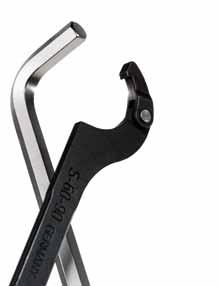
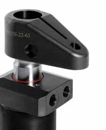
34 Built-in clamping module No. 6203L-02 Built-in clamping module, round, screw-in version Pneumatic opening. Opening operating pressure: min. 6 bar - max. 14 bar Cover and piston hardened. Repeatability < 0.02 mm. Size Pull-in/locking force up to [N] Holding force K Zero-point clamping system for set-up-time-optimized clamping with cutting and non-cutting processing in all areas, also in the food, pharmaceutical and chemical industry. The installation clamping module has high holding, pull-in and locking forces. This is opened pneumatically (1) and mechanically locked through spring force. Subsequent uncoupling of the pressure lines is possible at all times (module is tensioned pressure-free). The clamping module has one connection: 1x pneum. opening (1). For simple installation, we recommend the AMF face spanner under order On request: - Installation diagrams [N] New: shortened design Dimensions: Size dia. D dia. DN dia. D1 dia. D2 dia. D3 H HA T T1 T K M20x1,5 18 M5 38,5 2,05 4, ,45 34 INNOVATIONS 2013 ANDREAS MAIER FELLBACH


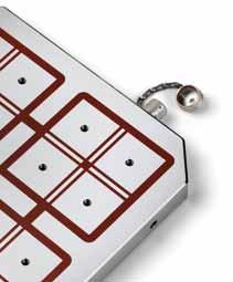
![02 mm Size Pull-in/locking force up to [N] Holding force Pneumatic 4-point clamping station with air gun valve for quick opening and closing via air gun.](/docs-images/93/112953272/images/35-3.jpg "The clamping station has two clamping grooves on the side for fastening to the machine table.")
35 4-point clamping station No. 6203PS4-001 Interchangeable pallet High-strength aluminium, anodised Size A B S SM K Interchangeable pallet for 4-point clamping station K02 with 4 clamping nipples. On request, we can incorporate mounting holes according to your specifications in the change pallet. On request: Further dimensions, actual dimensions and number of clamping nipple tips. No. 6203S4L point clamping station Main body: Aluminium, anodised Repeat accuracy <0.02 mm Size Pull-in/locking force up to [N] Holding force Pneumatic 4-point clamping station with air gun valve for quick opening and closing via air gun. The clamping station has two clamping grooves on the side for fastening to the machine table. In addition, positioning grooves for aligning on the machine table are made on the underside. The holder for a K20 clamping nipple is also provided. [N] K02 4 x x Dimensions: Size A B C F G H dia. J K S SM S SM K M ANDREAS MAIER FELLBACH INNOVATIONS

 for the status check (opened / locked).")
36 Clamping module with sensor monitor No. 6104L Clamping module with sensor monitor and mounting flange Pneumatic opening. Opening operating pressure: min. 5 bar Cover and piston hardened. Flange housing: Aluminium Repeat accuracy < mm. Zero point clamping system for automation solutions for time-optimised clamping during cutting and non-cutting machining in all sectors, as well as in the food, pharmaceutical and chemical industries. The clamping module has two inductive sensors (connection type: connector S8, cable length 150 mm) for the status check (opened / locked). This is opened pneumatically (1) and mechanically locked through spring force. The pressure line can be subsequently decoupled at any time (module is clamped depressurised). The clamping module has one connection: 1 x pneum. opening (1). On request: Size - Installation diagrams - Further automation solutions. Pull-in/locking force up to Holding force K , K ,0 [Kg] Dimensions: Size dia. DA dia. D dia. DN H HA K dia. LK dia. M dia. N H7 R K ,6 8 G1/ K ,4 8 G1/8 36 INNOVATIONS 2013 ANDREAS MAIER FELLBACH
37 Clamping module with sensor monitor No. 6105L Clamping module with sensor monitor and nipple sensing Pneumatic opening. Opening operating pressure: min. 5 bar Cover and piston hardened. Flange housing: Aluminium Repeat accuracy < mm. Size Pull-in/locking force up to Holding force K ,6 Zero point clamping system for automation solutions for time-optimised clamping during cutting and non-cutting machining in all sectors, as well as in the food, pharmaceutical and chemical industries. The clamping module has two inductive sensors (connection type: connector S8, cable length 150 mm) for the status check for opened/locked and the presence of the clamping nipple. This is pneumatically opened (1) and mechanically locked by spring force. The pressure line can be subsequently decoupled at any time (module is clamped depressurised). The clamping module has one connection: 1 x pneum. opening (1). On request: - Installation diagrams - Further automation solutions. [Kg] Dimensions: Size dia. DA dia. D dia. DN H HA K dia. LK dia. M dia. N H7 R K ,6 8 G1/8 ANDREAS MAIER FELLBACH INNOVATIONS


38 Clamping module with sensor monitor No. 6106L Clamping module with sensor monitor and nipple sensing Pneumatic opening. Opening operating pressure: min. 8 bar - max. 12 bar Re-clamping operating pressure: min. 5 bar - max. 6 bar Cover and piston hardened. Flange housing: Aluminium Repeat accuracy < mm. Size Pull-in/locking force up to Holding force K ,0 Zero point clamping system for automation solutions for time-optimised clamping during cutting and non-cutting machining in all sectors, as well as in the food, pharmaceutical and chemical industries. The clamping module has two inductive sensors (connection type: connector S8, cable length 150 mm) for the status check for opened/locked and the presence of the clamping nipple. This is pneumatically opened (1) and mechanically locked by spring force. The pressure line can be subsequently decoupled at any time (module is clamped depressurised). The clamping module has two connections: 1 x pneum. opening (1) / 1 x pneum. re-clamping (turbo) (2). On request: - Installation diagrams - Further automation solutions. [Kg] Dimensions: Size dia. DA dia. D dia. DN H HA K dia. LK dia. M dia. N H7 R K ,6 8 G1/8 38 INNOVATIONS 2013 ANDREAS MAIER FELLBACH


39 Accessories No. 6370ZN-10 Clamping nipple with colour marking for clamping module K10 Hardened, for clamping modules size K10. Size dia. DN dia. D1 dia. D2 H H1 T K10 22, K10 22, Extremely wear-resistant surface coating : Zero point nipple Gold, : Slit nipple Black. For simple, visual differentiation of the various clamping nipple types. No. 6370ZN-20 Clamping nipple with colour marking for clamping module K20 Hardened, for clamping module size K20. Size dia. DN dia. D1 dia. D2 H H1 T K20 32, K20 32, Extremely wear-resistant surface coating : Zero point nipple Gold, : Slit nipple Black For simple, visual differentiation of the various clamping nipple types. No. 6370ZN Puller Size Thread K20 M Aluminium puller is suitable for AMF K20 clamping nipple. Clamping nipples can be simply and quickly removed from the workpiece or fixture. For this purpose, the K20 puller is mounted on a pin puller and the clamping nipples are pulled out without damaging the locating bore. No. 6370ZSK-08 Air gun valve, pneumatic Max. operating pressure 10 bar. Pneumatic air gun with integrated non-return valve. For simple and quick opening of the pneumatic zero point clamping plates. When the air gun is positioned on the valve, the air pressure is released and then held by the non-return valve. Venting is effected by briefly and manually pushing the valve, which then resets under spring force. On request: - Installation diagrams Nominal bore [NW] Nominal flow [l/min] , SW ANDREAS MAIER FELLBACH INNOVATIONS
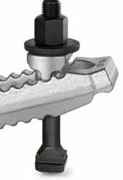
![Mechanical collet No. 6375M Mechanical collet Clamping force max.* Clamping stroke Ø Max. tightening torque [Nm] [Kg] 533281 11 0,3 40 4,5 The main body is from burnished steel.](/docs-images/93/112953272/images/40-0.jpg "The collet, which is supplied as standard, has a diameter of 99 mm and is made from anodised, high-strength aluminium. The mechanism in the main body is protected against dirt and coolant.")

40 Mechanical collet No. 6375M Mechanical collet Clamping force max.* Clamping stroke Ø Max. tightening torque [Nm] [Kg] ,3 40 4,5 The main body is from burnished steel. The collet, which is supplied as standard, has a diameter of 99 mm and is made from anodised, high-strength aluminium. The mechanism in the main body is protected against dirt and coolant. Flanged base for fastening to the machine table. Provided on the underside is the holder for the AMF K20 Zero Point system as well as grooves for positioning on AMF Zero Point clamping modules with indexing. For clamping complex workpiece contours for 5-sided machining in the machine tool. The collet is machined to the contours of the workpiece, with a minimum location depth of 2 mm. Because the clamping force is evenly applied to the component in a radial direction, the workpiece is clamped without distortion. The clamping force can be adjusted via the clamping screw, using a torque wrench for example. Consequently, especially suitable for thin-walled pipes and workpieces. Thanks to the simple collet replacement, various workpieces can be quickly and safely clamped for 5-sided machining. The collet can be milled off to 42 mm, allowing new workpiece contours to be introduced. *The max. clamping force of 11kN is introduced into the collet in an axial direction, and does not describe the radial clamping force onto the component. This varies depending on the machining height on the collet. Dimensions: dia. D dia. D1 dia. DA dia. E dia. F G H1 H2 H3 H4 K L dia. M N K7 25 M12 40 INNOVATIONS 2013 ANDREAS MAIER FELLBACH


41 Collet, single No. 6375Z-99 Collet, single Material: High-strength aluminium suitable for collet 6375M The 99 mm diameter collet is suitable for the collet element with order The collet is made from anodised, high-strength aluminium. dia. D dia. D1 Clamping stroke Ø The collet is fastened to the main element by just one centrically applied screw, and is therefore quickly replaced. The workpiece contour is milled into the collet with a minimum clamping depth of 2 mm. Because the clamping force is evenly applied to the component in a radial direction, the workpiece is clamped without distortion. The collet can be milled off to 42 mm, allowing new workpiece contours to be introduced. The maximum workpiece diameter is 90 mm. H , No. 6375Z-149 Collet, single Material: High-strength aluminium suitable for collet 6375M dia. D dia. D1 dia. D2 Clamping stroke Ø H H , The 149 mm diameter collet is suitable for the collet element with order The collet is made from anodised, high-strength aluminium. The collet is fastened to the main element by just one centrically applied screw, and is therefore quickly replaced. The workpiece contour is milled into the collet with a minimum clamping depth of 2 mm. Because the clamping force is evenly applied to the component in a radial direction, the workpiece is clamped without distortion. The collet can be milled off to 20 mm, allowing new workpiece contours to be introduced. The maximum workpiece diameter is 140 mm. ANDREAS MAIER FELLBACH INNOVATIONS


42 Adapter No. 6375A Adapter dia. D dia. D1 H ±0.01 M [Kg] M12 1,7 The adapter is made from burnished, high-quality steel. The precision slot nuts for indexing are supplied as standard. The adapter is suitable for the collet element with order and is used to position the collet system on the AMF K20.3 Zero Point clamping system with indexing, order INNOVATIONS 2013 ANDREAS MAIER FELLBACH


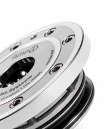
43 Zero point clamping technology to perfection + Outstanding price-performance ratio + Drastically reduced tooling time + Immediate improvement of productivity + Repeat accuracy < 5um + Stainless steel + Form fit Zero-Point-SyStemS CLAMPING. SCREWING. LOCKING. With large automation part ANDREAS MAIER FELLBACH INNOVATIONS Catalogue /19/ :24:31 AM

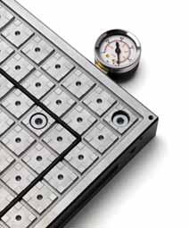
![HD [l/min] 328682 6903-30-15 6 1,5 200 300 8 1,0 2360 328708 6903-30-20 6 2,0 200 400 12 2,0 2360 328807 6903-30-28 6 2,8 178 500 15 2,2 2360 328727 6903-30-32 6 3,2 150 500 15 2,5 2360 328740](/docs-images/93/112953272/images/44-1.jpg "6930-30-40 6 4,0 125 500 14 2,0 2360 328765 6903-30-50 6 5,0 100 500 14 1,6 2360 328781 6903-30-66 6 6,6 75 500 13 1,3 2360 Flange version with O-ring seal.")


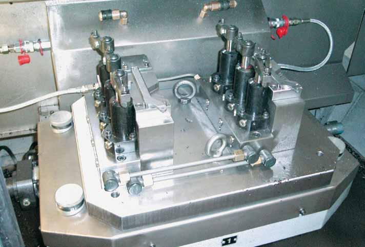
44 Hydraulic pressure booster No Hydraulic pressure booster For O-ring connection, max. operating pressure in outlet 500 bar, min. operating pressure in inlet 20 bar Hydraulic diagram: Article NG Rato i max. operating pressure ND [bar] max. operating pressure HD [bar] Q max. ND [l/min] Q max. HD [l/min] , , , , , , , , , , , , , , Flange version with O-ring seal. Hydraulic pressure boosters are used in clamping fixtures and assembly fixtures. The low pressure of the tooling machine s hydraulic system is converted into a higher operating pressure according to the transmission ratio. Input pressure and output pressure are proportional. The output pressure can be adjusted by the input pressure. Features: The most important functions are shown in the hydraulic circuit diagram (see below left). Oil is routed via the directional control valve to the IN connection and then then flows unhindered through nonreturn valves KV1 and KV2, as well as through non-return valve DV in the high-pressure range A. Under these conditions, a maximum flow through the pressure booster is achieved and a fast forward movement is generated. If input pressure IN is reached in the high-pressure area, valves KV1, KV2 and PV close. The output pressure is built up by oscillating pump unit OP. The unit switches off automatically when the final pressure has been reached in the high-pressure area A. In case of a pressure drop in the high-pressure area due to oil consumption or oil loss, pump unit OP will start automatically in order to maintain the final pressure. The pressure in the high-pressure area can be relieved via the the directly actuated pressure valve. Hole pattern shape A nominal size 6: The hydraulic oil is to be filtered to a max. nominal filter mesh of 10 µm, max. 19/16 to ISO When installing in systems in which the supply is decoupled from the pressure booster, a leak oilfree, releasable non-return valve should be installed on the high-pressure side. It must be noted that the pilot ratio of the valve must be greater than the transmission ratio of the pressure booster. The structure of the pressure booster permits a certain leakage between the IN and R connections, which must be taken into account in decoupled installations. As seen in direction of the plate. Application examples: 44 INNOVATIONS 2013 ANDREAS MAIER FELLBACH


45 FUTURE-COMPATIBLE AND ENVIRONMENTALLY CONSCIOUS AMF pump units are ahead of their time Future-compatible thanks to electric motors with higher energy efficiency classes At the end of 2009, a new EU regulation was adopted that defined, among other things, new guidelines for the environmentally-friendly design of electric motors. The goal is to reduce energy consumption and thus also CO2 emissions. On 16th June 2011 the first stage of the transition period will end and the amendment will enter into force; the second stage will follow in Our electric motors already comply with these directives, and thus also comply with the energy efficiency classes that will be required in This is attested by the Pro Energy Efficiency Initiative seal. The benefits at a glance: > energy-saving operation thanks to optimised energy-saving motor > greater efficiency > ecological operation of the pump units > future-compatible operation, compliant with the 2017 standard. The double acting solenoid valve returns to the neutral position after completion of the clamping or unclamping procedure. Advantages: > lower electricity consumption > lower temperature increase > no heat influence on the oil column in the distributors and consumers > no hazard to components due to excessive rise in pressure > no danger of injury from hand contact > no drop in magnetic force > longer useful life of the magnets 4,0 3,5 60 3,0 Temp. standard ( C) 50 Consumption (kwh) 2,5 2,0 1,5 1,0 Standard consumption (kwh) Temp. zero position ( C) Temp. at the valve ( C) 0,5 Zero position consumption (kwh) ,0 2,0 3,0 0 Test duration (days) ANDREAS MAIER FELLBACH INNOVATIONS
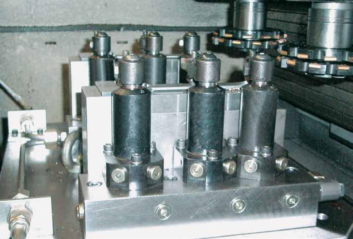
![Pump unit No. 6906N Pump unit With pressure limiting valve and electronic pressure switches, double-acting. Article Clamping circuits Q [l/min] Valve type Matching control unit Electronic control max.](/docs-images/93/112953272/images/46-0.jpg "operating pressure [bar] 328930 6906N-61666 1 2,5 4/3 6906B-2-1 160 61 328955 6906N-61616 1 2,5 4/3 6906B-2-1 400 61 [Kg] Compact, energy-saving pump unit ready for connection, electrically and")


46 Pump unit No. 6906N Pump unit With pressure limiting valve and electronic pressure switches, double-acting. Article Clamping circuits Q [l/min] Valve type Matching control unit Electronic control max. operating pressure [bar] N ,5 4/3 6906B N ,5 4/3 6906B [Kg] Compact, energy-saving pump unit ready for connection, electrically and hydraulically operational. Complete with: pressure limiting valve and pressure switch, solenoid valve, pressure gauge, float switch with temperature monitoring, oil fill, electrical control with main switch, indicator lamps and flange sockets. Electrical connection, complete with CEKON plug, pressure filter with filter mesh of 25μm. This pump unit is used predominantly as a drive and control element for single and double-acting clamping fixtures. Control method: For connection of 1-circuit control console 6906B-2-1 order Features: The radial piston pump is driven via an alternating current standard motor with the energy efficiency class IE3. The motor is protected against overload by a motor protection switch and a thermoelement. The pressure is set via a pressure limiting valve (PLV) and centralised electronic pressure switch (EPS). The pressure is set via the electronic pressure switch (EPS) in the A and B channel. They sit directly in the directional control valve. These EPS control the directional control valve in the working or zero position and output signals for switching the pump motor on and off. - High safety standard achieved through use of the 4/3-way seat valve. - Low electricity use - No heat influence on pressure generators and consumers - No undesired travel movements - In case of voltage drop or contact problems, the valve falls into the hermetically sealed middle position. - Easy triggering of external machine controllers or PLC controllers. The pump unit works in intermittent mode. If pressure drops in the A- or B-channel, the pump is automatically switched on afterward by the electronic pressure switch EDS. In case of low oil level or an increase in oil temperature, the built-in floating switch with temperature monitoring switches the pump off and the fault lamp on the electrical controller comes on. Ensure correct bleeding when connecting elements. In the event of a loss of pressure, subsequent pumping must not exceed a maximum of 2 times per minute. The pump unit must not run continuously. On request: Two, three and four clamping circuits on request. Hydraulic diagrams: Energizing both valve magnets creates a switching position that links all 4 connections to each other. A depressurised state is created that allows easy coupling. coupling unclamping position 0 clamping unclamping clamping 4/3-directional seat valve for double-acting consumers 46 INNOVATIONS 2013 ANDREAS MAIER FELLBACH
47 Pump unit Pump unit No. 6906N Hydraulic specifications: Max. operating pressure Oil capacity, reservoir Oil capacity, usable 400 bar 10 litres 4 litres Oil-flow rate 2,5 I/min Valve type 4/3 seat valve No. of hydraulic circuits 1 Hydraulic connection pipe fitting G1/4 Noise level max. 70 db(a) Ambient temp. range 10 C to + 35 C Position of use upright Pump type radial-piston pump with 3 pistons Load cycle max. 500/h Hydraulic fluid hydraulic oils HLP and HLPD according to DIN part 2 Oil recommendation HLP 22 and HLPD 22 or HLP 32 and HLPD 32 Viscosity ISO VG 22 and 32 DIN Electric specifications: Nominal voltage 400 V/50 Hz three-phase Control voltage 24 V DC Valve voltage 24 V DC Motor speed /min Sense of rotation any Motor rating 1,1 kw Pump motor Three-phase standard motor Nominal current 3 A Fuse, supply line 16 A slow-blow Fuse, control line 2 A primary, 8 A secondary Electric connection Ölflex 100; 5x1,5 mm 2 3 m long and connector CEE 16 A 6 h Protection class IP 54 Duty cycle max. 50% intermittent operation Cycle time 3 min. Hydraulic diagram: 5,0 60 4,5 4,0 Temp. standard [ C] 50 Consumption [kwh] 3,5 3,0 2,5 2,0 1,5 1,0 0,5 Temp. zero position [ C] Standard consumption [kwh] Zero position consumption [kwh] Temp. at the valve [ C] 0 0,5 1,0 1,5 2,0 2,5 3,0 0 Test duration [days] Cycle time 10 min. 4,0 3,5 60 3,0 Temp. standard [ C] 50 Consumption [kwh] 2,5 2,0 1,5 1,0 0,5 Standard consumption [kwh] Temp. zero position [ C] Zero position consumption [kwh] Temp. at the valve [ C] 0 1,0 2,0 3,0 0 Test duration [days] ANDREAS MAIER FELLBACH INNOVATIONS

48 Block cylinder with O-ring connection No. 6926D Block cylinder with O-ring connection on side double acting, max. operating pressure 500 bar, min. operating pressure 25 bar. Article Push force at 100 bar Push force at 500 bar Pull force at 100 bar Pull force at 500 bar Stroke H Vol. push [cm³] Vol. pull [cm³] Piston dia D ,0 10,0 1,2 6,0 16 3,2 1, D ,0 10,0 1,2 6, ,0 6, D ,0 10,0 1,2 6, ,0 12, D ,1 15,5 1,6 8,0 16 5,0 3, D ,1 15,5 1,6 8, ,5 10, D ,1 15,5 1,6 8, ,0 20, D ,0 25,0 2,9 14,5 20 9,8 5, D ,0 25,0 2,9 14, ,0 14, D ,0 25,0 2,9 14, ,0 29, D ,0 40,0 4,9 24, ,0 12, D ,0 40,0 4,9 24, ,0 24, D ,0 40,0 4,9 24, ,0 49, D ,5 62,5 7,6 38, ,4 19, D ,5 62,5 7,6 38, ,5 38, D ,5 62,5 7,6 38, ,0 76, D ,6 98,0 11,6 58, ,0 29, D ,6 98,0 11,6 58, ,0 58, D ,6 98,0 11,6 58, ,0 116, D ,1 155,5 18,6 93, ,5 55, D ,1 155,5 18,6 93, ,0 117, D ,1 155,5 18,6 93, ,0 186, Cylinder housing made of steel, blued. Piston and piston rod case-hardened and ground. Tandem sealing and wiper at piston rod. Piston rod with internal thread. Features: Universal mounting to fixtures through fastening holes. Each cylinder size is available with three different strokes. The block cylinders are designed with slots for keys. For applications above 160 bar operating pressure, cylinders must be tenon-blocked at slot or being backed up at cylinder body. For fixing screws must be strength class All tolerances other than specified refer to DIN ISO 2768 medium. On request: Special sizes are available on request. 48 INNOVATIONS 2013 ANDREAS MAIER FELLBACH


49 Block cylinder with O-ring connection (from stroke 50) Dimensions: Pull Pressure Article A B C dia. E F K L M N x depth dia. P Q R x T S dia. W X Y Z o-ring D ,0 M6x12 3,5 30 9,8x1,1 8 6, ,5 7x1, D ,5 6 7,0 M6x12 3,5 30 9,8x1,1 8 6, ,5 7x1, D ,5 6 7,0 M6x12 3,5 30 9,8x1,1 8 6, ,5 7x1, D ,5 M8x15 3,5 40 9,8x1,1 10 6, ,5 7x1, D ,0 7 7,5 M8x15 3,5 40 9,8x1,1 10 6, ,5 7x1, D ,0 7 7,5 M8x15 3,5 40 9,8x1,1 10 6, ,5 7x1, D ,5 M10x15 4,0 50 9,8x1,1 13 8, ,0 7x1, D ,0 7 7,5 M10x15 4,0 50 9,8x1,1 13 8, ,0 7x1, D ,0 7 7,5 M10x15 4,0 50 9,8x1,1 13 8, ,0 7x1, D ,0 M12x15 5,0 55 9,8x1, , ,0 7x1, D , ,0 M12x15 5,0 55 9,8x1, , ,0 7x1, D , ,0 M12x15 5,0 55 9,8x1, , ,0 7x1, D ,0 M16x25 6,0 63 9,8x1, , ,0 7x1, D , ,0 M16x25 6,0 63 9,8x1, , ,0 7x1, D , ,0 M16x25 6,0 63 9,8x1, , ,0 7x1, D ,0 M20x30 6, ,8x1, , ,5 8x1, D , ,0 M20x30 6, ,8x1, , ,5 8x1, D , ,0 M20x30 6, ,8x1, , ,5 8x1, D ,0 M27x40 8, ,8x1, , ,0 10x2, D , ,0 M27x40 8, ,8x1, , ,0 10x2, D , ,0 M27x40 8, ,8x1, , ,0 10x2,0 ANDREAS MAIER FELLBACH INNOVATIONS

50 Block cylinder with O-ring connection No. 6926D Block cylinder with O-ring connection on base double acting, max. operating pressure 500 bar, min. operating pressure 25 bar. Article Push force at 100 bar Push force at 500 bar Pull force at 100 bar Pull force at 500 bar Stroke H Vol. push [cm³] Vol. pull [cm³] Piston dia D ,0 10,0 1,2 6,0 16 3,2 1, D ,0 10,0 1,2 6, ,0 6, D ,0 10,0 1,2 6, ,0 12, D ,1 15,5 1,6 8,0 16 5,0 3, D ,1 15,5 1,6 8, ,5 10, D ,1 15,5 1,6 8, ,0 20, D ,0 25,0 2,9 14,5 20 9,8 5, D ,0 25,0 2,9 14, ,0 14, D ,0 25,0 2,9 14, ,0 29, D ,0 40,0 4,9 24, ,0 12, D ,0 40,0 4,9 24, ,0 24, D ,0 40,0 4,9 24, ,0 49, D ,5 62,5 7,6 38, ,4 19, D ,5 62,5 7,6 38, ,5 38, D ,5 62,5 7,6 38, ,0 76, D ,6 98,0 11,6 58, ,0 29, D ,6 98,0 11,6 58, ,0 58, D ,6 98,0 11,6 58, ,0 116, D ,1 155,5 18,6 93, ,5 55, D ,1 155,5 18,6 93, ,0 117, D ,1 155,5 18,6 93, ,0 186, Cylinder housing made of steel, blued. Piston and piston rod case-hardened and ground. Tandem sealing and wiper at piston rod. Piston rod with internal thread. Features: Universal mounting to fixtures through fastening holes. Each cylinder size is available with three different strokes. For fixing screws must be strength class All tolerances other than specified refer to DIN ISO 2768 medium. On request: Special sizes are available on request. 50 INNOVATIONS 2013 ANDREAS MAIER FELLBACH


51 Block cylinder with O-ring connection = Pull = Pressure Dimensions: Article A B C dia. E L N x depth dia. P Q R x T S U dia. W o-ring D M6x12 3,5 40 9,8x1, ,5 7x1, D M6x12 3,5 40 9,8x1, ,5 7x1, D M6x12 3,5 40 9,8x1, ,5 7x1, D M8x15 3,5 40 9,8x1, ,5 7x1, D M8x15 3,5 40 9,8x1, ,5 7x1, D M8x15 3,5 40 9,8x1, ,5 7x1, D M10x15 4,0 50 9,8x1, ,5 7x1, D M10x15 4,0 50 9,8x1, ,5 7x1, D M10x15 4,0 50 9,8x1, ,5 7x1, D M12x15 5,0 55 9,8x1, ,5 7x1, D M12x15 5,0 55 9,8x1, ,5 7x1, D M12x15 5,0 55 9,8x1, ,5 7x1, D M16x25 6,0 63 9,8x1, ,5 7x1, D M16x25 6,0 63 9,8x1, ,5 7x1, D M16x25 6,0 63 9,8x1, ,5 7x1, D M20x30 6, ,8x1, ,0 8x1, D M20x30 6, ,8x1, ,0 8x1, D M20x30 6, ,8x1, ,0 8x1, D M27x40 8, ,8x1, ,0 10x2, D M27x40 8, ,8x1, ,0 10x2, D M27x40 8, ,8x1, ,0 10x2,0 With friendly recommendation of HAAS technik GmbH, Ottenhöfen- Furschenbach ANDREAS MAIER FELLBACH INNOVATIONS
52 Block cylinder with O-ring connection No. 6926D Block cylinder with O-ring connection on rod side double acting, max. operating pressure 500 bar, min. operating pressure 25 bar. Article Push force at 100 bar Push force at 500 bar Pull force at 100 bar Pull force at 500 bar Stroke H Vol. push [cm³] Vol. pull [cm³] Piston dia D ,0 10,0 1,2 6,0 16 3,2 1, D ,0 10,0 1,2 6, ,0 6, D ,0 10,0 1,2 6, ,0 12, D ,1 15,5 1,6 8,0 16 5,0 3, D ,1 15,5 1,6 8, ,5 10, D ,1 15,5 1,6 8, ,0 20, D ,0 25,0 2,9 14,5 20 9,8 5, D ,0 25,0 2,9 14, ,0 14, D ,0 25,0 2,9 14, ,0 29, D ,0 40,0 4,9 24, ,0 12, D ,0 40,0 4,9 24, ,0 24, D ,0 40,0 4,9 24, ,0 49, D ,5 62,5 7,6 38, ,4 19, D ,5 62,5 7,6 38, ,5 38, D ,5 62,5 7,6 38, ,0 76, D ,6 98,0 11,6 58, ,0 29, D ,6 98,0 11,6 58, ,0 58, D ,6 98,0 11,6 58, ,0 116, D ,1 155,5 18,6 93, ,5 55, D ,1 155,5 18,6 93, ,0 117, D ,1 155,5 18,6 93, ,0 186, Cylinder housing made of steel, blued. Piston and piston rod case-hardened and ground. Tandem sealing and wiper at piston rod. Piston rod with internal thread. Features: Universal mounting to fixtures through fastening holes. Each cylinder size is available with three different strokes. For fixing screws must be strength class All tolerances other than specified refer to DIN ISO 2768 medium. On request: Special sizes are available on request. 52 INNOVATIONS 2013 ANDREAS MAIER FELLBACH
53 Block cylinder with O-ring connection Dimensions: Pull Pressure Article A B C dia. E L N x depth dia. P Q R x T S U dia. W o-ring D M6x12 3,5 40 9,8x1, ,5 7x1, D M6x12 3,5 40 9,8x1, ,5 7x1, D M6x12 3,5 40 9,8x1, ,5 7x1, D M8x15 3,5 40 9,8x1, ,5 7x1, D M8x15 3,5 40 9,8x1, ,5 7x1, D M8x15 3,5 40 9,8x1, ,5 7x1, D M10x15 4,0 50 9,8x1, ,5 7x1, D M10x15 4,0 50 9,8x1, ,5 7x1, D M10x15 4,0 50 9,8x1, ,5 7x1, D M12x15 5,0 55 9,8x1, ,5 7x1, D M12x15 5,0 55 9,8x1, ,5 7x1, D M12x15 5,0 55 9,8x1, ,5 7x1, D M16x25 6,0 63 9,8x1, ,5 7x1, D M16x25 6,0 63 9,8x1, ,5 7x1, D M16x25 6,0 63 9,8x1, ,5 7x1, D M20x30 6, ,8x1, ,0 8x1, D M20x30 6, ,8x1, ,0 8x1, D M20x30 6, ,8x1, ,0 8x1, D M27x40 8, ,8x1, ,0 10x2, D M27x40 8, ,8x1, ,0 10x2, D M27x40 8, ,8x1, ,0 10x2,0 ANDREAS MAIER FELLBACH INNOVATIONS

54 Swing clamp 54 INNOVATIONS 2013 ANDREAS MAIER FELLBACH

55 Swing clamp ANDREAS MAIER FELLBACH INNOVATIONS

.")

 and clamping arm weight must be observed!")

56 Swing clamps the solution for cost-effective hydraulic clamping of workpieces! Burnished body, hardened and ground piston rod. Swing clamps are delivered without clamping arm. Swing clamps are used in fixtures of all kinds, especially in applications where workpieces must be freely accessible and loaded from above. Workpieces with complex geometries can be clamped using special clamping arms (available upon request). Features: Design variants: > top flange > base flange Top and base-flange models accommodate O-ring as well as threaded hydraulic connections. The swing motion is realized by a patented ball-guide mechanism. Standard swivel angle is 90. The newly designed clamping-arm mount prevents the induction of forces into the swing mechanism during assembly. Important note: Clamping arm length, max. permissible flow rate Q max. (see diagram) and clamping arm weight must be observed! In case of a larger flow rates, a throttle/check valve must be connected upstream. The motion of the swing clamp must not be obstructed. Clamping must only be done in the vertical stroke area. Positioning: Positioning hole for clamp arm: single-acting cylinder double-acting cylinder Threaded stud Threaded stud Swing directions: Positioning hole for clamp arm: position clamped right swinging left swinging positioning hole for clamp arm (6x60 ) Threaded stud Designs: single-acting cylinder double-acting cylinder 56 INNOVATIONS 2013 ANDREAS MAIER FELLBACH
57 Benefits: > Increase in the number of balls and grooves to 3 to achieve a higher positioning accuracy and repetition accuracy. This also extends the service life. > Precise swivel angle of 90 > Increases pressing force of the balls in the swivel slot, which ensures a very precise swivel angle over a long period of use. > V-profile of the ball running groove ensures a deeper ball run in the slot wall than on the slot edge. > Improved radius transition from straight to swivel stroke. > The simple-acting models receive a stronger spring force to ensure a better return stroke. > In addition, all models receive a position-repeatable clamping arm mounting. > New materials for extending the service life of piston rod and swivel mechanism. Code of types: Type 11 = single-acting, right swinging Type 12 = single-acting, left swinging Type Type 21 = double-acting, right swinging 22 = double-acting, left swinging Swing clamp clamping force [kn] Clamping time and Q of the swing clamps 6951KP and FP Clamp arm, standard Clamp arm, long Min. allowed Q max. Min. allowed clamping time clamping time [sec.] [l/min.] [sec.] Q max. [l/min.] 2,0 0,2 0,276 0,5 0,1100 4,9 0,3 0,764 0,7 0,327 11,6 0,4 1,785 0,8 0,893 22,0 0,5 2,544 1,0 1,272 33,0 0,5 4,116 1,0 2,058 Drilling template device: Article dia, A B dia. C D dia. E F G H 6951KP-02-XX 25,5 M5 40, , KP-05-XX 36,5 M6 50, , KP-11-XX 44,5 M8 59, ,5 M8 45 Ø4 oil connection bore unclamp double-acting Ø4 oil connection bore clamp single or double-acting Article B dia. C D dia. E F G H 6951FP-02-XX M5 40, , FP-05-XX M6 50, , FP-11-XX M8 59, ,5 M8 45 Ø4 oil connection bore unclamp double-acting Ø4 oil connection bore clamp single or double-acting ANDREAS MAIER FELLBACH INNOVATIONS


58 Swing clamp No. 6951KP Swing clamp, top-flange-mounting, precision design Single-acting, max. operating pressure 350 bar, min. operating pressure 52 bar. Article Clamping force at 350 bar Sp* Clamping stroke M Total stroke N Vol. Sp [cm³] eff. piston area Sp [cm²] Q max. ** KP ,0 5,5 14,0 0,92 0,63 0, KP ,0 5,5 14,0 0,92 0,63 0, KP ,9 8,0 20,0 3,82 1,90 0, KP ,9 8,0 20,0 3,82 1,90 0, KP ,6 13,0 29,5 11,90 4,04 1, KP ,6 13,0 29,5 11,90 4,04 1, Sp = clamping, Lo = unclamp * Clamping task with clamping arm, standard **Qmax. with clamping arm, standard Hardened and burnished steel cylinder barrels. Piston rod hardened and chrome plated. Piston rod with internal thread and clamping arm positioning function. O-ring for flange seal. Stripper on the piston rod. Single acting version with return spring from stainless steel. Clamp arm not supplied as standard. The swivel clamp is used in fixtures in which the workpiece must be freely accessible and inserted from above. Even workpieces with difficult shapes can be clamped using special clamp arms (available on request). Features: Each cylinder size is available for single or double-acting operation. Oil supply via threaded connection or oil channel in the fixture body. The swing motion employs a patented ball guide mechanism. The piston stoke is executed with balls, respect Q max. volume flow. Clamping arm length and clamping arm weight must be strictly observed. When mounting accessories at the piston, no force may be applied to the piston. To equalise height differences on the workpiece, the vertical clamping path must be 50% of the clamping stroke. For single-acting cylinders, there is a risk of coolant being sucked through the breather port. In such cases the breather port has to be moved to a clean protected area via a connection line. When placing into operation, ensure that all air is bled from the system. Optionally, throttle non-return valve with G1/8 and with G1/4 can be used to throttle the oil supply. Replacement O-ring for flange connections 6951KP-02 and 6951KP-05 available under order for 6951KP-11 under order Other swivel angles are available on request. for positioning the clamping arm Ø K bore only with size 11 AC oil connection Vent screw for single-action version clamping Dimensions: Article dia. A B C D E F G dia. H J x depth dia. K L M N P dia. Q S T V X dia. Y Z AA AB o-ring AC AD KP , ,5 44,0 31, ,0 11,13 M6x7 3x6 18,0 5,5 14,0 45,0 40,0 31, , ,0 60 Ø7,65x1,78 G1/8 3, KP , ,5 44,0 31, ,0 11,13 M6x7 3x6 18,0 5,5 14,0 45,0 40,0 31, , ,0 60 Ø7,65x1,78 G1/8 3, KP , ,0 64,5 31, ,0 15,88 M10x12 3x7 17,8 8,0 20,0 57,0 50,0 33, , ,0 110 Ø7,65x1,78 G1/8 4, KP , ,0 64,5 31, ,0 15,88 M10x12 3x7 17,8 8,0 20,0 57,0 50,0 33, , ,0 110 Ø7,65x1,78 G1/8 4, KP , ,0 81,0 36, ,5 22,23 M12x13 5x9 22,1 13,0 29,5 55,5 59,5 42, , ,5 45 Ø6,0x2,0 G1/4 4, KP , ,0 81,0 36, ,5 22,23 M12x13 5x9 22,1 13,0 29,5 55,5 59,5 42, , ,5 45 Ø6,0x2,0 G1/4 4,8 58 INNOVATIONS 2013 ANDREAS MAIER FELLBACH
59 Swing clamp No. 6951KP Swing clamp, top-flange-mounting, precision design Double-acting, max. operating pressure 350 bar, min. operating pressure 35 bar. Hardened and burnished steel cylinder barrels. Piston rod hardened and chrome plated. Piston rod with internal thread and clamping arm positioning function. O-ring for flange seal. Stripper on the piston rod. Single acting version with return spring from stainless steel. Clamp arm not supplied as standard. The swivel clamp is used in fixtures in which the workpiece must be freely accessible and inserted from above. Even workpieces with difficult shapes can be clamped using special clamp arms (available on request). Features: Each cylinder size is available for single or double-acting operation. Oil supply via threaded connection or oil channel in the fixture body. The swing motion employs a patented ball guide mechanism. Article Clamping force at 350 bar Sp* Clamping force at 350 bar Lo* Clamping stroke M Total stroke N The piston stoke is executed with balls, respect Q max. volume flow. Clamping arm length and clamping arm weight must be strictly observed. When mounting accessories at the piston, no force may be applied to the piston. To equalise height differences on the workpiece, the vertical clamping path must be 50% of the clamping stroke. For single-acting cylinders, there is a risk of coolant being sucked through the breather port. In such cases the breather port has to be moved to a clean protected area via a connection line. When placing into operation, ensure that all air is bled from the system. Optionally, throttle non-return valve with G1/8 and with G1/4 can be used to throttle the oil supply. Replacement O-ring for flange connections 6951KP-02 and 6951KP-05 available under order for 6951KP-11 under order Other swivel angles are available on request. Vol. Sp [cm³] Vol. Lo [cm³] eff. piston area Sp [cm²] eff. piston area Lo [cm²] Q max. ** KP ,0 5,1 5,5 14,0 0,92 2,3 0,63 1,60 0, KP ,0 5,1 5,5 14,0 0,92 2,3 0,63 1,60 0, KP ,9 10,0 8,0 20,0 3,82 7,8 1,90 3,88 0, KP ,9 10,0 8,0 20,0 3,82 7,8 1,90 3,88 0, KP ,6 18,2 13,0 29,5 11,90 23,0 4,04 7,92 1, KP ,6 18,2 13,0 29,5 11,90 23,0 4,04 7,92 1, Sp = clamping, Lo = unclamp * Clamping task with clamping arm, standard **Qmax. with clamping arm, standard for positioning the clamping arm Ø K bore only with size 11 AC oil connection Dimensions: clamping unclamping Article dia. A B C D E F G dia. H J x depth dia. K L M N P dia. Q S T V X dia. Y Z AA AB o-ring AC AD KP , ,5 44,0 31, ,0 11,13 M6x7 3x6 18,0 5,5 14,0 45,0 40,0 31, , ,0 60 Ø7,65x1,78 G1/8 3, KP , ,5 44,0 31, ,0 11,13 M6x7 3x6 18,0 5,5 14,0 45,0 40,0 31, , ,0 60 Ø7,65x1,78 G1/8 3, KP , ,0 64,5 31, ,0 15,88 M10x12 3x7 17,8 8,0 20,0 57,0 50,0 33, , ,0 110 Ø7,65x1,78 G1/8 4, KP , ,0 64,5 31, ,0 15,88 M10x12 3x7 17,8 8,0 20,0 57,0 50,0 33, , ,0 110 Ø7,65x1,78 G1/8 4, KP , ,0 81,0 36, ,5 22,23 M12x13 5x9 22,1 13,0 29,5 55,5 59,5 42, , ,5 45 Ø6,0x2,0 G1/4 4, KP , ,0 81,0 36, ,5 22,23 M12x13 5x9 22,1 13,0 29,5 55,5 59,5 42, , ,5 45 Ø6,0x2,0 G1/4 4,8 ANDREAS MAIER FELLBACH INNOVATIONS
60 Swing clamp No. 6951FP Swing clamp, base-flange-mounting, precision design Single-acting, max. operating pressure 350 bar, min. operating pressure 52 bar. Article Clamping force at 350 bar Sp* Clamping stroke M Total stroke N Vol. Sp [cm³] eff. piston area Sp [cm²] Q max. ** FP ,0 5,5 14,0 0,92 0,63 0, FP ,0 5,5 14,0 0,92 0,63 0, FP ,9 8,0 20,0 3,82 1,90 0, FP ,9 8,0 20,0 3,82 1,90 0, FP ,6 13,0 29,5 11,90 4,04 1, FP ,6 13,0 29,5 11,90 4,04 1, Sp = clamping, Lo = unclamp * Clamping task with clamping arm, standard **Qmax. with clamping arm, standard Hardened and burnished steel cylinder barrels. Piston rod hardened and chrome plated. Piston rod with internal thread and clamping arm positioning function. O-ring for flange seal. Stripper on the piston rod. Single acting version with return spring from stainless steel. Clamp arm not supplied as standard. The swivel clamp is used in fixtures in which the workpiece must be freely accessible and inserted from above. Even workpieces with difficult shapes can be clamped using special clamp arms (available on request). Features: Each cylinder size is available for single or double-acting operation. Oil supply via threaded connection or oil channel in the fixture body. The swing motion employs a patented ball guide mechanism. The piston stoke is executed with balls, respect Q max. volume flow. Clamping arm length and clamping arm weight must be strictly observed. When mounting accessories at the piston, no force may be applied to the piston. To equalise height differences on the workpiece, the vertical clamping path must be 50% of the clamping stroke. For single-acting cylinders, there is a risk of coolant being sucked through the breather port. In such cases the breather port has to be moved to a clean protected area via a connection line. When placing into operation, ensure that all air is bled from the system. Optionally, throttle non-return valve with G1/8 and with G1/4 can be used to throttle the oil supply. Replacement O-ring for flange connection is available under No Other swivel angles are available on request. for positioning the clamping arm Ø K bore only with size 11 AC oil connection Vent screw for single-action version clamping Dimensions: Article dia. A B C D E F G dia. H J x depth dia. K M N P dia. Q S T V X dia. Y Z AA AB o-ring AC AD FP ,5 109,5 103,0 71,0 76,0 26,5 13,5 11,13 M6x7 6 5,5 14, ,0 31, , ,0 60 Ø7,65x1,78 G1/8 3, FP ,5 109,5 103,0 71,0 76,0 26,5 13,5 11,13 M6x7 6 5,5 14, ,0 31, , ,0 60 Ø7,65x1,78 G1/8 3, FP ,0 145,0 135,5 92,5 97,5 25,0 15,0 15,88 M10x12 7 8,0 20, ,0 33, , ,0 110 Ø7,65x1,78 G1/8 4, FP ,0 145,0 135,5 92,5 97,5 25,0 15,0 15,88 M10x12 7 8,0 20, ,0 33, , ,0 110 Ø7,65x1,78 G1/8 4, FP ,5 186,5 173,5 112,5 118,5 28,5 16,5 22,23 M12x ,0 29, ,4 42, , ,5 45 Ø7,65x1,78 G1/4 4, FP ,5 186,5 173,5 112,5 118,5 28,5 16,5 22,23 M12x ,0 29, ,4 42, , ,5 45 Ø7,65x1,78 G1/4 4,8 60 INNOVATIONS 2013 ANDREAS MAIER FELLBACH


61 Swing clamp No. 6951FP Swing clamp, base-flange-mounting, precision design Double-acting, max. operating pressure 350 bar, min. operating pressure 35 bar. Article Clamping force at 350 bar Sp* Clamping force at 350 bar Lo* Clamping stroke M Total stroke N Vol. Sp [cm³] Vol. Lo [cm³] eff. piston area Sp [cm²] eff. piston area Lo [cm²] Q max. ** FP ,0 5,1 5,5 14,0 0,92 2,3 0,63 1,60 0, FP ,0 5,1 5,5 14,0 0,92 2,3 0,63 1,60 0, FP ,9 10,0 8,0 20,0 3,82 7,8 1,90 3,88 0, FP ,9 10,0 8,0 20,0 3,82 7,8 1,90 3,88 0, FP ,6 18,2 13,0 29,5 11,90 23,0 4,04 7,92 1, FP ,6 18,2 13,0 29,5 11,90 23,0 4,04 7,92 1, Sp = clamping, Lo = unclamp * Clamping task with clamping arm, standard **Qmax. with clamping arm, standard Hardened and burnished steel cylinder barrels. Piston rod hardened and chrome plated. Piston rod with internal thread and clamping arm positioning function. O-ring for flange seal. Stripper on the piston rod. Single acting version with return spring from stainless steel. Clamp arm not supplied as standard. The swivel clamp is used in fixtures in which the workpiece must be freely accessible and inserted from above. Even workpieces with difficult shapes can be clamped using special clamp arms (available on request). Features: Each cylinder size is available for single or double-acting operation. Oil supply via threaded connection or oil channel in the fixture body. The swing motion employs a patented ball guide mechanism. The piston stoke is executed with balls, respect Q max. volume flow. Clamping arm length and clamping arm weight must be strictly observed. When mounting accessories at the piston, no force may be applied to the piston. To equalise height differences on the workpiece, the vertical clamping path must be 50% of the clamping stroke. For single-acting cylinders, there is a risk of coolant being sucked through the breather port. In such cases the breather port has to be moved to a clean protected area via a connection line. When placing into operation, ensure that all air is bled from the system. Optionally, throttle non-return valve with G1/8 and with G1/4 can be used to throttle the oil supply. Replacement O-ring for flange connection is available under No Other swivel angles are available on request. for positioning the clamping arm Ø K bore only with size 11 AC oil connection Dimensions: clamping unclamping Article dia. A B C D E F G dia. H J x depth dia. K M N P dia. Q S T V X dia. Y Z AA AB o-ring AC AD FP ,5 109,5 103,0 71,0 76,0 26,5 13,5 11,13 M6x7 6 5,5 14, ,0 31, , ,0 60 Ø7,65x1,78 G1/8 3, FP ,5 109,5 103,0 71,0 76,0 26,5 13,5 11,13 M6x7 6 5,5 14, ,0 31, , ,0 60 Ø7,65x1,78 G1/8 3, FP ,0 145,0 135,5 92,5 97,5 25,0 15,0 15,88 M10x12 7 8,0 20, ,0 33, , ,0 110 Ø7,65x1,78 G1/8 4, FP ,0 145,0 135,5 92,5 97,5 25,0 15,0 15,88 M10x12 7 8,0 20, ,0 33, , ,0 110 Ø7,65x1,78 G1/8 4, FP ,5 186,5 173,5 112,5 118,5 28,5 16,5 22,23 M12x ,0 29, ,4 42, , ,5 45 Ø7,65x1,78 G1/4 4, FP ,5 186,5 173,5 112,5 118,5 28,5 16,5 22,23 M12x ,0 29, ,4 42, , ,5 45 Ø7,65x1,78 G1/4 4,8 ANDREAS MAIER FELLBACH INNOVATIONS


62 Swing clamp arm No Swing Clamp Arm, standard Article for size A B C dia. E F G H J K L M N P xx-02-xx 27 9,5 4,5 11,13 +0,05 7, ,5 7,0 9,5 M6x1,00 6,5 22 M6x1, xx-05-xx 38 12,5 6,5 15,89 +0,05 10, ,0 8,0 12,7 M8x1,25 7,5 25 M8x1, xx-11-xx 51 17,5 9,5 22,24 +0,05 13, ,5 9,5 16,6 M10x1,25 12,0 25 M10x1, Tempered and blued steel. For swing clamps No. 6951xx, size 02 to 11. Clamping pressure, flow volume and clamping arm weight must be observed. Special versions available on request. No Swing Clamp Arm, upreach Article for size A B C D dia. E F G H J K L M N P xx-02-xx 32,0 19,0 5,0 5,0 11,13 +0,05 7,0 25,5 12,5 6,5 9,5 M6x1,00 12, xx-05-xx 44,5 25,5 6,5 6,5 15,89 +0,05 10,5 35,0 18,0 8,0 12,5 M8x1,25 19, xx-11-xx 63,5 35,0 9,5 9,5 22,24 +0,05 13,5 51,0 25,5 9,5 16,5 M10x1,25 26, Tempered and blued steel. For swing clamps No. 6951xx, size 02 to 11. Clamping pressure, flow volume and clamping arm weight must be observed. Special versions available on request. 62 INNOVATIONS 2013 ANDREAS MAIER FELLBACH


63 Swing clamp arm No Swing Clamp Arm, long Article for size A B C D dia. E F G H J K L xx-02-xx 82,5 26,0 10,5 8,5 11,13 +0,05 7, ,5 7,0 9,5 M6x1, xx-05-xx 136,5 33,0 14,5 12,5 15,89 +0,05 10, ,0 8,0 12,7 M8x1, xx-11-xx 162,0 50,5 19,0 16,0 22,24 +0,05 13, ,5 9,5 16,6 M10x1, Tempered and blued steel. For all swing clamps No. 6951xx, size 02 to 11 Clamping bars can be shortened to match the application.. Clamping pressure, flow volume and clamping arm weight must be observed. Special versions available on request. No Swing Clamp Arm, double ended Article for size 2A B C D dia. E F G H J K L xx-02-xx ,0 10,5 8,5 11,13 +0,05 7, ,5 7,0 9,5 M6x1, xx-05-xx ,0 14,5 12,5 15,89 +0,05 10, ,0 8,0 12,7 M8x1, xx-11-xx ,5 19,0 16,0 22,24 +0,05 13, ,5 9,5 16,6 M10x1, Tempered and blued steel. For all swing clamps No. 6951xx, size 02 to 11. Clamping bars can be shortened to match the application.. Clamping pressure, flow volume and clamping arm weight must be observed. It is also essential that clamping or support heights in either side are identical. Special versions available on request. ANDREAS MAIER FELLBACH INNOVATIONS

 must not be exceeded. Special versions are available on request. No.")
 for size A B ØC +0,05 D ØE F G ØJ K M N S ØU V -02 19,0 16 11,151 12,70 7,0 22,5 7,0 6,4 M6 2,4 30,0 2 11 9,5-05 25,5 22 15,913 18,03 11,0 27,5 8,8")
64 Accessories for swing clamp No. 6951WN Swing Clamp arm, double-ended pivoted Article for size 2A B C D dia. E F G H J dia. K L M N W max WN xx-02-xx , ,0 6 13,5 M4 M WN xx-05-xx , ,0 8 19,5 M6 M WN xx-11-xx , , ,0 M6 M Steel, blued. Clamping arm tempered. For all Series 6951 swing clamps. Used for clamping two workpieces with slightly different heights. Clamping pressure and maximum tilt angle (W) must not be exceeded. Special versions are available on request. No Dimensions for proprietary manufacturing of clamping arms Tolerance DIN ISO 2968m Important note: Lever lengths and lever weights (see 6951-xx above) must be observed! Dimensions table (proprietary manufacture) for size A B ØC +0,05 D ØE F G ØJ K M N S ØU V , ,151 12,70 7,0 22,5 7,0 6,4 M6 2,4 30, , , ,913 18,03 11,0 27,5 8,8 8,5 M8 2,9 38, , , ,263 25,40 13,5 32,5 12,0 10,5 M10 2,9 46, ,0 64 INNOVATIONS 2013 ANDREAS MAIER FELLBACH


65 Swing clamp ANDREAS MAIER FELLBACH INNOVATIONS


66 Swing clamps the solution for cost-effective hydraulic clamping of workpieces! Burnished body, hardened and ground piston rod. Swing clamps are delivered without clamping arm. Swing clamps are used in fixtures of all kinds, especially in applications where workpieces must be freely accessible and loaded from above. Workpieces with complex geometries can be clamped using special clamping arms (available upon request). Features: Design variants: > top flange > base flange Top and base-flange models accommodate O-ring as well as threaded hydraulic connections. The swing motion is realized by a patented ball-guide mechanism. Standard swivel angle is 90. The newly designed clamping-arm mount prevents the induction of forces into the swing mechanism during assembly. Important notes: Clamping arm length, max. permissible flow rate Q max. and clamping arm weight must be observed! In case of a larger flow rates, a throttle/check valve must be connected upstream. The motion of the swing clamp must not be obstructed. Clamping must only be done in the vertical stroke area. Positioning: Positioning hole for clamp arm: Single acting cylinder Double acting cylinder Threaded stud Threaded stud Swing directions: Positioning hole for clamp arm: position clamped right swinging left swinging Position of the 3 positioning holes dia. 4.8 x 90 (3x120 ) 66 INNOVATIONS 2013 ANDREAS MAIER FELLBACH


![double-acting, left swinging, extended stroke Connection options: > O-ring connection > Threaded connection Swing clamp clamping force [kn] Clamping time and Q of the swing](/docs-images/93/112953272/images/67-4.jpg "clamps 6951KP and FP Clamp arm, standard Clamp arm, long Min. allowed Q max. Min. allowed clamping time clamping time [sec.] [l/min.")
67 Benefits: > Increase in the number of balls and grooves to 3 to achieve a higher positioning accuracy and repetition accuracy. This also extends the service life. > Precise swivel angle of 90 > Increases pressing force of the balls in the swivel slot, which ensures a very precise swivel angle over a long period of use. > V-profile of the ball running groove ensures a deeper ball run in the slot wall than on the slot edge. > Improved radius transition from straight to swivel stroke. > The simple-acting models receive a stronger spring force to ensure a better return stroke. > In addition, all models receive a position-repeatable clamping arm mounting. > New materials for extending the service life of piston rod and swivel mechanism. Code of types: Type 21 = double-acting, right swinging Type 22 = double-acting, left swinging Type 210 = double-acting, right swinging, extended stroke Type 220 = double-acting, left swinging, extended stroke Connection options: > O-ring connection > Threaded connection Swing clamp clamping force [kn] Clamping time and Q of the swing clamps 6951KP and FP Clamp arm, standard Clamp arm, long Min. allowed Q max. Min. allowed clamping time clamping time [sec.] [l/min.] [sec.] Q max. [l/min.] 2,0 0,2 0,276 0,5 0,1100 4,9 0,3 0,764 0,7 0,327 11,6 0,4 1,785 0,8 0,893 22,0 0,5 2,544 1,0 1,272 33,0 0,5 4,116 1,0 2,058 ANDREAS MAIER FELLBACH INNOVATIONS

![[l/min] 327155 6951KP-22-11 22 14,5 28 21,2 7,6 2,5 2550 327163 6951KP-22-12 22 14,5 28 21,2 7,6 2,5 2550 327171 6951KP-33-11 33 16,0 30 34,3 11,4 2,5 3992 327189 6951KP-33-12 33 16,0 30 34,3 11,4](/docs-images/93/112953272/images/68-2.jpg "2,5 3992 * Clamping forces with short clamping arm. Cylinder housing made of steel, hardened and blued. Piston rod case-hardened and chrome plated. Wiper at piston rod.")
68 Swing clamp No. 6951KP Swing Clamp, top-flange-mounting single acting, max. operating pressure 350 bar, min. operating pressure 52 bar. Article Clamping force at 350 bar* Clamping stroke K Total stroke L Oil capacity [cm³] effective piston area [cm²] Q max. [l/min] KP , ,2 7,6 2, KP , ,2 7,6 2, KP , ,3 11,4 2, KP , ,3 11,4 2, * Clamping forces with short clamping arm. Cylinder housing made of steel, hardened and blued. Piston rod case-hardened and chrome plated. Wiper at piston rod. Return spring made of stainless steel. Clamp arm not included. The swing clamp is used particularly in fixtures in which the workpiecesmust be freely accessible and placed from above. Workpieces with difficult shapes can also be clamped using special clamp arms (available on request). Features: Oil supply via threaded connection or oil channel in the fixture body. The swing motion employsa ball guide mechanism. The piston is guided, and so the max. permissable oil flow rate Q max. as well as the clamping arm length and weight must be observed. When mounting accessories at the piston, no force may be applied to the piston. For single-acting cylinders, there is risk of sucking in coolant through the breather port. In such cases the breather port has to be moved to a clean protected area via a connection line. When installing, ensure that all air is bled from the system. To control the oil feed, the throttle/check valve can be optionally used. Replacement O-ring for flange connection is available under No Other swivel angles are available on request. for positioning the clamping arm E oil connection Vent screw for single-action version Dimensions: Article A B C D E F G H K L M N P Q R S T U V W Y EE o-ring KP ,8 196,0 104,5 25 G1/4 31, , ,5 14,5 27,4 35,5 35,5 27, ,5 10,7 35,1 13,0 7,65x1, KP ,8 196,0 104,5 25 G1/4 31, , ,5 14,5 27,4 35,5 35,5 27, ,5 10,7 35,1 13,0 7,65x1, KP ,0 216,5 114,0 25 G1/4 38, , ,5 18,1 35,1 44,5 44,5 35, ,0 13,5 41,4 12,5 7,65x1, KP ,0 216,5 114,0 25 G1/4 38, , ,5 18,1 35,1 44,5 44,5 35, ,0 13,5 41,4 12,5 7,65x1,78 68 INNOVATIONS 2013 ANDREAS MAIER FELLBACH

![[l/min] 327197 6951KP-22-21 22 54 14,5 28,0 21,2 43,3 7,6 15,5 2,5 2590 327205 6951KP-22-22 22 54 14,5 28,0 21,2 43,3 7,6 15,5 2,5 2590 327213 6951KP-22-210** 22 54 32,0 45,5 34,9 71,3 7,6 15,5 2,5](/docs-images/93/112953272/images/69-2.jpg "2948 327221 6951KP-22-220 22 54 32,0 45,5 34,9 71,3 7,6 15,5 2,5 2948 327239 6951KP-33-21 33 80 16,0 30,0 34,3 68,4 11,4 22,8 2,5 4355 327247 6951KP-33-22 33 80 16,0 30,0 34,3 68,4 11,4 22,8 2,5 4355")
69 Swing clamp No. 6951KP Swing Clamp, top-flange-mounting double acting, max. operating pressure 350 bar, min. operating pressure 35 bar. Article Clamping force at 350 bar Sp* Clamping force at 350 bar Lo* Clamping stroke K Total stroke L Vol. Sp [cm³] Vol. Lo [cm³] eff. piston area Sp [cm²] eff. piston area Lo [cm²] Q max. [l/min] KP ,5 28,0 21,2 43,3 7,6 15,5 2, KP ,5 28,0 21,2 43,3 7,6 15,5 2, KP ** ,0 45,5 34,9 71,3 7,6 15,5 2, KP ,0 45,5 34,9 71,3 7,6 15,5 2, KP ,0 30,0 34,3 68,4 11,4 22,8 2, KP ,0 30,0 34,3 68,4 11,4 22,8 2, KP ** ,0 46,0 52,6 105,0 11,4 22,8 2, KP ** ,0 46,0 52,6 105,0 11,4 22,8 2, Sp = clamp, Lo = unclamp * Clamping forces with short clamping arm. ** Not a stock item! Cylinder housing made of steel, hardened and blued. Piston rod case-hardened and chrome plated. Wiper at piston rod. Clamp arm not included. The swing clamp is used particularly in fixtures in which the workpiecesmust be freely accessible and placed from above. Workpieces with difficult shapes can also be clamped using special clamp arms (available on request). Features: Oil supply via threaded connection or oil channel in the fixture body. The swing motion employsa ball guide mechanism. The piston is guided, and so the max. permissable oil flow rate Q max. as well as the clamping arm length and weight must be observed. When mounting accessories at the piston, no force may be applied to the piston. When installing, ensure that all air is bled from the system. To control the oil feed, the throttle/check valve can be optionally used. Replacement O-ring for flange connection is available under No Other swivel angles are available on request. for positioning the clamping arm E oil connection J Vent screw for single-action version clamping unclamping Dimensions: Article A B C D E F G H J K L M N P Q R S T U V W Y Z AA BB DD EE o-ring KP ,8 185,5 104,5 25 G1/4 31, G1/4 14,5 28,0 33,5 14,5 27,4 35,5 35,5 27, ,5 10,7 35,1 13,0 M16 12,5 26,5 19 7,65x1, KP ,8 185,5 104,5 25 G1/4 31, G1/4 14,5 28,0 33,5 14,5 27,4 35,5 35,5 27, ,5 10,7 35,1 13,0 M16 12,5 26,5 19 7,65x1, KP ** 62,8 220,5 122,0 25 G1/4 31, G1/4 32,0 45,5 33,0 14,5 27,4 35,5 35,5 27, ,5 10,7 35,1 13,0 M16 12,5 26,5 19 7,65x1, KP ,8 220,5 122,0 25 G1/4 31, G1/4 32,0 45,5 33,0 14,5 27,4 35,5 35,5 27, ,5 10,7 35,1 13,0 M16 12,5 26,5 19 7,65x1, KP ,0 196,5 114,0 25 G1/4 38, G1/4 16,0 30,0 33,5 18,1 35,1 44,5 44,5 35, ,0 13,5 41,4 12,5 M16 12,5 32,5 19 7,65x1, KP ,0 196,5 114,0 25 G1/4 38, G1/4 16,0 30,0 33,5 18,1 35,1 44,5 44,5 35, ,0 13,5 41,4 12,5 M16 12,5 32,5 19 7,65x1, KP ** 77,0 228,5 130,0 25 G1/4 38, G1/4 32,0 46,0 33,5 18,1 35,1 44,5 44,5 35, ,0 13,5 41,4 12,5 M16 12,5 32,5 19 7,65x1, KP ** 77,0 228,5 130,0 25 G1/4 38, G1/4 32,0 46,0 33,5 18,1 35,1 44,5 44,5 35, ,0 13,5 41,4 12,5 M16 12,5 32,5 19 7,65x1,78 ANDREAS MAIER FELLBACH INNOVATIONS

![[l/min] 327270 6951FP-22-11 22 14,5 28 21,2 7,6 2,5 3030 327288 6951FP-22-12 22 14,5 28 21,2 7,6 2,5 3030 327296 6951FP-33-11 33 16,0 30 34,3 11,4 2,5 4854 327304 6951FP-33-12 33 16,0 30 34,3 11,4](/docs-images/93/112953272/images/70-2.jpg "2,5 4854 * Clamping forces with short clamping arm. Cylinder housing made of steel, hardened and blued. Piston rod case-hardened and chrome plated. Wiper at piston rod.")
70 Swing clamp No. 6951FP Swing Clamp, base-flange-mounting single acting, max. operating pressure 350 bar, min. operating pressure 52 bar. Article Clamping force at 350 bar* Clamping stroke K Total stroke L Oil capacity [cm³] effective piston area [cm²] Q max. [l/min] FP , ,2 7,6 2, FP , ,2 7,6 2, FP , ,3 11,4 2, FP , ,3 11,4 2, * Clamping forces with short clamping arm. Cylinder housing made of steel, hardened and blued. Piston rod case-hardened and chrome plated. Wiper at piston rod. Return spring made of stainless steel. Clamp arm not included. The swing clamp is used particularly in fixtures in which the workpiecesmust be freely accessible and placed from above. Workpieces with difficult shapes can also be clamped using special clamp arms (available on request). Features: Oil supply via threaded connection or oil channel in the fixture body. The swing motion employsa ball guide mechanism. The piston is guided, and so the max. permissable oil flow rate Q max. as well as the clamping arm length and weight must be observed. When mounting accessories at the piston, no force may be applied to the piston. For single-acting cylinders, there is risk of sucking in coolant through the breather port. In such cases the breather port has to be moved to a clean protected area via a connection line. When installing, ensure that all air is bled from the system. To control the oil feed, the throttle/check valve can be optionally used. Replacement O-ring for flange connection available on request under No Other swivel angles are available on request. for positioning the clamping arm E oil connection Vent screw for single-action version Dimensions: Article A B C D E F G H K L M N P Q R S T U V W Y EE o-ring FP ,8 204,0 112,0 25 G1/4 31, ,5 14, ,0 14,5 27,4 35,5 35,5 27, ,5 10,7 35,1 13,0 7,65x1, FP ,8 204,0 112,0 25 G1/4 31, ,5 14, ,0 14,5 27,4 35,5 35,5 27, ,5 10,7 35,1 13,0 7,65x1, FP ,0 224,5 121,5 25 G1/4 38, ,0 16, ,5 18,1 35,1 44,5 44,5 35, ,0 13,5 41,4 12,5 7,65x1, FP ,0 224,5 121,5 25 G1/4 38, ,0 16, ,5 18,1 35,1 44,5 44,5 35, ,0 13,5 41,4 12,5 7,65x1,78 70 INNOVATIONS 2013 ANDREAS MAIER FELLBACH

![[l/min] 327312 6951FP-22-21 22 54 14,5 28 21,2 43,3 7,6 15,5 2,5 3070 327320 6951FP-22-22 22 54 14,5 28 21,2 43,3 7,6 15,5 2,5 3070 327338 6951FP-33-21 33 80 16,0 30 34,3 68,4 11,4 22,8 2,5 4854](/docs-images/93/112953272/images/71-2.jpg "327346 6951FP-33-22 33 80 16,0 30 34,3 68,4 11,4 22,8 2,5 4854 Sp = clamp, Lo = unclamp * Clamping forces with short clamping arm. Cylinder housing made of steel, hardened and blued.")
71 Swing clamp No. 6951FP Swing Clamp, base-flange-mounting double acting, max. operating pressure 350 bar, min. operating pressure 35 bar. Article Clamping force at 350 bar Sp* Clamping force at 350 bar Lo* Clamping stroke K Total stroke L Vol. Sp [cm³] Vol. Lo [cm³] eff. piston area Sp [cm²] eff. piston area Lo [cm²] Q max. [l/min] FP , ,2 43,3 7,6 15,5 2, FP , ,2 43,3 7,6 15,5 2, FP , ,3 68,4 11,4 22,8 2, FP , ,3 68,4 11,4 22,8 2, Sp = clamp, Lo = unclamp * Clamping forces with short clamping arm. Cylinder housing made of steel, hardened and blued. Piston rod case-hardened and chrome plated. Wiper at piston rod. Clamp arm not included. The swing clamp is used particularly in fixtures in which the workpiecesmust be freely accessible and placed from above. Workpieces with difficult shapes can also be clamped using special clamp arms (available on request). Features: Oil supply via threaded connection or oil channel in the fixture body. The swing motion employsa ball guide mechanism. The piston is guided, and so the max. permissable oil flow rate Q max. as well as the clamping arm length and weight must be observed. When mounting accessories at the piston, no force may be applied to the piston. When installing, ensure that all air is bled from the system. To control the oil feed, the throttle/check valve can be optionally used. Replacement O-ring for flange connection available on request under No Other swivel angles are available on request. for positioning the clamping arm E oil connection Vent screw for single-action version clamping unclamping Dimensions: Article A B C D E F G H J K L M N P Q R S T U V W Y Z AA BB DD EE o-ring FP , ,0 25 G1/4 31, ,5 G1/4 14, ,0 14,5 27,4 35,5 35,5 27, ,5 10,7 35,1 13,0 M16 12,5 26,5 19 7,65x1, FP , ,0 25 G1/4 31, ,5 G1/4 14, ,0 14,5 27,4 35,5 35,5 27, ,5 10,7 35,1 13,0 M16 12,5 26,5 19 7,65x1, FP , ,5 25 G1/4 38, ,0 G1/4 16, ,5 18,1 35,1 44,5 44,5 35, ,0 13,5 41,4 12,5 M16 12,5 32,5 19 7,65x1, FP , ,5 25 G1/4 38, ,0 G1/4 16, ,5 18,1 35,1 44,5 44,5 35, ,0 13,5 41,4 12,5 M16 12,5 32,5 19 7,65x1,78 ANDREAS MAIER FELLBACH INNOVATIONS


72 Swing clamp arms No. 6951N Swing Clamp Arm, standard Article for size A B C dia. E F G H J K L N Z N xx-22-xx 63,5 25,5 14,5 31,75 +0,05 44,5 12,5 22,5 M16x1,5 16,0 25 0,05 M N xx-33-xx 68,0 35,0 14,2 38,11 +0,05 44,5 14,2 25,6 M16x1,5 16, M Tempered and blued steel. For swing clamps No. 6951xx, size 22 and 33. Clamping pressure, flow volume and clamping arm weight must be observed. Special versions available on request. No. 6951N Swing Clamp Arm, upreach Article for size A B C D dia. E F G H J K L M N N xx-22-xx ,5 14,5 31,75 +0,05 70,0 36,5 13,5 22,5 M16x1, ,5 38, N xx-33-xx ,3 14,3 38,11 +0,05 76,2 39,6 13,5 25,6 M16x1, ,5 41, Tempered and blued steel. For swing clamps No. 6951xx, size 22 and 33. Clamping pressure, flow volume and clamping arm weight must be observed. Special versions available on request. 72 INNOVATIONS 2013 ANDREAS MAIER FELLBACH


73 Swing clamp arms No. 6951N Swing Clamp Arm, long Article for size A B C D dia. E F G H J N L N xx-22-xx 165,0 70,5 28, ,75 +0,05 44,5 12,5 22,4 M16x1,5 0, N xx-33-xx 180,3 45,0 30, ,11 +0,05 44,5 14,2 25,5 M16x1, Tempered and blued steel. For swing clamps No. 6951xx, size 22 and 33. Clamping pressure, flow volume and clamping arm weight must be observed. Clamp arms can be shortened where necessary. Special versions available on request. No. 6951N Swing Clamp Arm, double ended Article for size A 2A B C D dia. E F G H J N xx-22-xx 140,0 280,0 70,5 28, ,75 +0,05 44,5 12,5 22,4 M16x1, N xx-33-xx 180,3 360,7 44,6 30, ,11 +0,05 44,5 14,2 25,5 M16x1, Tempered and blued steel. For swing clamps No. 6951xx, size 22 and 33. Clamping pressure, flow volume and clamping arm weight must be observed. Clamp arms can be shortened where necessary. It is also essential that clamping or support heights in either side are identical. Special versions available on request. ANDREAS MAIER FELLBACH INNOVATIONS

 must not be exceeded. Special versions are available on request. No.")
 for size A B ØC +0,025 D E ØG H J K T U V W -22 51 44,5 31,775 37,4 12,5 16,5 M16x1,50-6H 59 2,93 22,4 26 6,2 25,7-33 70")
74 Swing clamp arms No. 6951WN Swing Clamp arm, double-ended pivoted Article for size 2A B C D dia. E F G H J dia. K L M W max WN xx-22-xx , , ,5 M WN xx-33-xx , , ,0 M Steel, blued. Clamping arm tempered. For all Series 6951xx, size 22 and 33 swing clamps. Used for clamping two workpieces with slightly different heights. Clamping pressure and maximum tilt angle (W) must not be exceeded. Special versions are available on request. No Dimensions for proprietary manufacturing of clamping arms Important note: Tolerance DIN ISO 2968m Lever lengths and lever weights must be observed! Dimensions table (proprietary manufacture) for size A B ØC +0,025 D E ØG H J K T U V W ,5 31,775 37,4 12,5 16,5 M16x1,50-6H 59 2,93 22,4 26 6,2 25, ,5 38,138 40,4 14,2 16,5 M16x1,50-6H 65 3,23 25,5 26 9,6 35,5 74 INNOVATIONS 2013 ANDREAS MAIER FELLBACH
75 Important installation notes Size 02 Clamping arm length mm Max. clamping pressure bar Clamping force kn 2 0,8 0,44 Output flow l/min. 0,165 0,1 0,1 Max. clamping-arm weight g 118 Spring force* N 78 * single-acting version Size 05 Clamping arm length mm Max. clamping pressure bar Clamping force kn 5 2,2 0,88 Output flow l/min. 0,4 0,35 0,35 Max. clamping-arm weight g 354 Spring force* N 210 * single-acting version Size 11 Clamping arm length mm ,5 152 Max. clamping pressure bar Clamping force kn 11 5,1 3,0 Output flow l/min. 1,64 1,3 1,3 Max. clamping-arm weight g 807 Spring force* N 696 * single-acting version Size 22 Clamping arm length mm 63,5 101,5 152 Max. clamping pressure bar Clamping force kn ,7 Output flow l/min. 2,5 1,8 1,8 Max. clamping-arm weight g 1869 Spring force* N 943 * single-acting version Size 33 Clamping arm length mm ,5 178 Max. clamping pressure bar Clamping force kn 33,4 22,2 12 Output flow l/min. 2,5 1,7 1,0 Max. clamping-arm weight g 3311 Spring force* N 1188 * single-acting version ANDREAS MAIER FELLBACH INNOVATIONS

 Clamping-arm length (mm) No. 6951-11 No.")
 Clamping-arm length (mm) No.")
76 Swing clamp Diagram description: The diagrams show the maximum operating pressure in relation to the clamping arm length and the resulting clamping force. No No Operating pressure (bar) Clamping force (kn) Operating pressure (bar) Clamping force (kn) Clamping-arm length (mm) Clamping-arm length (mm) No No Operating pressure (bar) Clamping force (kn) Operating pressure (bar) Clamping force (kn) Clamping-arm length (mm) Clamping-arm length (mm) No Operating pressure (bar) Clamping force (kn) Clamping-arm length (mm) 76 INNOVATIONS 2013 ANDREAS MAIER FELLBACH


77 Hydraulic clamping technology ANDREAS MAIER FELLBACH INNOVATIONS
78 Vertical clamp, cartridge flange No. 6958E-XX Vertical clamp, cartridge flange Double-acting, max. operating pressure 250 bar, min. operating pressure 20 bar Article Piston force F5 at 100 bar Piston force F5 at 250 bar Vol. Sp [cm³] Vol. Lo [cm³] Piston dia. eff. piston area Sp [cm²] eff. piston area Lo [cm²] E-20 3,1 7,8 6,6 2,3 20 3,1 1, E-30 7,0 17,5 22,6 7,8 30 7,0 2, Sp = clamp, Lo = unclamp Housing made of steel, outside surface nickel-plated, piston rod hardened. Housing with two holes for connection of anti-twist protection. Two cylinder pins for anti-twist protection are enclosed unattached. Vertical clamp is especially suited for clamping fixtures in which oil is supplied through conduits drilled in the fixture body. Insert for clamping fixtures with limited space. Installation of the vertical clamp can be adjusted 360. Features: Large clamping force in the smallest installation space. Clamping lever opens 90, resulting in easy loading or removal of the workpieces, manually or by robots. The insertion bevels for the seals must not have any sharp transitions. Mill the thread up to the flat surface. Lubricate housing for mounting. On request: Other sizes available on request. Installation dimensions: Edges rounded Dimensions: Article A dia. B dia. C dia. D G H2 H3 H4 H5 H9 K N R1 dia. T V dia. W E M32x1,5 51,8 41,8 46, ,0 22, , E M48x1,5 77,0 62,0 69, ,5 33, ,54 8 Installation dimensions: Article dia. A1 B1 H7 dia. C1 H7 dia. D1 min. E1 max. F1 G H K1 L1 min. M1 max. N1 P E-20 30, ,2 47,2 M32x1,5 46,2 25 8,5 19,0 21,0 7, E-30 46, ,0 70,0 M48x1,5 69, ,0 27,5 29,5 10,0 78 INNOVATIONS 2013 ANDREAS MAIER FELLBACH


79 Accessories No. 6958E-XX-0X Steel clamping arm Case-hardened steel, for vertical clamps 6958E-XX Article Clamping force Clamping force at 100 bar at 250 bar X X1* A K R E ,38 3, E ,11 2, E ,92 2, E ,19 7, E ,56 6, E ,14 5, *X1 = Lever length at 90 No. 6958ER-XX-00 Clamping arm blank from steel Unhardened steel, for vertical clamps 6958E-XX Article X X1* A K E E *X1 = Lever length at 90 No. 6958E-XX Anti-rotation device Article E F J L M P S U E ,0 M , E ,5 M ,0 145 Made of aluminium, black anodised. Anti-rotation device mounted right or left Extra accessory: anti-rotation device ANDREAS MAIER FELLBACH INNOVATIONS


80 Centring clamp with two clamping points No Centring clamp with two clamping points Double-acting, max. operating pressure 250 bar Article Clamping force at 100 bar Clamping force at 250 bar Clamping points Clamping Ø N -1 Stroke H Repeatability Bolt Ø D ,2 8, ,0 ±0, ,2 8, ,0 ±0, ,2 8, ,0 ±0, ,0 12, ,2 ±0, ,0 12, ,2 ±0, ,0 12, ,2 ±0, Double-acting centring clamp with two clamping points. All components made of high-grade tempered and nitrated steel. For centring and clamping workpieces with machined or cast holes, cutouts or penetrations. Element screwed directly onto the fixture body, sealed with O-ring. Features: The centring clamp is fastened from below; oil is supplied through drilled channels in the fixture body. If the centring clamp is fastened from above and oil supplied through conduits drilled in the fixture body, a connection plate for O-ring connection is needed. If the centring clamp is fastened from above and oil supplied through pipes, a connection plate for pipe connection is needed. Pressure pieces are replaceable. The practical combination of 2-point and 3-point elements can avoid over-determined clamping states. Unsuitable for use on lathes. On request: Other sizes available on request. O-ring 1 groove O-ring 2 groove O-ring Dimension x1,5 0, ,17x1,78 0, x1,5 0, x2 0,2 Dimensions: Article A dia. B C dia. D -0,4 dia. E g6/h7 F G G1 J K L L1 dia. M O P R S SW dia. T dia. U dia. V W dia. X Y Y1 Z O-ring 1 O-ring , ,3 53, M6x12 M , , ,8 7,7 1,1 1,5 6 5x1,5 17,17x1, , ,3 60, M6x12 M , , ,8 7,7 1,1 1,5 6 5x1,5 17,17x1, , ,3 67, M6x12 M , , ,8 7,7 1,1 1,5 6 5x1,5 17,17x1, , ,6 75, M8x16 M ,1 0, , ,0 9,8 1,1 1,5 6 7x1,5 26x , ,6 82, M8x16 M ,1 0, , ,0 9,8 1,1 1,5 6 7x1,5 26x , ,6 89, M8x16 M ,1 0, , ,0 9,8 1,1 1,5 6 7x1,5 26x2 80 INNOVATIONS 2013 ANDREAS MAIER FELLBACH


81 Centring clamp with three clamping points No Centring clamp with three clamping points Double-acting, max. operating pressure 250 bar Article Clamping force at 100 bar Clamping force at 250 bar Clamping points Clamping Ø N -1 Stroke H Repeatability Bolt Ø D ,2 8, ,0 ±0, ,2 8, ,0 ±0, ,2 8, ,0 ±0, ,0 12, ,2 ±0, ,0 12, ,2 ±0, ,0 12, ,2 ±0, Double-acting centring clamp with three clamping points. All components made of high-grade tempered and nitrated steel. For centring and clamping workpieces with machined or cast holes, cutouts or penetrations. Element screwed directly onto the fixture body, sealed with O-ring. To fasten the centring clamp by means of an O-ring connection or pipe connection, the connection plate 6974-XXXX-X is required. Features: If the centring clamp is fastened from below, oil is supplied through conduits drilled in the fixture body. Pressure pieces are replaceable. The practical combination of 2-point and 3-point elements can avoid over-determined clamping states. Unsuitable for use on lathes. On request: Other sizes available on request. O-ring 1 groove O-ring 2 groove O-ring Dimension x1,5 0, ,17x1,78 0, x1,5 0, x2 0,2 Dimensions: Article A dia. B C dia. D -0,4 dia. E g6/h7 F G G1 J K L L1 dia. M O P R S SW dia. T dia. U dia. V W dia. X Y Y1 Z O-ring 1 O-ring , ,3 53, M6x12 M , , ,8 7,7 1,1 1,5 6 5x1,5 17,17x1, , ,3 60, M6x12 M , , ,8 7,7 1,1 1,5 6 5x1,5 17,17x1, , ,3 67, M6x12 M , , ,8 7,7 1,1 1,5 6 5x1,5 17,17x1, , ,6 75, M8x16 M ,1 0, , ,0 9,8 1,1 1,5 6 7x1,5 26x , ,6 82, M8x16 M ,1 0, , ,0 9,8 1,1 1,5 6 7x1,5 26x , ,6 89, M8x16 M ,1 0, , ,0 8,8 1,1 1,5 6 7x1,5 26x2 ANDREAS MAIER FELLBACH INNOVATIONS
82 Connection plate for centring clamp No XXXX-1 Connection plate for centring clamp for O-ring connection Article dia. AxB dia. C dia. D E F Screw (4 pieces) x15 6,6 3 24,2 14,0 M6x x17 9,0 4 32,0 18,5 M8x Tempering steel, TEM-deburred and phosphatised. If the centring clamp is fastened from above and oil is supplied through conduits drilled in the fixture body. No XXXX-2 Connection plate for centring clamp for pipeline connection Article dia. AxB dia. C dia. D E F Screw (4 pieces) x30 6,6 G1/4 24,2 14,0 M6x x30 9,0 G1/4 32,0 18,5 M8x Tempering steel, TEM-deburred and phosphatised. If the centring clamp is fastened from above and oil is supplied through pipes. 82 INNOVATIONS 2013 ANDREAS MAIER FELLBACH

83 Centring clamp ANDREAS MAIER FELLBACH INNOVATIONS

![piston area Lo [cm²] Md [Nm] 327486 6942KK-25 3,2 4,9 17,5 19,0 1,5 8,6 6,6 4,9 3,8 6,0 752 328484 6942KK-32 5,3 8,0 22,5 24,0 1,5 16,5 13,3 8,0 6,5 7,6 1098 328492 6942KK-38 7,5 11,3 24,5 26,0 1,5](/docs-images/93/112953272/images/84-1.jpg "27,8 22,9 11,3 9,3 11,0 1549 328583 6942KK-45 10,5 15,9 28,0 29,5 1,5 44,5 35,8 15,9 12,8 13,0 2362 Sp = clamp, Lo = unclamp Cylinder housing made of steel.")
.")
84 Link clamp No. 6942KK Link clamp double acting, max. operating pressure 100 bar, min. operating pressure 15 bar. Article Clamping force at 100 bar Piston force at 100 bar Clamping stroke Total stroke Extra stroke Vol. Sp [cm³] Vol. Lo [cm³] eff. piston area Sp [cm²] eff. piston area Lo [cm²] Md [Nm] KK-25 3,2 4,9 17,5 19,0 1,5 8,6 6,6 4,9 3,8 6, KK-32 5,3 8,0 22,5 24,0 1,5 16,5 13,3 8,0 6,5 7, KK-38 7,5 11,3 24,5 26,0 1,5 27,8 22,9 11,3 9,3 11, KK-45 10,5 15,9 28,0 29,5 1,5 44,5 35,8 15,9 12,8 13, Sp = clamp, Lo = unclamp Cylinder housing made of steel. Piston and hinge pins from hardened, tempered and nitrided steel. Metal wiper integrated into the housing to protect the dirt. Improved Sealings. Scope of supply includes hinge pins, tension plates, fastening screws but not clamping arm. The threaded connections are suitable for throttle/check valves XX (flow control valves). Link clamps are used in clamping fixtures in which workpieces must be freely accessible and loaded from above. Particularly suitable for clamping in clamping pockets. Features: Top-flange version, hydraulic pressure supply through threaded ports on the rear side face, or through oil ports in the flat face with O-ring seals. The horizontal standard lever centre axis and the pressure point on the workpiece are always in one plane. This prevents relative movement on the workpiece. Maximum travel speed 0.5 m/s The B to C leverage on the clamping levers is 1 to 1.5! In the design of blank levers, deviations which lead to higher clamping forces are permitted only in exceptional cases. With sizes 32 and 45, screws in strength class 12.9 must be used. Installation direction of the clamping arm: clamping unclamping Dimensions: Article Piston rod dia. Piston dia. A A1 B C D E F G G2 H H1 H2 H3 H4 I dia. K L M N O P R S U V X KK ,00 15,8 16,0 24,0 3,5 0,5 17,5 G1/8 M ,0 64,0 29, , ,0 5,5 12, ,0 67, KK ,25 13,7 18,5 28,0 3,5 2,0 21,0 G1/8 M ,5 74,5 32, , ,0 5,5 13, ,0 76, KK ,50 16,0 21,0 31,5 3,0 1,5 22,5 G1/8 M ,0 81,0 37, , ,5 6,5 16, ,5 72, KK ,00 18,7 24,5 37,0 3,0 2,5 26,5 G1/4 M ,0 96,0 43, , ,5 7,5 19, ,5 72,9 84 INNOVATIONS 2013 ANDREAS MAIER FELLBACH

![piston area Lo [cm²] Md [Nm] 327569 6942KK-25L 3,2 4,9 17,5 19,0 1,5 8,6 6,6 4,9 3,8 6,0 752 328500 6945KK-32L 5,3 8,0 22,5 24,0 1,5 16,5 13,3 8,0 6,5 7,6 1098 328518 6942KK-38L 7,5 11,3 24,5 26,0](/docs-images/93/112953272/images/85-1.jpg "1,5 27,8 22,9 11,3 9,3 11,0 1549 328609 6942KK-45L 10,5 15,9 28,0 29,5 1,5 44,5 35,8 15,9 12,8 13,0 2362 Sp = clamp, Lo = unclamp Cylinder housing made of steel.")
85 Link clamp No. 6942KK-**L Link clamp double acting, clamp arm left, max. operating pressure 100 bar, min. operating pressure 15 bar. Article Clamping force at 100 bar Piston force at 100 bar Clamping stroke Total stroke Extra stroke Vol. Sp [cm³] Vol. Lo [cm³] eff. piston area Sp [cm²] eff. piston area Lo [cm²] Md [Nm] KK-25L 3,2 4,9 17,5 19,0 1,5 8,6 6,6 4,9 3,8 6, KK-32L 5,3 8,0 22,5 24,0 1,5 16,5 13,3 8,0 6,5 7, KK-38L 7,5 11,3 24,5 26,0 1,5 27,8 22,9 11,3 9,3 11, KK-45L 10,5 15,9 28,0 29,5 1,5 44,5 35,8 15,9 12,8 13, Sp = clamp, Lo = unclamp Cylinder housing made of steel. Piston and hinge pins from hardened, tempered and nitrided steel. Metal wiper integrated into the housing to protect the dirt. Improved Sealings. Scope of supply includes hinge pins, tension plates, fastening screws but not clamping arm. The threaded connections are suitable for throttle/check valves XX (flow control valves). Link clamps are used in clamping fixtures in which workpieces must be freely accessible and loaded from above. Particularly suitable for clamping in clamping pockets. Features: Top-flange version, hydraulic pressure supply through threaded ports on the rear side face, or through oil ports in the flat face with O-ring seals. The horizontal standard lever centre axis and the pressure point on the workpiece are always in one plane. This prevents relative movement on the workpiece. Maximum travel speed 0.5 m/s The B to C leverage on the clamping levers is 1 to 1.5! In the design of blank levers, deviations which lead to higher clamping forces are permitted only in exceptional cases. With sizes 32 and 45, screws in strength class 12.9 must be used. Installation direction of the clamping arm: clamping unclamping Dimensions: Article Piston rod dia. Piston dia. A A1 B C D E F G G2 H H1 H2 H3 H4 I dia. K L M N O P R S U V X KK-25L ,00 15,8 16,0 24,0 3,5 0,5 17,5 G1/8 M ,0 64,0 29, , ,0 5,5 12, ,0 67, KK-32L ,50 16,0 21,0 31,5 3,0 1,5 22,5 G1/8 M ,5 74,5 32, , ,0 5,5 13, ,0 76, KK-38L ,50 16,0 21,0 31,5 3,0 1,5 22,5 G1/8 M ,0 81,0 37, , ,5 6,5 16, ,5 72, KK-45L ,00 18,7 24,5 37,0 3,0 2,5 26,5 G1/4 M ,0 96,0 43, , ,5 7,5 19, ,5 72,9 ANDREAS MAIER FELLBACH INNOVATIONS

![piston area Lo [cm²] Md [Nm] 327585 6942KK-25R 3,2 4,9 17,5 19,0 1,5 8,6 6,6 4,9 3,8 6,0 300 328526 6942KK-32R 5,3 8,0 22,5 24,0 1,5 16,5 13,3 8,0 6,5 7,6 1098 328534 6942KK-38R 7,5 11,3 24,5 26,0](/docs-images/93/112953272/images/86-1.jpg "1,5 27,8 22,9 11,3 9,3 11,0 1549 328625 6942KK-45R 10,5 15,9 28,0 29,5 1,5 44,5 35,8 15,9 12,8 13,0 2362 Sp = clamp, Lo = unclamp Cylinder housing made of steel.")
86 Link clamp No. 6942KK-**R Link clamp double acting, clamp arm right, max. operating pressure 100 bar, min. operating pressure 15 bar. Article Clamping force at 100 bar Piston force at 100 bar Clamping stroke Total stroke Extra stroke Vol. Sp [cm³] Vol. Lo [cm³] eff. piston area Sp [cm²] eff. piston area Lo [cm²] Md [Nm] KK-25R 3,2 4,9 17,5 19,0 1,5 8,6 6,6 4,9 3,8 6, KK-32R 5,3 8,0 22,5 24,0 1,5 16,5 13,3 8,0 6,5 7, KK-38R 7,5 11,3 24,5 26,0 1,5 27,8 22,9 11,3 9,3 11, KK-45R 10,5 15,9 28,0 29,5 1,5 44,5 35,8 15,9 12,8 13, Sp = clamp, Lo = unclamp Cylinder housing made of steel. Piston and hinge pins from hardened, tempered and nitrided steel. Metal wiper integrated into the housing to protect the dirt. Improved Sealings. Scope of supply includes hinge pins, tension plates, fastening screws but not clamping arm. The threaded connections are suitable for throttle/check valves XX (flow control valves). Link clamps are used in clamping fixtures in which workpieces must be freely accessible and loaded from above. Particularly suitable for clamping in clamping pockets. Features: Top-flange version, hydraulic pressure supply through threaded ports on the rear side face, or through oil ports in the flat face with O-ring seals. The horizontal standard lever centre axis and the pressure point on the workpiece are always in one plane. This prevents relative movement on the workpiece. Maximum travel speed 0.5 m/s The B to C leverage on the clamping levers is 1 to 1.5! In the design of blank levers, deviations which lead to higher clamping forces are permitted only in exceptional cases. With sizes 32 and 45, screws in strength class 12.9 must be used. Installation direction of the clamping arm: clamping unclamping Dimensions: Article Piston rod dia. Piston dia. A A1 B C D E F G G2 H H1 H2 H3 H4 I dia. K L M N O P R S U V X KK-25R ,00 15,8 16,0 24,0 3,5 0,5 17,5 G1/8 M ,0 64,0 29, , ,0 5,5 12, ,0 67, KK-32R ,25 13,7 18,5 28,0 3,5 2,0 21,0 G1/8 M ,5 74,5 32, , ,0 5,5 13, ,0 76, KK-38R ,50 16,0 21,0 31,5 3,0 1,5 22,5 G1/8 M ,0 81,0 37, , ,5 6,5 16, ,5 72, KK-45R ,00 18,7 24,5 37,0 3,0 2,5 26,5 G1/4 M ,0 96,0 43, , ,5 7,5 19, ,5 72,9 86 INNOVATIONS 2013 ANDREAS MAIER FELLBACH
87 Clamping arm Installation dimensions: Article G3 x depth R ±0,2 dia. T U V dia. W X1 dia. Y x max. depth KK-25 M5 x ,0 40,5 0,5 x x 0, KK-32 M5 x ,0 48,5 0,5 x x 0, KK-38 M6 x ,5 55,5 0,5 x x 0, KK-45 M6 x ,5 65,5 0,5 x x 0,1 Article G3 x depth R ±0,2 dia. T U V dia. W X1 dia. Y x max. depth KK-25L M5 x ,0 40,5 0,5 x x 0, KK-32L M5 x ,0 48,5 0,5 x x 0, KK-38L M6 x ,5 55,5 0,5 x x 0, KK-45L M6 x ,5 65,5 0,5 x x 0,1 Article G3 x depth R ±0,2 dia. T U V dia. W X1 dia. Y x max. depth KK-25R M5 x ,0 40,5 0,5 x x 0, KK-32R M5 x ,0 48,5 0,5 x x 0, KK-38R M6 x ,5 55,5 0,5 x x 0, KK-45R M6 x ,5 65,5 0,5 x x 0,1 No. 6942KL-xx-04 Clamping arm for link clamp 6942KK Article Piston force F5 at 100 bar Clamping force F1 at 100 bar B C dia. D dia. E G H H7 K L N O P R SW SW KL ,9 3,2 16,0 24, ,0 6 0,5 9,5 51,00 26,2 M4 12,0 6,00 2, KL ,0 5,3 18,5 28, ,0 8 0,5 11,5 59,25 30,2 M4 13,5 6,75 2, KL ,3 7,5 21,0 31, ,5 9 0,0 12,0 67,50 34,9 M5 16,0 8,00 2, KL ,9 10,5 24,5 37, ,5 14 1,0 17,0 80,00 39,6 M6 19,0 9,50 3, Hardened, tempered and burnished steel. Supplied with compression screw. Lever ratios must be respected. No. 6942KR-xx-04 Clamping arm blank for link clamp 6942KK Article B C dia. D dia. E G K L N P KR , ,0 9,5 65,0 40,3 12, KR , ,0 12,5 74,5 46,3 13, KR , ,5 12,0 86,0 53,4 16, KR , ,5 14,0 101,5 61,1 19,0 222 Hardened, tempered and burnished steel. Lever ratios must be respected. Formula for determining the clamping force F1: Clamping force = F1, Piston force = F5, Operating lever = B, Load lever = C F1 = F5 x B / C ANDREAS MAIER FELLBACH INNOVATIONS
88 Built-in coupling mechanism No. 6989ME Built-in coupling mechanism Article for coupling for pressurefree under pressure coupling Nominal bore [NW] max. operating pressure [bar] Coupling stroke NW 3+5 NW ME , ME , ME , ME , ME , ME ,0 56 Cylinder body and internal parts made of stainless steel. Seals from NBR, Viton, POM and PU. Couplings are used for the leakage-free connection of hydraulic oil supplies. The coupling elements are installed in a body. The sealing between coupling mechanism and nipple is axial, and installed in the coupling mechanism. If the seal is worn, it can be replaced. The coupling mechanism must always be used in combination with a nipple of the same system. Depending on the version, the couplings can be connected and disconnected at the maximum working pressure. When installed in a tank line, a coupling nipple with pressure relief must be selected. This limits the pressure that can be built up in the uncoupled state (for example due to internal leakage of the clamping elements) to approx 5 bar. When the two parts of the coupling are engaged, the pressure relief is no longer active. Features: For connection, the coupling mechanism and nipple must be axially aligned. The bodies of the two parts must be guided when the axial sealing surfaces are ca. 2-3 mm apart. The radial position tolerance must not be exceeded. The separating force due to hydraulic pressure is given by the formula NW3: F [N] = 9,4 x p [bar], NW5: F [N] = 15,4 x p [bar], NW8: F [N] = 31,4 x p [bar]. This separating force must be countered by some external, mechanical means. The coupling mechanism must seal at the bottom of the hole in which it is installed. The mounting hole must be machined to the specified accuracy and surface finish. The axial sealing surfaces must be protected from dirt. Because the coupling elements have smooth, uninterrupted sealing surfaces, the danger of them collecting dirt is reduced, and the ease with which the user can clean them before the joint is made is increased. Good results can be achieved by washing them off and blowing clean with compressed air. Positioning tolerance in axial direction for all coupling elements: +0.5 mm. Positioning tolerance in radial direction for coupling elements: +/- 0.3 mm. Permissible angle tolerance: +/- 1. On request: Other sizes available on request. Dimensions: Article dia. A dia. B C E F G H +0,1 dia. L +0,1 M dia. N dia. O S T dia. U ME ,5-9, , , ME ,5-9, , , ME ,5 2 9, , , ME ,5 2 9, , , ME ,0-15, , ,5 13,5 21, ME ,0-15, , ,5 13,5 21,5 Installation dimensions NW 3+5 NW 8 alternatively (omitted with NW3) Rounded edge alternatively Rounded edge 88 INNOVATIONS 2013 ANDREAS MAIER FELLBACH

![000 Flow resistance: 18 16 Coupling force F [N] 14.000 12.000 10.000 8.000 6.000 4.000 2.](/docs-images/93/112953272/images/89-1.jpg "000 NW 8 NW 5 NW 3 p [bar] 14 12 10 8 6 4 2 NW 3 NW 5 NW 8 0 100 200 300 400 500 Operating pressure p")

89 Built-in coupling mechanism Installation example NW 3+5 NW 8 Coupling nipple Coupling stroke Axial position tolerance Coupling mechanism Coupling force: Flow resistance: Coupling force F [N] NW 8 NW 5 NW 3 p [bar] NW 3 NW 5 NW Operating pressure p in bar 0 5 7, Flow Q [l/min.] p-characteristic with HLP 22, Viscosity 34 cst Separating force: NW 3 = F [N] = 9,4 x p [bar] NW 5 = F [N] = 15,4 x p [bar] NW 8 = F [N] = 31,4 x p [bar] Separating force ANDREAS MAIER FELLBACH INNOVATIONS
90 Built-in coupling nipple No. 6989NE Built-in coupling nipple Article for coupling under pressure for pressurefree coupling bore Nominal [NW] max. operating pressure [bar] Coupling stroke NE , NE , NE , NE , NE , NE , NE , NE ,0 60 Cylinder body and internal parts made of stainless steel. Seals from NBR, Viton, POM and PU. Couplings are used for the leakage-free connection of hydraulic oil supplies. The coupling elements are installed in a body. The sealing between coupling mechanism and nipple is axial, and installed in the coupling mechanism. If the seal is worn, it can be replaced. The coupling mechanism must always be used in combination with a nipple of the same system. Depending on the version, the couplings can be connected and disconnected at the maximum working pressure. When installed in a tank line, a coupling nipple with pressure relief must be selected. This limits the pressure that can be built up in the uncoupled state (for example due to internal leakage of the clamping elements) to approx 5 bar. When the two parts of the coupling are engaged, the pressure relief is no longer active. Features: For connection, the coupling mechanism and nipple must be axially aligned. The bodies of the two parts must be guided when the axial sealing surfaces are ca. 2-3 mm apart. The radial position tolerance must not be exceeded. The separating force due to hydraulic pressure is given by the formula NW3: F [N] = 9,4 x p [bar], NW5: F [N] = 15,4 x p [bar], NW8: F [N] = 31,4 x p [bar]. This separating force must be countered by some external, mechanical means. The coupling mechanism must seal at the bottom of the hole in which it is installed. The mounting hole must be machined to the specified accuracy and surface finish. The axial sealing surfaces must be protected from dirt. Because the coupling elements have smooth, uninterrupted sealing surfaces, the danger of them collecting dirt is reduced, and the ease with which the user can clean them before the joint is made is increased. Good results can be achieved by washing them off and blowing clean with compressed air. Positioning tolerance in axial direction for all coupling elements: +0.5 mm. Positioning tolerance in radial direction for coupling elements: +/- 0.3 mm. Permissible angle tolerance: +/- 1. On request: Other sizes available on request. Dimensions: Article dia. A dia. B C D G dia. H K L M dia. N NE ,0 11,4 25,9 9,8 10,0 4, NE ,0 11,4 25,9 9,8 10,0 4, NE ,0 11,4 26,0 13,5 10,0 4, NE ,5 17,0 38,1 13,5 16,5 4, NE ,0 11,4 26,0 13,5 10,0 4, NE ,5 17,0 38,1 13,5 16,5 4, NE ,0 15,0 31,4 18,5 9,0 7, NE ,0 15,0 31,4 18,5 9,0 7, Installation dimensions Rounded edge alternatively 90 INNOVATIONS 2013 ANDREAS MAIER FELLBACH


![000 NW 8 NW 5 NW 3 p [bar] 14 12 10 8 6 4 2 NW 3 NW 5 NW 8 0 100 200 300 400 500 Operating](/docs-images/93/112953272/images/91-2.jpg "pressure p in bar 0 5 7,5 10 15 20 25 50 Flow Q [l/min.")
91 Built-in coupling nipple Coupling nipple Coupling stroke Axial position tolerance Separating force: NW 3 = F [N] = 9,4 x p [bar] NW 5 = F [N] = 15,4 x p [bar] NW 8 = F [N] = 31,4 x p [bar] Coupling mechanism Separating force Coupling force: Flow resistance: Coupling force F [N] NW 8 NW 5 NW 3 p [bar] NW 3 NW 5 NW Operating pressure p in bar 0 5 7, Flow Q [l/min.] p-characteristic with HLP 22, Viscosity 34 cst ANDREAS MAIER FELLBACH INNOVATIONS


 / PZ Ambient temp. [ C] 339374 6916-08-10 20 3-40 - +80 300 Max. permissible pressure at connections A, B, Z = 700 bar.")

92 Check valve, pilot operated No Check valve, pilot operated for O-ring connection, max. operating pressure 700 bar. Sprung ball seat valve for plate assembly, leak oil free. Components from steel. The connection channels must be self-produced using connection plates. Sealing is via O-rings. Nomenclature of the connection channels : A = consumer, B = Pump side, Z = control, L = leak oil (relief of the valve piston chamber) For unhindered flow in one direction and blocked flow in the other direction. The blocked direction can be controlled via a control connection. The valve is used for the leak oil-free pressure maintenance on hydraulic consumers in combination with leak oil-containing directional spool valves or leak oilcontaining media penetrations. Article Q [l/min] Releasing ratio PA(B) / PZ Ambient temp. [ C] Max. permissible pressure at connections A, B, Z = 700 bar. Connection L must be depressurised to the tank. The minimum pressure for keeping the connection open is calculated from the formula pst = a x Δp + b x pb + c! Coefficients for valve : a = / b =0.03 / c = 4.8! Δp = Flow resistance and pb = pressure at connection B, see diagrams. Replacement seal: 2 x O-ring 6.07x1.78 order x O-ring 4.47x1.78 order Drilling template device: flow resistance (bar) B->A A->B control pressure (bar) volume stream Q (l/min.) pressure p (bar) 92 INNOVATIONS 2013 ANDREAS MAIER FELLBACH


93 Sequence valve and connecting plate No Sequence valve for O-ring joint, Pressure-time delayed, max. operating pressure 250 bar, min. operating pressure 30 bar. Article Q [l/min] Delay setting range [s] Direction of flow P-A 1500 Sequence valve with NG 6. Hole pattern not standard. The valve mainly consists of the housing, hydraulic piston, opening valve, throttle screw for coarse adjustment and the throttle screw for find adjustment. Oil supply takes place through drilled channels in the clamping device. With this sequence valve with timer, pressure-independent switching sequences with a defined adjustable delay within a circuit can be achieved. Parallel connection or series connection of several sequence valves is possible. Features: The compact shape makes it easier to mount on the clamping device. The hydraulic piston actuates the opening valve. Setting depends on the viscosity of the hydraulic oil. Viscosity depends on the pressure and temperature. The setting is valid for an operating mode. Pay attention to the pressure drop when the valve is opened. Observe mounting instructions with design notes for the fixture manufacturer. Replacement seal: 2 O-rings 7x Clamping procedure: 1. Cylinder 1 presses workpiece against stop a. 2. Valve opens A-line after the set time 1-10 sec. 3. Cylinder 2 and 3 run out with a time delay and press workpiece against stops b and c. Wiring diagram: Sequential control as parallel circuit. Throttle screw for coarse adjustment Adjusting screw for fine adjustment No. 6918A Connecting plate Article L x W x H Connection A x45x35 2 x G1/4 495 Steel, TEM-deburred and phosphated. For line connection of sequence valve Reduction for M5 screw for fastening on the fixture. ANDREAS MAIER FELLBACH INNOVATIONS
94 Electronic pressure switch No. 6982E Electronic pressure switch Article Measuring range [bar] Switchpoint [bar] Reset point (RP) [bar] Minimum distance Tightening between RP and SP torque [bar] [Nm] E ,5-25 0,25-24,75 0, E ,8-40 0,4-39,2 0, E , ,0-99 1, E , ,5-247,5 2, E , , , Compact electronic pressure switch with integrated 4-digit display. With two independent switching points and reverse switching points.. Stainless steel measuring cell with thin film DMS (expansion measuring strips). Screw-in thread G¼ A DIN 3852-E, 2 switch outputs. With 4-pole round plug M12 x 1 including supply lead with free end. For the electronic-hydraulic pressure monitoring in pump units and in circuits of hydraulic clamping devices. Features: The four-digit digital display can depict the pressure in bar, psi or MPa. Switching points and switch-back hystereses can be set independently. Switch-on and reset delay can be set from 0 to 99.9 seconds. Adjustable display: current pressure, peak pressure value or to switching point 1 or switching point 2. Simple handling via key programming. Device plug M12x1 4pin/5pin Nozzle Dimensions: Article Operating temperature [ C] Power supply [V DC] PNP-output switching current [A] Response time [ms] Reproducibility [%] Accuracy as per DIN [%] Protection class to DIN E ,6-32 0,25 10 ±0,5% FS max. ±1,0% FS max. IP E ,6-32 0,25 10 ±0,5% FS max. ±1,0% FS max. IP E ,6-32 0,25 10 ±0,5% FS max. ±1,0% FS max. IP E ,6-32 0,25 10 ±0,5% FS max. ±1,0% FS max. IP E ,6-32 0,25 10 ±0,5% FS max. ±1,0% FS max. IP INNOVATIONS 2013 ANDREAS MAIER FELLBACH
![AMF-Writer Slimline No. 1440WSL AMF-Writer Slimline Marking tool, suitable for 12 mm collets and Weldon holder. Needle R1 Speed [1/min] Max.](/docs-images/93/112953272/images/95-0.jpg "marking speed [m/min] 535146 90R05 0,5 0-300 200 28 535161 90R03 0,3 0-300 200 28 The tool is especially suitable for marking in highly-constricted spaces.")
 and medium line thickness on surfaces with a hardness of up to 55 HRC.")


95 AMF-Writer Slimline No. 1440WSL AMF-Writer Slimline Marking tool, suitable for 12 mm collets and Weldon holder. Needle R1 Speed [1/min] Max. marking speed [m/min] R05 0, R03 0, The tool is especially suitable for marking in highly-constricted spaces. Diverse materials such as aluminium, titanium, steel, bronze, copper, brass, plastics etc. can be marked. There are 2 needle types to choose from. - Needle 90R05 is optimally suited for marking with small font (font size of 2.5 mm legible) and medium line thickness on surfaces with a hardness of up to 55 HRC. - Needle 90R03 is optimally suited for marking with small font (font size of 1.5 mm legible) and smaller, although deeper line thickness on surfaces with a hardness of up to 57HRC. Workpiece unevenness of up to 3 mm is compensated. A marking speed of up to 200 m/min is possible, with permitted spindle rpms of The workpiece surface can be machined either dry or wet. Features: The AMF Slimline writer has high-quality guides and a robust special needle. It has an outstanding narrow tip. Setting occurs steplessly via an inside screw, which can be adjusted using a hexagon wrench. Because this tool has to be removed from the holder in order to be set, it is optimally suited for large-scale production. The tool is preferably received into 12 mm collets or Weldon holders. Advantage: - High wear resistance - Suitable for marking diverse materials - Highly-compact design - Narrow, long tip for constricted spaces (e.g. in grooves) Dimensions: D1 D2 D3 L1 L2 L3 L4 L ANDREAS MAIER FELLBACH INNOVATIONS
96 Contents By item Article Page Article Page Article Page Article Page Article Page No. 1440WSL 95 No No No No. 1610WG 8 No. 1700KSS 6 No. 6104L 36 No. 6105L 37 No. 6106L 38 No. 6203L No. 6203PS No. 6203S4L No. 6207P No. 6207S4 12 No. 6207ZN No. 6208IM 11 No. 6208M 10 No. 6210A No. 6210FN 19 No. 6210FN-M No. 6210H 28 No. 6210H No. 6210IA No. 6210IFR 18 No. 6210IH 29 No. 6210IH No. 6210IL 31 No. 6210IL No. 6210IZ 17 No. 6210L 30 No. 6210L No. 6210S 33 No. 6210S 32 No. 6210Z 16 No No ** No. 6370ZN No. 6370ZN No. 6370ZN No. 6370ZSK No. 6375A 42 No. 6375M 40 No. 6375Z No. 6375Z No No. 6906N 46 No No. 6918A No No. 6926D 50 No. 6926D 52 No. 6926D 48 No. 6942KK 84 No. 6942KK-**L 85 No. 6942KK-**R 86 No. 6942KL-xx No. 6942KR-xx No No No No No. 6951FP 60 No. 6951FP 71 No. 6951FP 70 No. 6951FP 61 No. 6951KP 58 No. 6951KP 59 No. 6951KP 68 No. 6951KP 69 No. 6951N 72 No. 6951N 73 No. 6951N 72 No. 6951N 73 No. 6951WN 74 No. 6951WN 64 No. 6958ER-XX No. 6958E-XX 78 No. 6958E-XX-0X 79 No. 6958E-XX No No No XXXX-1 82 No XXXX-2 82 No. 6982E 94 No. 6989ME 88 No. 6989NE By order Page Page Page Page Page INNOVATIONS 2013 ANDREAS MAIER FELLBACH
97 Contents By order Page Page Page Page Page In alphabetical order Description Page A Adapter 42 Adapter clamping module K5, hydr. to K10 24 Adapter clamping module K5, hydr. to K10, with indexing 25 Adapter clamping module K5, pneum. to K10 26 Adapter clamping module K5, pneum. to K10, with indexing 27 Adapter reduction from K20 to K10 22 Adapter reduction from K20 to K10, with indexing 23 Air gun valve, pneumatic 39 AMF-Writer Slimline 95 Anti-rotation device 79 Assembly element K10 and K20, hydraulic 28 Assembly element K20, hydraulic, with indexing 29 Assembly element K10, K10.3 and K20, pneumatic 30 Assembly element K10.3 and K20, pneumatic, with indexing 31 B Base element for T-grooved plate 19 Base element, with indexing for grid plates 18 Block cylinder with O-ring connection on base 50 Block cylinder with O-ring connection on rod side 52 Block cylinder with O-ring connection on side 48 Built-in clamping module, round, screw-in version 34 Built-in coupling mechanism 88 Built-in coupling nipple 90 C Cassette buffer magazine 6 Centering sleeve Ø Centring clamp with three clamping points 81 Centring clamp with two clamping points 80 Centring sleeve, cylindrical 32 Check valve, pilot operated 92 Clamping arm 87 Clamping arm blank 87 Clamping arm blank from steel 79 Clamping module, mechanical 10 Clamping module, mechanical, with indexing 11 Clamping module with sensor monitor and mounting flange 36 Clamping module with sensor monitor and sensing nipple 37, 38 Clamping nipple 13 Clamping nipple with colour marking for clamping module K10 39 Clamping nipple with colour marking for clamping module K20 39 Collet, single 41 Connecting plate 93 Connection plate for centring clamp 82 Description Page E Electronic pressure switch 94 G Gripper inserts for gripper - finger 9 Gripper inserts for gripper - prism 9 Gripper inserts for gripper - universal 9 H Hydraulic pressure booster 44 I Interchangeable pallet 13, 35 Intermediate element 16 Intermediate element, with indexing 17 L Link clamp 84, 85, 86 M Mechanical collet 40 P Puller 39 Pump unit 46 S Sequence valve 93 Spring washer for groove adapter 20 Steel clamping arm 79 Support element, adjustable ± 5 mm 33 Support element, fixed 32 Swing Clamp Arm, double ended 63, 73 Swing Clamp arm, double-ended 64, 74 Swing Clamp Arm, long 63, 73 Swing Clamp Arm, standard 62, 72 Swing Clamp Arm, upreach 62, 72 Swing Clamp, base-flange-mounting 70, 71 Swing clamp, base-flange-mounting, precision design 60, 61 Swing Clamp, top-flange-mounting 68, 69 Swing clamp, top-flange-mounting, precision design 58, 59 V Vertical clamp, cartridge flange 78 W Weldon gripper point clamping station 35 4-point clamping station, mechanical 12 ANDREAS MAIER FELLBACH INNOVATIONS

98 About AMF Products CAD-Data Service Career News Home Contact Imprint How do I order? In the Online Shop: Register at and order at the click of a mouse - simple and uncomplicated. AMF e-business offers you new possibilities! Many of our customers have been ordering AMF products electronically for several years now. Currently, for more than 30% of our sales, orders are placed electronically and processed online. In the sidebar you will find the various ordering options with which you too can profit from the advantages that AMF e-business offers. e-commerce at AMF - the AMF Online Shop In our new AMF Online Shop, AMF offers you the best conditions for your Internet buying. Its basis today is a media-neutral database from which our Online Shop and related print media are generated fully automatically. In this way you always have immediate access to the latest products and revisions. Using the direct online connection to the AMF inventory control system, you can check the availability and delivery of the goods you need, and check the current status of your order at any time. If you are a registered customer, you can log in to access your specific, individual prices and order data. Using EDIFACT: You can order direct from your inventory control system. If desired you can also receive the delivery note and invoice via EDIFACT. In format: You send us the necessary data for your order. Please ask us how it must be formatted. 1. Use the Products menu item to go to our Online Shop. 2. Register without obligation; your access data will be sent to you automatically by Study our range of products and select those you need on the individual product pages, or use Rapid registration to put them straight in the trolley. 4. go to Prices and availability to check when a product can be supplied. 5. When you order: send off your order, and you are 98% certain to receive your goods on the next working day (within Germany). 6. the entire system is supplemented and enhanced by integration of the CAD data for AMF products. These are available to our customers free of charge, in over 60 CAD formats, direct from the AMF Shop. By telephone: Just as before, all information is available from our service staff Go online with us test our website and register so that you have all these advantages. We look forward to your visit INNOVATIONS innovations 2013 ANDREAS MAIER FELLBACH
Pull-down clamps. No Low height clamping jaws, model Bulle
 Pull-down clamps The wedge action of clamping jaws is the characteristic feature of these pull down clamps. It causes the pull down effect, which presses the workpiece against both, stop and machine table.
Catalogue 2017/ / e u g o l ata C andreas Maier gmbh & Co. Kg Catalogue 2017/2018
 ZERO-POINT-SYSTEMS Catalogue 2017/2018 Company history 1890 Company founded as a lock manufacturer by Andreas Maier. 1920 Product range extended to include spanners. 1928 Production line assembly of Fellbach
Standard CATALOGUE 2018
 Standard Clamping Elements CATALOGUE 2018 Company history 1890 Company founded as a lock manufacturer by Andreas Maier. 1920 Product range extended to include spanners. 1928 Production line assembly of
WM en. Zero point clamping system SPEEDY airtec 1
 SPEEDY airtec 1 GO! Maximum productivity Using the zero point clamping system SPEEDY classic you will increase your productivity to a maximum. Adjustment and checking processes are no longer necessary
5-axis clamping system compact
 5-axis clamping system compact 395 5-axis clamping system compact Function We are setting standards with the new KIPP 5-axis clamping system compact in this field. The system was specifically designed
ZERO-POINT-SYSTEMS CLAMPING. SCREWING. LOCKING. With large automation part
 ZERO-POINT-SYSTEMS CLAMPING. SCREWING. LOCKING. With large automation part Catalogue 2012 Gross list, valid from 01.09.2011 COMPANY HISTORY 1890 Company founded by Andreas Maier as a lock manufacturer.
Zero Point Clamping System. ZERO lock BALL lock
 Zero Point Clamping System ZERO lock BALL lock kap3 kap 263 Technical information regarding ZERO lock Zero Point Clamping System Application The modularly designed, flexible ZERO lock Zero-Point Clamping
THE MOST IMPORTANT FACTS ABOUT SUPPORT BLOCKS
 THE MOST IMPORTANT FACTS ABOUT SUPPORT BLOCKS > Material: High quality tempering steel resp. castings. > Machining: All support blocks shown, have machined base- and contact faces. The serrated elements
WM en. Zero point clamping system system 3000
 Zero point clamping system system 3000 unique push-on very strong automatic monitoring flush mounted SPEEDY and spigot handling without interfering contour 50kN retention force suitable for automation
Clamping devices 521
 Clamping devices 521 522 Product overview Clamping devices Adjustable straps K0001 Hook clamps K0012 Goose-neck straps with long slot K0002 Page 526 Hook Clamps with collar K0013 Page 535 Equipped clamps
WM en. Zero point clamping system SPEEDY hydratec 1
 Zero point clamping system SPEEDY hydratec 1 GO! Maximum productivity Using the zero point clamping system SPEEDY hydratec you will increase your production times to a maximum. This clamping element stands
5-AXIS MACHINING SCS QUINTUS WWW. WORKHOLDINGSOLUTIONSGROUP. COM
 WORKHOLDING SOLUTIONS FOR -AXIS MACHINING SCS MC QUINTUS ONE system / MANY solutions WWW. WORKHOLDINGSOLUTIONSGROUP. COM MCCLAMPING S YSTEM for -axis machining MC + Quintus... MC Clamping System Free access
Clamping bolts Eccentrical cams clamping units
 2.3 Shaft Clamping bolts Eccentrical cams clamping units 2.9 2.8 2.7 2.6 2.5 2.4 2.3 2.2 2.1 2.3 Clamping bolts, Eccentrical cams, Shaft clamping units Page 641 2.3 Clamping bolts, Eccentrical cams, Shaft
IDEAL FOR 5-AXIS MACHINING
 IDEAL FOR 5-AXIS MACHINING Without additional foundations or special jaws, the RZM centric vice holds the workpiece securely and does this with a minimal interference contour. The clamping spindle is located
IDEAL FOR 5-AXIS MACHINING
 IDEAL FOR 5-AXIS MACHINING Without additional foundations or special jaws, the RZM centric vice holds the workpiece securely and does this with a minimal interference contour. The clamping spindle is located
Ensat driving tools...
 nsat driving tools... On this page, you can configure the optimum tool for your application. A configuration is provided in the following as an illustrative example. The article number is composed of two
CAM SYSTEM. Eccentric self-locking clamping devices. Set. CAM SYSTEM t. CAM SYSTEM t. Set. CAM SYSTEM s pag CAM SYSTEM s pag.
 Eccentric self-locking CAM SYSEM Set CAM SYSEM t pag. 12 CAM SYSEM t pag. 126 Set CAM SYSEM s pag. 127 CAM SYSEM s pag. 128 EDGE CLAMP pag. 130 123 CAM-SYSEM eccentric self-locking he CAM SYSEM has been
SPIETH Locknuts. Series MSW. Works Standard SN 04.03
 SPIETH Locknuts Series MSW Works Standard SN 0.03 SPIETH Locknuts Series MSW SPIETH locknuts offer a range of technical benefits, qualified by their special system and production. Under high levels of
COLLET CLOSERS, FIXTURES AND COLLETS FOR ROTATING AND FIXED APPLICATIONS
 COLLET CLOSERS, FIXTURES AND COLLETS FOR ROTATING AND FIXED APPLICATIONS ROYAL QUICK-GRIP MANUAL COLLET FIXTURES FOR 4TH AND 5TH AXIS APPLICATIONS q Unit is actuated via a hybrid mechanical/hydraulic mechanism.
PF 3000 Face Milling Cutter
 Perfection in machining PF 3000 Face Milling Cutter UHRIN YOUR WORLD-WIDE PARTNER ADVANTAES axially adjustable inserts standard tool Ø 63 250 available ex-stock reduced spindle loading thanks to light
Always a step ahead... because zero point clamping has an origin!
 Always a step ahead...... because zero point clamping has an origin! COMPACT RELIABLE FLEXIBLE STARK zero point clamping systems INNOVATIONS & SOLUTIONS www.stark-inc.com Zero point-based flexibility due
Lightweight HSC milling cutter for a perfect surface finish. flycutter - system eco
 Lightweight HSC milling cutter for a perfect surface finish flycutter - system eco 2 milling FlyCutter - System Eco mapal FlyCutter - System Eco The FlyCutter series represent a new dimension in face milling
adaptivemechanical adaptive
 Mechanical clamping elements mechanical 6 Content Product group 6 Sliding clamp, mechanical 6.2210 Clamping block, mechanical 6.2212 High-pressure spindle, mechanical with integral wedge system 6.2270
Jaw chuck B-Top3 STANDARD CHUCKS. 215 Variant. Jaw chuck B-Top3. Technical data. Size. B-Top3
 STANDARD CHUCKS. Technical data A AJ DH AI AT AW T BQ AS Size 215 ariant B-Top3 Concentricity [mm] Max. clamping force [kn] Max. axial drawtube force [kn] RPM n max. [1/min.] Stroke per jaw [mm] Ø Capacity
TOOL CLAMPING SYSTEMS
 TOOL CLAMPING SYSTEMS 2017 NEW RÖHM eshop First B2B eshop of the clamping technology industry Buy RÖHM products online 24/7 Order as a guest customer without registration Intuitive search and filter function
STAMPING TECHNOLOGY - CLAMPING RAW PARTS
 simple. gripping. future. 5-Axis 66 Makro Grip Stamping Unit 72 Stamping Unit for the workbench 73 Stamping Unit on trolley 76 Stamping Unit Accessories 77 Stamping Jaws 78 Makro Grip 5-Axis-Vices 82 5-Axis
5-Axis Machine Tools from SMW-AUTOBLOK
 5-Axis Machine Tools from SMW-AUTOBLOK 5-Axis Machine Tools ensures the following advantages: Ideal suitable for OP 10 use ST5-2G also suitable for OP 20 use Jaws with SinterGrip clamping inserts for clamping
Workpiece Clamping. Collets for Workpiece Clamping Collet Chucks for Workpiece Clamping
 Workpiece Clamping Collets for Workpiece Clamping Collet Chucks for Workpiece Clamping Overview of Contents Page Collets for Workpiece Clamping Draw-in Collets DI 2 Dead Length Collets DL 3 Emergency Dead
Example workpieces: - Gearbox casing. Example format: - Diameter 800 mm
 RADIAL CHUCKS SAV 260.99-RSF 3 + 3 JAW CHUCKS - 3 + 3 jaw chuck with two independently actuated clamping circles - Easily adaptable from centred to balanced operation - Jaw stroke 15 mm (Stroke per jaw)
Kesel Clamping Systems
 Kesel Clamping Systems CLAMPING SYSTEMS Kesel ARNO Kesel CNC Kesel NCA Kesel Bull Kesel ZS Kesel Syncroline Kesel USS Kesel Tradition and modernity A strong company, a strong group We have been at home
HEICO FASTENING SYSTEMS. Simple Fast Reliable HEICO-TEC TENSION NUT
 HEICO FASTENING SYSTEMS Simple Fast Reliable HEICO-TEC TENSION NUT WWW.HEICO-TEC.COM HEICO-TEC TENSION NUT SIMPLE FAST RELIABLE For a secure joint with a HEICO-TEC tension nut, no electric, hydraulic,
Technical features. Positive Taper Lock System for manual tool clamping. Technical features:
 clamping set Technical features The RÖHM- was specially designed for the positive taper lock clamping taking particulary into account the necessity of manual clamping. Technical features: strong design
» Modular clamping elements for optical or optical/tactical measurement» For high-precision edge measurements in reflected and transmitted light
 » Modular clamping elements for optical or optical/tactical measurement» For highprecision edge measurements in reflected and transmitted light» Toothed rails as workpiece stops or for fastening clamping
Kesel Clamping Systems
 Kesel Clamping Systems CLAMPING SYSTEMS Kesel ARNO Kesel CNC Kesel NCA Kesel Bull Kesel ZS Kesel Syncroline Kesel USS Kesel A strong company, a strong group Kesel Managing Director Martin K. Klug The people
Installation Tools. Pipe Cutters for steel and cast iron pipes 598. Deburring Reamer / for stainless steel pipes 600. for copper pipes 602
 596 597 Installation Tools Pipe Cutters for steel and cast iron pipes 598 Pipe Cutters / Pipe Deburring Reamer for stainless steel pipes 600 Pipe Cutters / Pipe Deburring Reamer / Calibrating Tool for
linear/swivel clamp CLR Operating instructions e [ ]
![linear/swivel clamp CLR Operating instructions e [ ]](/thumbs/76/73629285.jpg "linear/swivel clamp CLR Operating instructions e [ ]") linear/swivel clamp CLR en Operating instructions 8072624 2017-05e [8072626] Translation of the original instructions CLR-EN Identification of hazards and instructions on how to prevent them: Danger Immediate
linear/swivel clamp CLR en Operating instructions 8072624 2017-05e [8072626] Translation of the original instructions CLR-EN Identification of hazards and instructions on how to prevent them: Danger Immediate
The Ensat self-tapping threaded
 The nsat self-tapping threaded insert nsat is a self-tapping threaded insert with external and internal threads,cutting slots or cutting bores. A continuous process of further development has brought about
CNC EXPANDING MANDRELS
 CNC EXPANDING MANDRELS ID CLAMPING OFFERS FULL OD PART ACCESS PARALLEL EXPANSION FOR OPTIMUM ACCURACY AND GRIP FORCE LARGE RANGE IN STOCK FOR IMMEDIATE SHIPMENT ROYAL CNC EXPANDING MANDRELS Rigid and Accurate
CLAMPING TECHNOLOGY Individual special clamping tools
 CLAMPING TECHNOLOGY Individual special clamping tools 1 QUALITY SINCE 1958 Know-how, the highest quality and first class engineering. We see ourselves as a system supplier and offer our customers a full
SUMMARY. V-Lock SYSTEM BASIC ELEMENTS ACTUATORS. P V-Lock GENERAL INTRODUCTION 2. P V-Lock FIXING ELEMENTS 10 SUMMARY. P V-Lock ADAPTORS 17
 SUMMARY A3 V-Lock SYSTEM P V-Lock GENERAL INTRODUCTION 2 BASIC ELEMENTS P V-Lock FIXING ELEMENTS 10 P V-Lock ADAPTORS 17 SUMMARY P PROFILES 28 P V-Lock ACCESSORIES AND SPARE PARTS 32 1 A3 GENERAL INTRODUCTION
Machine tooling technology. Zero point clamping system SPN THE KNOW-HOW FACTORY.
 Machine tooling technology Zero point clamping system SPN THE KNOW-HOW FACTORY www.zimmer-group.com ORDER INFORMATION ZERO POINT CLAMPING SYSTEM SPN STRUCTURE OF THE ORDER NUMBER ORDER NUMBER SAMPLE SP
LIVE CENTRES FACE DRIVERS
 LIVE CENTRES FACE DRIVERS 2017 NEW RÖHM eshop First B2B eshop of the clamping technology industry Buy RÖHM products online 24/7 Order as a guest customer without registration Intuitive search and filter
STANDARD CLAMPING ELEMENTS
 STANDARD CLAMPING ELEMENTS CLAMPING. SCREWING. LOCKING. Catalogue 2011 Company history 1890 Company founded by Andreas Maier as a lock manufacturer. 1920 Production program extended to include spanners.
Vice novelties Clamping technology for NC machining. driven by technology
 Vice novelties Clamping technology for NC machining http://www.roehm.biz/schraubstockneuheiten driven by technology RKE NC-Compact vices The new NC-compact vice RKE: optimized design with proven quality.
LIVE CENTRES FACE DRIVERS
 LIVE CENTRES FACE DRIVERS 2015/2016 We work for customers who have a weakness for our strengths. Companies intent on making a difference are obliged to develop constantly as well as deploy their strengths
GF Machining Solutions. System 3R. Mecatool WEDM. Productportfolio. Version 2, valid from July 1st. 2017
 GF Machining Solutions System 3R Mecatool WEDM Productportfolio Version 2, valid from July 1st. 2017 Design and quality by System 3R Contents Zeroline...page ICS...page 7 Unimatic...page 15 Accessories...page
The Ensat self-tapping threaded insert...
 The nsat self-tapping threaded insert... nsat is a self-tapping threaded insert with external and internal thread, cutting slots or cutting bores. A continuous process of further development has brought
Centering Clamping Fixture
 Original Installation and Operating Instructions Centering Clamping Fixture 120-22424 Copyright ZEROCLAMP Centering Clamping Fixture 22424 Installation and Operating Instructions. These operating instructions
Overview Grinding Applications
 GRINDING 14E Overview Grinding Applications SRG Workpieces High precision grinding Steady Rests Grinding diameter Ø 20-85 mm Camshafts Crankshafts Shafts Chapter 1 Fine adjustment of the grinding center
Zero-Point Clamping Systems.
 www.halder.com Halder Zero-point Clamping Systems Coupling elements for clamping and at the same time centring jigs and fixtures, developed as a quick-change system for shortening set-up times. Referenced
ZeroClamp. machine tool components
 ZeroClamp machine tool components Even at a low $80 dollar hourly rate, every minute the spindle isn t turning is costing you more than $1 dollar... The tailor-made solution How do you increase machine
Compatibility overview of accessories for milling machines
 Compatibility overview of accessories for milling machines Accessories Item No. BF16 BF20/L MB4 F40E BF30 MT3 BF30 ISo30 BF46 ISO40 BF46 MT4 MF1 MT 50 MT2BV MF2 MF4 MT100 MT 200 MT 8 MX 3 MX 4 MT8 Copy
Hydraulic Clamping Systems
 Hydraulic Clamping Systems Hydraulic Swivel clamps, double action Operating pressure max. 250 bar Hydraulic swivel clamps are particularly designed for applications which require high clamping forces and
Compatibility overview of accessories for milling machines
 Compatibility overview of accessories for milling machines Accessories Item No. BF16 BF20/L MB4 F40E BF30 MT3 Copy and planing cutter head MT 2 3350212 BF30 BF46 BF46 ISo30 ISO40 MT4 MF1 MT 50 MT2BV Mf2
50, ,000 18,800 8,000. CODE 04 ER (ER ) UPC Chuck/W ITS Central Chuck. CODE 04 ER (ER ) UPC Pallet For Alignment
 UPC Chuck/W ITS Central Chuck. CODE 04 ER (ER ) UPC Pallet For Alignment") CODE 04 ER-007826 (ER-017777) UPC Pallet For Alignment CODE 04 ER-007823 (ER-016092) UPC Chuck/W ITS Central Chuck Application To align angular position and to determine the center of UPC chucks. Please
CODE 04 ER-007826 (ER-017777) UPC Pallet For Alignment CODE 04 ER-007823 (ER-016092) UPC Chuck/W ITS Central Chuck Application To align angular position and to determine the center of UPC chucks. Please
. Dimensions of the Machine Spindle Heads in Compliance with DIN The most recent editions of the DIN standards are binding.
 Clamping technology. Dimensions of the Machine Spindle Heads in Compliance with DIN The most recent editions of the DIN standards are binding. DIN 55026 Taper sizes 4 and above with drive tang. Spindle
Alufix Basic Sets offer a variety of application possibilities based on the quantity of components (from 19 to over 440) and their composition
 and their composition") ALUFIX BASIC SETS 2 ALUFIX BASIC-SETS Alufix Basic Sets offer a variety of application possibilities based on the quantity of components (from 19 to over 440) and their composition ALUFIX BASIC-SETS Note:
ALUFIX BASIC SETS 2 ALUFIX BASIC-SETS Alufix Basic Sets offer a variety of application possibilities based on the quantity of components (from 19 to over 440) and their composition ALUFIX BASIC-SETS Note:
Operating instructions. Fine boring head Ø3-88 with digital display
 Operating instructions Fine boring head Ø3-88 with digital display English 1. Basic safety information Before first use, please read the operating instructions carefully. These provide important safety
Compact technology for maximum efficiency EMCOMILL 1200 and EMCOMILL 750
 [ E[M]CONOMy] means: Compact technology for maximum efficiency EMCOMILL 1200 and EMCOMILL 750 3-axis CNC milling machines for the machining of small to medium lot sizes EMCOMILL 1200 Test UNI ISO 10791-7
LOW-PROFILE ACCU-LENGTH CNC COLLET CHUCKS
 LOW-PROFILE ACCU-LENGTH CNC COLLET CHUCKS High RPM All Royal CNC collet chucks are balanced by design for high-speed operation, and can often be run at higher speeds than conventional 3-jaw chucks because
NEWS Part. N /0 MINITEC NEWS
 NEWS 2009 Part. N 95.0423/0 MINITEC NEWS 2009 1 TABLE OF CONTENT INTRODUCTION CONTENTS 3 END CAP Z WITH HAMMER TAPS 3 END CAP 45X45 VA 4 ANGLE 25 GD-Z 4 ANGLE 45X90 GD-Z 5 ANGLE 90 GD-Z 5 HINGE 19 S 6
no mm no Dividers with scriber 150 mm NEW Square wedge-shaped knife edges on the length side
 Summer Promotion valid until 30.06.2013 all quoted prices are incl. VAT for deliveries to EU countries to customers with valid VAT-no. and for deliveries in non EU member countries the VAT is not applicable
PUSH-PULL-PROPS. and accessories ROBUSTA-GAUKEL GMBH MOUNTING TECHNOLOGY &CO.KG
 PUSH-PULL-PROPS and accessories MOUNTING TECHNOLOGY ROBUSTA-GAUKEL GMBH &CO.KG MOUNTING TECHNOLOGY PUSH-PULL-PROPS AND ACCESSORIES INDEX General information...................... 3 Push-pull-prop Type
NEW RÖHM VICE NOVELTIES. RKE-M and RZM (size 92)
") NEW RÖHM VICE NOVELTIES RKE-M and RZM (size 92) NC-COMPACT-VICE RKE-M MANUALLY OPERATED APPLICATION Particularly suitable for use on machining centers and palletisers. TYPE Clamping system mechanical without
NEW RÖHM VICE NOVELTIES RKE-M and RZM (size 92) NC-COMPACT-VICE RKE-M MANUALLY OPERATED APPLICATION Particularly suitable for use on machining centers and palletisers. TYPE Clamping system mechanical without
That s E[M]CONOMY: Big Performance for small Parts. EMCO MAXXTURN 25. Universal turning center for the complete machining of small, precision parts
![That s E[M]CONOMY: Big Performance for small Parts. EMCO MAXXTURN 25. Universal turning center for the complete machining of small, precision parts](/thumbs/76/73649244.jpg "That s E[M]CONOMY: Big Performance for small Parts. EMCO MAXXTURN 25. Universal turning center for the complete machining of small, precision parts") [ That s ] E[M]CONOMY: Big Performance for small Parts. EMCO MAXXTURN 25 Universal turning center for the complete machining of small, precision parts EMCO MAXXTURN 25 [Work area] - Spacious - Free chip
[ That s ] E[M]CONOMY: Big Performance for small Parts. EMCO MAXXTURN 25 Universal turning center for the complete machining of small, precision parts EMCO MAXXTURN 25 [Work area] - Spacious - Free chip
OIL AND GAS. Clamping technology for crude oil and natural gas industries
 OIL AND GAS Clamping technology for crude oil and natural gas industries CRUDE OIL AND NATURAL GAS - THE ENERGY OF TODAY RÖHM is the specialist for clamping technology with a wide product range, unrivaled
Portable Boring Bars
 Portable Boring Bars Because ensuring a leak-free solution is critical. It has to be Hydratight. For more than 100 years, Hydratight has provided world-class bolted joint solutions, assessing and managing
Clamping tools with flange module
 Clamping tools with flange module MAPAL clamping tools with flange module are recommended for machining conditions in which radial run-out and angular error on the machine spindle must be compensated.
KTM-16/20 TECHNICAL DATA
 TECHNICAL DATA Table Diameter : 1,600mm Max. Turning Diameter : 2,000mm Max. Turning Height : 1,750mm Table Indexing Degree : 0.001mm CNC Controller : FANUC 18i-TB ** Bed The bed has symmetrical structure
Precision Chucks for Improved Accuracy and Increased Productivity
 Precision Workholding Technology Precision Chucks for Improved Accuracy and Increased Productivity Precision Air Chucks (Self Contained Design) MicroCentric Precision Air Chucks feature a patented open
SOFTSYNCHRO HIGH PERFORMANCE TAP H O L D E R S
 SOFTSYNCHRO HIGH PERFORMANCE TAP H O L D E R S You Know Taps Now take them to the next level Triple your tap life and more with Emuge Softsynchro Tap Holders! E muge is widely recognized in the industry
Universal 5 Axis Vise Positive high strength clamping close to the work-piece Obstruction free 5-axis machining
 Machining and workholding Universal 5 Axis Vise Positive high strength clamping close to the work-piece Obstruction free 5-axis machining Obstruction free 5-side machining More and more companies are investing
Modular Clamping Rail System SL120 & SL080
 Original Installation and Operating Instructions Modular Clamping Rail System SL120 & SL080 Copyright ZEROCLAMP Modular Clamping Rail System Installation and Operating Instructions. These operating instructions
Vacuum clamping technology
 Vacuum clamping technology CLAMPING. SCREWING. LOCKING. Brochure 2014 > Vacuum clamping technology Company history 1890 Company founded as a lock manufacturer by Andreas Maier. 1920 Product range extended
MacroJunior & MacroCombi
 MacroJunior & MacroCombi gives extreme flexibility one chuck, two systems reduces setting-up times. ensures precision and quality is suitable for automatic changing with System 3R s automation program.
Operating instructions. Twin cutter boring head Ø mm
 Operating instructions Twin cutter boring head Ø23.5-153.0 mm English 1. Basic safety information Before first use, please read the operating instructions carefully. These provide important safety information
ACCESSORIES.
 Rotary, Dividing, & Cross Tables 166 Indexes 167 Dividing Heads 168 Screw Jack Sets 168 Angle Plates & V-Blocks 169 Quick Change Tool Posts & 170-171 CNC Tool Holder Bushings 171 Lathe Chucks 172-177 www.sowatool.com
Screwdriver Function Module for the automatic Screw-Assembly
 Screwdriving Technology Automation Air Motors Air Tools Screwdriver Function Module for the automatic Screw-Assembly n wide product variety for all applications n maximum ease of integration n service
HMZ Locknuts simple and reliable locking devices
 simple and reliable locking devices Technical Product Information A Member of the Schaeffler Group Application Characteristics Application The new HMZ locknuts are easy to handle, permitting accurate and
Operating instruction for the quick-change tap holders type:
 type: KSN 0 KSN 1 KSN 3 KSN 4 KSN 5 Date of edition: 01.02.2008 Stage of alteration: 1 Please keep this for future use! Contents: 1 Application range, safety instructions and technical data... 3 1.1 Application
. Dimensions of Machine Spindle Heads in Compliance with DIN The most recent editions of the DIN standards are binding
 ß Clamping tools. Dimensions of Machine Spindle Heads in Compliance with DIN The most recent editions of the DIN standards are binding DIN 5506 Taper sizes 4 and above with driver. Spindle No. of holes
STARK... always on the pulse of innovative technology
 STARK... always on the pulse of innovative technology Laser welding clamped on SPEEDY easy click STARK zero point clamping systems INNOVATIONS & SOLUTIONS Investment in future growth Cover picture Page
Repair manual. Fifth-wheel coupling JSK 38/50
 Repair manual Fifth-wheel coupling JSK 38/5 ZDE 199 3 12 E 6/212 1 Foreword Table of contents Page Fifth wheel couplings are connecting parts that must comply with very high safety requirements and must
GF Machining Solutions. System 3R palletizing systems with Spreitzer clamping solutions
 GF Machining Solutions System 3R palletizing systems with Spreitzer clamping solutions Workpiece clamping solutions to increase productivity The advantages of a palletable workpiece clamping solution //
STEVENS SUBPLATES. STEVENS ENGINEERING, INC. TOLL-FREE WEB FAX
 STEVENS SUBPLATES Spacing of hole patterns on Stevens accessories is identical to the pattern on Stevens Subplates. Insertion of the pull dowels thru bushed holes in the accessory into corresponding bushed
TAPPING CHUCKS & COLLETS
 TAPPING CHUCKS & COLLETS CAT er Tension/Compression Holders 86 CAT er Rigid Holders 86 BT er Tension/Compression Holders 87 BT er Rigid Holders 87 HSK Tension/Compression & Rigid Holders 88 NMTB er Tension/Compression
CNC TURNING CENTRES B1200-M-Y
 CNC TURNING CENTRES B1200-M-Y Great versatility and superb chip removal. B1200 2-3 The family of BIGLIA B1200 lathes universally appreciated for their rigidity, accuracy and durability, has been designed
Modular transfer system. PDF- Catalog Modular Transfer System
 Modular transfer system PDF- Catalog Modular Transfer System 1 Modular Transfer System TLM 1000 156, route de Lyon 38300 DOMARIN FRANCE Phone (33) 4 37 03 33 55 Fax (33) 4 37 03 33 59 September 2001 edition
Corporate 4-5 Introduction 6-7. Systems 8-9. System descriptions System specifications Special solutions Workpiece clamping 21-39
 Table of contents Corporate 4-5 Introduction 6-7 Systems 8-9 System descriptions 10-11 System specifications 12-13 Special solutions 14-19 Workpiece clamping 21-39 Fields of application: Turning 21-23
EROWA Wire EDM Tooling
 EROWA EROWA tooling systems make WEDM centers considerably more flexible and productive. Down-times can be virtually eliminated. Expensive machines can work round the clock. Our program contains system
QUICK, FLEXIBLE AND COPLANAR
 EASY-CLAMPING BASE BENEFITS» quick adaption» modular clamping system for various combinations» use with standard clamping systems Easy-clamping base M Easy-clamping base L Easy-clamping base XL QUICK,
VERO-S fixture membrane SPMplus Id.-No ,
 Original Operating Manual VERO-S fixture membrane SPMplus Id.-No. 0471158, 0471159 Assembly and Operating Manual Superior Clamping and Gripping Imprint Imprint Copyright: This manual remains the copyrighted
Fifth-wheel coupling JSK 38/50
 Repair manual Fifth-wheel coupling JSK 38/5 ZDE 199 3 12 E 6/25 1 LT SK38C-3 English RevA Foreword Table of contents Page Fifth wheel couplings are connecting parts that must comply with very high safety
HARDINGE Installation booklet For: Dead-Length Collet Adaptation Chucks Stationary Collet
 HARDINGE Installation booklet For: Dead-Length Collet Adaptation Chucks Stationary Collet Read the enclosed instructions and recommendations before any installations CONTENTS Dead-Length Collet Adaptation
ROYAL ULTRA-PRECISION ER COLLETS " TIR
 ROYAL C EXPANDING COLLETS q Unlike chucks and most collets that grip the OD of a workpiece, C expanding collets are designed to grip on the ID of a part. q Accu-length design ensures precise workpiece
ROEMHELD Group Program Summary
 ROEMHELD Group Program Summary PRODUCTS FOR PRODUCTIVITY Workholding elements Hydraulic cylinders Workholding systems Machine vises Zero point clamping systems Clamping power units Hydraulic components
CLAMPING SYSTEM 8000 FOR MACHINE TOOLS
 CLAMPING SYSTEM 8000 FOR MACHINE TOOLS Clamping force 60000 N Repetitive accuracy 0,002 mm Powerful, precise, economical www.hirschmanngmbh.com EN 1909 COMPANY WE ABOUT US COMPETENCE IN CLAMPING SYSTEMS
Vario Tec jaws Page 128. Vario Tec accessories Page 129. Super Vario vice Page 132. Grip Fix. Makro Grip. Quick Point. Quick Tower.
 124 jaws Page 128 accessories Page 129 Quick Point Super Vario vice Page 132 Clean Tec Quick Tower Automation Makro Grip Grip Fix A system for all common vices How does it work? The pins are blown out
Vertical and horizontal Turning/Grinding Centers
 Vertical and horizontal Turning/Grinding Centers INDEX Turning/Grinding Centers Turning and grinding of course with INDEX The INDEX Turning/Grinding Centers combine the advantages of turning and grinding
Stop and think! Tool changes are automatic but rigging, supervision and quality control are all manual operations.
 CNC Background CNC (Computer Numeric Control) is a collective term for computer controlled machine tools used in the fabrication and manufacture of parts. There are hundreds of different types of CNC machine.