Overview Grinding Applications
|
|
|
- Julia Hopkins
- 5 years ago
- Views:
Transcription


1 GRINDING 14E


2 Overview Grinding Applications SRG Workpieces High precision grinding Steady Rests Grinding diameter Ø mm Camshafts Crankshafts Shafts Chapter 1 Fine adjustment of the grinding center Retractable arms Suitable for follow down grinding High rigidity AcuGrind Workpieces High precision air chucks Chuck sizes Ø mm Bearing rings Bearing parts Bolts Camshafts Shafts Chapter 2 For OD and ID clamping Built-in pneumatic actuation For universal grinding applications Typ D Diaphragm chucks Chuck sizes Ø mm Diaphragm technology for highes precision External or pitchline clamping With or without open center Workpieces Gears Gear shafts Chapter 3 FDG High precision face drivers for machining between center pins Workpieces Camshafts Gear shafts Shafts Machining of the entire surface of the workpiece with one single operation Power operated on the side of the spindle Highest rund-out accuracy Chapter 4 CPG Pneumatic pancake cylinder for diaphragm chuck D-VARIO and face driver FDG Easy installation for grinding and turning machines without hydraulic unit Operating pressure 2-8 bar Medieum feed for air / coolant Chapter 5 EMS Workpieces Segment sleeve mandrels Clamping diameter Ø mm Bearing rings Bearing parts For ID clamping Rigid design Chapter 6


3 SRG Chapter 1 SRG High precision grinding Steady Rests Grinding diameter Ø mm Fine adjustment of the grinding center Retractable arms Suitable for follow down grinding High rigidity


 Overview Configuration Select padholder")
 Select Pad Kit Padholder for the middle piece Consisting of padholder middle piece (incl.")


4 New grinding Steady Rest with fine adjustment of the center SRG Grinding Steady Rest Application/customer benefits Support of shaft type workpieces on grinding machines Particularly suitable for the machining of crankshafts and camshafts Rapid set up of the Steady Rest to the grinding diameter due to the fine adjustment Suitable for Follow down grinding Scope of delivery Basic Grinding Steady Rest SRG Delivery in transport box (Padholder for the middle piece, Clamping Kit and Pad Kits are not scope of delivery. See therefor the overview for the configurations below.) NEW 1 2 Technical Features Horizontal fine adjustment of the grinding center 2. Vertical fine adjustment of the grinding center 3. Retractable Steady Rest arms 4. Port for compressed air against dust and coolant 5. Monitoring of end positions with standard proximity switches (switches not included) Overview Configuration Select padholder for the middle piece (SRG 1 and 2) Select clamping kit (SRG 2.1 and SRG 4) Select Pad Kit Padholder for the middle piece Consisting of padholder middle piece (incl. mounting material) 3 versions available: 0 degree, ± 5 degree, ± 7 degree Can be rotated by 180 degrees SMW-AUTOBLOK Type Basic Steady Rest Clamping range Padholder 0 degree Padholder ± 5 degree Padholder ± 7 degree Clamping kit Clamping range Clamping kit 0 degree Clamping kit ± 5 degree Clamping kit ± 7 degree Pad Kit Standard Pad Kit Special*** Id.No. mm Id.No. Id.No. Id.No. mm Id.No. Id.No. Id.No. Id.No. Id.No. SRG SRG SRG SRG * * * * Clamping Kit for the arms Consisting of 2 nests for the arms and 1 padholder for the middle piece (incl. mounting material) The different clamping ranges can be covered by different clamping kits * * I II III I II III IV ** ** ** ** ** ** ** ** ** ** ** ** ** ** ** Pad Kit Consisting of 3 pads incl. 3 mounting screws Standard for clamping range as shown on the Steady Rest Special for shifting of the clamping range -5 mm Working pressure bar Follow down grinding Yes Yes Yes Yes * Consisting of padholder for the middle piece incl. mounting material ** Consisting of padholder for the middle piece and the nests for the arms incl. mounting material *** Clamping range -5 mm
5 P2 P2 P1 P1 S1 A A R R C1 C1 E2 E2 U1 U1 U2 U2 U3 U3 E E F2 F2 I I SRG 1 Grinding Steady Rest Dimensions and technical data Monitoring of position Ø 12 mm G1/8" Port for compressed air Cylinder port G 1/4" close Cylinder port G 1/4" open E1 E1 E3 E3 S2 S2 S1 F1 F1 O1 O1 Drain O2 O2 V V D5 D5 D4 D4 D3 D3 D2 D2 D1 D1 C C J J Y Y X X H H Lift thread M8 Vertical fine adjustment K K G G Horizontal fine adjustment Subjected to technical changes For more detailed information please ask our customer service G 1/8" Port centralized lubrication SMW-AUTOBLOK Type Id. No. Minimum clamping diameter Maximum clamping diameter Clear for part loading Horizontal adjustment range Vertical adjustment range Cylinder stroke Piston area Operating pressure Working pressure Repeatability accuracy Mass SRG U1 mm 20 U2 mm 35 U3 mm 70 mm mm ± 0.20 mm mm ± 0.10 A mm C mm 55.9 C1 mm 67.5 D1 mm 22.8 D2 mm 22.7 D3 mm 22.7 D4 mm 22.7 D5 mm 22.6 E mm E1 mm 76.2 E2 mm 85.7 E3 mm 20.7 F1 mm 95.2 F2 mm 63.5 G mm 39 H mm 5 I mm 13 J mm K mm 16 O1 mm 4.5 O2 mm P1 mm 41 P2 mm 35 R mm 82.8 S1 mm 11 S2 mm 13.5 T mm 39 V mm 37 X mm 19.5 Y mm 19.5 mm 69.9 cm² 6.38 max bar 45 bar mm kg 8.7
6 A R C1 E2 P2 P1 U1 U2 U3 E1 E F2 I SRG 2 Dimensions and technical data Grinding Steady Rest Monitoring of position Ø 12 mm G1/8" Port for compressed air Cylinder port G 1/4" close F1 Cylinder port G 1/4" open O1 Drain O2 S V D4 D3 D2 D1 C J Vertical fine adjustment Horizontal fine adjustment X Y H Lift thread M8 T K G Subjected to technical changes For more detailed information please ask our customer service G 1/8" Port centralized lubrication SMW-AUTOBLOK Type Id. No. Minimum clamping diameter Maximum clamping diameter Clear for part loading Horizontal adjustment range Vertical adjustment range Cylinder stroke Piston area Operating pressure Working pressure Repeatability accuracy Mass SRG U1 mm 30 U2 mm 60 U4 mm 80 mm mm ± 0.20 mm mm ± 0.14 A mm C mm 79 C1 mm 88.4 D1 mm 31.8 D2 mm 27.4 D3 mm 27.3 D4 mm 31.7 E mm E1 mm 84.1 E2 mm 23.8 F1 mm 95.2 F2 mm 71 G mm 45 H mm 5 I mm 13 J mm K mm 19 M mm 41 O1 mm 4.5 O2 mm P1 mm 42 P2 mm 35 R mm 94.7 S mm 13.5 T mm 45 V mm 42 X mm 13 Y mm 19 mm 73.4 cm² 7,07 max bar 45 bar mm kg 11.8
7 A A R R C1 C1 E1 E1 P2 P1 P2 P1 U1 U2 U1 U2 U3 U3 E E F2 F2 I I SRG 2.1 Grinding Steady Rest Dimensions and technical data Monitoring of position Ø 12 mm G1/8" Port for compressed air Cylinder port G 1/4" close E2 E2 F1 F1 Cylinder port G 1/4" open O1 O1 Drain O2 O2 Lift thread M8 S S D4 D4 D3 D3 D2 D2 D1 D1 C C J J V V Vertical fine adjustment Horizontal fine adjustment X X Y Y H H T T K K G G Subjected to technical changes For more detailed information please ask our customer service G 1/8" Port centralized lubrication SMW-AUTOBLOK Type Id.No. Minimum clamping diameter Maximum clamping diameter Clear for part loading Horizontal adjustment range Vertical adjustment range Cylinder stroke Piston area Operating pressure Working pressure Repeatability accuracy Mass Modular nests for the arms: (*) mm clamping range by using clamping kit I (**) mm clamping range by using clamping kit II (***) mm clamping range by using clamping kit III SRG U1 mm 12 * 28 ** 44 *** U2 mm 28 * 44 ** 60 *** U3 mm 30 * 46 ** 62 *** mm mm ± 0.20 mm mm ± 0.14 A mm C mm 79 C1 mm 88.4 D1 mm 31.8 D2 mm 27.4 D3 mm 27.3 D4 mm 31.7 E mm E1 mm 84.1 E2 mm 23.8 F1 mm 95.2 F2 mm 71 G mm 45 H mm 5 I mm 13 J mm K mm 19 M mm 41 O1 mm 4.5 O2 mm P1 mm 42 P2 mm 35 R mm 94.7 S mm 13.5 T mm 45 V mm 42 X mm 13 Y mm 19 mm 66.4 cm² 7,07 bar 45 bar mm kg 11.2
8 I SRG 4 Dimensions and technical data Grinding Steady Rest A Monitoring of position for switches Ø 12 mm J U3 H G1/8 Port for compressed air E E1 P2 P1 S U1 U2 F1 F2 U3 **** *** ** * O1 O2 D2 D1 C V Drain Cylinder port G 1/4 close Cylinder port G 1/4 open Lift thread M10 Vertical fine adjustment Horizontal fine adjustment T G K G 1/8 Port centralized lubrication Subjected to technical changes For more detailed information please ask our customer service SMW-AUTOBLOK Type Id. No. SRG Minimum clamping diameter U1 mm 43 * 49 ** 61 *** 73 **** Maximum clamping diameter U2 mm 55 * 61 ** 73 *** 85 **** Clear for part loading U3 mm 220 Horizontal adjustment range mm mm ± 0.20 Vertical adjustment range mm mm ± 0.14 A mm C mm D1 mm D2 mm 28.3 E mm E1 mm F1 mm 108 F2 mm 108 G mm 55 H mm 5 I mm 13 J mm K mm 18 O1 mm 4.5 O2 mm P1 mm 48 P2 mm 43 S mm M12 (6x) T mm 54.5 V mm 106 mm Cylinder stroke Piston area Operating pressure max Working pressure Repeatability accuracy Mass Modular nests for the arms: (*) mm clamping range by using clamping kit I (**) mm clamping range by using clamping kit II (***) mm clamping range by using clamping kit III (****) mm clamping range by using clamping kit IV cm² bar 30 bar 7-25 mm kg 20
9 AcuGrind Chapter 2 AcuGrind High precision air chucks Chuck sizes Ø mm For OD and ID clamping Built-in pneumatic actuation, no hydraulic cylinder required For universal grinding applications

10 High precision air chuck Ø mm with built-in pneumatic actuating cylinder fully sealed AcuGrind Application/customers benefits Sealed standard chuck for high-precision turning and grinding Highest accuracy - runout and repeatability Built-in pneumatic actuation, no hydraulic cylinder required Technical features Base jaws case hardened Repeatability < mm proofline chucks = fully sealed - low maintenance Standard equipment Odering example Power chuck AcuGrind 150, Id.No Boring ring for I.D. clamping Boring ring for O.D. clamping Lubricating oil Tapped holes in the face are optional. β Master jaw AcuGrind 80 E F I H J K Master jaw AcuGrind α A C D N M K J N M L J M M L M M Master jaw AcuGrind 125 K J N M L Connection AcuGrind D E Master jaw AcuGrind 150 Master jaw AcuGrind 250 M M K N M L N M M K J M M H 6,6 G T Subject to technical changes. For more detailed information please ask for customer drawing. L Technical data SMW-AUTOBLOK Type AcuGrind 80 AcuGrind 100 AcuGrind 125 AcuGrind 150 AcuGrind 200 AcuGrind 250 Order number Id.No Outside Ø A Centering Ø h7 C Distributor Ø D min. / max. E 9.5 / / / / 18-3 / / Height F Chuck mounting bolts G 6 x M5 6 x M5 6 x M6 6 x M6 6 x M10 6 x M10 H I Pin Ø J Jaw mounting bolts K M5 M5 M5 M5 3/8" - 24 UNF 3/8" - 24 UNF Distance to 1. pin max. / min. L / / / / / / M N Bolt circle Ø T α β Repeatability mm < < < < < < Radial jaw stroke mm Speed max. min Clamping force at 6 bar kn Operating pressure bar Weight kg jaw and 4-jaw power chucks available on request.


11 AcuGrind Top jaws for AcuGrind power chucks Top jaws for AcuGrind WAK Soft top jaws SBK Segment jaws 120º Chuck type Material Id.No. Height Id.No. Height AcuGrind 80 Aluminium Steel Aluminium AcuGrind Steel Aluminium AcuGrind Steel Aluminium AcuGrind Steel Aluminium AcuGrind Steel AcuGrind 250 Aluminium Steel Top jaws in special version on request. 4

12 Air feed tubes fix AcuGrind Air feed tubes fix (AP) SMW-AUTOBLOK Speed Type max. (min -1 ) AP2S AP3S AP2S/AP3S = with serration Version 2 airways 3 airways AP2S AP3S S = 5 mm C D LS E G Chuck type LS E C D S F G Spindle length Chuck adaptor Bushing (included in scope of delivery of the air feed tubes type AP) Adaptor (mounting ring manufactured by the customer) Safety distance AcuGrind chuck Support ring for tube bundle longer 600mm Ordering example NOTE In case of an order of the air feed tubes type AP, the length of the air feed tube is necessary. For calculating the correct length of the air feed tube (LR) are the following dimensions necessary: LS, E, C, D and the chuck type! NOTE Use only with clean and oiled air.
 APFL2 5302594 6.")


 4 4 Medium air air Max.")
 525")
13 AcuGrind Air feed tubes flex Air feed tubes flex (APFL) SMW-AUTOBLOK Speed Type Id.No. max. (min -1 ) APFL APFL Version 2 airways 3 airways APFL2 APFL3 Rotary joint APFL Aluminium bushing Air feed tube adaptor Spindle Adaptor plate Power chuck AcuGrind PH 6-2 / PH 6-3 SMW-AUTOBLOK Type PH 6-2 PH 6-3 Id.No Number of airways 2 3 Airways outside Ø (mm) 6 6 Airways inside Ø (mm) 4 4 Medium air air Max. operating pressure (MPa) at 20 C Operating temperature -20 C C -20 C C Length (mm) Max. working distance (mm) Outside Ø coil (mm) Material Polyurethan Polyurethan Colour black black 6
14 Type D Chapter 3 Typ D Diaphragm chuck Chuck sizes Ø mm Diaphragm technology for highest precision Pitch line clamping or O.D. clamping With or without open center
15 Type D Diaphragm chuck QUICK JAW CHANGE SYSTEMS Main dimensions and technical data N C1 K C H M Stroke S F1 F2 A Ø E Ø F Ø P G1 Q R Ø D Ø D1 G Subject to technical changes For more detailed information please ask for customer drawing J B SMW-AUTOBLOK Type Mounting Clamping range min./max. Jaw height Piston stroke Jaw stroke at distance H Draw pull min./max.* Draw pull for chuck open Moment of inertia Weight without top tooling D-210 D-260 D-315 Size A5 A6 A6 A8 A8 A mm B mm C mm C1 mm D mm D1 mm E mm F mm G M10 M12 M12 M16 M16 G1 M26 x 1.5 M26 x 1.5 M30 x 1.5 H mm J mm K mm M mm N mm P H6 mm Q mm R mm S mm F1 kn F2 kn kg m kg Recommended actuating cylinders Type SIN-DFR SIN-DFR SIN-DFR *Additional actuation force to the diaphragm spring clamping force applied by the clamping cylinder. Advice: The max. allowed speed for the application is permanently marked on the corresponding top jaws and must not be exceeded. Advice: Please note, that it is important, that the cylinder force for pushing and pulling can be set to different values independently! Important: Never rotate the chuck without inserted jaws, otherwise the centrifugal force compensation mechanism will get damaged.
16 Type D Diaphragm chuck QUICK JAW CHANGE SYSTEMS Clamping jaws Closed center rotating cylinder Installation Jaws type AJaws type BJaws type C External clamping Pitchline clamping with roller cage Pitchline clamping with clamping pin Actuating cylinder SIN-DFR for diaphragm chuck Type D D-KOMBI Radial-axial clamping QUICK JAW CHANGE SYSTEMS Clamping jaws Rotating double piston cylinder Installation Jaws type AJaws type BJaws type C External clamping Pitchline clamping with roller cage Pitchline clamping with pin Actuating cylinder ZHVD-DFR for D-KOMBI Technical features Special double piston cylinder to actuate D-KOMBI 2 independent pistons for diaphragm jaws and axial swing clamp drive Rotating unions for 1 or 2 media 2 Linear Position Systems LPS for monitoring of the piston strokes Standard equipment Cylinder with kit for LPS, without LPS position sensor rotary union 2 media rotary union 1 medium
17 D-KOMBI Main dimensions and technical data Radial-axial clamping QUICK JAW CHANGE SYSTEMS N K M C C1 H Ø A Ø E V Ø D1 FD FC U T Stroke S FB FA Ø D G2 Ø D2 S1 ø F G G1 J B Subject to technical changes For more detailed information please ask for customer drawing SMW-AUTOBLOK Type Mounting Clamping range without fingers Clamping range with fingers Jaw height Piston stroke Axial stroke swing clamps Jaw stroke at distance H Draw pull min./max.* Draw pull for chuck open Draw pull swing clamps max. Draw pull swing clamps open Moment of inertia Weight without top tooling Size D-210 KOMBI D-260 KOMBI D-315 KOMBI D-400 KOMBI A5 A6 A6 A8 A8 A8 A11 A mm B mm C mm C1 mm D mm D1 mm D2 mm E mm F mm G M10 M12 M12 M16 M16 M16 M20 G1 M28 x 1.5 M28 x 1.5 M28 x 1.5 M28 x 1.5 G2 M14 x 1.0 M14 x 1.0 M14 x 1.0 M14 x 1.0 H mm J mm K mm M mm N mm S mm S1 mm T mm U mm V mm mm FD kn FC kn FB kn FA kn kg m kg Recommended actuating cylinder Type ZHVD-DFR ZHVD-DFR ZHVD-DFR ZHVD-DFR * Additional draw pull to the diaphragme force actuated by the actuating cylinder Advice: The max. allowed speed for the application is permanently marked on the corresponding top jaws and must not be exceeded. Important: Never rotate the chuck without inserted jaws, otherwise the centrifugal force compensation mechanism will get damaged.
18 Type D-PLUS Diaphragm chuck QUICK JAW CHANGE SYSTEMS Open center diaphragm chuck Main dimensions and technical data jaws and clamping ranges see chuck type D C G S A E F D G1 T D1 Subject to technical changes For more detailed information please ask for customer drawing J B SMW-AUTOBLOK Type D-PLUS-260 D-PLUS-315 Mounting Size A mm B mm C mm D1 mm E mm F mm G M16 M16 G1 M42x1.5 M60x1.5 J mm 6 6 P H6 mm Piston stroke S mm Through hole T mm Draw pull min./max.* F1 kn Draw pull for chuck open F2 kn Moment of inertia kg m Weight without top tooling kg Recommended actuating cylinders Type SIN-DFR SIN-DFR *Additional actuation force to the diaphragm spring clamping force applied by the clamping cylinder. Advice: The max. allowed speed for the application is permanently marked on the corresponding top jaws and must not be exceeded. Advice: Please note, that it is important, that the cylinder force for pushing and pulling can be set to different values independently! Important: Never rotate the chuck without inserted jaws, otherwise the centrifugal force compensation mechanism will get damaged.
19 Radial O.D. or pitch line clamping with central bore Centrifugal force compensation Type D-PLUS Diaphragm chuck QUICK JAW CHANGE SYSTEMS Jaws type AJaws type BJaws type C External clamping Pitchline clamping with roller cage Pitchline clamping with clamping pin Actuating cylinder SIN-DFR for diaphragm chuck Type D-PLUS Technical features Special cylinder to actuate the diaphragm chuck Large/small piston area for opening/ clamping Rotary unions for 1 or 2 media Linear positioning system LPS to monitor the piston stroke Standard equipment Cylinder with kit for LPS-XS installation without LPS-XS position sensor LPS-XS see page 237 B G3/8" A G3/8" min.111 G3/8" max ø max.37 min.17 ø8 M24 ø25 ø38 ø40 ø80 ø120 ø145 SIN-DFR-LPS-XS for rotary union 1 medium Id. No (without rotary union*) SIN-DFR-LPS-XS with rotary union 2 media Id. No (rotary union 2 media included) Piston surface Pressure Pull Push Speed Leakage Weight Moment Weight of Weight of A B A B min./max. min./max. max. at 30 bar 50 C cylinder of rotary union rotary union pull push min/max (36 bar max.) inertia 1 medium 2 media cm 2 cm 2 bar bar kn kn r.p.m. dm 3 /min kg kg m 2 kg kg / * To be ordered seperately!

 optional D-Vario Configurator: free application to configurate your set up (www.smw-autoblok.")
 Clamping pins for different modules (Di")
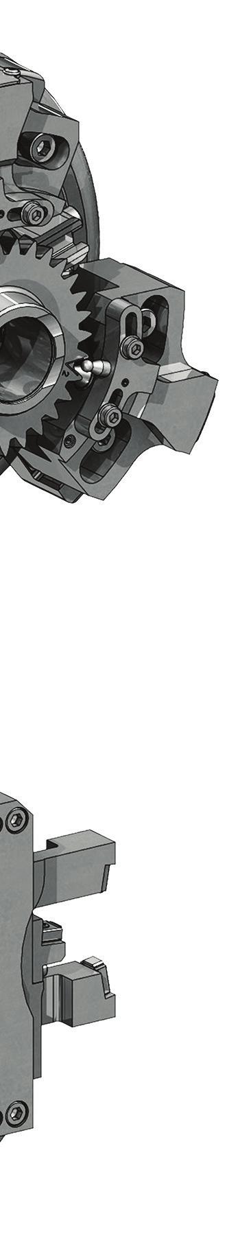
20 Type D-VARIO Diaphragm chuck FLEXIBLE MODULAR SYSTEM Main dimensions and technical data Application/customer benefits Flexible solution for grinding with quick adjustment for short set up times Technical features Adjustable, modular jaw system for clamping different work pieces with the same jaws Key Lock System for quick positioning of the pitch of different work pieces Micrometer fine adjustment of the center line For small, medium and large batch sizes Workstop with medium feed for air sensing and integrated coolant nozzles optional Jaws for O.D. clamping (Type A) optional D-Vario Configurator: free application to configurate your set up ( Standard equipment Diaphragm chuck D-Vario (with mounting bolts) Optional accessories in the modular system: Pitch line clamping 6 different jaw sets for different outside diameters Key Lock System for different pitches of gears (see figure A, B and C) Clamping pins for different modules (Dia. of ball Ø 3,0 mm to 6,0 mm) Locators O.D. clamping (Type A) 4 different jaw blanks for different outside diameters Factory finished jaws Locators With these free of charge D-VARIO Configurator you will be able to create individual configurations for different gears and set-ups. For input the data, there are only 3 steps needed. Optional you could also make the interpretation of the work stop and the associated support bolts. Through the integrated export function, the results can be saved at any time or transfered to a printer. Start Web-App: Safe and quick configuration of all set-ups for different gears Web-APP: from anywhere with any device feasible (internet access needed) Availability for exporting all resolution of the results A: Number of teeth is divisible by 3 Example of application: gear with number of teeth [z] = 30 B: Number of teeth is not divisible by 3 Example of application: gear with number of teeth [z] = 31 C: Number of teeth is not divisible by 3 Example of application: gear with number of teeth [z] = , , ,75 123, , , Specification of Key Lock System: 3x Key straight Specification of Key Lock System: 1x Key straight, 2x Key for number of teeth 31 Specification of Key Lock System: 1x Key straight, 2x Key for number of teeth 32

21 Type D-VARIO Main dimensions and technical data Diaphragm chuck FLEXIBLE MODULAR SYSTEM Top jaws and locator base are optional. Subject to technical changes For more detailed information please ask for customer drawing. SMW-AUTOBLOK Type Mounting Id. No. Locating Face for Locator Clamping range min./max. Swing min. Swing max. Jaw height Piston stroke Jaw stroke at distance H Draw pull min./max.* Draw pull for chuck open Moment of inertia Weight without top tooling D-VARIO 215 Z A mm 215 B mm 49.5 C mm 68.5 D mm D1 mm 215 D2 mm 264 E mm 170 F mm G G1 M12 M24x1.5 H mm 40.5 J mm 6 P H8 mm 25 Q mm 7 R mm 20 S mm 1.0 mm 0.95 kn 0-15 kn 15 kg m kg 12.2 Recommended actuating cylinders Type SIN-DFR * Additional draw pull to the diaphragme force actuated by the actuating cylinder Advice: Please note: It is important, that the cylinder force for pushing and pulling can be set to different values independently!


.")


22 Type D-VARIO Diaphragm chuck FLEXIBLE MODULAR SYSTEM Overview clamping kit Configuration of the set up for pitch line clamping within only 5 steps: I II III IV V First you have to choose your matching top jaw (size 1-6) for the outside diameter [d a ] of the gear to be machined. Each size of top jaw can cover 20 mm outside diameter using two different types of clamping pins (Type A and B). One set of top jaw consists of 3 pieces including 1 straight Key Lock insert. The determination of the spherical clamping pins is made according to the ball dimension of the gear. There are 2 types of clamping pins: Type A for the first 10 mm of the clamping range of the top jaws. Type B for the second 10 mm of the clamping range of the top jaws. Optionally prelocator pins are available. Prelocator pins are used at automatic loading. The determination is made according to the clamping pins used. One set of Key Lock insert consists of 2 keys. Gears, which number of teeth that is divisible by 3 can be machined with 3 of the same type Key Lock insert (straight). For all gears, which number of teeth is not divisible by 3, there are different key insert sets available according to the number of teeth. The Key Lock inserts are the same for all 6 sizes of top jaws. The following types of locator bases are available: Type A: without air sensing / without nozzle for coolant Type B: without air sensing/with nozzle for coolant Type C: with air sensing / with nozzle for coolant The height of the locator posts is depending on the gear. Overview of the clamping kit: Top jaws (1 set = 3 pcs.) available in 6 sizes for different outside diameters [d a ] 1 pcs. key insert straight contained in the set of the top jaws Gear Parameter for the configuration of the clamping kit: Outside diameter [d a ] Clamping pin (1 set = 3 pcs.) Ball diameter 3-6mm for different ball dimensions Gear Gear Key Lock inserts (1 set = 2 pcs.) for different numer of teeth [z] Number of teeth [z] Ball dimension D-Vario Configurator free application to configurate your set up


 Clamping pin type Set Type A Available prelocator pins Ball diameter Ø 3,0 Ball diameter Ø 3,5 Ball diameter Ø 4,0 Ball diameter Ø")

23 Configuration of the clamping kit I. Determination of the top jaws Top Jaws Size Type D-VARIO Diaphragm chuck FLEXIBLE MODULAR SYSTEM Outside diameter of gear d a mm Number of teeth z number Inside clearance diameter of jaws mm Swing diameter mm Weight / set kg Order number / set of 3 pieces Id. No Clamping pin Type Clamping range A B A B A B A B A B A B mm II. / III. Determination of the clamping pins (and optional prelocator pins) Clamping pin type Set Type A Available prelocator pins Ball diameter Ø 3,0 Ball diameter Ø 3,5 Ball diameter Ø 4,0 Ball diameter Ø 4,5 Ball diameter Ø 5,0 Ball diameter Ø 5,5 Ball diameter Ø 6,0 Id. No. Id. No. Id. No. Id. No. Id. No. Id. No. Id. No. Type B Available prelocator pins Clamping pins Clamping pin type A [ Top jaw 1 Top jaw 2 Top jaw 3 Top jaw 4 Ø mm Ø mm Ø mm Ø mm Clamping pin type A For the first 10 mm of the clamping range of the top jaws. Ball diameter Ø 3; 3,5; 4; 4,5; 5; 5,5; 6 Clamping pin type B Top jaw 5 Top jaw 6 Top jaw 1 Ø mm Ø mm Ø mm Clamping pin type B For the second 10 mm of the clamping range of the top jaws. Ball diameter Ø 3; 3,5; 4; 4,5; 5; 5,5; 6 [ Top jaw 2 Top jaw 3 Top jaw 4 Top jaw 5 Top jaw 6 Ø mm Ø mm Ø mm Ø mm Ø mm Compatibility All types and sizes of clamping bolts are compatible to all top jaws.


24 Type D-VARIO Diaphragm chuck FLEXIBLE MODULAR SYSTEM Configuration of the clamping kit IV. Key Lock inserts for different number of teeth of gears Id. No. Key Lock insert for gears which number of teeths is not divisible by 3 (1 set = 2 pcs.) z = 10 z = 11 z = 13 z = 14 z = 16 z = 17 z = 19 z = 20 z = 22 z = z = 25 z = 26 z = 28 z = 29 z = 31 z = 32 z = 34 z = 35 z = 37 z = z = 40 z = 41 z = 43 z = 44 z = 46 z = 47 z = 49 z = 50 z = 52 z = z = 55 z = 56 z = 58 z = 59 z = 61 z = 62 z = 64 z = 65 z = 67 z = z = 70 z = 71 z = 73 z = 74 z = 76 z = 77 z = 79 z = 80 z = 82 z = z = 85 z = Id. No. Key Lock insert for gears which number of teeths is divisible by 3 (1 set = 2 pcs.) straight Order Example: Gear with number of teeth 32 not divisible by 3 Id. No (1 set = 2 pcs.) Gear with number of teeth 33 divisible by 3 Id. No (1 set = 2 pcs.) 1 straight Key Look that comes with the chuck always remains in use. Key Lock insert (1 set = 2 pcs.) [ Top jaw 1 Top jaw 2 Top jaw 3 Top jaw 4 Compatibility All Key Lock inserts are compatible to all top jaws. Top jaw 5 Top jaw 6

![position and locating face Height of locator posts [H] = 32,5 mm - Clamping position = 1/2 serration length / at longer serrations it is the requested clamping position.](/docs-images/81/84372012/images/25-3.jpg "In case the lowest face is not the locating face, please ask our customer service. Locator base Type A Type B Type C Medium feed for air sensing - - X Noozle for coolant - X X Locating diameter min.")
25 Type D-VARIO Configuration of the clamping kit V. Locator base Diaphragm chuck FLEXIBLE MODULAR SYSTEM Locator base Clamping pin Top jaw Workpiece Locator post Ø 10mm Locator base Determination of height of locator posts: = Distance between clamping position and locating face Height of locator posts [H] = 32,5 mm - Clamping position = 1/2 serration length / at longer serrations it is the requested clamping position. In case the lowest face is not the locating face, please ask our customer service. Locator base Type A Type B Type C Medium feed for air sensing - - X Noozle for coolant - X X Locating diameter min. D min Locating diameter max. D1 max Width B mm Order Number Id. No Locator posts with contact face diameter [E] 2,5 mm Height[H] = 12,5 mm Height[H] = 15,0 mm Height[H] = 17,5 mm Height[H] = 20,0 mm Height[H] = 22,5 mm Height[H] = 25,0 mm Height[H] = 27,5 mm Height[H] = 30,0 mm Height[H] = 32,5 mm Height[H] = 35,0 mm Height[H] = 37,5 mm Height[H] = 40,0 mm Height[H] = 42,5 mm Height[H] = 45,0 mm Height[H] = 47,5 mm Height[H] = 50,0 mm I.D. Number is for one set (=3 pieces) Locator posts with contact face diameter [E] 4,5 mm Height[H] = 12,5 mm Height[H] = 15,0 mm Height[H] = 17,5 mm Height[H] = 20,0 mm Height[H] = 22,5 mm Height[H] = 25,0 mm Height[H] = 27,5 mm Height[H] = 30,0 mm Height[H] = 32,5 mm Height[H] = 35,0 mm Height[H] = 37,5 mm Height[H] = 40,0 mm Height[H] = 42,5 mm Height[H] = 45,0 mm Height[H] = 47,5 mm Height[H] = 50,0 mm I.D. Number is for one set (=3 pieces)
 Jaws factory finished* (set of 3 pcs.) 1 2 3 4 5 6 mm 20-40 40-60 60-80 80-100 100-120 120-140 kg 1,1 1,1 1,0 1,0 1,0 0,8 Id. No.")


26 Type D-VARIO Diaphragm chuck FLEXIBLE MODULAR SYSTEM Jaws Type A Jaws type A for O.D. clamping Jaws Type A (through hardened) D max. Clamping diameter range D min. Jaws type A Clamping Range Ø D min. - D max. Weight / set Blank jaws (set of 3 pcs.) Jaws factory finished* (set of 3 pcs.) mm kg 1,1 1,1 1,0 1,0 1,0 0,8 Id. No Id. No * Jaws are factory finished according to the specified clamping diameter. Note: The clamping diameter must be specified in case of order. Device Grinding rings (1 Set = 2 pcs.) Device for machining of the blank jaws type A Recommended grinding rings Jaws type A sizes Jaws type A sizes The device is needed to pre-machine the blank jaws type A. Then, the jaws must be finish ground to the clamping diameter on the D-Vario chuck. For this operation, the jaws have to be clamped with the grinding rings. Grinding data 1. Grinding A1 D = 177,0 mm residual jaw stroke 0,25 mm 2. Grinding A2 D = 176,9 mm residual jaw stroke 0,20 mm 3. Grinding A3 D = 176,8 mm residual jaw stroke 0,15 mm 4. Grinding A4 D = 176,7 mm residual jaw stroke 0,10 mm The clamping diameter A1 is used for the first finish grinding process. The smaller clamping diameter of the grinding rings (A2-A4) are used to regrind worn or damaged existing jaws.


27 FDG Chapter 4 FDG High precision face drivers for machining between center pins Machining of the entire surface of the workpiece with one single operation Power operated on the side of the spindle Highest rund-out accuracy


28 Face drivers for grinding between center pins Power operated on the side of the spindle FDG Application/customer benefits Machining of the entire surface of the workpiece in one single operation For the machining of the surface of soft and hardened workpieces Center pin with carbide insert for highest running accuracy Technische features Highest run-out accuracy < mm Compensating drive elements Retractable drive pins in case of on- or off-loading Fine adjustment at face drivers for highest run-out requirements Standard equipment Accessories Face driver FDG Pneumatic pancake cylinder CPG-FDG without changeable parts Id.No A Cylindrical retainer Z140 on flange adapter total stroke 6 Ø165 Ø Ø160 Ø133,4 3x for x M12 Ø106,375 (KK Gr.6) d5 Ø6 d8 D1 D2 D3 d7 d9 d Short taper retainer DIN size 6 directly onto machine spindle A 92 Subject to technical changes. For more detailed information please ask for customer drawing. Technical Data Id.-No. Id.-No. Type d Center d5 d7 d8 d9 Clamping dia Ø Z140 KK size 6 Ø D1 D2 D FDG , FDG FDG , , FDG , , FDG , FDG , FDG , Face drivers with morse taper retainer according to DIN 228 available on request. NOTE Pancake cylinder CPG for the pneumatic actuation of face drivers FDG available.


29 d8 d1 60 d1 d7 60 I I I FDG Face drivers for grinding between center pins Changeable parts Center heads / Center pins Application/customer benefits Center pin with carbide insert Maximum rigidity Highest change accuracy Fixed safely via set screw and plane surface inside the face driver Center heads Type FDG 0 and FDG 1 60 center with carbide coating. Center pins Type FDG 2 to FDG 6 carbide design. A 28 Center heads Type FDG 0 / FDG 1 Center pins Type FDG 2 - FDG 6 Ø6 A d8 d4 d9 Id.-No. Type d1 d4 Center d7 d8 d9 Center pin Ø FDG FDG FDG FDG FDG FDG FDG Further dimensions on request. Drive pins with diamond coating Model A Ø6 Ø6 Ø6 Model B Model C Drive pins diamond Id.-No. Type Clamping I Model drive pin diameter diamond D1 1.5 C diamond D2 3 B diamond D3 3 A Further dimensions on request. Drive pins for torque transmission onto the workpiece Drive pins with diamond coating High frictional coefficient Clamping diameter D1/D2/D3 see page 1.


30 CPG Chapter 5 CPG Pneumatic pancake cylinder for diaphragm chuck D-VARIO and face driver FDG Easy installation for grinding and turning machines without hydraulic unit Operating pressure 2-8 bar Medieum feed for air / coolant


 Version FDG Id.No. 045891 APFL3 Id.")

 Axial force at 6 bar (push) Moment of")
 Piston area (piston push) Operating pressure Weight CPG 215 A mm 215 B mm 170 C mm 195")
31 A С D E G F K B P J Pneumatic pancake cylinder D-VARIO / FDG Pneumatic actuation (2-8 bar) Easy installation for grinding and turning machines Application/customer benefits For the actuation of diaphragm chuck D-VARIO and face driver FDG Easy installation for grinding and turning machines without hydraulic unit Compact design Technical features Operating pressure 2-8 bar Maximum axial piston force push 21 kn and pull 7 kn 1 medium feed for air / coolant Air service unit with water separator and oil feed necessary Air feed tube necessary Standard equipment Odering example Pneumatic pancake cylinder Version D-VARIO Id.No (without air feed tube) Version FDG Id.No APFL3 Id.No CPG H M W N Accessory Q S O R APFL3 Air feed tube 3 Connections: 1x Actuation "push" 1x Actuation "pull" 1x Additional medium channel for air/coolant U Subject to technical changes. For more detailed information please ask for customer drawing. A Id. No Technical Data SMW-AUTOBLOK Type Piston stroke Axial force 6 bar (pull) Axial force at 6 bar (push) Moment of inertia Max. speed Piston area (piston pull) Piston area (piston push) Operating pressure Weight CPG 215 A mm 215 B mm 170 C mm 195 D mm E mm 30 F mm M25x1.5 G mm 16 H mm 54.5 J mm 116 K mm L mm 2 M mm 46.3 N mm 6.2 O mm 3 P mm 3x M12x120 Q mm M6 R mm M14 S mm 16 U mm 4 kn 5 kn 16 kg m² 0.09 U/min cm² 291 cm² 98 bar 2-8 kg 11.1


32 EMS Chapter 6 EMS Segment sleeve mandrels Clamping diameter Ø mm For ID clamping Rigid design
 with bayonet quick change.")


33 I EM-S Segment sleeve mandrel Ø mm Segment sleeve mandrel power operated Technical design Size 1-4 Large expansibility 1. Basic body EM-S with spindle adapter 2. Segment sleeve mandrel (vulcanized + case hardened) with bayonet quick change. Clamping sleeves in size EM-S-1 with three segments, clamping sleeves from size EM-S-2 on with six segments for better gripping force distribution. 3. Workstop Overview clamping ranges EM-S-4 Clamping range mm EM-S-3 Clamping range mm EM-S-2 Clamping range mm EM-S-1 Clamping range mm Clamping sleeves EM-S-1* Ø 18 Id. No Ø 31 Id. No EM-S-2** Ø 30 Id. No Ø 43 Id. No EM-S-3** Ø Id. No Ø 58 Id. No Ø 71 Id. No EM-S-4** Type EM-S-1 EM-S-2 EM-S-3 EM-S-4 Id. No A C D E F H I K M N O M5 M5 M5 M EM-S Ø Id. No Ø Id. No Ø Id. No * The clamping sleeves have a max. radial expansibility in diameter of ± 0.4 mm from the nominal diameter. ** The clamping sleeves have a max. radial expansibility in diameter of ± 0.6 mm from the nominal diameter. Soft work stop blank EM-S-2 / EM-S-3 / EM-S A D N O H F C E M K


34 Segment sleeve mandrel Ø mm Size 1-4 Large expansibility EM-S Segment sleeve mandrel power operated Application/ customer benefit Ideal for volume production and hard turning / grinding with wear resistant, case hardened and vulcanised clamping sleeves Highest accuracy and high torque transmission by means of fixed mandrel body Axial pull down by the axial clamping movement of the clamping sleeve = best face run out Clamping sleeve quick change for short setup times Preparation for air sensing Technical details Large expansibilty mm depending on the size (The clamping sleeves have a max. radial expansibility in diameter of ± 0.4 mm or ± 0.6 mm from the nominal diameter.) Power operated Rigid design with flange mounting Tapped holes in the face for axial stops Standard equipment Bayonet quick change Base mandrel with mounting bolts L4 L6 L9 L3 L2 L1 air sensing S2 S3 K D7 S1 D3 D2 D1 A2 D6 A1 D5 D4 L5 L7 L8 L5 Attention: Sleeve mandrel in open position = right end position! Gap "L8" must remain open when using airsensing! Subject to technical changes. For more detailed information please ask for customer drawing. L6 L4 L3 L9 L2 L1 SMW-AUTOBLOK Type EM-S-1 EM-S-2 EM-S-3 EM-S-4 Mounting A5 A6 Z140 A5 A6 Z140 A5 A6 A08 Z140 Z170 A5 A6 A8 Z140 Z170 Id. No Short taper mounting DIN A1 A5 A6 - A5 A6 - A5 A6 A8 - - A5 A6 A8 - - Center mounting A2 H D D D D4 M30x1.5 M30x1.5 M30x1.5 M30x1.5 M30x1.5 M30x1.5 M30x1.5 M30x1.5 M30x1.5 M30x1.5 M30x1.5 M30x1.5 M30x1.5 M30x1.5 M30x1.5 M30x1.5 D5 H D D7 4 x M10 4 x M12 4 x M10 4 x M10 4 x M12 4 x M10 4 x M10 4 x M12 4 x M16 4 x M10 4 x M12 4 x M10 4 x M12 4 x M16 4 x M10 4 x M12 L L L L L L L Gap L L Technical data Clamping range S max. clamping length S min. clamping length S Axial stroke K Expansibilty in dia max. actuating force kn max. speed min max. transmittable torque Nm rec. actuating cylinders SIN-S 70 SIN-S 85 SIN-S 85 SIN-S 85
Jaw chuck B-Top3 STANDARD CHUCKS. 215 Variant. Jaw chuck B-Top3. Technical data. Size. B-Top3
 STANDARD CHUCKS. Technical data A AJ DH AI AT AW T BQ AS Size 215 ariant B-Top3 Concentricity [mm] Max. clamping force [kn] Max. axial drawtube force [kn] RPM n max. [1/min.] Stroke per jaw [mm] Ø Capacity
5-Axis Machine Tools from SMW-AUTOBLOK
 5-Axis Machine Tools from SMW-AUTOBLOK 5-Axis Machine Tools ensures the following advantages: Ideal suitable for OP 10 use ST5-2G also suitable for OP 20 use Jaws with SinterGrip clamping inserts for clamping
5-Axis Machine Tools from SMW-AUTOBLOK
 -Axis Machine Tools from SMW-AUTOBLOK -Axis Machine Tools ensures the following advantages: Ideal suitable for OP 10 use Jaws with SinterGrip clamping inserts for clamping of workpieces with lowest depth
Precision Chucks for Improved Accuracy and Increased Productivity
 Precision Workholding Technology Precision Chucks for Improved Accuracy and Increased Productivity Precision Air Chucks (Self Contained Design) MicroCentric Precision Air Chucks feature a patented open
PATENT EP COMPENSATING CHUCKS OVEKA & KA
 PATENT EP1 190 815 COMPENSATING CHUCKS OVEKA & KA COMPENSATING CHUCKS For centric cylindrical, orbital pin or form grinding of complex shaft-type components, the workpiece is generally ground between centers.
OIL AND GAS. Clamping technology for crude oil and natural gas industries
 OIL AND GAS Clamping technology for crude oil and natural gas industries CRUDE OIL AND NATURAL GAS - THE ENERGY OF TODAY RÖHM is the specialist for clamping technology with a wide product range, unrivaled
Example workpieces: - Gearbox casing. Example format: - Diameter 800 mm
 RADIAL CHUCKS SAV 260.99-RSF 3 + 3 JAW CHUCKS - 3 + 3 jaw chuck with two independently actuated clamping circles - Easily adaptable from centred to balanced operation - Jaw stroke 15 mm (Stroke per jaw)
High Precision Air Chucks
 Precision Workholding Solutions High Precision Air Chucks www..com Improve productivity and lower the cost of secondary machining operations..... through high concentricity. Holding close concentricity
High Precision Diaphragm Chucks
 Precision Workholding Technology High Precision Diaphragm Chucks Unique Diaphragm Chuck Design MicroCentric Improving the quality and efficiency of secondary machining operations.... through high workpiece
PATENT EP Compensating Chuck Retractable OVEKAV / OVARZV
 PATENT EP1 190 815 Compensating Chuck Retractable OVEKAV / OVARZV COMPENSATING CHUCK - RETRACTABLE The OVEKAV / OVARZV retractable compensating chucks made by SwissChuck are unique! These chucking systems
 .. 8. 2. 9. 22. 0.. 2.. 2. 2.... 28. 29.... 8. 9. PBL Universal Ball-Lock Power Castings or forgings can be.d. or I.D. clamped Grips on taper up to 0 Jaws pivot up to to grip on uneven surfaces Ideal for
CLAMPING TECHNOLOGY SPECIAL SOLUTIONS
 CLAMPING TECHNOLOGY SPECIAL SOLUTIONS BESPOKE SPECIAL SOLUTIONS You define the task and we develop and implement the solution! Special clamping chucks are tailor-made products. They are adapted to your
e-cylinder Saves energy and cash ENERGY EFFICIENCY
 e-cylinder Saves energy and cash ENERGY EFFICIENCY Calculation example for energy and time saving ENERGY EFFICIENCY Sample calculation for energy savings with an electrical cylinder: Energy consumption
CLAMPING TECHNOLOGY Individual special clamping tools
 CLAMPING TECHNOLOGY Individual special clamping tools 1 QUALITY SINCE 1958 Know-how, the highest quality and first class engineering. We see ourselves as a system supplier and offer our customers a full
Efficient workholding. Collet Chucks Mandrels Collets
 TM Efficient workholding ollet hucks Mandrels ollets Index ollet huck Index of Klamp Products ollet hucks Q & Series Page 3 Quick hange ollet hucks QRL Series Page 4-7 Short Series ollet hucks RS Series
Air precision chucks APC
 Air precision chucks APC MicroCentric GmbH Berblingerstr. 16 71254 Ditzingen / Germany Tel.: +49 (0)7156 17819-0 Fax: +49 (0)7156 17819-20 E-Mail: info@microcentric.de www.microcentric.de Products in this
TOOL CLAMPING SYSTEMS
 TOOL CLAMPING SYSTEMS 2017 NEW RÖHM eshop First B2B eshop of the clamping technology industry Buy RÖHM products online 24/7 Order as a guest customer without registration Intuitive search and filter function
Zero Point Clamping System. ZERO lock BALL lock
 Zero Point Clamping System ZERO lock BALL lock kap3 kap 263 Technical information regarding ZERO lock Zero Point Clamping System Application The modularly designed, flexible ZERO lock Zero-Point Clamping
BIG BORE 2G chucks BB-N-EXL2G BB-AZ2G BB-FZA2G BB-EXL-SC2G
 Clamping of pipe with IG ORE 2G chucks -Z2G -FZ2G -EXL-C2G IG ORE elf centering Extra long jaw stroke Jaw jogging IG ORE -Z2G elf centering or compensating Extra long jaw stroke afety features: : Pressure
TAPPING CHUCKS & COLLETS
 TAPPING CHUCKS & COLLETS CAT er Tension/Compression Holders 86 CAT er Rigid Holders 86 BT er Tension/Compression Holders 87 BT er Rigid Holders 87 HSK Tension/Compression & Rigid Holders 88 NMTB er Tension/Compression
WORKHOLDING MADE IN EUROPE MANUAL LATHE CHUCKS, CENTERS, ROTATING BODIES OIL COUNTRY CHUCKS, POWER CHUCKS, VTL CHUCKS, ROTARY TABLE PACKAGES
 EUROPEAN PRECISION & QUALITY WORKHOLDING MADE IN EUROPE MANUAL LATHE CHUCKS, CENTERS, ROTATING BODIES OIL COUNTRY CHUCKS, POWER CHUCKS, VTL CHUCKS, ROTARY TABLE PACKAGES EUROPEAN PRECISION & QUALITY With
WM en. Zero point clamping system SPEEDY airtec 1
 SPEEDY airtec 1 GO! Maximum productivity Using the zero point clamping system SPEEDY classic you will increase your productivity to a maximum. Adjustment and checking processes are no longer necessary
Technical features. Positive Taper Lock System for manual tool clamping. Technical features:
 clamping set Technical features The RÖHM- was specially designed for the positive taper lock clamping taking particulary into account the necessity of manual clamping. Technical features: strong design
5-axis clamping system compact
 5-axis clamping system compact 395 5-axis clamping system compact Function We are setting standards with the new KIPP 5-axis clamping system compact in this field. The system was specifically designed
Clamping devices 521
 Clamping devices 521 522 Product overview Clamping devices Adjustable straps K0001 Hook clamps K0012 Goose-neck straps with long slot K0002 Page 526 Hook Clamps with collar K0013 Page 535 Equipped clamps
Compatibility overview of accessories for lathe
 Compatibility overview of accessories for lathe Accessory parts for turning Face clamping disc Ø 170 mm 3440295 Face clamping disc Ø 240 mm 3441352 Face clamping disc Ø 250 mm 3440552 Face clamping disc
Dimensions of the machine spindle heads in accordance with DIN The latest issue of the DIN sheet is binding
 Info Dimensions of the machine spindle heads in accordance with DIN The latest issue of the DIN sheet is binding DIN 55026 from taper size 4 with driver. Spindle head Size C1 C2 D hole count outer olt
. Dimensions of the Machine Spindle Heads in Compliance with DIN The most recent editions of the DIN standards are binding.
 Clamping technology. Dimensions of the Machine Spindle Heads in Compliance with DIN The most recent editions of the DIN standards are binding. DIN 55026 Taper sizes 4 and above with drive tang. Spindle
ACCESSORIES CATALOG BORING AND FACING HEADS LIVE CENTERS
 ACCESSORIES CATALOG BORING AND FACING HEADS LIVE CENTERS SKODA LIVE CENTERS SKODA & STM HEAVY DUTY LIVE CENTERS - CSN 243324 Features The rotating spindle is extended right through the tapered shank Two
NEW HIGH-PRECISION TOOL GRIND CHUCK TGC P O
 NEW HIGH-PRECISION TOOL GRIND CHUCK TGC P O HIGH-PRECISION TOOL GRIND CHUCK TGC P O Increase your productivity and lower your costs! Whenever high-performance tools are manufactured, there is a need for
Clamping bolts Eccentrical cams clamping units
 2.3 Shaft Clamping bolts Eccentrical cams clamping units 2.9 2.8 2.7 2.6 2.5 2.4 2.3 2.2 2.1 2.3 Clamping bolts, Eccentrical cams, Shaft clamping units Page 641 2.3 Clamping bolts, Eccentrical cams, Shaft
1.3. Face Drivers for Grinding. FFBR with Flange Retainer. FBSR with Taper Shank Retainer. FFBR/FBSR Changeable Parts FFB/FFBH.
 1.3 Face Drivers for Grinding FFBR with Flange Retainer FBSR with Taper Shank Retainer FFBR/FBSR Changeable Parts FFB/FFBH FFB/FFBH Changeable Parts FBSR PN/FFPR/FBS Special Face Drivers NEIDLEIN-SPANNZEUGE
Troubleshooting for Milling Chuck. Details of the trouble Cause Solution / Countermeasures
 TROUBLESHOOTING 571 Troubleshooting Troubleshooting for Milling Chuck Details of the trouble Cause Solution / Countermeasures Tool cannot be held Tool shank diameter should be within h7 tolerance. Tool
WM en. Zero point clamping system system 3000
 Zero point clamping system system 3000 unique push-on very strong automatic monitoring flush mounted SPEEDY and spigot handling without interfering contour 50kN retention force suitable for automation
Face Drivers with appropriate changable parts and accessories
 8 NEIDLEIN-SPANNZEUGE GmbH www.neidlein.de 9 Face Drivers with appropriate changable parts and accessories FSB FFB FSP FFBR FDNC FOR TURNING AND HARD TURNING WITH DRIVE PINS Face Drivers FSB / SB 10 Face
Hydraulic Clamping Systems
 Hydraulic Clamping Systems Hydraulic Swivel clamps, double action Operating pressure max. 250 bar Hydraulic swivel clamps are particularly designed for applications which require high clamping forces and
Complete O.D. Machining in One Operation
 MFDODM209 Complete O.D. Machining in One Operation Including: Hydra-Drive For Extreme Accuracy CREATING INNOVATIONS IN FACE DRIVING TECHNOLOGY www.facedrivers.com Complete O.D. Machining in one Operation
Industrial Drill Chucks with Key. For Stationary Machines and Portable Drilling Machines. Diameter (mm)
") Drilling Industrial Drill Chucks with Key For Stationary Machines and Portable Drilling Machines Specifically designed for stationary drilling, turning, milling and wood working machines The one-piece
Drilling Industrial Drill Chucks with Key For Stationary Machines and Portable Drilling Machines Specifically designed for stationary drilling, turning, milling and wood working machines The one-piece
Chuck adapters Top jaws T-nuts Grippers Gripping force meter Grease Accessories
 Chuck adapters Top jaws T-nuts Grippers Gripping force meter Grease Accessories Chuck adapters DIN 55026/ISO-A 702/1 Mounting adapters on short taper spindle noses direct and indirect mounting reduction
Product Information. Deburring spindle FDB-AC
 Product Information FDB-AC FDB-AC Compliant. Reliable. Flexible. FDB-AC deburring spindle Flexible deburring spindle for use in robotic applications Field of application Standard solution for flexible
Screwdriver Function Module for the automatic Screw-Assembly
 Screwdriving Technology Automation Air Motors Air Tools Screwdriver Function Module for the automatic Screw-Assembly n wide product variety for all applications n maximum ease of integration n service
Pull-down clamps. No Low height clamping jaws, model Bulle
 Pull-down clamps The wedge action of clamping jaws is the characteristic feature of these pull down clamps. It causes the pull down effect, which presses the workpiece against both, stop and machine table.
LIVE CENTRES FACE DRIVERS
 LIVE CENTRES FACE DRIVERS 2017 NEW RÖHM eshop First B2B eshop of the clamping technology industry Buy RÖHM products online 24/7 Order as a guest customer without registration Intuitive search and filter
Hardinge FlexC Dead-Length Collet System Style DL 42mm. Installation Instructions and Parts Lists
 Hardinge FlexC Dead-Length Collet System Style DL 42mm Installation Instructions and Parts Lists 1 General Safety Information Before installing the Hardinge FlexC Collet System on your machine tool, thoroughly
LIVE CENTRES FACE DRIVERS
 LIVE CENTRES FACE DRIVERS 2015/2016 We work for customers who have a weakness for our strengths. Companies intent on making a difference are obliged to develop constantly as well as deploy their strengths
Operating instruction for the quick-change tap holders type:
 type: KSN 0 KSN 1 KSN 3 KSN 4 KSN 5 Date of edition: 01.02.2008 Stage of alteration: 1 Please keep this for future use! Contents: 1 Application range, safety instructions and technical data... 3 1.1 Application
ACCESSORIES CATALOG. SKODA LIVE CENTERS BORING AND FACING HEADS
 ACCESSORIES CATALOG BORING AND FACING HEADS SKODA LIVE CENTERS www.sowatool.com SKODA LIVE CENTERS Skoda Heavy Duty Live Centers - CSN 4334/CSN 4334M Features The rotating spindle is extended right through
. Dimensions of Machine Spindle Heads in Compliance with DIN The most recent editions of the DIN standards are binding
 ß Clamping tools. Dimensions of Machine Spindle Heads in Compliance with DIN The most recent editions of the DIN standards are binding DIN 5506 Taper sizes 4 and above with driver. Spindle No. of holes
SUMMARY. V-Lock SYSTEM BASIC ELEMENTS ACTUATORS. P V-Lock GENERAL INTRODUCTION 2. P V-Lock FIXING ELEMENTS 10 SUMMARY. P V-Lock ADAPTORS 17
 SUMMARY A3 V-Lock SYSTEM P V-Lock GENERAL INTRODUCTION 2 BASIC ELEMENTS P V-Lock FIXING ELEMENTS 10 P V-Lock ADAPTORS 17 SUMMARY P PROFILES 28 P V-Lock ACCESSORIES AND SPARE PARTS 32 1 A3 GENERAL INTRODUCTION
MACHINE TOOL ACCESSORIES
 VERTICAL 5-C COLLET VISE SERIES 344: VERTICAL 3-C COLLET VISE SERIES 344: : 2-1/2 x 7-3/4 Height: 4 Small movement of lever opens or closes collet. 2030000 CAM OPERATED 5-C HORIZONTAL/VERTICAL COLLET FIXTURE
LOW-PROFILE ACCU-LENGTH CNC COLLET CHUCKS
 LOW-PROFILE ACCU-LENGTH CNC COLLET CHUCKS High RPM All Royal CNC collet chucks are balanced by design for high-speed operation, and can often be run at higher speeds than conventional 3-jaw chucks because
Face Drivers FSP / FSPB
 4 Face Drivers FSP / FSPB NEIDLEIN-SPANNZEUGE GmbH Face Drivers FSP / FSPB with drive disk and movable center pin The entire surface of the workpiece can be tooled and finished by clamping with a maximum
NEIDLEIN LIVE CENTERS AND DEAD CENTERS
 NEIDEIN IVE CENTERS AND DEAD CENTERS Ultra ive Center RN Type RN with morse taper NEIDEIN ultra live centers are designed for employment in turning, grinding and other production machines. Owing to the
CM6200 MILLING MACHINE
 CM6200 MILLING MACHINE PORTABLE ON - SITE MACHINING SOLUTIONS FOR LARGE FLANGE MACHINING Quality Machine Design Provides Rigid, Power-Packed Performance Extraordinarily rigid design ensures consistent,
New Product Listing. Pages SET-TRU CHUCKS 2 Jaw with Soft Top jaws, 3 & 6 Jaw with Solid OD & ID Jaws, 4 Jaw with Two-piece Reversible
 NUMERICAL INDEX PARTIAL CODE NO. PAGE NO. PARTIAL CODE NO. PAGE NO. PARTIAL CODE NO. PAGE NO. 714... 9 718... 9 7202... 102 7203... 102 7205... 104 720... 107 7207... 104 7208... 104 7209... 107 7210...
Compatibility overview of accessories for lathe
 Compatibility overview of accessories for lathe Accessory parts for turning TU 1503 TU 2004 TU 2304 TU 2404 TU 2506 TU 2807 D 320 TU 3209 D 330 D 360 TU 3610V TZ 4012 D 420 TU 4210V D 460 TU 4615V TZ 5216
5-AXIS MACHINING SCS QUINTUS WWW. WORKHOLDINGSOLUTIONSGROUP. COM
 WORKHOLDING SOLUTIONS FOR -AXIS MACHINING SCS MC QUINTUS ONE system / MANY solutions WWW. WORKHOLDINGSOLUTIONSGROUP. COM MCCLAMPING S YSTEM for -axis machining MC + Quintus... MC Clamping System Free access
KTM-16/20 TECHNICAL DATA
 TECHNICAL DATA Table Diameter : 1,600mm Max. Turning Diameter : 2,000mm Max. Turning Height : 1,750mm Table Indexing Degree : 0.001mm CNC Controller : FANUC 18i-TB ** Bed The bed has symmetrical structure
» Modular clamping elements for optical or optical/tactical measurement» For high-precision edge measurements in reflected and transmitted light
 » Modular clamping elements for optical or optical/tactical measurement» For highprecision edge measurements in reflected and transmitted light» Toothed rails as workpiece stops or for fastening clamping
PPC Series Precision Power Chucks
 Precision Workholding Technology PPC Series Precision Power Chucks www.microcentric.com The World s Most Accurate Power Chuck Improve productivity and lower costs by enhancing workpiece quality...... through
CNC EXPANDING MANDRELS
 CNC EXPANDING MANDRELS ID CLAMPING OFFERS FULL OD PART ACCESS PARALLEL EXPANSION FOR OPTIMUM ACCURACY AND GRIP FORCE LARGE RANGE IN STOCK FOR IMMEDIATE SHIPMENT ROYAL CNC EXPANDING MANDRELS Rigid and Accurate
Hardinge FlexC Collet System Style D 65mm
 Hardinge FlexC Collet System Style D 65mm Installation Instructions and Parts Lists 1 General Safety Information Before installing the Hardinge FlexC Collet System on your machine tool, thoroughly read
.com More than a machine. Power your life. Precise Centre Metal Lathes. Advanced Technology, Complete
 Precise Centre Metal Lathes. Advanced Technology, Complete Equipment, Easy-to-Operate. This kind of MM-D420X1000 universal metal lathe machine is a fantastic model for small to medium-size turning works
QUICK-GRIP CNC COLLET CHUCKS
 QUICK-GRIP CNC COLLET CHUCKS TEN-SECOND COLLET CHANGES 0.0002" TIR OR BETTER PARALLEL GRIP COLLETS WITH A 0.062" RANGE MOST COMPACT CHUCKS IN THE INDUSTRY IN-STOCK FOR SAME-DAY SHIPPING ROYAL QUICK-GRIP
SPIETH Locknuts. Series MSW. Works Standard SN 04.03
 SPIETH Locknuts Series MSW Works Standard SN 0.03 SPIETH Locknuts Series MSW SPIETH locknuts offer a range of technical benefits, qualified by their special system and production. Under high levels of
Tools for Clamping between Centers process oriented for turning, hard turning, grinding and milling
 www.neidlein.de Tools for Clamping between Centers process oriented for turning, hard turning, grinding and milling Process oriented clamping solutions with maximum torque transmission and supreme accuracy
Ensat driving tools...
 nsat driving tools... On this page, you can configure the optimum tool for your application. A configuration is provided in the following as an illustrative example. The article number is composed of two
Product Overview. for perfect connections
 Product Overview for perfect connections TOOL HOLDERS FOR DRILLING, TAPPING & REAMING Smart solutions for high quality clamping systems in tapping applications Tapping solution range from M1 M200 Quick
Model No: TC10. Parts Information: Tyre Changer - Automatic
 Page 1 of 11 1 TC10.01 BODY 2 TC10.02 COLUMN 3 TC10.03 HORIZONTAL ARM ASS'Y 4 TC10.04 WASHER 5 TC10.05 RUBBER FOOT 6 TC10.06 COVER 7 TC10.07 SCREW M14x42 8 TC10.08 PRESS COVER 9 TC10.09 STOP-UP 10 TC10.10
.com More than a machine. Power your life. Precise Centre Metal Lathes. Advanced Technology, Complete
 Precise Centre Metal Lathes. Advanced Technology, Complete Equipment, Easy-to-Operate. This kind of MM-D420X1500 universal metal lathe machine is a fantastic model for small to medium-size turning works
SPIDA SAW OPERATIONS MANUAL
 SPIDA SAW OPERATIONS MANUAL CM SERIAL NUMBER. OCTOBER 2000 CONTENTS Page description 1.) Contents 2.) Safety First 3.) CM Overview 4.) CM Specifications 5.) CM Installation 6.) CM Operation Setting the
Specifications for Lathe L- 45/5000(for items from Sr. No.01 to Sr. No.22 in Indent)
") Specifications for Lathe L- 45/5000(for items from Sr. 01 to Sr. 22 in Indent) Annexure-1 Sr. Specification of Parameter Parameter Value 1.0 Capacity 1.1 Height of centers (nominal) (mm) 450 1.2 Type of
Specifications for Lathe L- 45/5000(for items from Sr. 01 to Sr. 22 in Indent) Annexure-1 Sr. Specification of Parameter Parameter Value 1.0 Capacity 1.1 Height of centers (nominal) (mm) 450 1.2 Type of
bcprecision Devices, Inc. HYDRAULIC ARBORS AND CHUCKS
 UNEQUALED WORK HOLDING ACCURACY for: grinding; balancing; inspection; boring; facing; reaming; drilling; turning; shaving; hobbing and honing b SQUARENESS r CONCENTRICITY f PARALLELISM e ROUNDNESS v ALIGNMENT
Precision made in Germany. As per DIN The heart of a system, versatile and expandable.
 1 Precision made in Germany. As per DIN 8606. The heart of a system, versatile and expandable. Main switch with auto-start protection and emergency off. Precision lathe chuck as per DIN 6386 (Ø 100mm).
vario drive turn TU 1503V The new compact lathe with electronically adjustable speed. Perfect for the model maker
 turn TU 1503V The new compact lathe with electronically adjustable speed. Perfect for the model maker DC motor Ribbed prism bed made of grey cast iron, inductively hardened and ground Hardened and ground
STAMPING TECHNOLOGY - CLAMPING RAW PARTS
 simple. gripping. future. 5-Axis 66 Makro Grip Stamping Unit 72 Stamping Unit for the workbench 73 Stamping Unit on trolley 76 Stamping Unit Accessories 77 Stamping Jaws 78 Makro Grip 5-Axis-Vices 82 5-Axis
Tools for the Mechanical Mounting and Dismounting of Rolling Bearings
 Tools for the Mechanical Mounting and Dismounting of Rolling Bearings Contents Page Mechanical mounting and dismounting of rolling bearings... 2 Cylindrical bearing seats... 2 Tapered bearing seats...
QUICK-GRIP CNC COLLET CHUCKS
 QUICK-GRIP CNC COLLET CHUCKS TEN-SECOND COLLET CHANGES 0.0002" TIR OR BETTER PARALLEL GRIP COLLETS WITH A 0.062" RANGE MOST COMPACT CHUCKS IN THE INDUSTRY IN-STOCK FOR SAME-DAY SHIPPING ROYAL QUICK-GRIP
N.A. Woodworth. Universal Ball-Lok (UBL) Chuck. The Original. Workholding Worldwide
 Chuck. The Original. Workholding Worldwide") N.A. Woodworth Workholding Worldwide The Original Universal Ball-Lok (UBL) Chuck Universal Ball-Lok (UBL) Chuck N.A. Woodworth s comprehensive line of workholding begins with the UBL. It is The Original
N.A. Woodworth Workholding Worldwide The Original Universal Ball-Lok (UBL) Chuck Universal Ball-Lok (UBL) Chuck N.A. Woodworth s comprehensive line of workholding begins with the UBL. It is The Original
TCF 160 / TCF 200 / TCF 224 / TCF 250 TCF 275 / TCF 300 HEAVY CENTRE LATHES
 TCF 160 / TCF 200 / TCF 224 / TCF 250 TCF 275 / TCF 300 HEAVY CENTRE LATHES BASIC PARAMETERS 3-guideways bed Max. torque on spindle Nm Max. weight of workpiece between centre 30 tonnes Turning length 3,000
Technical Manual. ETP-CLASSIC incl type R. Content
 Technical Manual ETP-CLASSIC incl type R Content Technical parts description...2 Mounting/dismantling tips...4 Design suggestions...7 Tolerances...13 Central bolt...15 Torsional stiffness...16 Screw pitch
Comparative Measuring Instruments
 Comparative Measuring Instruments F-1 TESA YA Internal Measuring Instruments Specially designed for small bores from 0,47 up to 12,20 Determine dimensions as well as form and shape deviations through 2-point
Machine weight kg 11000
 Grinding range Grinding workpiece length Center height Workpiece weight Grinding wheel S1 and S2 Diameter, maximum Width, maximum Grinding wheel S3 Diameter, maximum Width, maximum Set-up area required
Excellent Clamping. Mechanical Clamping Devices
 Excellent Clamping Mechanical Clamping Devices Precise Mechanical Clamping Devices for All Requirements Experience in clamping technology For decades, König-mtm has been a leading manufacturer of state-of-the
Hardinge FlexC Dead-Length Collet System Style A 80mm. Installation Instructions and Parts Lists. FlexC 80mm Collet System Style A Instructions B-170B
 Hardinge FlexC Dead-Length Collet System Style 80mm Installation Instructions and Parts Lists 1 General Safety Information efore installing the Hardinge FlexC Collet System on your machine tool, thoroughly
no mm no Dividers with scriber 150 mm NEW Square wedge-shaped knife edges on the length side
 Summer Promotion valid until 30.06.2013 all quoted prices are incl. VAT for deliveries to EU countries to customers with valid VAT-no. and for deliveries in non EU member countries the VAT is not applicable
Hardinge FlexC Dead-Length Collet System Style DL 80mm. Installation Instructions and Parts Lists
 Hardinge FlexC Dead-Length Collet System Style DL 80mm Installation Instructions and Parts Lists 1 General Safety Information Before installing the Hardinge FlexC Collet System on your machine tool, thoroughly
COLLET CLOSERS, FIXTURES AND COLLETS FOR ROTATING AND FIXED APPLICATIONS
 COLLET CLOSERS, FIXTURES AND COLLETS FOR ROTATING AND FIXED APPLICATIONS ROYAL QUICK-GRIP MANUAL COLLET FIXTURES FOR 4TH AND 5TH AXIS APPLICATIONS q Unit is actuated via a hybrid mechanical/hydraulic mechanism.
50, ,000 18,800 8,000. CODE 04 ER (ER ) UPC Chuck/W ITS Central Chuck. CODE 04 ER (ER ) UPC Pallet For Alignment
 UPC Chuck/W ITS Central Chuck. CODE 04 ER (ER ) UPC Pallet For Alignment") CODE 04 ER-007826 (ER-017777) UPC Pallet For Alignment CODE 04 ER-007823 (ER-016092) UPC Chuck/W ITS Central Chuck Application To align angular position and to determine the center of UPC chucks. Please
CODE 04 ER-007826 (ER-017777) UPC Pallet For Alignment CODE 04 ER-007823 (ER-016092) UPC Chuck/W ITS Central Chuck Application To align angular position and to determine the center of UPC chucks. Please
FERROUS AND NON-FERROUS MATERIAL
 Aluminum Cutting Small Material Large Material Brush Deburring Compound Angles In and Outside Deburring FERROUS AND NON-FERROUS MATERIAL MADE IN GERMANY H350 & H450 For production cutting of mild steel
FNL-220Y / 220SY / 200LS Series CNC Turning-Milling Machines Linear Way
 RICH WELL 206.0 Dimensions R450 E FNL-220Y / 220SY / 200LS Series CNC Turning-Milling Machines Linear Way 20 C D Chip conveyor 092 H G B 46 575 A F Unit:mm A B C D E F G H FNL220LSY/FNL220LY 952 2946 2700
Universal Machining Chucks. 4-Jaw Vertical
 Universal Machining Chucks 4-Jaw Vertical Parts are gripped firmly by the formed jaws, ensuring high precision (deviation within 0.03mm) Large workpieces can be held tight with the low profile vise body
CNC TURNING CENTRES B750 B1250
 CNC TURNING CENTRES B750 B1250 Cutting edge technology and unequalled productivity. B750 2-3 Machine configurations The new B750/B1250 series represents the state of the art of multifunction turning centres.
March weeks. surcharge for
 March weeks valid until 31.03.2012 all quoted prices are incl. 19% VAT for deliveries in the EU countries to customers with a valid VAT-no. and for deliveries in not EU member countries the VAT is not
Hardinge FlexC Dead-Length Collet System Style DL. Installation Instructions and Parts Lists. FlexC Collet System Style DL Instructions B-152
 Hardinge FlexC Dead-Length Collet System Style DL Installation Instructions and Parts Lists 1 General Safety Information Before installing the Hardinge FlexC Collet System on your machine tool, thoroughly
Doler Self Colleting Machines*
 * P2 Drill with Variable Spacing Foot Light and compact - yet rigid and rugged Modular design - for easy setup and servicing Variety of spindle speeds and terminations to satisfy a wide range of applications
Hardinge FlexC Dead-Length Collet System Style A. Installation Instructions and Parts Lists. FlexC Collet System Style A Instructions B-153
 Hardinge FlexC Dead-Length Collet System Style A Installation Instructions and Parts Lists 1 General Safety Information Before installing the Hardinge FlexC Collet System on your machine tool, thoroughly
NEW VALID VT-1000 VERTICAL LATHE
 NEW VALID VT-1000 VERTICAL LATHE The Valid VT-1000 CNC Vertical Lathe is the result of several years of collaboration between Valid Machinery of the United States and Precursor Tech Co. LTD. of Taiwan.
HMZ Locknuts simple and reliable locking devices
 simple and reliable locking devices Technical Product Information A Member of the Schaeffler Group Application Characteristics Application The new HMZ locknuts are easy to handle, permitting accurate and
CHIP AND DUST EXTRACTION SYSTEMS
 CHIP AND DUST EXTRACTION SYSTEMS For connecting to all wood processing machines Healthy air at the workplace: Clean air clean work High suction output Mobile use, easy to connect Large range of accessories