STANDARD CLAMPING ELEMENTS
|
|
|
- Shanon Day
- 5 years ago
- Views:
Transcription
1 STANDARD CLAMPING ELEMENTS CLAMPING. SCREWING. LOCKING. Catalogue 2011
2 Company history 1890 Company founded by Andreas Maier as a lock manufacturer Production program extended to include spanners Production-line assembly of FELLBACH LOCKS. We generate excitement. Since its founding by Andreas Maier in 1890, our company has lived though many exciting times. Today we are the leading manufacturer in Europe, supplying over 5,000 different products from the fields of clamping, screwing and locking. With this extensive product range we can meet all of our customers needs and requirements. But providing optimal quality means meeting the challenges at all levels: Expert consultation, modern team organisation, individual solutions (including special developments), flexibility in response to changing conditions, etc. And we ourselves find this so exciting that we look forward every day to shaping the market together with our employees and our customers both now and in the future. That is something you can count on With the introduction of clamping elements, AMF diversified into the fields of workpiece and tool clamping Toggle clamps extend the AMF product range. AMF catalogues are now published in ten languages Hydraulic clamping marks further specialisation Clamping and fixture systems round off AMF s clamping expertise Introduction of the AMF Team Organisation in all business sectors. Quality assurance certified to ISO Introduction of the AMF Service Guarantee for all products Introduction of the ZPS zero-point clamping system The TTEC clamping system for automated welding and magnetic clamping technology extend the AMF product range Development and marketing of AMF Vacuum clamping technology 5 Individual development You cannot find the product you need? Talk to us; we will find the right solution for you from a special version, right through to a completely new development. 4 Warranty We believe in the high quality of our products. Complaints are dealt with quickly, unbureaucratically and generously as far as possible, even well-beyond the guarantee period. 3 Certified quality AMF stands for painstaking production in our own works. We have followed this tradition since 1890 today, of course, with a modern quality assurance system to ISO Short delivery times From the AMF finished-product stores with over articles, we can supply 98 % of orders from stock. And you can be sure that every stock article ordered is espatched the same day. 1 Real technical advice Many tasks and a multitude of solutions. From AMF Professional Products you can find the right way to solve your problem fast and reliably either at your local dealer or with the help of the specialist in our team. Just call us! e Made in Germany It goes without saying that our range of products is developed and manufactured by our team of employees in Germany. Managing Directors > Volker Göbel Johannes Maier Hans-Günther Maier THE AMF SERVICE GUARANTEE > Assuredly on the way to the top Products on the cover Crocodile clamp 6312V, page 30 Pull-down spring clamp 6489, page 122 STANDARD CLAMPING ELEMENTS

3 Contents For an overview by item number and order number, see catalogue pages VACUUM CLAMPING TECHNOLOGY 6-18 POWER CLAMPS CLAMPS AND BLOCK-CLAMPING SYSTEM SUPPORT BLOCKS SETTING ELEMENTS MANDREL AND FLOATING CLAMP CLAMPING BOLTS, NUTS AND WASHERS CLAMPING SETS AND ACCESSORIES PULL-DOWN CLAMPS POSITIONING ELEMENTS CENTERING TENSIONERS AND ECCENTRIC CLAMPS MAGNETIC LIFTERS STANDARD CLAMPING ELEMENTS 3


4 Curtain up for our highlights... Angle block No. 6540P, page 111 NEW! NEW! Precision wedge block No. 6465, page 66 Crocodile clamp No. 6312V, page 30 Crocodile clamp cpl. with clamping bolt DIN 787, washer DIN 6340 and nut DIN 6330B. No. 6312V, page 31 NEW! Crocodile clamp cpl. with stud bolt DIN 6379, washer DIN 6340 and nut DIN 6330B No. 6312V, page 32 NEW! NEW! NEW! Support extension No. 6312S, page 33 4 STANDARD CLAMPING ELEMENTS


5 ... and innovations in 2011 Adapter plates, aluminium No. 7810APAX, page 12 NEW! Adapter mat, rubber No. 7810AMGX, page 12 NEW! Surface-mounted blocks No. 7810ABX, page 12 NEW! NEW! Vacuum clamping plates No. 7800X, page 8 Pull-down spring clamp, eccentric No. 6489, page 122 NEW! STANDARD CLAMPING ELEMENTS 5


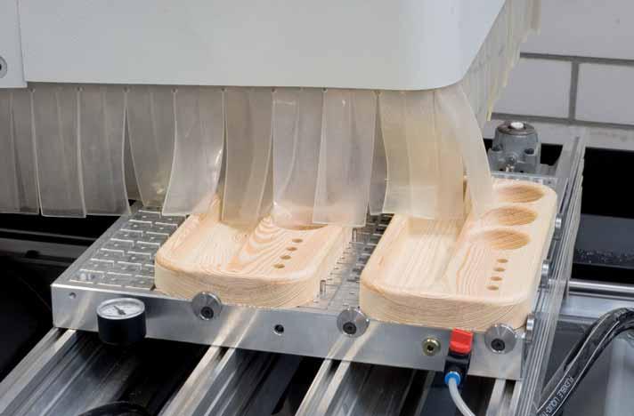
6 THE MOST IMPORTANT ON THE SUBJECT OF VACUUM CLAMPING TECHNOLOGY WHAT IS A VACUUM? A vacuum is the state in a space which is free of matter. In practice, we already call it a vacuum when the air pressure in a space is less than that of the atmosphere. UNITS OF MEASUREMENT USED The most common units are the pascal and the bar. > 100 Pa = 1 hpa > 1 hpa = 1 mbar > 1 mbar = 0,001 bar VACUUM CLAMPING SYSTEMS Vacuum clamping systems are used above all in the wood, plastics and non-ferrous metals industries for quick, simple machining; they are compatible with CNC machine tools. Here vacuum technology is used in connection with special handling systems, for example in order to fix an aluminium plate and machine it from all sides. This increases productivity and cost-effectiveness: the fixing does not cause any damage to the workpiece, and no laborious, timeconsuming aligning of the workpiece is required. The latest clamping systems allow attachments of various sizes and shapes to be exchanged in a very short time, thus facilitating flexible handling of a wide range of workpiece shapes. WHAT DOES VACUUM CLAMPING MEAN? In vacuum clamping, an underpressure is generated under the workpiece being clamped, i.e. a pressure differential is created which presses the workpiece against the clamping plate. Thus the workpiece is not, as one might think, actually sucked, but is rather pressed against the vacuum table. The sliding force of the workpiece depends on its surface structure, the pressure differential and the area on which the vacuum acts. The larger this area is, the better the holding forces. WHY DOES A VACUUM GENERATE A HOLDING FORCE? All surfaces of an object are subjected to an even pressure of approx. 1 bar by the surrounding atmosphere. The integrated Venturi nozzle or an external vacuum pump then removes some of the air from under the workpiece being held, thus removing part of the pressure load on that surface. What remains is a one-sided pressure on the top surface of the workpiece, whose size depends on the degree of the vacuum. Generally it is bar. This means, for example, that a vacuum of 200mbar (absolute pressure) is generated. The pressure differential acting on the workpiece is therefore 800mbar (approx. 0.8 kp/cm). The size of the clamping force is then only dependent on the clamping area. CALCULATION FORMULAE: > Force = Pressure x Area > F (N) = bar x A (m²) x 10 5 > 1 bar = 10 N / cm² 6 STANDARD CLAMPING ELEMENTS


, depending on the specific application.")


7 THE BENEFITS OF AMF VACUUM CLAMPING TECHNOLOGY > The AMF vacuum clamping plate can be operated using compressed air and the integrated Venturi nozzle, or with an external vacuum pump. > The height-adjustable eccentric stops absorb the sliding forces, and can be adjusted individually to the workpiece height. > Easy positioning of workpieces by fastening with stop pins. These also absorb the sliding forces > The sound absorber is integrated into the vacuum clamping plate. We offer two different versions of the sound absorber (No. 7800VSDI and 7800VSD), depending on the specific application. > Lateral grooves allow the vacuum clamping plate to be fastened to a baseplate or onto the machine table using AMF clamps No > Fixtures can be positioned on the vacuum clamping plate with a precision of ±0.01 mm using one locating pin and one diamond pin each > We offer two different versions of the sound absorber (No. 7800VSDI and 7800VSD), depending on the specific application. > Depending on the size of the clamping plate, workpieces can be clamped using more than one suction point. This can also be used to clamp multiple workpieces even different ones. > For efficient changing of the vacuum clamping plate, it can be used in combination with the AMF Zero-Point clamping system. This minimises setup times and increases machine runtime. STANDARD CLAMPING ELEMENTS 7

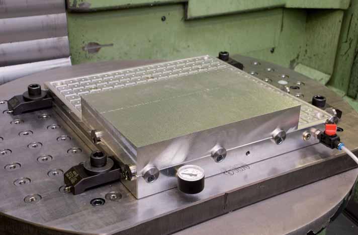
8 Vacuum clamping plates No. 7800X Vacuum clamping plate Included in scope of supply: - Baseplate made of aluminium - Integrated Venturi nozzle - Sound absorber, supplied - Vacuum meter - Shut-off valve - 6 eccentric stops - 2 m pneumatic hose - Plug-in nipple for compressed air connection - 10 m sealing cord Ø 4 mm NEW! Operating Max. vacuum Number of H pressure L B R suction points ±0,1 [bar] [%] [Kg] , , , , , ,5 1, ,5 6, ,5 12, ,5 16, ,5 24,0 Design: The vacuum plate has grooves and suction points on its upper side. By inserting the sealing cord, one or more fields can be defined for the desired workpiece size. All suction points are interconnected. Easy positioning via holes for stop pins or lateral, height-adjustable eccentric stops. Lateral grooves or fastening holes allow the vacuum clamping plate to be fastened to a baseplate (e.g. machine table). Fixture plates can additionally be fixed using a sword or locating pin. It is also no problem to integrate the vacuum clamping plate into the AMF Zero-Point clamping system (see the AMF catalogue Zero-Point Systems ). The workpieces being machined are clamped through generation of a vacuum by means of the integrated Venturi nozzle technology (included in scope of supply) or with an external vacuum pump. By means of individual grid allocation it is also possible to clamp and machine multiple, different workpieces at the same time. Typical applications are milling and grinding operations. The vacuum clamping plate is ready to use right away all of the necessary components are included in the scope of supply. Advantage: - The AMF vacuum clamping plate can be operated using compressed air and the integrated Venturi nozzle, or with an external vacuum pump. - Cost savings through use of the Venturi nozzle - Low compressed air consumption, thus low operating costs Example: 1 m³ of compressed air costs At an average consumption of 40 l/min, this corresponds to /h. - Multiple suction points, thus flexible grid allocation and clamping of multiple parts possible - Vacuum plates can be combined with each other - High holding forces - Universal use - High coefficient of friction allows secure clamping of unmachined workpiece surfaces - Sealing cords compensate for small irregularities in the workpiece surface - Distortion-free, vibration-free five-sided machining Note: Operate only with dried, filtered, non-lubricated compressed air! Max. suction volume against atmosphere: 21.8 l/min. Operating pressure for max. suction volume flow: 3.5 bar. Please observe installation manual On request: Special dimensions 8 STANDARD CLAMPING ELEMENTS

9 Vacuum clamping technology STANDARD CLAMPING ELEMENTS 9


10 Adapter mat No. 7800AMGX Adapter mat, rubber Dimension [mm] Material thickness ±0,2 [mm] x x x x x The sealing cord is placed in the grid of the vacuum clamping plate. It goes up to the end of the area to be worked on in the workpiece. 2. The adapter mat is placed onto the vacuum clamping plate. 3. Holes are made in the adapter mat within the marked clamping surface over a wood plate with a 3-5 mm diameter hole punch. The location of the holes must be in the area of the grid cuts of the vacuum clamping plate. 4. The workpiece to be worked on is placed on it and fixed using the adjustable eccentric stops. Advantage: - The good coefficient of friction offers especially good resistance against the displacement forces that arise during processing. - The adapter mat can be cut into up to 2 mm deep without problem. - If the same contours are used, the adapter mat can be reused almost any number of times, since it does not undergo wear. Workpiece 1 Adapter mat made of rubber 2 Vacuum clamping plate 3 Sealing cord 4 10 STANDARD CLAMPING ELEMENTS

![[Kg] 375097 150x150 10 0,6 374876 300x200 10 1,6 374892 300x400 10 3,3 374900](/docs-images/89/98666372/images/11-2.jpg "400x400 10 4,4 374918 400x600 10 6,6 1.")


11 Adapter plate No. 7800APAX Adapter plate, aluminium Dimension [mm] Material thickness ±0,1 [mm] [Kg] x , x , x , x , x ,6 1. The sealing cord is placed in the grid of the vacuum clamping plate. It goes up to the end of the area to be worked on in the workpiece. 2. The adapter plate is screwed to the vacuum clamping plate. 3. The workpiece to be worked on is placed on it. 4. The workpiece is fixed using the adjustable eccentric stops. Advantage: - The adapter plate can be overcut by up to 2 mm (elimination of cuts). - Preferred uses are for processing thin sheet metal, foils, boards and even paper. Workpiece 1 Adapter plate made of aluminium 2 Vacuum clamping plate 3 Sealing cord 4 STANDARD CLAMPING ELEMENTS 11

12 Surface-mounted block No. 7810ABX Surface-mounted block The following are supplied as standard: - Surface-mounted block from aluminium, grid 12.5 x 12.5 mm - 3 eccentric stops with fixing screws - 1 m sealing cord Ø 2.0 mm NEW! Max. vacuum Number of suction H L B points ±0,1 [%] Design: The surface-mounted block has grooves and a suction point on its upper side. The grid spacing is 12.5 mm. The field size is individually defined by inserting the sealing cord. The surface-mounted block is placed directly over a suction point on the vacuum clamping plate The underside is equipped with a sealing cord Ø 2.0 mm. The use of surface-mounted blocks allows openings for finishing. Workpieces can be through-bored without the vacuum clamping plate or the component itself being damaged. Note: Please order sealing cord Ø 4.0 mm separately (No ). No. 7810APAX Adapter plate, aluminium Suitable for surface-mounted block 7810ABX. NEW! Dimension [mm] Material thickness ±0,1 [mm] x Advantage: - The adapter plate can be milled down to 2 mm (millings on both sides). - Preferred applications are the finishing of thin sheets, foils, PCBs and even paper. No. 7810AMGX Adapter mat, rubber Suitable for surface-mounted block 7810ABX. NEW! Dimension [mm] Material thickness ±0,2 [mm] x Advantage: - The good coefficient of friction offers particularly favourable resistance to the resulting displacement forces during finishing. - Milling down to 2 mm deep in the adapter mat is no problem. - If the same contours are always applied, the adapter mat can be reused any number of times, since they do not suffer any wear. 12 STANDARD CLAMPING ELEMENTS

![initial oil fill - without gas ballast Suction Continuous Motor Vacuum performanction class operation Lubrica- Noise level rating Code [%] [m³/h] [V/Hz] [db (A)] [%] [Kg] 374991 99 15 Oil 230/50](/docs-images/89/98666372/images/13-1.jpg "59 54 100 19 If compressed air is present where the vacuum clamping plate is used, we recommend using the AMF rotary vane vacuum pump.")

 from the vacuum clamping")
13 Accessories No. 7800VPX Rotary vane vacuum pump Included in scope of supply: - suction-side fine-mesh filter - oil mist separator - reversing valve for coarse or fine vacuum operation - anti-vibration buffer - initial oil fill - without gas ballast Suction Continuous Motor Vacuum performanction class operation Lubrica- Noise level rating Code [%] [m³/h] [V/Hz] [db (A)] [%] [Kg] Oil 230/ If compressed air is present where the vacuum clamping plate is used, we recommend using the AMF rotary vane vacuum pump. It ensures reliable continuous operation of the clamping plates used. Due to its small design, the pump can be attached directly to your machine. On request: Other sizes and suction performances are available on request. No. 7800VPFX Liquid separator with vacuum filter included in scope of supply: - Water separator - Vacuum filter - Fastening unit - Ball valve - Coupling plug 1/2 external thread - 15 mm - Plastic tube Ø 15 x 12 mm, length 2 m - Coupler socket - Double nipple Size Connection D100x250 3/ The liquid separator effectively removes condensate (water) from the vacuum clamping system and so protects it from contamination. Advantage: - Removal of 99% of the contained liquid - Maintenance-free - System s operation and maintenance costs are minimised - Easy to install (before the vacuum pump) Note: The set is supplied in the assembled state. Application example: Rotary vane vacuum pump Liquid separator with vacuum filter Vacuum clamping plate STANDARD CLAMPING ELEMENTS 13
14 Accessories No. 7800DX Sealing cord Silicone, anthracite. Shore hardness: Groove width dia. Length [mm] [mm] [m] ,5 ±0, The sealing cord is inserted in the groove to delimit the clamping surface. Advantage: Multiple workpieces can be clamped, even with different sizes. No. 7800VX Vacuum meter Indicators dia. area Connection below [bar] [mm] G1/8 73 No. 7800VDX Sealing ring for vacuum meter Connection G1/8 0,5 Sealing ring is used in installation of the vacuum meter. No. 7800VDSX Vacuum pressure sensor with accessories Electrical connection: Cable with connector according to EN , round design M 8x1, 4-pin, Cable length 0.3 m. Scope of supply consists of: - Pressure sensor - Vacuum hose, outer Ø 4 mm, length 30 cm - Plug connection G1/8-4 Indicators area [bar] Ambient temp. [ C] The threshold values (variable: 2 x relative pressure) are set on the pressure sensor using teaching. If the vacuum pressure drops, the machine is switched off. Advantage: The vacuum pressure sensor serves to monitor the applied air pressure. If the pressure drops, the machine is switched off. This contributes decisively to process reliability. 14 STANDARD CLAMPING ELEMENTS
![Accessories No. 7800EX Eccentric stop, dia. 30 mm Steel, blued. Complete with flat-head screw. dia. [mm] 374538 30 26 Advantage: Individual adjustment to the workpiece height.](/docs-images/89/98666372/images/15-0.jpg "The sliding forces are absorbed by the stop. No. 7800VSDX Sound absorber Housing and absorber insert of PE. Ambient Connection temp.")
15 Accessories No. 7800EX Eccentric stop, dia. 30 mm Steel, blued. Complete with flat-head screw. dia. [mm] Advantage: Individual adjustment to the workpiece height. The sliding forces are absorbed by the stop. No. 7800VSDX Sound absorber Housing and absorber insert of PE. Ambient Connection temp. [ C] G1/ Can be screwed directly into the in vacuum clamping plate. Note: Check sound absorber regularly for fouling. No. 908X-G1/8 Screw plug with rubber seal Connection G1/8 7 No. 7800VAFX Suction filter Housing of brass, filter insert of tin bronze. Connection G1/8 2 The suction filter is screwed into the vacuum clamping plate. Note: Check suction filter regularly for fouling. STANDARD CLAMPING ELEMENTS 15
![Accessories No. 7800AVX Ball-Valve manually operated. Hose dia. Connection [mm] 374587 G1/8 6 40 The hand valve is screwed into the plate directly. With O-ring seal. No. 7800VNSX Plug-in nipple for quick coupling with cap nut DN7.](/docs-images/89/98666372/images/16-0.jpg "2. Brass. Hose dia., outer [mm] 374595 6 17 Advantage: Easy connection with the pneumatic hose of the vacuum clamping plate. No. 7800ZSX ISO 8734-4x12-A cylinder pin Steel.")
![Packaging unit [St] 374603 10 15 Easy positioning of workpieces by fastening in the holes provided in the vacuum clamping plate.](/docs-images/89/98666372/images/16-1.jpg "Advantage: The sliding forces are absorbed by the stop. No. 2800WX-06 Pneumatic hose Hose dia. Length [mm] [m] 374611 6 10 300 16 STANDARD CLAMPING ELEMENTS")
16 Accessories No. 7800AVX Ball-Valve manually operated. Hose dia. Connection [mm] G1/ The hand valve is screwed into the plate directly. With O-ring seal. No. 7800VNSX Plug-in nipple for quick coupling with cap nut DN7.2. Brass. Hose dia., outer [mm] Advantage: Easy connection with the pneumatic hose of the vacuum clamping plate. No. 7800ZSX ISO x12-A cylinder pin Steel. Packaging unit [St] Easy positioning of workpieces by fastening in the holes provided in the vacuum clamping plate. Advantage: The sliding forces are absorbed by the stop. No. 2800WX-06 Pneumatic hose Hose dia. Length [mm] [m] STANDARD CLAMPING ELEMENTS


17 Accessories No. 7800VABX Locating pin Steel. A B C D E F G H J M5 10 R4 30 Advantage: Quick, precise alignment of the fixtures being clamped. No. 7800VSBX Sword pin Steel. A B C D E F G H J K M5 10 R4 4,3 23 The sword pin is used for tolerance compensation (±0.01). Advantage: Quick, precise alignment of the fixtures being clamped. No Clamps for machine vices Tempering steel, blued, packaged in pairs. for clamp. for clamp. for jaw B1 L A A1xA2 H screw metric screw inch width ,5 78 M12, 14, 16 1/2, 5/ ,5 10x5, STANDARD CLAMPING ELEMENTS 17
18 Accessories No. 6370ZNX-20 Clamping nipple for clamping modules K20 Hardened, for hydraulic and pneumatic clamping modules (size K20). dia. DN dia. D1 dia. D2 H H1 T Size K K K Design: : Zero point nipple : Slit nipple : Undersized nipple Note: Our complete zero point clamping programme can be found in our catalogue Zero-Point-Systems No. 6370ZNSX-001 Engagement nipple screw Strength class Size M L L K20 M On request: Engagement nipple screws in various lengths and materials (e.g. high-grade stainless steel). Dimensions for machining nipple mountings Size dia. D1 dia. M S1 S2 Figure: K20 25 M12 5,5 23 Shown with clamping nipple and engagement nipple screw. 18 STANDARD CLAMPING ELEMENTS

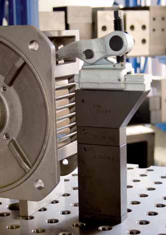
19 THE POWER CLAMP THAT KEEPS ITS PROMISES > Material: Robust clamping element made of alloyed tempered and forged steel > Applications: All clamping tasks in cutting and non-cutting finishing operations > Features: > Clamping force of up to 25 kn > Two joints for minimal wear > Chip-deflecting design > Simple installation in T-slots or on grid plates When using clamps in non-cutting and cutting metal finishing processes, as well as in mould making, clamping force and precision that meet the highest demands are required. With the sliding power clamp made of alloyed tempered steel, we offer an exceptionally robust and versatile mechanical clamping element, which can achieve extremely high clamping force of up to 25 kn. The power clamp, which is usable both horizontally and vertically, can be fastened to regular T-slot tables using T-nuts or, alternatively, to grid pallets using threaded mounting. > Robust and powerful but easy to use - the power clamp that keeps its promises. STANDARD CLAMPING ELEMENTS 19

![Components: - Base element - Carrier element max. load Size G H min. H max. [kn] 372961 16 16 M12 11 48 1240 373894 25 25 M12 0 63 2943 373902 25 25 M16 0 63 2922 1.](/docs-images/89/98666372/images/20-1.jpg "Position and fasten carrier element on the tool plate 2. Push the base element into the desired position on the carrier table.")


20 Power Clamp for injection moulding No. 7500K Power Clamp for injection moulding Complete with mounting. Robust clamping element made of alloyed tempered steel, forged, for variable clamping heights, with sliding base element. Components: - Base element - Carrier element max. load Size G H min. H max. [kn] M M M Position and fasten carrier element on the tool plate 2. Push the base element into the desired position on the carrier table. After this is done, it is ready for operation. 3. Adjust the height of the clamping arm with the adjusting bolt and clamp the tool. 4. The very robust design enables quick and easy clamping. Advantage: - Max. load 16 kn / 25 kn - Two joints for minimal wear - Use on tool plates with T-grooves and pitch - Low installation height provided by adjusting bolt with hexagon socket Note: To reduce wear to the adjusting bolt, we recommend using AMF screw compound No It possesses a synergistic combination of highly-effective solid lubricants and is heat-resistant and does not wash out. Dimensions Size A A1 B B1 C G1 K L1 L2 SW , M , M , M STANDARD CLAMPING ELEMENTS
![Power Clamp for injection moulding Reference formulae for the number of power clamps on injection moulding machines Power Clamp Tool Legend: FG = [kn] FSW = Required tool clamping force on basis of](/docs-images/89/98666372/images/21-0.jpg "tool weight [kn] FSP = Max.")
21 Power Clamp for injection moulding Reference formulae for the number of power clamps on injection moulding machines Power Clamp Tool Legend: FG = [kn] FSW = Required tool clamping force on basis of tool weight [kn] FSP = Max. load of power clamp [kn] (see 7500K) FSP1 = Difference between FSP and FV [kn] FV = Pre-tensioning force of power clamp [kn] FÖFFN = Opening force of injection moulding machines [kn] (see datasheet on injection moulding machine) g = Acceleration (9,81 m/s²) m = Tool mass [Kg] n1 = No. of power clamps required on basis of tool weight n2 = No. of power clamps required on basis of opening force μ = Friction coefficient (~0,14) Reference formulae: 1. Calculation of weight [kn]: FG = m x g Calculation of tool force [kn]: FSW = FG μ 3. No. of power clamps required on basis of tool weight: n1 = FSW 4. No. of power clamps required on basis of opening force: 5. Result = comparison between n1 and n2 Use the larger figure FSP1 n2 = FÖFFN FSP1 Torque/force path 7500S-16 No. 7500S-25 Tightening torque [Nm] ,5 19 Clamping force [kn] Clamping force [kn] STANDARD CLAMPING ELEMENTS 21


22 Power Clamp, sliding No. 7500S Power Clamp, sliding complete with mounting Robust clamping element made of alloyed tempered steel, forged, for variable clamping heights, with sliding base element. Components: - Base element - Carrier element - Thrust piece with smooth surface - Mounting kit No. 7500BF Size = clamping G Slot H min. H max. force [kn] M M M M M M M M M M Position and fasten carrier element on the tool table. 2. Push the base element into the desired position on the carrier element. After this is done, it is ready for operation. 3. Adjust the height of the clamping arm with the adjusting bolt and clamp the workpiece. 4. The very robust design enables quick and easy clamping. Advantage: - Up to 16 kn / 25 kn clamping force - Two joints for minimal wear - Chip-deflecting design mm T-grooves or M12 and M16 grid pallets - 4 thrust-piece variants - Variable clamping height, mm Note: When size 16 and size 25 are employed and the Power Clamp is inserted parallel to the groove, mounting kit 7500BF must be used with the base element for grooves size 18 or greater. To reduce wear to the adjusting bolt, we recommend using AMF screw compound No It possesses a synergistic combination of highly-effective solid lubricants and is heat-resistant and does not wash out. Dimensions Size A A1 B B1 C G1 K L1 L2 SW , M , M , M , M , M , M , M , M , M , M STANDARD CLAMPING ELEMENTS


23 Power Clamp, sliding No. 7500E Power Clamp with Spacer element, sliding complete with mounting Clamping force 25 kn. Robust clamping unit made of alloyed tempered steel, forged, for variable clamping heights, with sliding base element. Components: - Base element - Spacer element - Thrust piece with smooth surface - Mounting kit No. 7500BZ G Slot H min. H max. A1 A2 K M M M M M M M M M M M M M M Position and secure the spacer element on the tool table. 2. Push the base element (base body and clamping arm) into the desired position on the spacer element. It is then ready for operation. 3. Adjust the height of the clamping arm with the adjusting bolt and clamp the workpiece. 4. The very robust design facilitates a quick and easy clamping. No. 7500G Base Element with hexagon head or socket. Tempered steel, hardened. Size = clamping SW SW Slot force outside inside [kn] STANDARD CLAMPING ELEMENTS 23


24 Power Clamp 24 STANDARD CLAMPING ELEMENTS

![A B C L1 L2 force [kn] 372904 16 M12 14-18 15 52 5 35 100 12 23 115 74153 25 M12 14-18 3 69 8 45 135 16 25 314 74161 25 M16 18-28 3](/docs-images/89/98666372/images/25-2.jpg "69 8 45 135 20 30 304 Note: Mounting kits 7500BZ, comprising cylinder-head bolt of grade 12.")

![A B C L1 force [kn] 79715 25 M18 3 69 8 45 135 16 425 79723 25 M20 3 69 8 45 135 16 440 79277 25 M24 3 69 8 45 135 16 472 No.](/docs-images/89/98666372/images/25-4.jpg "7110M-**-2 Adapter element for Block Clamping System 7110. For power Size A B C I L H min. H max.")

25 Accesoires - Power Clamp No. 7500F Foot element Complete with mounting screw. Tempered steel, hardened. Recommended use: groove size 16 and greater for size 16; groove size 25 and greater for size 18. Size = clamping G Slot H min. H max. A B C L1 L2 force [kn] M M M Note: Mounting kits 7500BZ, comprising cylinder-head bolt of grade 12.9 and T-groove key DIN 508, are not included in pack. No. 7500A Adapter element for M18, M20 and M24 positioning holes. Tempered steel, hardened. Consists of spacer plate, adapter screw and cylinder screw ISO 4762-M12. Size = clamping G H min. H max. A B C L1 force [kn] M M M No. 7110M-**-2 Adapter element for Block Clamping System For power Size A B C I L H min. H max. clamps, large , , Through the combined use of the adapter element with Power Clamp No and Block Clamping System No. 7110, large clamping heights can be achieved. Note: Additional elements of the AMF Block Clamping System can be found in our AMF catalogue Clamping and fixture systems. STANDARD CLAMPING ELEMENTS 25


![A B C L1 force [kn] 74120 25 M12 14-18 60 120 90 40 150 23 2520 74484 25 M16 18-28 60 120 90 40 150 23 2520](/docs-images/89/98666372/images/26-3.jpg "74476 25 M12 14-18 120 180 150 40 150 23 4020 74492 25 M16 18-28 120 180 150 40 150 23 4020 Note: Mounting kits")


26 Accesoires - Power Clamp No. 7500T Carrier Tempering steel, hardened. Size = clamping G Slot A C E H L1 L2 force [kn] M , M , M , M , Note: Mounting kits 7500BZ, comprising cylinder-head bolt of grade 12.9 and T-groove key DIN 508, are not included in pack No. 7500Z Spacer element Tempering steel, hardened. Size = clamping G Slot H min. H max. A B C L1 force [kn] M M M M Note: Mounting kits 7500BZ, comprising hexagonal bolt ISO , washer DIN 6340 and T-groove key DIN 508, are not included in pack. No. 7500D Pressure pad complete with dowel pin. Stainless steel, 7500DG smooth contact surface, 7500DR wavy contact surface, 7500DL contact surface for cyl. workpieces, lengthwise, 7500DQ contact surface for cyl. workpieces, transverse. Size = clamping Form A B C force [kn] DG ,5 9, DG ,5 19, DR ,5 17, DL ,5 24, DQ ,5 25, / STANDARD CLAMPING ELEMENTS


![Size = clamping for for G Slot L force 7500S 7500S+7500F [kn] 372979 16 M12 14 35 X - 81 372987 16 M12 16 40 -](/docs-images/89/98666372/images/27-3.jpg "X 107 372995 16 M12 18 45 - X 138 79590 25 M12 14 45 X - 98 79608 25 M12 14 50 - X 100 79616 25 M12 16 45 X -")


27 Accesoires - Power Clamp No. 7500SP Clamping Bolt Set Hex head or socket, consisting of ball-thrust bolt, supporting bolt and 2 pins. Tempering steel, hardened. Size = clamping SW SW G1 L force outside inside [kn] M M M M No. 7500BF Mounting kit for carrier element comprising hexagonal bolt grade 12.9 and T-groove key DIN 508. Size = clamping for for G Slot L force 7500S 7500S+7500F [kn] M X M X M X M X M X M X M X M X M X M X M X M X M X M X M X M X M X M X X 537 No. 7500BZ Mounting kit for intermediate element comprising hexagonal bolt ISO , washer DIN 6340 and T-groove key DIN 508. Size = clamping G Slot L force [kn] M M M M M M M M STANDARD CLAMPING ELEMENTS 27


28 Power Clamp for injection moulding By kind permission of Robert Bosch GmbH in Waiblingen By kind permission of Robert Bosch GmbH in Waiblingen 28 STANDARD CLAMPING ELEMENTS


29 CLAMPING WITH SINGLE CLAMPS OR WITH COMPACT CLAMPING UNITS > Material: Tempering steel to DIN regulations. > Machining: Plane-parallel base- and clamping faces ensure safe force transmission. > Temperin: According to DIN regulations. > Finishing: All clamps are abrasionproof quality varnished, or of equal quality finish. Where high clamping forces or flexible adaption to shapes and sizes of workpieces are demanded, we offer our single clamps or clamping combinations by using our adjustable clamps. All AMF-clamps shown in this catalogue be combined with different support blocks and are therefore adaptable to different shaped and sized workpieces. The Advantages of these adjustable clamps are theire unsiversal application abilities for single parts up to medium series production with changing clamping dimensions. They allow simple and fast horizontal and vertical application, are interchangeable and price worthy. Their compact design ensures high clamping forces even at large clamping dimensions. STANDARD CLAMPING ELEMENTS 29

.")
30 Crocodile No. 6312V Crocodile clamp with counterholder, adjustable Continuously adjustable, tempered, galvanized, with undetachable compression piece and back support. NEW! Clamping force B1 Slot max.* H1 [kn] , 12, , 14, 16, , 18, 20, , 22, 24, * Specified clamping forces in optimal clamping position (smallest distance from the clamping screw to the clamping point). Clamping forces can vary depending clamping, strength class of the clamping screw and condition of the thread (lubrication). The crocodile is used for all clamping tasks over T-grooves and Nuten und threaded holes. The compression piece and the counterholder are connected undetachably to the clamping shoe, and so the crocodile can be used quickly. The clamping plate is equipped with two clamping surfaces and can be easily turned depending on use. As a result, all non-cutting and cutting processing types (e.g. injection moulding and presses) are covered. Advantage: - Possibility of variable and quick adjustment at a distance from the workpiece - Use in all areas of cutting and non-cutting processing - Especially suitable for use on injection moulding machines and presses - No additional supports to achieve the required clamping height - Compression piece and counterholder are connected undetachably to the clamping shoe - The crocodile clamping element can be variably expanded for every clamping height. Note: Your choice of tensioning screws DIN 787, stud screws DIN 6379 and the cylinder screws DIN 912 can be used for clamping. Greater clamping heights can be achieved through use of the support extension 6312S. Dimensions A A1 A2 B2 x L B3 E1 E2 H2 K x x x x STANDARD CLAMPING ELEMENTS

![* H1 DIN 787 [kn] 79780 13 10 M10x10x100 25 0-40 613 79806 13 12 M12x12x125 30 0-55 686 79822 13 14 M12x14x125 30 0-55 705 79848 17 12 M12x12x160 35 0-70 1591 79863 17 14 M12x14x160 35 0-70 1610](/docs-images/89/98666372/images/31-1.jpg "79889 17 16 M16x16x160 40 0-70 1798 79905 17 18 M16x18x160 40 0-70 1818 79921 21 16 M16x16x200 55 0-80 2715 79210 21 18 M16x18x200 55 0-80 3018 79228 21 20 M20x20x200 60 0-80 3018 374926 21 22")
31 Crocodile No. 6312V Crocodile clamp with counterholder, adjustable cpl. with clamping bolt DIN 787, washer DIN 6340 and nut DIN 6330B. Infinitely adjustable, tempered, galvanised with captive compression piece and counter bearing. NEW! Clamping Clamping bolt B1 Slot force max.* H1 DIN 787 [kn] M10x10x M12x12x M12x14x M12x12x M12x14x M16x16x M16x18x M16x16x M16x18x M20x20x M20x22x M20x20x M20x22x M24x24x M24x28x * Specified clamping forces in optimal clamping position (smallest distance from the clamping screw to the clamping point). Clamping forces can vary depending clamping, strength class of the clamping screw and condition of the thread (lubrication). The crocodile is used for all clamping tasks over T-grooves and Nuten und threaded holes. The compression piece and the counterholder are connected undetachably to the clamping shoe, and so the crocodile can be used quickly. The clamping plate is equipped with two clamping surfaces and can be easily turned depending on use. As a result, all non-cutting and cutting processing types (e.g. injection moulding and presses) are covered. Advantage: - Possibility of variable and quick adjustment at a distance from the workpiece - Use in all areas of cutting and non-cutting processing - Especially suitable for use on injection moulding machines and presses - No additional supports to achieve the required clamping height - Compression piece and counterholder are connected undetachably to the clamping shoe - The crocodile clamping element can be variably expanded for every clamping height. Note: For missing dimensions, see No. 6312V. Dimensions A A1 A2 B2 x L B3 E1 E2 H2 K x x x x x x x x x x x x x x x STANDARD CLAMPING ELEMENTS 31

![* H1 DIN 6379 6312V [kn] 375766 13 M12x100-30 0-30 639 375782 13 M12x125-30 0-55 659 375808 17 M12x125-40 0-50 1535 375824 17 M12x160-40 0-70 1558 375840 17 M16x125-40 0-40 1660 375865 17 M16x160-40](/docs-images/89/98666372/images/32-2.jpg "0-70 1718 375881 21 M20x160-60 0-40 2754 375907 21 M20x200-60 0-80 2834 375923 25 M20x200-75 0-70 4072 375949 25 M20x250-75 0-100 4172 375964 25 M24x200-75 0-50 4374 375980 25 M24x250-75 0-100 4524")
.")
32 Crocodile No. 6312V Crocodile clamp with counterholder, adjustable cpl. with stud bolt DIN 6379, washer DIN 6340 and nut DIN 6330B. Infinitely adjustable, tempered, galvanised with captive compression piece and counter bearing. NEW! Clamping Clamping bolt Support extension B1 force max.* H1 DIN V [kn] M12x M12x M12x M12x M16x M16x M20x M20x M20x M20x M24x M24x M20x250 M16x M20x315 M16x M20x315 M20x M20x400 M20x M24x315 M20x M24x400 M20x * Specified clamping forces in optimal clamping position (smallest distance from the clamping screw to the clamping point). Clamping forces can vary depending clamping, strength class of the clamping screw and condition of the thread (lubrication). The crocodile is used for all clamping tasks over T-grooves and Nuten und threaded holes. The compression piece and the counterholder are connected undetachably to the clamping shoe, and so the crocodile can be used quickly. The clamping plate is equipped with two clamping surfaces and can be easily turned depending on use. As a result, all non-cutting and cutting processing types (e.g. injection moulding and presses) are covered. Advantage: - Possibility of variable and quick adjustment at a distance from the workpiece - Use in all areas of cutting and non-cutting processing - Especially suitable for use on injection moulding machines and presses - No additional supports to achieve the required clamping height - Compression piece and counterholder are connected undetachably to the clamping shoe - The crocodile clamping element can be variably expanded for every clamping height. Note: For missing dimensions, see 6312V. Dimensions A A1 A2 B2 x L B3 E1 E2 H2 K x x x x x x x x x x x x x x x x x x STANDARD CLAMPING ELEMENTS


 Groove 18 Clamping force 40 kn B1 = 17 Crocodile order 79798 2) For a clamping height of 125 mm, support extension 6312S is used (table P.")
33 Support extension No. 6312V Support extension Hardened and zinc-plated steel, hardened support screw, strength class 8.8 Consisting of compression piece, support screw and fastening bolts. NEW! D x LS A B C D1 E G H K M10x M M12x M M12x M M16x M M16x M M20x M M20x M The support extension is screwed to the counterholder of the crocodile to increase the clamping height. Advantage: Continuous adjustment of clamping heights. The right size for your application is always available, order example 6312V, without clamping bolt Requirements: Table groove 18 / required clamping height: 125 mm / required clamping force: 35 kn 1) Select clamp 6312V (order table P. 30) Groove 18 Clamping force 40 kn B1 = 17 Crocodile order ) For a clamping height of 125 mm, support extension 6312S is used (table P. 34, bottom) B1 = 17 Groove 18 Clamping height 125 mm (clamping range mm) DxLS = M12x94 Support extension order (table P. 33, above) 3) Size of the T-groove bolt DIN787, complete with washer and hexagon nut M16x18x STANDARD CLAMPING ELEMENTS 33
34 Crocodile Installation recommendations and dimensions when using the clamping bolt DIN 912 (without support extension 6312S) B Dimension DIN 912 G x L Clamping height H1 Thread depth T M10x M10x M10x M12x M12x M12x M12x M12x M12x M16x M16x M16x M16x M16x M16x M20x M20x M20x M20x M20x M20x M24x M24x M24x Installation recommendations and dimensions when using the clamping bolt DIN 787 (with support extension 6312S) B1 D x LS Dimension DIN 787 Clamping range H1 13 M10x49 M10x10x M10x49 M12x12x M10x49 M12x14x M12x49 M12x12x M12x49 M12x14x M12x49 M16x16x M12x49 M16x18x M12x94 M12x12x M12x94 M12x14x M12x94 M16x16x M12x94 M16x18x M16x55 M16x16x M16x55 M16x18x M16x55 M20x20x M16x55 M20x22x M16x90 M16x16x M16x90 M16x18x M16x90 M20x20x M16x90 M20x22x M20x69 M20x20x M20x69 M20x22x M20x69 M24x24x M20x69 M24x28x M20x109 M20x20x M20x109 M20x22x M20x109 M24x24x M20x109 M24x28x STANDARD CLAMPING ELEMENTS


35 Clamps No. 6313K Clamp short with saddle (without clamping bolt) continuously adjustable, tempered, galvanized and blue passivated. B1 Slot clamp. screw B2 x L D E1 E2 H1 H2 K x x x x x M12x12x100 38x M12x14x100 38x M16x16x160 56x M16x18x160 56x M20x20x200 66x Note: Suitable fastening elements: DIN 787 clamping bolts, DIN 6340 washers and DIN 6330B hexagon nuts. No. 6313L Goose-neck clamp long with saddle (without clamping bolt) continuously adjustable, tempered, galvanized and blue passivated. for clamp. B1 Slot B2 x L B3 E H1 H2 H3 K screw M20 66x M24 76x M30 90x Note: Suitable fastening elements: DIN 787 clamping bolts and DIN 6331 hexagon nuts. STANDARD CLAMPING ELEMENTS 35

36 Clamps for machine vices No Clamps for machine vices Tempering steel, blued, packaged in pairs. for clamp. for clamp. for jaw B1 L A A1xA2 H screw metric screw inch width ,5 78 M12, 14, 16 1/2, 5/ ,5 10x5, ,5 78 M12, 14, 16 1/2, 5/8 125/160 27,5 10x6, No Clamps for machine vices Forged design, packaged in pairs. for clamp. for clamp. for jaw B1 L A A1xA2 H screw metric screw inch width ,5 78 M12, 14, 16 1/2, 5/ ,5 10x5, ,5 78 M12, 14, 16 1/2, 5/8 125/160 27,5 10x6, STANDARD CLAMPING ELEMENTS


37 Clamps No. 6314V Tapered clamp with adjusting support screw Tempering steel, varnished. sim. Slot H* DIN6314 clamp. screw D x LS A B2 E1 E2 B1xL x80 - M10x x100 - M12x x100 - M12x x125 - M16x x125 - M16x x160 - M20x x160 - M20x x200 - M24x x200 - M24x x250 - M24x x250 - M24x x315 - M30x x400 - M30x x80 M10x10x80 M10x x100 M12x12x100 M12x x100 M12x12x160 M12x x100 M12x14x100 M12x x100 M12x14x160 M12x x125 M16x16x125 M16x x125 M16x16x160 M16x x125 M16x18x125 M16x x125 M16x18x160 M16x x160 M20x20x160 M20x x160 M20x20x200 M20x x160 M20x22x160 M20x x160 M20x22x200 M20x x250 M24x28x200 M24x x250 M24x28x250 M24x x315 M30x36x315 M30x x400 M36x42x400 M30x *depending on depth of slot to DIN 650 and position of fixture nut. Clamps without T-bolts are same item for sizes 12 and 14, 16 and 18, 20 and 22, each. No. 6316V Cranked clamp with adjusting support screw Tempering steel, varnished. sim. Slot H* DIN6316 clamp. screw D x LS A B2 E1 E2 B1 x L x100 - M10x x125 - M12x x160 - M16x x200 - M20x x200 - M24x x100 M10x10x80 M10x x125 M12x12x100 M12x x125 M12x14x100 M12x x160 M16x16x125 M16x x160 M16x18x125 M16x x200 M20x20x160 M20x x200 M20x22x160 M20x *depending on depth of slot to DIN 650 and position of fixture nut. Clamps without T-bolts are same item for sizes 12 and 14, 16 and 18, 20 and 22, each. STANDARD CLAMPING ELEMENTS 37


38 Stepped clamps No. 6314AV Stepped clamp with adjusting support screw Tempering steel, varnished. sim. Slot H* DIN6314 clamp. screw D x LS A A1xA2 B2 E1 E2 B1xL x100 - M12x x10, x125 - M16x x12, x160 - M20x x15, x100 M12x12x100 M12x x10, x100 M12x14x100 M12x x10, x125 M16x16x125 M16x x12, x125 M16x18x125 M16x x12, x160 M20x20x160 M20x x15, x160 M20x22x160 M20x x15, *depending on depth of slot to DIN 650 and position of fixture nut. To clamp thin parts, turn the clamp over. Clamps without T-bolts are same item for sizes 12 and 14, 16 and 18, 20 and 22, each. No. 6315V Stepped clamp with adjusting support screw Tempering steel, varnished. sim. DIN 6315B B1 x L clamp. screw D x LS A B2 E2 Slot H* x100 - M10x x125 - M12x x160 - M16x x200 - M20x x100 M10x10x 80 M10x x125 M12x12x100 M12x x125 M12x14x100 M12x x160 M16x16x125 M16x x160 M16x18x125 M16x x200 M20x20x160 M20x x200 M20x22x160 m20x *depending on depth of slot to DIN 650 and position of fixture nut. To clamp thin parts, turn the clamp over. 38 STANDARD CLAMPING ELEMENTS


39 Support screws and detent clamp lever No. 6314S Support screw Hardened, strength class 8.8 Suitable for all lockable clamps. D x LS D1 K M10x M12x M12x M16x M16x M20x M20x M24x M24x M30x No Detent clamp lever Steel, blued. Suitable for adjustable clamps 6313K, 6314V, 6315V, 6316V and G D H L M M STANDARD CLAMPING ELEMENTS 39


40 Step clamps No Step clamp Special cast iron, screw and bushing 8.8. Size Slot B C H L S , , , , , , , , , , , , , , , , , , , , , , Clamping unit for quick application. The spiral serration allows fast adjusting to any work height up to 320 mm. Low space requirement on machine table due to compact design. 40 STANDARD CLAMPING ELEMENTS


 clamping height with clamps nos. 6321-12 and 6321-14, DIN787 T-slot bolts 160 mm long must be used.")
41 Stepless height adjustable clamps No Stepless height adjustable clamp Steel, forged and tempered, zinc-plated. Slot B1 B2 x L D E1 E2 H clamp. screw x x x M12x12x x M12x14x x M16x16x x M16x18x x M20x20x x M20x22x Stepless clamp for fast coverage of several ranges of work height without additional supports. Low space requirement on machine table. Heavy-duty design and specially suitable for clamping of press- and punching tools. Note: To achieve the full (75 mm) clamping height with clamps nos and , DIN787 T-slot bolts 160 mm long must be used. STANDARD CLAMPING ELEMENTS 41


 70 26 35 105 3850 70110 33 250 M30 1 1/4 40 80 34 45 100 5000 70128 33 315 M30 1 1/4")
42 Plain clamps DIN 6314 Plain clamp Tempering steel, varnished. for clamp. for clamp. B1 L A B2 B3 E1 E2 screw metric screw inch ,6 50 M6 1/ M8 5/ M10 3/ M12 M14 1/ M12 M14 1/ M16 M18 5/ M16 M18 5/ M20 M22 3/ M20 M22 3/ M M24 1 (35) M30 1 1/ M30 1 1/ (43) 400 M36 M42 1 1/ ( ) not to DIN 42 STANDARD CLAMPING ELEMENTS
43 Step clamps and forked clamps No. 6314Z Step clamp Tempering steel, varnished. Only match step blocks 6500E. The longer versions are used for large clamping distances due to large T-slot distance or enlarged work depth, i.e. on graving machines. for clamp. for clamp. B1 L A B2 B3 E1 E2 screw metric screw inch ,6 50 M6 1/ ,6 80 M6 1/ M8 5/ M8 5/ M10 3/ M10 3/ M12 M14 1/ M12 M14 1/ M16 M18 5/ M16 M18 5/ M20 M22 3/ M DIN 6315B Forked clamp tapered Tempering steel, varnished. for clamp. for clamp. B1 L A B2 B3 B4 screw metric screw inch ,6 60 M6 1/ M8 5/ M10 3/ M12 M14 1/ M12 M14 1/ M12 M14 1/ M16 M18 5/ M16 M18 5/ M16 M18 5/ M20 M22 3/ M20 M22 3/ M20 M22 3/ M20 M22 3/ M M M M M M M M30 1 1/ M30 1 1/ M30 1 1/ M30 1 1/ M30 1 1/ M36 1 1/ M36 1 1/ (43) 600 M36 M42 1 1/ ( ) not to DIN STANDARD CLAMPING ELEMENTS 43
44 Forked clamps No. 6315GN Forked clamp with shoe Tempering steel, varnished. for clamp. for clamp. B1 L1 A B2 B3 L2 L3 screw metric screw inch M8 5/ M10 3/ M12 M14 1/ M12 M14 1/ M16 M18 5/ M16 M18 5/ M20 M22 3/ M20 M22 3/ M M M30 1 1/ M30 1 1/ DIN 6315C Forked clamp with pin end Tempering steel, varnished. for clamp. for clamp. B1 L1 A B2 D L2 L3 screw metric screw inch M8 5/ M10 3/ M12 M14 1/ M12 M14 1/ M16 M18 5/ M16 M18 5/ M20 M22 3/ M20 M22 3/ M M M30 1 1/ M30 1 1/ STANDARD CLAMPING ELEMENTS


45 Goose-neck clamps DIN 6316 Single goose-neck clamp Tempering steel, varnished. for clamp. for clamp. B1 L A B2 B3 C E1 E2 H screw metric screw inch ,6 60 M6 1/ M8 5/ M10 3/ M12 M14 1/ M16 M18 5/ M16 M18 5/ M20 M22 3/ M20 M22 3/ M24 1 (35) (28) M24 1 (35) (28) M30 1 1/ M30 1 1/ (43) 400 M36 M42 1 7/16 1 1/ ( ) not to DIN No Double goose-neck clamp Tempering steel, varnished. for clamp. B1 L A B2 B3 C E H screw M12-M M20-M These clamps to match with large washer DIN 6340 or DIN 6319G. STANDARD CLAMPING ELEMENTS 45

![Tightening Clamping force torque Slot G H [kn] [Nm] 73999 15 70 18 M12 20-35 840 73981 25 170 22 M16 30-45](/docs-images/89/98666372/images/46-1.jpg "2126 79194 50 320 28 M20 40-53 5000 Used for clamping outside of the tool table.")

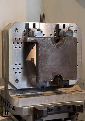
46 Clamping unit No. 6314AT Clamping unit to clamp outside of the tool table Tempered steel. Infinitely adjustable. Tightening Clamping force torque Slot G H [kn] [Nm] M M M Used for clamping outside of the tool table. For use when clamping large workpieces or tools that do not allow any space for clamping elements on the tool or machine table. Note: For the installation dimensions of the clamp, see No. 7110GX-**-1. Do not use on presses! Dimensions A L K1 K2 SW1 SW STANDARD CLAMPING ELEMENTS


47 Clamps No. 7110GX-**-1 Clamp, straight tempered. Size A x B E F G I K N x ,5 M12 21,5 11, x ,0 M16 28,0 15, x ,0 M20 38,0 21, No. 7110GLX-**-1 Clamp, straight (long) with screw-in pin end tempered. Size A x B E F G I K L M N x35, ,5 M x45, ,0 M x60, ,0 M No. 7110DX-**xM** Set screw ball-shaped, strength class Size G x L H SW xM12 M12x xM16 M16x No. 7110DMX-**xM** Set screw ball-shaped, brass, with steel nut. Size G x L H SW xM12 M12x xM16 M16x STANDARD CLAMPING ELEMENTS 47


48 Set screws No. 7110DHX-**xM** Set screw with flat-faced ball, adjustable, ribbed. Size G x L H dia. K SW1 SW xM8 M8x25 11,6 5, xM12 M12x35 15,7 8, xM16 M16x40 20,7 10, xM20 M20x50 27,3 20, No. 7110DIX-**xM** Set screw with flat-faced ball, adjustable, plain. Size G x L H dia. K SW1 SW xM8 M8x25 11,6 5, xM12 M12x35 15,7 8, xM16 M16x40 20,7 10, xM20 M20x50 27,3 20, No. 7110DKX-**xM** Set screw with flat-faced ball. Size G x L H dia. l dia. K SW xM8 M8x , xM12 M12x , xM16 M16x , xM20 M20x , No. 7110DFX-**xM** Set screw with flat-faced ball, ribbed. Size G x L H dia. l dia. K SW xM8 M8x , xM12 M12x , xM16 M16x , xM20 M20x , STANDARD CLAMPING ELEMENTS


49 Clamps STANDARD CLAMPING ELEMENTS 49


50 THE BLOCK-CLAMPING SYSTEM ELIMINATES HEAVY CLAMPING THANKS TO EASE OF HANDLING For quick and safe clamping of workpieces at various heights, block-clamping systems are ideal for use on milling machines, CNC machines, machining centres and fixture systems, as they are > easy to set up > quick when tool changing > reliable when clamping > economical when removed Further advantages: > Infinite adjustment to the correct workpiece height due to slide-in intermediate elements. > Stable and immovable position for horizontal or vertical use.. > Quick clamping and unclamping of the workpiece using just one bolt. No. 7200BB Block-clamping system basic set Consists of: - 2 clamping units size 16-2 spacer elements 100 mm high - 4 spacer elements 50 mm high - 2 fastening sets each for grooves 18, 20, 22-1 adapter key width 24 Dimensions of case Size Slot LxWxH [Kg] , 20, x 400 x ,5 1. Position base element on machine table on workpiece. Position spacer element on base element using tension rods. 2. Push spacer element downwards. 3. Swivel spacer element in until it locks into place. Repeat this up to the required clamping height. Lastly, mount head element. 4. Turn tombstone to desired clamping position and secure on base element. Tighten clamping bolt for clamping. Advantage: - Low weight - advantages for assembly and handling. - The contours of the basic elements and the open design mean hardly any projecting edges. - Very low maintenance requirements, because all parts are easily accessible. - Easy to grip - can be gripped securely even when wearing gloves, when oily and dirty. - Elements are easy to combine in any position. - Thanks to a minimum number of different parts and systematically modular design, the AMF block-clamping system 7200 is more economical than comparable blockclamping systems. - The system is very secure. The sturdy interfaces and the minimal expansion of the tension rods mean that almost all of the torque is transmitted to the workpiece. This ensures high clamping forces. Note: - By exchanging the T-nuts the system is suitable for various T-grooves. - Tension rod of hardened and tempered steel - Body of aluminium - All parts are exchangeable. - Subsequent height extension possible through purchase of additional standardised spacer elements STANDARD CLAMPING ELEMENTS


51 Block-clamping system No. 7200BR Clamping unit consisting of base and head element. Tightening A x B x C F* Size Slot H torque [mm] [kn] [Nm] x48x x48x x48x x48x x48x x48x * Achievable clamping force with the smallest clamp element dimension with nut, lubricated with screw compound Dimensions Size A1 B1 E G G1 H1 H2 I K L N SW ,5 212 M16 M , ,5 212 M16 M , ,5 212 M16 M , ,0 216 M20 M , ,0 216 M20 M , ,0 216 M20 M , No. 7200Z Spacer element Size B C D H I L STANDARD CLAMPING ELEMENTS 51


52 Adapter key No. 7200B Adapter key SW B1 B2 B3 L T STANDARD CLAMPING ELEMENTS

53 THE MOST IMPORTANT FACTS ABOUT SUPPORT BLOCKS > Material: High quality tempering steel resp. castings. > Machining: All support blocks shown, have machined base- and contact faces. The serrated elements are precisely milled or broached. Leveled work support and safe force transmission are therefore provided. > Execusion: To DIN regulations. > Finishing: All support blocks are abrasionproof quality varnished. The support blocks shown in this catalogue will allow clamping heights from 12,5 to 340 mm. For heights above 340 mm we recommand our screw jacks on page 67 to 68. STANDARD CLAMPING ELEMENTS 53


54 Step blocks DIN 6318 Step blocks with step increments of 7.5 mm each. Machine casting, varnished, base and step faces milled. Size H min. H max. A B1 B , , , , , , , , , , , , , , No. 6318B Step blocks, wide with step increments of 7.5 mm each. Machine casting, varnished, base and step faces milled. Size H min. H max. A B1 B , , , , , , STANDARD CLAMPING ELEMENTS


55 Step blocks No. 6500E Universal step blocks Step increments vertical 4.65 mm, horizontal 2.3 mm. Tempering steel, varnished. Size H min. H max. A B C , , , For use in pairs with all clamps and single use with clamp 6314Z. No. 6500H Universal step block set in solid wooden case with lid. Tempering steel, varnished. Contents H min. H max. Case L x B x H [Kg] x6500E-1, 8x6500E-2, 4x6500E x155x40 8,4 STANDARD CLAMPING ELEMENTS 55


56 Step blocks No Step block contact face 60 mm wide. With link spring. Step increments vertical 4.65 mm, horizontal 2.3 mm. Tempering steel, varnished. Size H min. H max. B Note: The two parts of this AMF-support blocks are linked with a spring for easy handling. No. 6501M Support block with magnet Mounting surface 60 mm wide, with connecting spring. Step height: vertical 4.65 mm, horizontal:2.3 mm. Tempered steel, burnished. Size H min. H max. B Note: The two parts of this AMF support block are connected by a spring for ease of handling. Holding force 4 magnets = 380 N Holding force 2 magnets = 280 N 56 STANDARD CLAMPING ELEMENTS

![A B force [kn] 73379 2 111 147 50 50 40 1225 73387 3 155 223 60 60 60 2607 73395 4 220 340](/docs-images/89/98666372/images/57-1.jpg "80 80 90 6028 DIN 6326 Support blocks for continuous adjustment, combination with spiral")


57 Support blocks No Serrated heel block (serrated jacks). Step increments: 5.2 mm. Malleable casting, varnished. Base mill finished. Clamping Size H min. H max. A B force [kn] DIN 6326 Support blocks for continuous adjustment, combination with spiral gearing. Tempering steel, varnished. Combination part part Lower Upper H min. H max AK A K AG A G BK B K BG B G CK C K CG C G AKG A KG BKG B KG CKG C KG 4500 DIN 6326 Support blocks for continuous adjustment, single with spiral gearing. Tempering steel, varnished. Single A1 B1 C1 parts A B C K G STANDARD CLAMPING ELEMENTS 57


58 Support blocks No Cutting tool support, flat, for continuous adjustment with bevelled serrations. Tempering steel, varnished. Size H min. H max. A B , , STANDARD CLAMPING ELEMENTS


59 THE MOST IMPORTANT FACTS ABOUT SETTING ELEMENTS Developed by AMF and proven in service for decades, these screw and aligning jacks offer a broad range of applications. Due to their robust construction, these screw jacks function securely and precisely, with stepless adjustment even under heavy loads. APPLICATIONS AND COMBINATIONS: > Safe and reliable clamp supports for heigths from 38 to 1250 mm. > Accurate and safe supporting and setting of any workpiece in various levels and heights. > Aluminium screw jacks for delicate machine tables, surface plates and plane tables. > Magnetic screw jacks for horizontal and vertical supporting and setting. STANDARD CLAMPING ELEMENTS 59

![D1 D2 [kn] 86504 75 55 75 50 36 83-103 113-133 30 680 86512 115 75 115 50 36 103-143 133-173 30 880 The height setting screw jack can be used without locating pins or with pads 6440 and 6441.](/docs-images/89/98666372/images/60-1.jpg "With centering pad 6242 combinations with all AMF-screw jacks are possible. They allow sensitive adjusting up to height of 1370 mm.")

60 Screw jacks No Height setting screw jack with 2 locating pins DIN 6325 (12x50 and 12x80). Centring hole dia. 12 mm. Tempering steel, blued. Spindle: M30x1.5 metric fine thread with end stopbody. Bearing insert turns on pressed-in plain bearing bush. with location pin 12x50 H1min.- H1max. with location pin 12x80 H1min.- H1max. F max. Size H min. H max. D1 D2 [kn] The height setting screw jack can be used without locating pins or with pads 6440 and With centering pad 6242 combinations with all AMF-screw jacks are possible. They allow sensitive adjusting up to height of 1370 mm. A bearing insert prevents the workpiece from being turned while the jack is adjusted. Note: Suitable pads are 6440, 6441, Suitable base is No Height setting screw jack with magnetic base with 2 locating pins DIN 6325 (12x50 and 12x80). Centring hole dia. 12 mm. Tempering steel, blued. Spindle: M30x1.5 metric fine thread with end stopbody. Bearing insert turns on pressed-in plain bearing bush. with location pin 12x50 H1min.- H1max. with location pin 12x80 H1min.- H1max. F max. Size H min. H max. D1 [kn] The height setting screw jack can be used without locating pins or with pads 6440 and With centering pad 6242 combinations with all AMF-screw jacks are possible. They allow sensitive adjusting up to height of 1370 mm. A bearing insert prevents the workpiece from being turned while the jack is adjusted. Note: Suitable pads are 6440, 6441, STANDARD CLAMPING ELEMENTS


61 Screw jacks No Height setting screw jack with pivotable ball Steel tempered, burnished. Ball made of hardened steel. F max. Size H min. H max. [kn] This element with its punctual support is particularly useful in the support and alignment of free-form surfaces e.g. of workpieces which are made of cast iron and forging-grade steels. The precision of alignment is approx. 0.1 mm. Advantage: - The pivotable ball minimizes the friction on the support and reduces the required operating forces. - The use of a point-like support prevents the transmission of the torsional force created by the movement of the spindle. The position of the workpiece remains unchanged. - The simple and rugged construction provides for a long lasting service life. No Wedge block Herkules height wedge Centering hole dia. 12 mm. Spherical graphite cast iron and steel tempered and burnished. Wedge faces precision machined. Complete with one ball-pad Size H min. H max. B1 B2 L SW H/U* F max. [mm] [kn] , , , *H/U= height adjustment per single turn. With loads up to 1/3 F max. manual adjustment of wedge block is easy. The precision machined wedge faces allow for a smooth and sensitive adjusting within 1/10 mm, using a knurled nut or hexagon key. The dual wedge effect ensures a large travel and precise vertical movement without lateral deviation. The wedge blocks work well on difficult castings or forgings on large machine tools. An additional locating hole in the base plate allows to locate the wedge block on heavy screw jacks by using a locating pin DIN x30 mm. Note: Suitable pads are 6440, 6441 and STANDARD CLAMPING ELEMENTS 61


62 Screw jacks No Screw jack with flat support Centring hole dia. 12 mm. Spindle: Trapezoidal thread, self-locking with end stopbody. Tempering steel, varnished. F max. Size H min. H max. TR D1 D2 [kn] x x x x x x x x x Note: The light-duty screw jack was designed for clamps with slot-sizes up to 14 mm. Medium-duty screw jacks match clamps of slot-size 14 to 22 mm. The screw jacks 6430 are useful completions for large clamping heights. Heavy-duty screw jacks match clamps of slot-size 20 to 40 mm. The screw jacks 6435S are here useful completions for large clamping heights. When using clamps DIN 6315 B, 6315 C and 6315 GN with slot-sizes above 26 mm we recommend the locating pad 6443 for safety. Extra-heavy-duty screw jacks were designed for support of large workpieces. Suitable pads for size are 6440, 6441, 6442, 6443/14 and Suitable base is Suitable pads for size are 6440, 6441, 6442, 6443 and No. 6400M Screw jack with flat support and magnetic base Centring hole dia. 12 mm. Spindle: Self-locking trapezoidal thread with final stop. Painted tempered steel. F max. Size H min. H max. TR D1 D2 D3 [kn] x x x Note: AMF-magnetic screw jacks are designed for horizontal and vertical applications. The permanent magnet ensures a lasting and precise positioning of workpiece on vertical faces. The screw jacks are suitable for clamps with a slot width of approx mm. When using clamps DIN 6415B, 6315C and 6315GN from 26 mm slot width, we recommend, by way of precaution, fixing cap number Suitable caps for screw jack nr. 6400M are nos. 6440, 6441, 6443 and The suitable support for the dismounted magnetic base is STANDARD CLAMPING ELEMENTS

![TR D1 D2 [kn] 75770 52 42 52 30x4 50 50 30 370 75788 70 50 70 30x4 50 50 30 430 75796 100 70 100 30x4 50 50 30 600 Note: Safegards machine tables against damage (swarf do not](/docs-images/89/98666372/images/63-1.jpg "penetrate into table face but into alu-base). Useful for all machine tool tables, surface plates and plane tables with precision faces.")

![TR D1 D2 [kn] 75804 62 52 62 30x4 50 50 30 380 75812 80 60 80 30x4 50 50 30 550 75820 110 80 110 30x4 50 50 30 710 Note: AMF-magnetic screw jacks are designed for horizontal and](/docs-images/89/98666372/images/63-3.jpg "vertical applications. The permanent magnet ensures a lasting and precise positioning of workpiece on vertical faces.")
63 Aluminium screw jacks No Aluminium screw jack Centring hole dia. 12 mm. Spindle: Tempering steel, blued, Trapezoidal thread, self-locking with end stopbody. Base: Aluminium 400 N/mm2 tensile strength. F max. Size H min. H max. TR D1 D2 [kn] x x x Note: Safegards machine tables against damage (swarf do not penetrate into table face but into alu-base). Useful for all machine tool tables, surface plates and plane tables with precision faces. For larger clamping heights use centering pad 6442 and screw jacks Suitable pads are 6440, 6441, 6442, 6443/14 and Suitable base is Do not adjust screw jack under load! No Magnetic screw jack Centring hole dia. 12 mm. Spindle: Tempering steel, blued. Trapezoidal thread, self-locking with end stopbody. Base: Aluminium 400 N/mm2 tensile strength. F max. Size H min. H max. TR D1 D2 [kn] x x x Note: AMF-magnetic screw jacks are designed for horizontal and vertical applications. The permanent magnet ensures a lasting and precise positioning of workpiece on vertical faces. For larger clamping heights use centring pad 6442 and screw jacks Suitable pads are 6440, 6441, 6442, 6443/14 and Do not adjust screw jack under load! STANDARD CLAMPING ELEMENTS 63


64 Aluminium screw jacks No Aluminium screw jack with swarf protection Scraper ring protects screw jack spindle against chips. Centring hole dia. 12 mm. Spindle tempering steel, blued. Trapezoidal thread, self-locking with end stopbody. Composed of: - screw jack - Alu-base (size 10) or magnetic base (size 20). F max. Size H min. H max. TR D1 D2 D3 [kn] x * x * 720 * ensured to max. 350 mm total height, danger of buckling for larger figures! Note: Suitable pads are 6440, 6441 and Do not adjust screw jack under load! No Alu-intermediate ring for additional height increase. Size H D , , , No. 6406M Magnetic base for screw jacks. H D STANDARD CLAMPING ELEMENTS


65 Aluminium screw jacks No Aluminium screw jack with swarf protection Scraper ring protects screw jack spindle against chips. Centring hole dia. 12 mm. Spindle tempering steel, blued. Trapezoidal thread, self-locking with end stopbody. Composed of: - screw jack - intermediate ring 12.5 mm - intermediate ring 25 mm and - Alu- and magnetic base. F max. H min. H max. TR D1 D2 D3 [kn] x Note: Suitable pads are 6440, 6441 and Do not adjust screw jack under load! STANDARD CLAMPING ELEMENTS 65

66 Precision wedge blocks No Precision wedge block Centring hole Ø 12 mm. Case-hardened steel and fine-machined wedge surfaces. A spherical attachment 6440 is included with every precision whipstock. NEW! H/U* F max. SW Size H min. H max. [mm] [kn] [mm] [Kg] , , , ,0 - The fine-machined wedge surfaces permits a smooth, precise adjustment to less than 1/10 mm. - Operation can be via an open-ended spanner - hence ensuring enhanced safety and ease of handling due to the large adjusting forces. - The double wedge effect produces a precise vertical movement with no lateral slide. - The flat design of the precision height wedge enables higher safety properties to be realised when aligning heavy and large components. - The precision whipstock has an additional centring hole in the floor of the base surface. (suitable for a pin ISO mm diameter) Note: - Suitable caps for the precision whipstock are nos. 6440, 6441 and Precision whipstock can be adjusted under load - Height adjustment is 0.71 mm / revolution Dimensions B1 G H1 H2 H3 L L1 L , , STANDARD CLAMPING ELEMENTS

![[kn] [Kg] 72553 140 100 140 30x6 18 75 110 46 60 1,8 72561 200 140 200 30x6 18 75 110 46 60 2,2 72579 320 200 320 30x6 22 90 160 46 40 3,8 72587 550 320 550 30x6 22 90 160 46 25 4,9 Note: When using](/docs-images/89/98666372/images/67-1.jpg "clamps DIN 6315B, 6315C and 6315GN with slot-sizes above 26 mm we recommend the use of locating pad 6443 for safety. Suitable pads are 6440, 6441, 6442, 6443 and 6445.")

67 Heavy screw jacks No. 6430S Atlas screw jack with counter nut Centring hole dia. 12 mm. Spindle compl.: tempering steel with trapezoidal thread. Spindle head blued. Housing: cast iron, varnished. Size H min. H max. TR B1 B2 L SW F max. [kn] [Kg] x , x , x , x ,9 Note: When using clamps DIN 6315B, 6315C and 6315GN with slot-sizes above 26 mm we recommend the use of locating pad 6443 for safety. Suitable pads are 6440, 6441, 6442, 6443 and Do not adjust screw jack under load! No. 6435S Heavy screw jack with brass locking screw. Centring hole dia. 12 mm. Spindle compl.: tempering steel with trapezoidal thread. Spindle head blued. Housing: tempering steel, varnished. Size H min. H max. TR B1 B2 L SW F max. [kn] [Kg] x , x , x , x ,5 Note: When using clamps DIN 6315B, 6315C and 6315GN with slot-sizes above 26 mm we recommend the use of locating pad 6443 for safety. Suitable pads are 6440, 6441, 6442, 6443 and Do not adjust screw jack under load! Locking screw STANDARD CLAMPING ELEMENTS 67


68 Heavy screw jacks No. 6438S Screw jack for quick and stepless adjustment with brass locking screw. Centring hole dia. 12 mm. Spindle compl.: tempering steel, with trapezoidal thread. Spindle head blued. Housing: tempering steel, varnished. Size H min. H max. TR B1 B2 D L SW F max. [kn] [Kg] x , x , x ,3 This screw jack allows for very fast pre-setting following with stepless adjusting for the whole height range. Suitable pads are 6440, 6441, 6442, 6443 and Note: - Hold spindle, spindle weight approx. 6 kg - Undo lock bolt - Rotate actuating ring by 60 - Set required height - Turn back actuating ring by 60 - Tighten lock bolt Do not adjust screw jack under load! locking screw 68 STANDARD CLAMPING ELEMENTS


69 Accessoires - Screw jacks No Ball-pad Steel tempered, burnished. H D No Vee-pad Steel tempered, burnished. D1 D1 Size H D min. max No Centering-pad Steel tempered, burnished. H D D1 D , To adjust screw jacks dia 50 mm to all AMF-screw jacks and setting elements with centring hole dia 12 mm. For attaching AMF screw jacks No. 6400/52-100, No and No STANDARD CLAMPING ELEMENTS 69


![H D [kn] 72819 25 45 30 240 This rugged element was designed for the supporting and alignment of workpieces made of](/docs-images/89/98666372/images/70-3.jpg "cast iron and forging-grade steels. Designed for use with AMF-screw jacks.")

70 Accessoires - Screw jacks No Locating-pad for forked clamps. Steel tempered, burnished. Size H D D1 L No Locating-pad with cylindrical face. Steel tempered and burnished. H B L No Support with pivotable ball Steel tempered, burnished. Ball made of hardened steel. F max. H D [kn] This rugged element was designed for the supporting and alignment of workpieces made of cast iron and forging-grade steels. Designed for use with AMF-screw jacks. Advantage: - The pivotable ball minimizes the friction on the support and reduces the required operating forces. - The use of a point-like support prevents the transmission of the torsional force created by the movement of the spindle. The position of the workpiece remains unchanged. - The simple and rugged construction provides for a long lasting service life. 70 STANDARD CLAMPING ELEMENTS


71 Mandrels No Mandrel blued, with brass thrust piece. H H1 H1 H2 H2 dia. dia. dia. Size Slot G1 G2 SW ±0,1 min. max. min. max. D1 D2 D M12 M The mandrels are fastened to the machine table by means of T-nuts. - The mandrel is fixed on the slotted table by operating the SW 27 mm pre-tensioning nut. - Clamping is by means of the SW 27 mm screw of tempered steel. - Damage to the workpiece is prevented by a brass clamping ring. Advantage: - Reduced tooling time and tool elements cuts tooling costs - Optimal use of the machine table - Tension on flat workpieces increased to make holes, threads and grooves Note: - Suitable for workpiece thicknesses from 8 to 40 mm - Support height 80 mm - Also available is an extension screw for workpiece thicknesses from mm and Spacer elements of 25 mm and 50 mm to increase the support height STANDARD CLAMPING ELEMENTS 71


72 Mandrels No. 6417Z Spacer element blued. Size dia. D H Used to increase the support height. No. 6417SP Vis longue blued. Size L dia. D2 G2 SW H2 min. H2 max M M Used to increase the clamping height. 72 STANDARD CLAMPING ELEMENTS
 on fixture. - Note operator side!")
. 2.")
 - a total of 180 - locks the clamping mechanism of the supporting bolt without length change. The support element is positioned on the workpiece and locked.")
73 Support elements, mechanical No Support element, mechanical incl. DIN 508-M12x14 nut for T-grooves, M12x threaded stud. Body: Case-hardened steel, manganese phosphatised and ground. Body: Aluminium. Support force Stroke Size F max. H SW1 SW2 G [kn] [mm] M M Fasten support element (2x M6 connecting thread) on fixture. - Note operator side! - Alternatively: Remove M12 x 10 threaded stud and replace with M12 x 30 threaded stud and mount the support element with key (size 21), e.g. for T-groove mounting - (No defined operator side ensured). 2. Turning the clamping cam (hexagon socket size 6) on the outside surface of the red protective sleeve positions the supporting bolt against the workpiece with light spring force. 3. Turning further as far as it will go (lock) - a total of locks the clamping mechanism of the supporting bolt without length change. The support element is positioned on the workpiece and locked. 4. Turning in the opposite direction (unlock) releases the clamping. Continuing to turn back as far as it will go - a total of moves the supporting bolt to the end position. Advantage: - Used as an extra support to prevent sagging and vibration of the workpiece. - Mounted directly under a clamping point, it prevents distortion of the workpiece. - Compensation of large workpiece tolerances (castings). Note: - M8 thread on supporting bolt can be mounted with pressure screws (Nos. 7110DHX, 7110DIX, 7110DKX, 7110DFX). - Customer-specific extensions can also be mounted. - For reliable function the M12 threaded hole must always be closed. Dimensions Size D D1 H1 H2 H3 H M , ,5 Top view Bottom view Application example: STANDARD CLAMPING ELEMENTS 73
![Floating clamps No. 6419 Floating clamp incl mounting for T-grooves. Size 12 [L] = Swivel range Top and bottom clamping jaws can be replaced by 6419B-12-01 to -05 Md F Size Slot G min. - max.](/docs-images/89/98666372/images/74-0.jpg "Setting travel Clamping H stroke H2* [Nm] [kn] 75754 12 14 M12 15-30 2-8 102-112 0-12 1880 75622 16 18 M16 50-115 8-25 163-175 10-25 6250 * Clamping stroke = clamping range with upper and lower")
. 3. Press floating clamp downwards. 4. Swivel clamping jaws in as far as they will go.")


 (max.")
74 Floating clamps No Floating clamp incl mounting for T-grooves. Size 12 [L] = Swivel range Top and bottom clamping jaws can be replaced by 6419B to -05 Md F Size Slot G min. - max. Setting travel Clamping H stroke H2* [Nm] [kn] M M * Clamping stroke = clamping range with upper and lower standard clamping jaw. 1. Fasten floating clamp on fixture or machine table. 2. Adjust height stop and swivel range with red adjustment sleeve and lock with threaded stud. When setting the upwards height limitation, allow for generous play (workpiece manufacturing tolerance). 3. Press floating clamp downwards. 4. Swivel clamping jaws in as far as they will go. - The floating clamp is positioned with light spring force on bottom of workpiece. 5. Tighten floating clamp with hexagon nut. - During the clamping process the workpiece is clamped and at the same time supported. 6. Unclamping is carried out in the reverse sequence. Advantage: - Especially suitable for large, hard-to-machine components (size 16). - No deformation when clamping weak components. - Vibration suppression during machining. - Clamping of ribs, creases and tabs for stiffening on clamped components. - Deformation-free clamping of blanks. Note: - The floating clamp is used to clamp and support overdetermined clamping points on components. - For customer-specific clamping situations the supplied clamping jaws can be replaced with the following clamping jaws (Nos. 6419B-12 and 6418B-16) (max. tightening torque = 43 Nm) Dimensions Size SW1 SW2 B B1 D H1 H3 H4 H5 L L , , Application example: Setting height stop and swivel range [L] = Swivel range Size 16 Top clamping jaw can be replaced by 6419B to -04 Rotatable through 360 Setting height stop and swivel range lower jaw is not replaceable Rotatable following installation 74 STANDARD CLAMPING ELEMENTS


75 Clamping jaws No. 6419B Clamping jaw Case-hardened steel, nitrided and burnished. Lower standard clamping jaw. Size B B1 D D1 +0,02 H -0,1 H1 H2-0,1 H3 ±0,1 L L1 T +0,2 T ,8 2,5 22,3 16, ,5 0,2 83 Note: Fastening with ISO 4762-M8 cylinder bolts. No. 6419B Clamping jaw Case-hardened steel, nitrided and burnished. Upper standard clamping jaw. Size B B1 D D1 +0,02 H -0,1 H1 H2-0,1 H3 ±0,1 L L1 T +0,2 T ,5 17,5 11,5 29,5 11,5 5,5 0,2 71 Clamping range = workpiece thickness 0-12 mm. Note: Fastening with ISO 4762-M8 cylinder bolts. No. 6419B Clamping jaw Case-hardened steel, nitrided and burnished. Upper exchangeable clamping jaw. Size B B1 D D1 +0,02 H -0,1 H1 H2-0,1 H3 ±0,1 H4 L L1 T +0,2 T ,5 2,5 21,5 15,5 3,5 29,5 11,5 5,5 0,2 94 Clamping range = workpiece thickness 4-16 mm. Note: Fastening with ISO 4762-M8 cylinder bolts. STANDARD CLAMPING ELEMENTS 75


76 Clamping jaws No. 6419B Clamping jaw Case-hardened steel, nitrided and burnished. Upper exchangeable clamping jaw. Size B B1 D D1 +0,02 H -0,1 H1 H2-0,1 H3 ±0,1 H4 L L1 T +0,2 T ,5 2,5 21,5 15,5 14,5 29,5 11,5 5,5 0,2 90 Clamping range = workpiece thickness mm. Note: Fastening with ISO 4762-M8 cylinder bolts. No. 6419B Clamping jaw Case-hardened steel, nitrided and burnished. Upper exchangeable clamping jaw. Size B B1 D D1 +0,02 H -0,1 H1 H2-0,1 H3 ±0,1 H4 L L1 T +0,2 T ,5 2,5 32,5 26,5 25,5 29,5 11,5 5,5 0,2 132 Clamping range = workpiece thickness mm. Note: Fastening with ISO 4762-M8 cylinder bolts. No. 6419B Clamping jaw Case-hardened steel, nitrided and manganese phosphatised. Upper standard clamping jaw. Size H H1 H2 H3 H , ,6 400 Clamping range = workpiece thickness mm. Note: Fastening with ISO 4762-M8x50 cylinder bolts. 76 STANDARD CLAMPING ELEMENTS


77 Clamping jaws No. 6419B Clamping jaw Case-hardened steel, nitrided and manganese phosphatised. Upper exchangeable clamping jaw. Size H H1 H2 H3 H , ,6 380 Clamping range = workpiece thickness 0-14 mm. Note: Fastening with ISO 4762-M8x50 cylinder bolts. No. 6419B Clamping jaw Case-hardened steel, nitrided and manganese phosphatised. Upper exchangeable clamping jaw. Size H H1 H2 H3 H ,6 38, ,6 440 Clamping range = workpiece thickness mm. Note: Fastening with ISO 4762-M8x50 cylinder bolts. No. 6419B Clamping jaw Case-hardened steel, nitrided and manganese phosphatised. Upper exchangeable clamping jaw. Size H H1 H2 H3 H ,6 47, ,6 510 Clamping range = workpiece thickness mm. Note: Fastening with ISO 4762-M8x50 cylinder bolts. STANDARD CLAMPING ELEMENTS 77


78 Clamping jaws Application example No. 6419B-12 Application example No. 6419B-16 Clamping range Clamping range Clamping range Clamping range Clamping range Clamping range 78 STANDARD CLAMPING ELEMENTS


79 CLAMPING BOLTS, NUTS AND WASHERS - QUALITY OF AMF > Material: Tempering steel to DIN regulations within tensile strength classes 8.8, 10.9 and > Machining: All bolts and studs have rolled threads and guarantee high clamping forces and long life. > Tempering: Tensile strength classes according to DIN regulations. Bolts, T-nuts and nuts are manufactured to DIN 267 and ISO 898. By galvanizing tempered and hardened components there is a certain risk of the material getting brittle. In the event of components being subsequently galvanized we refuse all possible claims regarding breakages and damages. There are strong reasons for demanding operators to only use AMF-clamping bolts of highest quality: > Strict checks guarantee a consistent quality level. > high quality clamping bolts and nuts last longer, reduce tool management and idle periods resulting in more economy in the long run. Please notice! The torque which can be achieved by hand can be higher than required by DIN standard for screws sizes up to 12 mm dia. Result: Only under worst conditions will the screw first of all twist and eventually break when overstressed. A small but decisive contribution to safety at the workplace. STANDARD CLAMPING ELEMENTS 79

 = 1080 N/mm 2 STRENGTH OF HEXAGON NUTS: The individual characteristic in tensile strength class 10. defined is: 10.")

80 AMF-T-SLOT BOLTS DIN 787 are manufactured within tensile strength classes 8.8, 10.9 and AMF-STUDS DIN 6379 are manufactured within tensile strength class 8.8, 10.9 and AMF-HEXAGON NUTS DIN 6330B, DIN 6331 and 6334 are manufactured within tensile strength c lass 10. The individual characteristics in tensile strength classes 8.8 and 12.9 are defined as follows: 8. = minimum tensile strength = 800 N/mm 2.8 = minimum yield point (80% of min. tensile strength) = 640 N/mm = minimum tensile strength = 1000 N/mm 2.9 = minimum yield point (90% of min. tensile strength) = 900 N/mm = minimum tensile strength = 1200 N/mm 2.9 = minimum yield point (90% of min. tensile strength) = 1080 N/mm 2 STRENGTH OF HEXAGON NUTS: The individual characteristic in tensile strength class 10. defined is: 10. = minimum test strength = 1000 N/mm 2 This test strength is equal to the minimum tensil strength of a screw which can be charged to its minimum breaking load, when matched with the respective nut. A normal screw / nut combination for load transmission would be a nut of tensil strength class 8 for 8.8 screws. For manufacturing of this nut, a minor quality material than for 8.8 screws neccessary could be used, since lower tensions occur in the nut, compared with screw. But since nuts require a high wear resistance in addition to sufficient strength, we manufacture them of the same material as our 8.8-screws. This results with tensile strength class 10 for nuts. Clamping forces depending on lubrication. clamping force AMF heavy duty thread paste 6339 onefold tightening, dry tenfold tightening, dry Test results revealed clearly: Frequent use of non-greased bolt/nut connections in fixtures will reduce clamping forces consider-ably at still constant torques, with additional wear involved! Torque We therefore recommend the AMF-Heavy-duty thread paste It has a synergetic acting combination of highly active white solid lubrications and is resistant to heat and wash-off. It provides optimal sliding characteristics for increased clamping force and improved thread life. 80 STANDARD CLAMPING ELEMENTS
81 DIN 787 DIN 6379 Tensile strength classes X X X - X X - - CHART OF PERMISSIBLE AND POSSIBLE PRE-STRESS FORCES: permissible pre-stress force DIN 6330B DIN 6331 Nr X Nominal tensile strength [N/mm 2 ] * pre-stress force with standard spanner Minimum yield point [N/mm 2 ] * Festigkeit der passenden Schrauben EXPLANATION OF TABLE CHARACTERISTICS: > PERMISSIBLE BOLT LOAD is the maximum tension load, the screw can be stressed under consideration of all active forces. The yield point is only utilized to 80% for safety. > PERMISSIBLE PRE-STRESS FORCE is the load, the screw can be pre-stressed at most, when tightening the matching nut. Figures of table are valid for a friction of μ = 0,14 in thrust faces and thread, corresponding to the friction of greased medium faces. > REQUIRED LENGTH FOR LEVER OF SPANNER: These length figures were calculated with the mean value of hand forces achieved in test series by different workmen. STRENGTH FIGURES AND TORQUES FOR BOLTS AND NUTS: Thead M6 M8 M10 M12 M14 M16 M18 M20 M22 M24 M27 M30 M36 M42 M48 Tensile Pitch of thread mm Nuts: Hardeness DIN6330/6331/6334 Test force (AS x Sp) DIN EN HRC kn Nuts for T-Slots DIN508/DIN508L: Size M6x8 M8x10 M10x12 M12x14 - M16x18 - M20x22 - M24x28 - M30x36 M36x42 M42x48 M48x54 Hardeness HRC Test force kn Bolts: Hardeness HRC Tightening data: Minimum breaking force (AS x Rm) Permissible bolt load max. 80% of yield point Test force (AS x Sp) to DIN EN ISO 898, part 1 Permissible pre-stress force max. 90% of yield point and friction μ = 0,14 Required torque for permissible pre-stress force and friction μ = 0,14 Required length for lever to achieve permissible pre-stress force Possible torque to obtain with standard spanner, resulting prestress force* *With this pre-stress force there is danger of... ( ) Not in the AMF-range. 8.8 (16) (29) (46) (67) kn (120) (163) (200) (255) (315) (367) (477) (583) (850) (1165) (1531) 12.9 (24) (45) (140) 192 (234) 299 (370) 431 (560) (684) (997) (1367) (1797) kn (12) (21 (34) (49) kn (96) (130) (159) (203) (252) (293) (381) (466) (678) (930) (1222) 12.9 (20) (35) (112) 152 (186) 238 (294) 342 (445) (544) (792) (1087) (1428) kn Nm mm Nm kn breakage permanent deformation... loosening of clamping unit at start of motive force AS = nominal cross section in mm 2 / Sp = min. clamping force in N/mm 2 / R m = min. load factor in N/mm 2 / μ = friction STANDARD CLAMPING ELEMENTS 81
82 Bolts for T-slots DIN 787 Bolts for T-slots Forged, T-slot guid-faces milled, rolled thread, AMF-symbol and strength class punched into head. M 6-M12 tempered to strength class 10.9, M14-M42 tempered to strength class 8.8 D x Slot x L A B E K M6x6x25 5, M6x6x40 5, M6x6x63 5, M8x8x32 7, M8x8x50 7, M8x8x80 7, M10x10x40 9, M10x10x63 9, M10x10x80 9, M10x10x100 9, (M12x12x50) 11, M12x12x63 11, M12x12x80 11, M12x12x100 11, M12x12x125 11, M12x12x160 11, M12x12x200 11, (M12x14x50) 13, M12x14x63 13, M12x14x80 13, M12x14x100 13, M12x14x125 13, M12x14x160 13, M12x14x200 13, M14x16x63 15, M14x16x80 15, M14x16x100 15, M14x16x125 15, M14x16x160 15, M14x16x250 15, (M16x16x63) 15, (M16x16x80) 15, (M16x16x100) 15, (M16x16x125) 15, (M16x16x160) 15, (M16x16x200) 15, (M16x16x250) 15, M16x18x63 17, M16x18x80 17, M16x18x100 17, M16x18x125 17, M16x18x160 17, M16x18x200 17, M16x18x250 17, (M20x20x80) 19, (M20x20x100) 19, (M20x20x125) 19, (M20x20x160) 19, (M20x20x200) 19, (M20x20x250) 19, (M20x20x315) 19, M20x22x80 21, M20x22x100 21, M20x22x125 21, M20x22x160 21, M20x22x200 21, M20x22x250 21, M20x22x315 21, (M24x24x100) 23, (M24x24x125) 23, (M24x24x160) 23, (M24x24x200) 23, (M24x24x250) 23, (M24x24x315) 23, (M24x24x400) 23, M24x28x100 27, M24x28x125 27, STANDARD CLAMPING ELEMENTS

83 Bolts for T-slots DIN 787 (Continuation) Bolts for T-slots Forged, T-slot guid-faces milled, rolled thread, AMF-symbol and strength class punched into head. M 6-M12 tempered to strength class 10.9, M14-M42 tempered to strength class 8.8 D x Slot x L A B E K M24x28x160 27, M24x28x200 27, M24x28x250 27, M24x28x315 27, M24x28x400 27, (M27x32x160) 31, (M27x32x200) 31, (M27x32x315) 31, M30x36x125 35, M30x36x160 35, M30x36x200 35, M30x36x250 35, M30x36x315 35, M30x36x500 35, M36x42x160 41, M36x42x250 41, M36x42x400 41, M36x42x600 41, M42x48x160 47, M42x48x250 47, M42x48x400 47, ( ) similar to DIN. On request: Other sizes on request. STANDARD CLAMPING ELEMENTS 83
84 Bolts for T-slots DIN 787 Bolts for T-slots complete with hexagon nut DIN 6330B and washer DIN Forged, milled T-groove, rolled thread, stamped with AMF logo and strength class. M6 to M12 hardened to strength class 10.9, M14 to M42 hardened to strength class 8.8. D x Slot x L A B E K M6x6x25 5, M6x6x40 5, M6x6x63 5, M8x8x32 7, M8x8x50 7, M8x8x80 7, M10x10x40 9, M10x10x63 9, M10x10x80 9, M10x10x100 9, M12x12x50 11, M12x12x63 11, M12x12x80 11, M12x12x100 11, M12x12x125 11, M12x12x160 11, M12x12x200 11, M12x14x50 13, M12x14x63 13, M12x14x80 13, M12x14x100 13, M12x14x125 13, M12x14x160 13, M12x14x200 13, M14x16x63 15, M14x16x80 15, M14x16x100 15, M14x16x125 15, M14x16x160 15, M14x16x250 15, (M16x16x63) 15, (M16x16x80) 15, (M16x16x100) 15, (M16x16x125) 15, (M16x16x160) 15, (M16x16x200) 15, (M16x16x250) 15, M16x18x63 17, M16x18x80 17, M16x18x100 17, M16x18x125 17, M16x18x160 17, M16x18x200 17, M16x18x250 17, (M20x20x80) 19, (M20x20x100) 19, (M20x20x125) 19, (M20x20x160) 19, (M20x20x200) 19, (M20x20x250) 19, (M20x20x315) 19, M20x22x80 21, M20x22x100 21, M20x22x125 21, M20x22x160 21, M20x22x200 21, M20x22x250 21, M20x22x315 21, (M24x24x100) 23, (M24x24x125) 23, (M24x24x160) 23, (M24x24x200) 23, (M24x24x250) 23, (M24x24x315) 23, (M24x24x400) 23, M24x28x100 27, M24x28x125 27, STANDARD CLAMPING ELEMENTS

85 Bolts for T-slots DIN 787 (Continuation) Bolts for T-slots complete with hexagon nut DIN 6330B and washer DIN Forged, milled T-groove, rolled thread, stamped with AMF logo and strength class. M6 to M12 hardened to strength class 10.9, M14 to M42 hardened to strength class 8.8. D x Slot x L A B E K M24x28x160 27, M24x28x200 27, M24x28x250 27, M24x28x315 27, M24x28x400 27, M30x36x125 35, M30x36x160 35, M30x36x200 35, M30x36x250 35, M30x36x315 35, M30x36x500 35, M36x42x160 41, M36x42x250 41, M36x42x400 41, M36x42x600 41, M42x48x160 47, M42x48x250 47, M42x48x400 47, ( ) similar to DIN. On request: Other sizes on request. Note: AMF quality starts with controlled raw material! Our fully-automated forging plant produces clamping screws. Once cleared, the thread is rolled. STANDARD CLAMPING ELEMENTS 85

86 Bolts for T-slots DIN 787 Bolts for T-slots (12.9) Forged, T-slot guid-faces broached, rolled. Thread, tempered to strength class Strenght class punched into head. D x Slot x L A B E K M10x10x40 9, M10x10x50 9, M10x10x80 9, M10x10x100 9, M12x12x50 11, M12x12x63 11, M12x12x80 11, M12x12x100 11, M12x12x125 11, M12x12x160 11, M12x12x200 11, M12x14x50 13, M12x14x63 13, M12x14x80 13, M12x14x100 13, M12x14x125 13, M12x14x160 13, M12x14x200 13, (M16x16x63) 15, (M16x16x80) 15, (M16x16x100) 15, (M16x16x125) 15, (M16x16x160) 15, (M16x16x200) 15, (M16x16x250) 15, M16x18x63 17, M16x18x80 17, M16x18x100 17, M16x18x125 17, M16x18x160 17, M16x18x200 17, M16x18x250 17, (M20x20x80) 19, (M20x20x125) 19, (M20x20x160) 19, (M20x20x200) 19, (M20x20x250) 19, (M20x20x315) 19, M20x22x80 21, M20x22x125 21, M20x22x160 21, M20x22x200 21, M20x22x250 21, M20x22x315 21, (M24x24x100) 23, (M24x24x160) 23, (M24x24x200) 23, (M24x24x250) 23, (M24x24x400) 23, M24x28x100 27, M24x28x160 27, M24x28x200 27, M24x28x250 27, M24x28x400 27, M30x36x160 35, M30x36x200 35, M30x36x250 35, M30x36x315 35, Matching nuts DIN 6330B and washers DIN ( ) similar to DIN. 86 STANDARD CLAMPING ELEMENTS


87 Rhombus-head screw for T-slots No. 797 Rhombus-head screw for T-slots forged, T-slots milled, rolled thread, heat-treated to strength grade 8.8. Lower load capacities compared with comparable sizes of DIN 787 due to reduced bearing surface in the T-slots. D x Slot x L A B E K M12x14x 50 13, M12x14x 80 13, M12x14x125 13, M16x18x 63 17, M16x18x100 17, M16x18x160 17, M20x22x 80 21, M20x22x125 21, M20x22x200 21, M24x28x100 27, M24x28x125 27, M24x28x250 27, Matching nuts DIN 6330B and washers DIN Additional clamping point with fixture already clamped. Also possible to set-up a clamping point retrospectively, despite machine T-groove already being occupied. Rhombus screw can be inserted into the T-groove from above. This is also possible with the combination between rhombus groove 510 and stud bolt DIN STANDARD CLAMPING ELEMENTS 87
88 Studs DIN 6379 Studs Rolled thread. M 6-M12 tempered to strength class 10.9, M14-M42 tempered to strength class 8.8. The specially developed AMF-studs for clamping purposes are graduated by length according to DIN 323 series R10 figures. D x L B1 B M 6x M 6x M 6x M 6x M 6x M 8x M 8x M 8x M 8x M 8x M 8x M10x M10x M10x M10x M10x M10x M12x M12x M12x M12x M12x M12x M12x M14x M14x M14x M14x M14x M14x M14x M16x M16x M16x M16x M16x M16x M16x M16x M16x M18x M18x M18x M18x M18x M18x M20x M20x M20x M20x M20x M20x M20x M20x M22x M22x M22x M22x M22x M22x M24x M24x M24x M24x M24x M24x M24x STANDARD CLAMPING ELEMENTS
89 Studs DIN 6379 (Continuation) Studs Rolled thread. M 6-M12 tempered to strength class 10.9, M14-M42 tempered to strength class 8.8. The specially developed AMF-studs for clamping purposes are graduated by length according to DIN 323 series R10 figures. D x L B1 B M24x M24x M27x M27x M27x M27x M27x M30x M30x M30x M30x M30x M30x M36x M36x M36x M36x M36x M36x M36x M42x M42x M42x DIN 6379 Studs (12.9) rolled thread. Tempered to strength class 12.9 The stud bolts developed by AMF especially for clamping purposes have lengths adapted to the standard dimensions. NEW! D x L B1 B M12x M12x M12x M12x M16x M16x M16x M16x M16x M16x M20x M20x M20x M20x M20x M20x M24x M24x M24x M24x M24x M24x STANDARD CLAMPING ELEMENTS 89

90 Nuts for T-slots (T-nuts) DIN 508 Nuts for T-slots (T-nuts) tempered, strength class 10. The nuts for the T groove can only experience a full load when the screw connection exists over the entire length of the thread. D x Slot A E H K M 5x 6 5, M 6x 8 7, M 8x10 9, M 8x12* 11, M10x12 11, M 8x14* 13, M10x14* 13, M12x14 13, M 8x16* 15, M10x16* 15, M12x16* 15, M14x16* 15, M 8x18* 17, M10x18* 17, M12x18* 17, M14x18* 17, M16x18 17, M16x20* 19, M18x20* 19, M16x22* 21, M18x22* 21, M20x22 21, M16x24* 23, M20x24* 23, M22x24* 23, M16x28* 27, M20x28* 27, M22x28* 27, M24x28 27, M24x30* 29, M27x32* 31, M24x36* 35, M30x36 35, M30x42* 41, M36x42 41, M42x48 47, M48x54 53, * Former standard 1928 or AMF works standard. On request: Special makes on request. 90 STANDARD CLAMPING ELEMENTS

 - slot clearing effect. No.")

91 Nuts for T-slots (T-nuts) No. 508F T-nuts with spring (pat. pend.) (T groove key), with spring. Hardened, strength class 10. Spring: Stainless steel. D x Slot A E F H K L M8x12 11, , M10x12 11, , M8x14 13, , M10x14 13, , M12x14 13, , M8x16 15, , M10x16 15, , M10x18 17, , M16x18 17, , M20x22 21, , Advantage: - Stable position of fixture without workpiece, particularly on vertical faces. - easy insertion of studs etc. (no groping for threadholes) - slot clearing effect. No. 508L Nuts for T-slots, extended Hardened, strength class 10 D x Slot A E H K L M5x6 5, M6x8 7, M8x10 9, M10x12 11, M12x14 13, M14x16 15, M16x18 17, M18x20 19, M20x22 21, M24x28 27, M30x36 35, This extended form safegards the T-slots of precission machine tables. STANDARD CLAMPING ELEMENTS 91


92 Nuts for T-slots Rhombus No. 510 Nuts for T-slots Rhombus Tempered, for tensile strength classes see adjoining table. Lower load capacities compared with com parable sizes of DIN 508 due to reduced bearing surface in the T-slots. NEW! Strength D x Slot A E H K class M 6x 8 8 7, , M 8x10 8 9, M10x , M10x , M12x , M14x , M10x , M16x , M16x , M18x , M16x , M20x , M20x , M16x , M20x , M24x , M30x , M36x , No. 508R Blanks for T-nuts Tempering steel % C. Slot A E H K , , , , , , , , , , , , , , , , Note: Heat treatment to tensile strength class 10, i.e HRC. Hardening: 880 C-45 minutes, quenched in oil of 75 C and tempered at 550 C-2 hours. These blanks allow economical manufacture of T-nuts with non standard threads. 92 STANDARD CLAMPING ELEMENTS
 23,40 21")
 45,60 40 36 41 280 82479 M30 51,30 45 41 46 405 82487 M36 61,30 54 50 55 715 82495 M42 72,60 63 58 65 1170 82503 M48 83,90 72 67 75 1800 * Old DIN standard.")


93 Nuts DIN 6330B Hexagon nut height 1,5 dia. Tempered, tensile strength class 10. With spherical end matching taper face of washers DIN 6319 D or G. Flat end matching hardened washers DIN Size E M R S M6 11, M8 14, M10 17, M10 18, * M12 20, M12 21, * (M14) 23, (M14) 24, * M16 26, (M18) 30, M20 33, (M22) 37, (M22) 35, * M24 40, (M27) 45, M30 51, M36 61, M42 72, M48 83, * Old DIN standard. ( ) DIN expanded. No Extension nut height 3,0 dia. Tempered, tensile strength class 10. Size E M S M6 11, M8 14, M10 17, M10 18,90 30 * M12 20, M12 21,10 36 * M14 23, M14 24,50 42 * M16 26, M18 30, M20 33, M22 37, M22 35,70 66 * M24 40, M27 45, M30 51, M36 61, M42 72, M48 83, * old DIN standard. The extension nut 6334 is used to connect T-slot bolts DIN 787 with studs DIN Through-drive of thread is not possible. For function and safety both screws should match half the length of nut on either side. Minimum depth is 1x dia of thread. STANDARD CLAMPING ELEMENTS 93
94 Collar nuts DIN 6331 Collar nut height 1,5 dia. Turned and milled. Tempered, tensile strength class 10. Packaging Size A D1 E M S Unit M6 3, , M8 3, , M10 4, , M10 4, ,90 15 * M12 4, , M12 4, ,10 18 * (M14) 4, , (M14) 4, ,50 21 * M16 5, , (M18) 5, , M20 6, , (M22) 6, , (M22) 6, ,70 33 * M24 6, , M27 8, , M30 8, , M36 10, , M42 12, , M48 14, , * Old DIN standard. ( ) DIN expanded. DIN 6331 Collar nut height 1,5 dia. Forged. Tempered, tensile strength class 10. Packaging Size A D1 E M S Unit M6 3, , M8 3, , M10 4, , M12 4, , M16 5, , (M18) 5, , M20 6, , M24 6, , M27 8, , M30 8, , ( ) DIN extended. 94 STANDARD CLAMPING ELEMENTS


95 Quick-action clamping nuts No. 6331S Quick-action clamping nut with collar Forged, hardened, strength class 10. Size A D1 E M S M16 10,4 35,5 30,68 23, M20 12,5 42,0 38,60 29, M24 16,0 50,4 46,72 34, Slide quick-action clamping nut over thread up to clamping point and lock. Tighten outer bushes by 1/2 turn. Advantage: - Reduced assembly and/or clamping times - Effortless bridging of long screw thread and clamping spindles - Easy assembly/disassembly in tight and invisible spaces - No searching for the thread - No seizing on the thread due to outside influences - No impaired performance through contamination such paint residues or even rust No. 6332S Quick-action clamping nut without collar hardened and zinc-plated, strength class 6. Size SW M M , M , M , M , M , M ,0 85 Slide quick-action clamping nut directly over screw thread up to clamping point and then lock it. If the quick-action clamping nut base is firmly in contact at the clamping point, then the head can be locked with the base by means of a 1/4 to 1/2 turn. Advantage: - Effortless bridging of long screw thread and clamping spindles - Easy assembly/disassembly in tight and invisible spaces - No searching for the thread - No seizing on the thread due to outside influences - No impaired performance through contamination such as paint residues or even rust STANDARD CLAMPING ELEMENTS 95


96 AMF-TWINNUT No. 6333S AMF-TWINNUT nut - without collar With separation block and locking function. Size E M S M M M M M M Separable bolt nuts for quick-mounting applications. It can be simply pushed over long or damaged studding. Nut halves are undetachable through the separation block, even in the swivelled out condition. Advantage: - Time savings with long and damaged studding - Can be used over corroded or threaddamaged studding, or even studding bent up to 20 - Compact design and extremely easy handling. - Fast mounting and dismounting with normal tools. - Holding power like solid nuts of the same size with FK10. Note: After they are pushed together, a 1/4 to 1/2 turn suffices for locking. On request: Other materials and special sizes on request. Easy mounting of the TWINNUT collar nut: Easy removal of the TWINNUT collar nut: 96 STANDARD CLAMPING ELEMENTS


97 AMF-TWINNUT No. 6333SB AMF-TWINNUT nut - with collar With separation block and locking function. Size A D1 E M S M6 3, M8 3, M10 4, M12 4, M16 5, M20 6, Separable bolt nuts for quick-mounting applications. It can be simply pushed over long or damaged studding. Nut halves are undetachable through the separation block, even in the swivelled out condition. Advantage: - Time savings with long and damaged studding - Can be used over corroded or thread-damaged studding, or even studding bent up to 20 - Compact design and extremely easy handling. - Fast mounting and dismounting with normal tools. - Holding power like solid nuts of the same size with FK10. Note: After they are pushed together, a1/4 to 1/2 turn suffices for locking. On request: Other materials and special sizes on request. No Mounting key D D1 D2 H L L ,5 13, For easy opening of the AMF-TWINNUT nuts. Note: Usable for all nut sizes. STANDARD CLAMPING ELEMENTS 97

. max.")
98 Washers DIN 6319C Spherical seat washer Case hardened and phosphated. Size D1 D3 H2 R M6 6,4 12 2,3 9 1, M8 8,4 17 3,2 12 2, M10 10,5 21 4,0 15 5, M ,6 17 7, M , M , M , M , M , M , M , M , DIN 6319D Dished washer Case hardened and phosphated. Designed for screw solidity in compliance with 8.8. Limited for use on flat closed ring areas (not allowed for elongated holes, we recommend DIN 6319G for these). max.* Size D2 D4 H3 [kn] M6 9 7,1 12 2,8 1, M8 17 9,6 17 3,5 4, M ,0 21 4,2 6, M ,2 24 5, M ,5 28 5, M ,0 30 6, M ,2 36 7, M ,0 44 9, M , M , M , M , * max. transmittable static screw force. DIN 6319D Dished washer made of C45. Designed for screw solidity in compliance with Limited for use on flat closed ring areas (not allowed for elongated holes, we recommend DIN 6319G for these). max.* Size D2 D4 H3 [kn] M ,2 24 5, M ,0 30 6, M ,2 36 7, M ,0 44 9,5 63 * max. transmittable static screw force. 98 STANDARD CLAMPING ELEMENTS


 Size Size inch D1 D2 S 82818 M6 1/4 6,4 17 3 5 82826 M8 5/16 8,4 23 4 10 82834 M10 3/8 10,5 28 4 16 82842 M12 1/2 13 35 5 35 82859 (M14) - 15 40 5 40 82867")
99 Washers DIN 6319G Dished washer punched, gauged and tempered. Due to large dia and thickness more suitable to match slotted clamps. Size D2 D4 H M6 7, , M8 9, M10 12, M12 14, M14 16, M16 19, M20 23, M24 28, M30 35, * M(36) 42, M(42) 49, M(48) 56, ( ) DIN extended * different from DIN. Dished and spherical seat washers are used for clamping force transmission where compensation for uneven faces is needed. Matching of spherical seat washers resp. fixture nuts DIN 6330 with dished washers allow for decline compensation of 3 for the involved clamping bolts. DIN 6340 Washer tempered ( HV30) Size Size inch D1 D2 S M6 1/4 6, M8 5/16 8, M10 3/8 10, M12 1/ (M14) M16 5/ (M18) M20 3/ (M22) 7/ M24 7/ (M27) 1 1/ M30 1 1/8, 1 3/ (M36) 1 1/4, 1 3/ (M42) 1 1/ (M48) 1 3/ Sizes to DIN, but are punched and gauged. ( ) DIN extended. STANDARD CLAMPING ELEMENTS 99

100 Clamping sets No Boxed set of assorted clamping elements with low height clamping jaws 6490 and thread paste These case assortments are for machine tools with T-slot tables and contain all neccessary elements for fast clamping of dies, fixtures or workpieces. All items are interchangeable and can be replaced. They are made of tempering steel to DIN or work standard. Screw items to tensile strength class 8 or 10 resp. Wooden case with removable lid. No. 6500E No. 6314Z DIN 787 DIN 6379 Pcs. DIN DIN No. No. 6490* No No. 3113A No. Slot L x W x H Pcs.xSize Pcs.xSize Pcs.xLength xlength 6330B 6319G 6334 Pcs.xSize Pcs.xSize Pcs.xSize 6339 [Kg] M10x10 4x1, 4x2, 2x3 4x 11x80 2x40, 4x63, 4x100 4x80 6x 6x 4x 4x12-1x 16x16 1x 355x270x47 9, M12x12 4x2, 4x3 4x 14x100 2x50, 4x80, 4x125 4x100 6x 6x 4x 4x12-1x 18x18 1x 460x330x50 14, M12x14 4x2, 4x3 4x 14x100 2x50, 4x80, 4x125 4x100 6x 6x 4x 4x14 1x x 18x18 1x 460x330x50 14, M14x16 4x2, 4x3 2x 14x100, 4x 14x160 2x63,4x100,4x160 4x125 6x 6x 4x 4x16 1x x 22x22 1x 510x415x50 18, M16x16 4x2, 4x3 4x 18x125 2x63,4x100,4x160 4x125 6x 6x 4x 4x16 1x x 24x24 1x 510x415x50 21, M16x18 4x2, 4x3 4x 18x125 2x63,4x100,4x160 4x125 6x 6x 4x 4x18 1x x 24x24 1x 510x415x50 21,5 * The low height clamping jaws 6490 are complete sets with T-nuts DIN 508, screws ISO 4762 and two hexagon keys ISO Single items available. No Boxed set of assorted clamping elements with spring type clamp support 6342 and thread paste Description as for 6530, but without low height clamping jaws Included instead are 4 spring type clamp supports 6342 each. No. 6500E No. 6314Z DIN 787 DIN 6379 DIN DIN DIN No No. 3113A DIN 6342 No. No. Slot L x W x H Pcs.xSize Pcs.xSize Pcs.xLength Pcs.xLength B 6319G Pcs.xSize Pcs.xSize Pcs.xSize [Kg] M10x10 4x1, 4x2, 2x3 4x 11x80 4x63, 4x100 4x80-6x 6x - 1x 16x16 4x1 4x 1x 350x225x47 6, M12x12 4x2, 4x3 4x 14x100 4x80, 4x125 4x100-4x 6x - 1x 18x18 4x2 4x 1x 359x333x57 11, M12x14 4x2, 4x3 4x 14x100 4x80, 4x125 4x100-4x 6x 1x x 18x18 4x2 4x 1x 359x333x57 11, M16x16 4x2, 4x3 4x 18x125 4x100, 4x160 4x125-4x 6x 1x x 24x24 4x3 4x 1x 390x415x55 16, M16x18 4x2, 4x3 4x 18x125 4x100, 4x160 4x125-4x 6x 1x x 24x24 4x3 4x 1x 390x415x55 16, M20x20 4x2, 4x3 4x 22x160 4x125, 4x200 4x125-6x 6x 1x x 30x30 4x4 4x 1x 480x528x60 24, M20x22 4x2, 4x3 4x 22x160 4x125, 4x200 4x125-6x 6x 1x x 30x30 4x4 4x 1x 480x528x60 24, M20x24 4x2, 4x3 4x 22x160-4x200, 8x125 8x 6x 6x 1x x 30x30 4x4 4x 1x 480x528x60 24,8 Single items available. 100 STANDARD CLAMPING ELEMENTS
 4x 4x 4x 4x 254x188x32 2,0 82990 M12x12 2x50, 4x80, 4x125 4x63, 4x100, 4x200 1) 4x 4x 4x 4x 278x234x36 3,2")
 4x 4x 4x 4x 339x294x48 7,4 83030 M16x18 2x63, 4x100 4x80, 4x125, 4x160, 4x250 4x 4x 4x 4x 4x 339x294x48 7,4 83048 M18x20 2) 6x80, 8x125, 4x200, 4x315 4x 4x 4x - 4x 359x342x56 11,0")
101 Clamping sets No T-bolt set supplied in solid wooden case with lid. All items tempered to strength class 8, resp. 10. DIN 787 DIN 6379 DIN DIN No. DIN DIN Slot L x W x H Pcs.xLength Pcs.xLength B C+G 6340 [Kg] M10x10 2x40, 4x63, 4x100 4x50, 4x80, 4x200 1) 4x 4x 4x 4x 254x188x32 2, M12x12 2x50, 4x80, 4x125 4x63, 4x100, 4x200 1) 4x 4x 4x 4x 278x234x36 3, M12x14 2x50, 4x80 4x63, 4x100, 4x125, 4x200 4x 4x 4x 4x 4x 278x234x36 3, M14x16 2x63, 4x100 4x63, 4x100, 4x160, 4x250 4x 4x 4x 4x 4x 317x239x44 5, M16x16 2x63,4x100,4x160 4x80, 4x125, 4x250 1) 4x 4x 4x 4x 339x294x48 7, M16x18 2x63, 4x100 4x80, 4x125, 4x160, 4x250 4x 4x 4x 4x 4x 339x294x48 7, M18x20 2) 6x80, 8x125, 4x200, 4x315 4x 4x 4x - 4x 359x342x56 11, M20x22 2x80, 4x125 4x80, 4x125, 4x200, 4x315 4x 4x 4x 4x 4x 358x342x56 13, M24x28 2x100, 4x160 4x100, 4x160, 4x250, 4x400 4x 4x 4x 4x 4x 444x409x72 23,6 1) = T-nuts DIN 508 not suitable for this size. 2) = M18x20, included instead DIN 787 are 4 studs DIN 6379x125 mm and 2x80 mm,with DIN 508 T-nuts and DIN 6340 washers each. Single items available. No Basic sortiment All items of tempering steel, T-bolts tempered, rolled thead. Ideal set for toolroom, manufacturing and training purposes. max. clamping max. clamping Clamping height using height using Size force L x W x H 2 clamps 4 clamps [kn] [mm] [mm] [Kg] M12x x173x , M14x x173x , M16x x208x ,2 Dimensions Size No. 6314Z Pcs.xSize No. 6500E Pcs.xSize DIN 787 Pcs.xLength DIN 6379 DIN Pcs.xLength 6330B DIN 6340 No M12x14 2x14x100, 2x14x160 4x2, 4x3 2x50,4x80,4x125 2x100 6x 6x 2x M14x16 2x14x100, 2x14x160 4x2, 4x3 2x63,4x100,4x160 2x100, 2x160 6x 6x 2x M16x18 2x18x125, 2x18x200 4x2, 4x3 2x63,4x100,4x160 2x100, 2x160 6x 6x 4x STANDARD CLAMPING ELEMENTS 101

![Load Height Width Depth [Kg] [cm] [cm] [cm] [Kg] 74252 400 126 123 80 100 Advantage: - Mobile = quickly ready when needed at the workplace - Tidy = convenient, space-saving and always readily](/docs-images/89/98666372/images/102-1.jpg "available - Individual equipment configurations possible through variable arrangement of holders Note: Holders for clamps (No. 6470H-1) and clamping bolts (No. 6470H-2) can be selected as required.")
102 Clamping sets No Trolley for clamping equipment without clamping equipment and without holders. Rugged steel housing, storage compartments designed with rubber mats. 2 rollers + 2 castors with locking brake. Load Height Width Depth [Kg] [cm] [cm] [cm] [Kg] Advantage: - Mobile = quickly ready when needed at the workplace - Tidy = convenient, space-saving and always readily available - Individual equipment configurations possible through variable arrangement of holders Note: Holders for clamps (No. 6470H-1) and clamping bolts (No. 6470H-2) can be selected as required. No Mxx Trolley for clamping equipment with basic set of clamping equipment incl. clamping equipment tool cart Holder Holder Size 6470H H-02 [pc.] [pc.] [Kg] M , M , M , M ,5 Design: : (size M16) - DIN 6379 M16x... (6 x 125 / 6 x 200 / 6 x 315 / 6 x 500) - DIN 6331-M16 (30x) - DIN 6340-M16 (30x) - DIN x160 (4x) - DIN 6315B-18x... (4 x 160 / 4 x 200 / 4 x 250) - No M16 (10x) - No. 6435S-... (4 x 300 / 4x460) - No (4x100 / 4x210) - No. 508L-M16x18 (10x) - No. 510-M16x18 (10x) : (size M20) - DIN 6379 M20x... (6 x 125 / 6 x 200 / 6 x 315 / 6 x 500) - DIN 6331-M20 (30x) - DIN 6340-M20 (30x) - DIN x200 (4x) - DIN 6315B-22x...(4 x 315 / 4 x 200 / 4 x 500) - No M20 (10x) - No. 6435S-... (4 x 300 / 4 x 460) - No. 508L-M20x24 (10x) - No. 510-M20x24 (10x) : ( size M24 ) - DIN 6379 M24x... (6 x 125 / 6 x 200 / 6 x 315 / 6 x 500) - DIN 6331-M24 (30x) - DIN 6340-M24 (30x) - DIN x250 (4x) - DIN 6315B-26x... (4 x 200 / 4 x 315 / 4 x 500) - No M24 (10x) - No. 6435S-... (4 x 460 / 4 x 750) - No. 508L-M24x28 (10x) - No. 510-M24x28 (10x) : ( size M30 ) - DIN 6379 M30x... (6 x 125 / 6 x 200 / 6 x 315 / 6 x 500 / 6 x 700 / 6 x 1000) - DIN 6331-M30 (30x) - DIN 6340-M30 (30x) - DIN x315 (4x) - DIN 6315B-33x... (4 x 315 / 4 x 400 / 4 x 600) - No M30 (10x) - No. 6535S-... (4 x 460 / 4 x 750 / 4 x 1250) - No. 508L-M30x36 (10x) - No. 510-M30x36 (10x) Note: - Individual selection of clamping equipment M20 - M42 available on request - Always available from our works - Over 1000 standard individual elements to DIN 102 STANDARD CLAMPING ELEMENTS

![[mm] [mm] [mm] 74187 338 20 86 866 No.](/docs-images/89/98666372/images/103-1.jpg "6470H-2 Holder for clamps Length Width Height [mm] [mm]")
103 Clamping sets No. 6470H-1 Holder for clamping bolts Length Width Height [mm] [mm] [mm] No. 6470H-2 Holder for clamps Length Width Height [mm] [mm] [mm] STANDARD CLAMPING ELEMENTS 103


104 Clamping sets, plastic No Set of assorted plastic clamping elements including 55 elements. Clamps, step blocks and nuts: high strength plastic PBT, red. Stud bolts: aluminium anodised. Size M L x W x H M6 440x370x M8 440x370x M10 440x370x M12 440x370x Most suitable for 3D-coordinate measuring machines, engraving and E.D.M. machine application and any light duty clamping. The possible clamping force (up to 500 N), depending on the actual leverage, can be achieved by manual tightening of knurled nut, while its Advantage: - The weight is only 1/4 compared with aluminium and 1/10 compared with steel elements. - Anticorrosive against hand sweat. - Very easy to handle. - No damage to surface plate, supporting table or workpiece. - Suitable for multi-combination. 104 STANDARD CLAMPING ELEMENTS

 threaded connections are subject to high frictional forces and early wear at frequent strong operations, resulting in eduction of clamping force.")


105 Accessories No Heavy duty thread paste Contents Packaging Temperature range Unit [ml] C Thread lubrication for nuts/bolts in clamping devices of high operating frequency, in particular when using aggressive cooling lubricants. Non greased (dry) threaded connections are subject to high frictional forces and early wear at frequent strong operations, resulting in eduction of clamping force. AMF-thread paste provides optimal sliding characteristics for increased clamping force and improved thread life. Features: The paste, based on mineral fat, has a synergetic acting combination of highly active white solid lubricants. It is resistant to heat and wash off. (Washouttest according DIN 51807, part 2; loss of lubricant after 1 h/37.8 C = 1.4%). No Spring type clamp support with brass locking screw Travel of for clamp. Size D1 D2 L1 L2 spring S screw , M8-M , M12-M , M16-M , M20-M , M24-M The spring type clamp support holds the clamp while the work piece is removed and loaded, ensuring fast and safe clamping sequence. S=Spring compression Retaining screw Supporting force [N] Travel of spring [mm] No T-slot scraper Size Slot STANDARD CLAMPING ELEMENTS 105


![Length Size Slot [mm] 71449 12x1000 12 1000 88 71456 14x1000 14 1000 100 71464 16x1000 16 1000 120 71472](/docs-images/89/98666372/images/106-3.jpg "18x1000 18 1000 135 71928 20x1000 20 1000 150 71936 22x1000 22 1000 165 71787 24x1000 24 1000 170 71944")

106 Accessories DIN 894 Open-ended spanner, single-ended Special steel forging, jaws machined, angle of jaws 15, hardened and phosphated SW Thread B L T metric * * * * * Size to old DIN standard. No T-slot cover of profiled aluminium. Easily sawn to size. Length Size Slot [mm] x x x x x x x x x Advantage: The thorough subsequent cleaning of the slot on the machine table is no longer required. Always cover free slots by using the original AMF-T-slot cover before starting with machining. The T-slot covers can easily be removed after machining. 106 STANDARD CLAMPING ELEMENTS


 Hang up the free end of the chain")


107 Fig. 1) Attach hook end and take-up end as closely as possible to the workpiece. Fig. 2) Turn the knurled nut on the take-up end until the pull rod is fully extended Fig. 3) Hang up the free end of the chain onto the hook. The length of the chain is adjusted by turning the knurled nut until the chain starts to tighten. Fig. 4) Clamp by turning the clamping nut. The optimal clamping force is achieved by observing the max. torque. STANDARD CLAMPING ELEMENTS 107
 Total length M12 = 1302 mm,")


108 Chain clamping set No Chain clamping set Tensioning hook and take-up unit are hardened and tempered.chain is made of alloy steel. Please order mounting for T-slots (No. 6541) separately. Consisting of: - Tensioning hook - Take-up unit - 4 different lengths of chain - 4 connecting links with split pins - 6 plastic clip elements (for workpiece protection) Total length M12 = 1302 mm, Total length M16 = 1829 mm max. permissible max. possible Slot Screw G torque clamping force [Nm] [kn] , 16, 18 M , 20, 22, 24 M Mainly used for clamping cylindrical parts, such as valve bodies, flanges, pump housings, pistons etc. this device can be used both on machine tables and on clamping pallets. Initial selection of the chain length and setting clamping force is carried out at the takeup unit by turning the knurled nut. Finally, the torque necessary to generate clamping force is applied to the tensioning hook. Plastic pressure pads can be inserted in the chain links to protect the workpiece surface. Advantage: - Uniform pressure distribution reduces workpiece deformation. - Workpiece can be protected by plastic pressure pads inserted in the chain links. - Large range of adjustment (tensioning stroke) at take-up unit and tensioning hook. Chain stretch at specified torques Chain length [m] clamping stroke clamping stroke chain size M16 at 90 Nm torque chain size M12 at 45 Nm torque Chain stretch [mm] Dimensions A B C E1 F1 H1 min. H1 max. Clamping stroke S1 E2 F2 H2 min. H2 max. Clamping stroke S2 M N SW STANDARD CLAMPING ELEMENTS


![possible S1 Size Slot G clamping force Stroke [kn] 374710 M12 14, 16, 18 M12 30](/docs-images/89/98666372/images/109-3.jpg "15 450 374728 M16 18, 20, 22, 24 M16 45 40 1240 Dimensions Size A B C E1 F1 H1")
109 Chain clamping set No. 6540H Hook end, mechanical max. permissible max. possible Size Slot G torque clamping force SW [Nm] [kn] M12 14, 16, 18 M M16 18, 20, 22, 24 M Dimensions Size A B C E2 F2 H2 min. H2 max. Clamping stroke S M M No. 6540G Counter catch max. possible S1 Size Slot G clamping force Stroke [kn] M12 14, 16, 18 M M16 18, 20, 22, 24 M Dimensions Size A B C E1 F1 H1 min. H1 max M M STANDARD CLAMPING ELEMENTS 109


110 Chain clamping set No. 6540K Roller chain Single roller chain DIN ISO R 606 B, ST Surface: plain. max. possible Size clamping force L M N [kn] M M M M M M M M The individual chain lengths can be joined as required using the connecting links (No V). The chain can be shortened to any length as required. Advantage: - Chain can be extended or shortened to the required length with ease - Both sides usable with counter catches or hook ends - Resistant to temperature influences and soiling - Chains are tensioned to minimise elongation On request: Customised lengths available! No. 6540V Connecting links with spring cotter pin max. possible Size L M N clamping force [kn] M12 15, M16 25, The connecting links are used for joining two chains together. Advantage: Chains simple and quick to combine and replace. No. 6540F Spring cotter pin Packaging unit: 10 pcs. Size M12 0, M16 1,0 110 STANDARD CLAMPING ELEMENTS


![Chain length LK n x R [m] Clearance of angle blocks dia. D1 [mm] Chain length Pc [mm] (x) = No.](/docs-images/89/98666372/images/111-2.jpg "of links 1 x 40 = 40 190-280 413 (26) - 635 (40) 2 x 40 = 80 250-360 540 (34) - 826 (52) 3 x 40 = 120 270-440 603 (38) - 1048 (66) 4 x 40 = 160 300-520 635 (40) - 1238 (78) 375568 375584 5 x 40 = 200")
111 Chain clamping set No. 6540P Angle block, 120 Tempered and burnished. NEW! Size 2R B B2 F H2 H3 H4 L L M , M , Advantage: Optimised use of the clamp chain thanks to flexible positioning of the clamping prisms in the machine table groove. The clamping prisms can also be used for simple clamping on the AMF clamping plates using grid holes. Note: The use of a flat T-nut 6322A or 6322B enables the clamping prisms to be precisely positioned in the machine table groove. On request: Special versions are available on request. Chain length LK n x R [m] Clearance of angle blocks dia. D1 [mm] Chain length Pc [mm] (x) = No. of links 1 x 40 = (26) (40) 2 x 40 = (34) (52) 3 x 40 = (38) (66) 4 x 40 = (40) (78) x 40 = (48) (90) 6 x 40 = (60) 1619 (102) 7 x 40 = (72) (114) 8 x 40 = (88) (126) 9 x 40 = (112) (138) 10 x 40 = (138) (152) 1 x 50 = (22) (34) 2 x 50 = (28) (44) 3 x 50 = (28) (54) 4 x 50 = (28) (62) 5 x 50 = (38) (72) 6 x 50 = (46) (82) 7 x 50 = (56) (92) 8 x 50 = (68) (102) 9 x 50 = (88) (110) 10 x 50 = (108) (120) STANDARD CLAMPING ELEMENTS 111


112 Chain clamping set No. 6540S Protective elements for workpiece protection. Packaging unit: 6 pcs. Size M M16 5 The protective elements are pushed into the gaps between the chain links. Advantage: The workpiece surface is protected. No Fixtures for T-nuts For attaching the chain clamping set 6540 on the subplate, composed of nut for T-nut, resembling DIN 508, and screw complying with ISO 4762, class 8.8. D x Slot A E H K M12 x 14 13, M12 x 16 15, M12 x 18 17, M16 x 18 17, M16 x 20 19, M16 x 22 21, M16 x 24 23, No. 902Md Open-ended spanner with torque-wrench socket for clamping nuts. Drive 1/2 square socket with ball-engagement groove. Special steel, hardened and zinc-plated. SW1 SW L S T T1 [Zoll] / / Advantage: Controlled tightening prevents damage to spindle changing tools on a machine. Note: The set value for the torque wrench is dependant on insertion dimension S. The operating manual provided with your torque wrench contains the requisite information and calculation formulae. 112 STANDARD CLAMPING ELEMENTS


113 Zero point clamping technology to perfection + Outstanding price-performance ratio + Drastically reduced tooling time + Swift rationalisation effect + Repeatability accuracy < 5μm + Stainless steel + Form fit STANDARD CLAMPING ELEMENTS 113


114 Pull-down clamps The wedge action of clamping jaws is the characteristic feature of these pull down clamps. It causes the pull down effect, which presses the workpiece against both, stop and machine table. The clamping force is resolved to its horizontal and vertical components F1 and F2. The lateral catch of jaws allows complete maching from above of top faces even for low sized workpieces without problems. The clamp forces mentioned in the tables are achieved by using the optimal size of bolts and utilizing the respective permissible torque. Force F1 presses the workpiece against the stop, pull down force F2 is achieved with a plain face of workpiece. No Low height clamping jaws, model Bulle tempered and burnished. Packing: 2 units in carton, complete with cap screw ISO , T-nuts DIN 508 and hexagon key ISO Available in pairs only! F1 F2 Slot B C D H L1 L2 L3 [kn] [kn] M , M , M , M , M , M , M , M , M , M , STANDARD CLAMPING ELEMENTS


115 Slot stops and flat clamps No Slot stop tempered and burnished. Slot A B D H K L1 L2 L ,7 18 M , ,7 22 M , ,7 25 M , ,7 28 M , ,7 32 M , ,7 35 M , ,7 40 M , ,7 44 M , To be used for longitudinal or transversal function. The low overall height allows application with flat workpieces. No Flat clamp, model Mini-Bulle tempered and burnished. Packing: 2 units in carton complete with fastening screws ISO 4762 (8.8) and hexagon key ISO Only delivered in pairs! F1 F2 Slot H min. H max. B C H1 L X [kn] [kn] ,5 13,5 18 1, ,0 0, ,5 13,5 22 1, ,5 0, ,5 17,0 25 2, ,0 0, ,5 16,0 28 2, ,0 1, ,5 21,5 35 3, , Hmin./Hmax.: depending on groove depth to DIN 650. The clamping piece can be ground by X mm. This allows lower clamping heights to be achieved. These tempered clamps are designed for extremely low workpieces. Wedge action of jaws presses the workpiece firmly and safely against the machine table. The horizontal forces are compensated by a screw related to slot size, which blocks the clamp without damage to table. STANDARD CLAMPING ELEMENTS 115
 and hexagon key ISO 2936. Only delivered in pairs! F1 F2 Slot H min. H max.")
![B C H1 L X [kn] [kn] 73486 12 2,5 13,5 18 1,8 11 86 5 5,0 0,6 370 73494 14 1,5 13,5 22 1,5 11 88 5 5,5 0,7 485 73791 16 2,5 17,0 25 2,5 15 112 6 8,0 0,9 850 73809](/docs-images/89/98666372/images/116-2.jpg "18 1,5 16,0 28 2,0 15 114 6 9,0 1,0 1060 73924 22 4,5 21,5 35 2,7 20 145 8 16,0 1,9 2200 Hmin./Hmax.: depending on groove depth to DIN 650.")

116 Flat clamps, double No. 6492D Flat clamp, double, model Mini-Bulle tempered and burnished. Packing: 2 units in carton complete with fastening screws ISO 4762 (8.8) and hexagon key ISO Only delivered in pairs! F1 F2 Slot H min. H max. B C H1 L X [kn] [kn] ,5 13,5 18 1, ,0 0, ,5 13,5 22 1, ,5 0, ,5 17,0 25 2, ,0 0, ,5 16,0 28 2, ,0 1, ,5 21,5 35 2, ,0 1, Hmin./Hmax.: depending on groove depth to DIN 650. The clamping piece can be ground by X mm. This allows lower clamping heights to be achieved. Particularly short workpieces can be clamped with these tempered flat clamps. The wedge effect of the jaws tightly and reliably presses the workpiece against the machine tool table. The horizontal forces are absorbed by a screw corresponding to the groove size, and this firmly clamps the clamp without damaging the table. 116 STANDARD CLAMPING ELEMENTS

![F1* F2* Slot B1 B2 C H1 H2 H3 L1 L2 [kn] [kn] 73130 10, 12, 14 13 40 3 50 20 30 115 60 6, 10, 15 0.2, 0,4, 0,6 1590 73148 16, 18, 20 19 50 4 60 25 35 150 72 20, 28, 36 0.8, 1.](/docs-images/89/98666372/images/117-1.jpg "1, 1.4 2940 73155 22, 24, 28, 30, 32, 36 31 80 5 75 30 45 205 102 38, 38, 40, 40, 44, 44 1.5, 1.5, 1.6, 1.6, 1.7, 1.7 7900 * Clamping forces F1 and F2 depend on the groove width.")

117 Low height clamping jaws No Low height clamping jaws, model Maxi-Bulle Body: spherical casting. Jaws: tempered and burnished. Packing: 2 units in carton with hexagon key ISO 2936 without screw s or bolts. Available in pairs only! F1* F2* Slot B1 B2 C H1 H2 H3 L1 L2 [kn] [kn] , 12, , 10, , 0,4, 0, , 18, , 28, , 1.1, , 24, 28, 30, 32, , 38, 40, 40, 44, , 1.5, 1.6, 1.6, 1.7, * Clamping forces F1 and F2 depend on the groove width. The clamping jaws Maxi-Bulle for work on larger heights was developed from the tried and tested Model Bulle The wedge faces of these clamps are skilfully arranged to achieve maximum clamping force with low exertion. For fastening, 2 T-slot bolts DIN 787 for each clamping jaw, according to T-slot size in use, should be ordered separately. For lower arrangement of clamping screws use cap screws ISO 4762 with washers DIN 6340 and T-nuts 508. STANDARD CLAMPING ELEMENTS 117


118 Extra strong clamping jaws No Extra strong clamping jaw Reversible jaw plates. High type, with precise Vee-guide. Body: malleable cast iron. Jaws: steel, case hardened. Jaws reversible, plain face for machined work, ribbed face for rough work. F1* F2* Slot B1 B2 C E H min. H max. H1 H2 L1 L2 [kn] [kn] , 14, 16, ,5 112,5 8, 15, 20, , 2.2, 3.0, , 22, 24, 28, ,5 136,5 30, 30, 32, 32, , 4.5, 4.8, 4.8, , 36, ,5 157,5 50 7, * Clamping forces F1 and F2 depend on the groove width. Due to their large clamping faces these clamping jaws are suitable for lateral clamping of high workpieces. For fastening on the machine table we recommend the use of 2 clamping screws! Related to T-slot size in use, 2 T-slot bolts DIN 787 for each clamp should be ordered separately. 118 STANDARD CLAMPING ELEMENTS


119 Flat clamps CLAMPING WITH HORIZONTAL PRESSURE: Fastening the horizontal clamp with screws is sufficient to hold and clamp the workpiece. The active part of the clamp consists of three elements - one rigid and two flexible parts. A workpiece is clamped in 3 steps: Contact: The flexible clamp elements are positioned against the workpiece. Use of the cam: 1/4-turn quick clamp Hold: The flexible clamp elements push the workpiece down until it comes into contact with the rigid clamping fingers. Clamping and positioning: The rigid clamping finger clamps the workpiece. Contact surface clamping High clamping Clamping force: Tightening torque: Cam stroke: 4000 N 9 Nm 1,2 mm No. 6493N Flat clamp for slotted table, horizontal consisting of one clamping element and one stop. Clamping Clamping Slot force height Stroke A B [N] [mm] ,5 1, ,5 1, ,5 1, ,5 1, ,5 1, STANDARD CLAMPING ELEMENTS 119

![[N] 70680 4000 2,5 20-5 15* 25 29 70698 4000 7,5 20 2,5 10 15* 25 29 * Cam](/docs-images/89/98666372/images/120-1.jpg "stroke ± 1.2 mm.")


120 Flat clamps No. 6493SP Clamping element, horizonal Clamping force Clamping B C D E F height A [N] , * ,5 20 2, * * Cam stroke ± 1.2 mm. These hold-down clamps rotate around a camshaft that provides the clamping force. They can clamp in any direction. Clamping element (1 rigid stop) enables the workpiece to lie flush with the stops. 1 hole Ø 12,0 H7 depth 18,5 min. No. 6493S Stop, pivoting the rigid, ground, pivoting stops are secured by special screws that guarantee high accuracy during installation. Clamping B C D E F height A , ,5 20 2, The pivoting stop (1 rigid stop) requires two stops to position a workpiece along a straight line. 1 hole Ø 8,0 H7 - depth 6,0 M6 - depth 14,0 120 STANDARD CLAMPING ELEMENTS

:")
: One stop is sufficient to position a workpiece along a straight line.")

121 Stops and clamping jaws No. 6493F Stop, fixed the ground, fixed stops are secured by special screws that guarantee high accuracy during installation. Size 1 - Simple stop Size 2 - Double stop Clamping Size B C D E F G H height A ,5 20 5,0 6, ,5 20 2,5 10, ,5 25 5,0 6, ,5 25 2,5 10, Size 1 - Single stop (1 rigid stop): Two stops are required to position a workpiece along a straight line. Size 2 - Double stop (2 rigid stops): One stop is sufficient to position a workpiece along a straight line. 2 holes Centre distance 18,0 Ø 4,2 H7 depth 3,5 M4 - depth 12,0 No Low-height clamping jaw with eccentric lever hardened and burnished. Eccentric lever for fast clamping. Low height eliminates need for re-clamping. The floating clamping jaw presses the workpiece simultaneously against a fixed jaw and the supporting surface. F1 F2 Slot B C L1 L2 M [kn] [kn] M10 9 0, M12 9 0,6 860 STANDARD CLAMPING ELEMENTS 121

122 Mechanical pull-down spring clamp No Mechanical pull-down spring clamp, eccentric NEW! Clamping Lateral compensation Clamping rim force torque Md dia. K per height min. for vertical clamp Al-alloy [kn] [Nm] [mm] [mm] [mm] ,9-11,8 ±0, ,9-12,8 ±0, ,9-13,8 ±0, ,9-14,8 ±0, ,9-15,8 ±0, ,9-16,8 ±0, Used for workpieces with existing or retrofitted holes. - Once the clamping segments are engaged in the holes, reliable 5-sided finishing is possible without a problem. - A simple hexagon socket spanner (SW 10) is used to actuate the element. - The existing clamping rim fastens the pull-down clamping element on the machine table. - For positioning on a fixture, the underside has two positioning holes (pin ISO mm) Advantage: - All parts are made of tempered steel. All components are plasma-nitrided and are hence very resistant to wear and corrosion. - Two-part clamping segments are interlocked externally. - Flexible in use thanks to ease of handling and clamping on the machine table Note: - Please check with us for clamping of hardened workpieces or workpieces made of GG / GGG. - The radial force must be observed! - The lateral force when positioning the workpiece must not exceed the lateral force specified in the table. - The clamping jaws for the machine vices can be used for clamping on the machine table (No. 6325). On request: Other sizes and special versions without pull-down and as support elements. Clamping hole in workpiece Dimensions Permissible horizontal force [kn] Radial force of sleeve segments [kn] Expansion of sleeve [mm] Clamping piston diameter [mm] Side load (unclamped) [N] C D D1 D ,8 27 1, , , ,8 27 1, , , ,0 27 1, , , ,0 27 1, , , ,5 27 1, , , ,5 27 1, , ,6 122 STANDARD CLAMPING ELEMENTS


.")

123 Accessories No. 914Q Square socket spanner with T-grip Blade: CHROME VANADIUM, hardened and nickel-plated. Grip: impact-resistant plastic (cadmium-free). SW L1 B D L On request: Other lengths and executions on request. On request with advertising or company imprint. STANDARD CLAMPING ELEMENTS 123


124 Edge clamps No Edge Clamp complete with mounting. Body is made of case-hardened steel and blued. Clamping hook is made of case-hardened steel and blued. Mounted using strength grade 10.9 screws. torque Md H F1 F2 Size Slot ±0,1 [Nm] [kn] [kn] M12x M16x M20x The mechanical side clamp with hold-down effect can be used as a clamping element and as a fixed stop. Moving the adjusting bolt causes hook ends to clamp the workpiece. At the same time, a pull-down effect occurs on the contact surface. Attaching a lateral stop enables the workpiece to be repeatedly clamped. When used in conjunction with base plate 6498FT, the side clamp can also be placed across the table groove. In conjunction with round base plate 6498FR, only along the table groove. Advantage: - Compact dimensions - Workpiece fastened rigid and secure through pull-down effect - Plate tension increased to make holes and grooves - Lateral plate tension to completely finish surfaces without collision contour - Lateral thread enables a stop to be fastened - Can be used for horizontal and vertical applications - Reduced tooling time and tool elements cuts tooling costs - Diverse and variable applications. Note: Use of a flat sliding block 6322A or 6322B enables the side clamp to be accurately positioned in the machine table groove. On request: Special versions (dimension H ±0.01) are available. workpiece Dimensions Size B B1 B2 B3 D +2 E3 G G1 G2 G3 H1 H2 R SW M12x ,0 9, ,0 M12 M12 M M16x ,5 13, ,5 M16 M16 M M20x ,5 18, ,0 M20 M16 M6 M6 M6 M STANDARD CLAMPING ELEMENTS


 are available. Bottom view No. 6498FT Base plate complete with mounting.")

125 Base plates No. 6498FR Base plate, round complete with fixing screws. Body is made of hardened, nitride steel. Fastened with screws of strength class Top view H Size Slot B3 D +2 E3 E4 G G3 R ±0, M12x ,0 28,0 M12 M M16x ,5 25,5 M16 M M20x ,0 31,0 M20 M Used in conjunction with side clamp 6498 to clamp across and along the table groove. The size M16x18 fits properly for use on the M16 grid plate. Advantage: - Simple use of the side clamp when clamping along and across the groove - Increase in the workpiece mounting surface Note: Use of two flat sliding blocks 6322B enables exact connection of the side clamp to the round base plate. The base plate can be exactly positioned on the machine with the flat sliding blocks 6322A or 6322B. On request: Special versions (dimension H ±0.01) are available. Bottom view No. 6498FT Base plate complete with mounting. Body is made of hardened and tempered alloy steel, Mounted using strength grade 10.9 screws. H Size Slot B E1 E2 G L R ±0, M12x M M16x M M20x M Used in conjunction with side clamp 6498 to also clamp across the table groove. Advantage: - Simple use of the side clamp when clamping even across the groove - Increase in the workpiece mounting surface On request: Special versions (dimension H ±0.01) are available. STANDARD CLAMPING ELEMENTS 125


126 T-slot clamps No T-slot clamp complete with mounting. Steel, tempered and burnished. F1 F2 SW Size Slot H2 [kn] [kn] [mm] , , , Slide T-slot clamp into T-slot of the machine table. 2. Position on workpiece. 3. Secure fastening bolt for machine table. 4. Actuating the clamping bolt clamps the workpiece. Advantage: - For clamping of very thin workpieces - Lateral clamping of workpieces to completely finish surfaces without interference contours - Can be used for horizontal and vertical applications Note: To reduce wear to the fastening bolt, we recommend using AMF screw compound No It possesses a synergistic combination of highly-effective solid lubricants and is heat-resistant and does not wash out. Dimensions Size B B1 G H H1 L ,6 M ,4 M ,5 M No. 6495S Fastening bolt for T-slot clamp Strength class 10.9 SW Size G L [mm] M M M STANDARD CLAMPING ELEMENTS


127 Flat clamps No Flat clamp Complete with mounting. Steel, tempered and burnished. F1 F2 Size Slot G H min. H max. [kn] [kn] M12x14 14 M , M12x16 16 M , M16x18 18 M , M16x20 20 M , M20x22 22 M , M20x24 24 M , M20x28 28 M , Slide flat clamp into T-groove of the machine table. 2. Position on workpiece. 3. Secure fastening bolts for machine table. 4. Actuating the clamping bolt clamps the workpiece. Advantage: - For clamping of very thin workpieces - Lateral clamping of workpieces to completely finish surfaces without interference contours - Can be used for horizontal and vertical applications Note: To reduce wear to the fastening bolts, we recommend using AMF screw compound No It possesses a synergistic combination of highlyeffective solid lubricants and is heat-resistant and does not wash out. Dimensions Size B H1 L L1 L M12x M12x M16x M16x M20x M20x M20x No. 6496BF Mounting kit for flat clamp comprising 3 DIN 6912 hexagonal bolts, 3 DIN 508 T-groove nuts and 1 DIN 6319C spherical washer. SW Size Slot G L [mm] M12x14 14 M M12x16 16 M M16x18 18 M M16x20 20 M M20x22 22 M M20x24 24 M M20x28 28 M No. 6496F Spring with screw Size M M M20 30 STANDARD CLAMPING ELEMENTS 127

128 ABOUT ALIGNING AND POSITIONING > Design: The skilfull graduation of sizes to DIN series figures allows for numerous combinations. > Quality: AMF-parallels guarantee for long life due to their high wear resistance. > The right quality for any application: Our parallel washers are available in three quality levels Standard Precision Super-precision AMF-parallels are used as packing blocks, stops or distance pieces on machine tools. They are indispensable for the parallel support of components in machine vices and on surface plastes. 128 STANDARD CLAMPING ELEMENTS


![different heights 20-180 mm Size Pair Case L x B x H [Kg] 72322 2,5-25 9 200x100x 36 1,3 72330 4-40 7 305x115x 50 3,8 72348 8-63 5 305x115x 70 7,4 72355 20-100 3 280x215x125 27,1 72165 4-32 5](/docs-images/89/98666372/images/129-2.jpg "132x145x 50 1,5 72173 8-50 4 192x158x 75 4,9 Note: Workshop sets Size 2.5-25 including (BxHxL): 2.5x8x63 / 3.2x10x63 / 4.0x12x63 / 5.0x16x63 / 6.3x20x63 / 4.0x12x100 / 5.0x16x100 / 6.3x20x100 / 8.")
129 Parallel supports DIN 6346S Parallel supports-set In wooden box with detachable folding lid. Plain parallel, fine-ground, in pairs. Size data on the product. Case-hardened. Pair tolerance in height tp2 and width tp1 to IT 5. Rated dimensional tolerance in height and width to DIN ISO 2768m. Remaining dimensions to DIN ISO 2768m. Geometrical graduation enables full use of the support height mm over 40 different heights mm 4-32 mm over 40 different heights 4-57 mm 4-40 mm over 40 different heights 4-72 mm 8-50 mm over 30 different heights 8-90 mm 8-63 mm over 40 different heights mm mm over 14 different heights mm Size Pair Case L x B x H [Kg] , x100x 36 1, x115x 50 3, x115x 70 7, x215x125 27, x145x 50 1, x158x 75 4,9 Note: Workshop sets Size including (BxHxL): 2.5x8x63 / 3.2x10x63 / 4.0x12x63 / 5.0x16x63 / 6.3x20x63 / 4.0x12x100 / 5.0x16x100 / 6.3x20x100 / 8.0x25x100 mm Size including (BxHxL): 4.0x12x100 / 5.0x16x100 / 6.3x20x100 / 8.0x25x100 / 8.0x25x160 / 10.0x32x160 / 12.0x40x160 mm Size including (BxHxL): 8.0x25x100 / 10.0x32x100 / 12.0x40x100 / 16.0x50x160 / 20.0x63x160 mm Size including (BxHxL): 20.0x63x250 / 25.0x80x250 / 32.0x100x250 mm Vice sets Size including (BxHxL): 4.0x12x100 / 5.0x16x100 / 6.3x20x100 / 8.0x25x100 / 10.0x32x100 mm Size including (BxHxL): 8.0x25x160 / 10.0x32x160 / 12.0x40x160 / 16.0x50x160 mm DIN 6346P Parallel supports-pairs Plain parallel, fine-ground, in pairs. Size data on the product. Case-hardened. Pair tolerance in height tp2 and width tp1 to IT 5. Rated dimensional tolerance in height and width to DIN ISO 2768m. Remaining dimensions to DIN ISO 2768m. B H L , , , , , , , , , , , , , , , , , , , , STANDARD CLAMPING ELEMENTS 129

130 Parallel supports No. 6347SP Parallel supports-set, super-precision In wooden box with detachable folding lid. Plain parallel, fine-ground, in pairs. Size data on the product. Case-hardened. Pair tolerance tp at height mm. Rated dimensional tolerance in height ±0.004 mm. Remaining dimensions to DIN ISO 2768m. Pair L [Kg] ,9 Design: 1 pair each (B x H): 10x14 / 10x16 / 10x18 / 10x20 / 10x22 / 10x24 / 10x26 / 10x28 / 10x30 / 10x32 / 10x35 / 10x40 / 10x45 / 10x50 These documents are used as washers for workpieces exposed to diverse machining processes. The high precision of the parallel washers No. 6347P Parallel supports-set, precision In wooden box with detachable folding lid. Plain parallel, fine-ground, in pairs. Size data on the product. Case-hardened. Pair L [Kg] ,9 Pair tolerance tp at height 0.01 mm. Rated dimensional tolerance in height ±0.01 mm. Remaining dimensions to DIN ISO 2768m. No. 6347S Parallel supports-set, standard In wooden box with detachable folding lid. Plain parallel, fine-ground, in pairs. Size data on the product. Case-hardened. Pair L [Kg] ,9 Pair tolerance tp at height 0.01 mm. Rated dimensional tolerance in height and width to DIN ISO 2768m. Remaining dimensions to DIN ISO 2768m. 130 STANDARD CLAMPING ELEMENTS
131 Parallel supports No. 6347PSP Parallel supports-pairs, super-precision Plain parallel, fine-ground, in pairs. Size data on the product. Case-hardened. Pair tolerance tp at height mm. Rated dimensional tolerance in height ±0.004 mm. Remaining dimensions to DIN ISO 2768m. B H L These documents are used as washers for workpieces exposed to diverse machining processes. The high precision of the parallel washers No. 6347PP Parallel supports-pairs, precision Plain parallel, fine-ground, in pairs. Size data on the product. Case-hardened. Pair tolerance tp at height 0.01 mm. Rated dimensional tolerance in height ±0.01 mm. Remaining dimensions to DIN ISO 2768m. B H L These documents are used as washers for workpieces exposed to STANDARD CLAMPING ELEMENTS 131


132 Parallel supports No. 6347PS Parallel supports-pairs, standard Plain parallel, fine-ground, in pairs. Size data on the product. Case-hardened. Pair tolerance tp at height 0.01 mm. Rated dimensional tolerance in height and width to DIN ISO 2768m. Remaining dimensions to DIN ISO 2768m. B H L These documents are used as washers for workpieces exposed to diverse machining processes. 132 STANDARD CLAMPING ELEMENTS

133 Parallel supports No. 6348SP Parallel supports-set, super-precision In wooden stand. Plain parallel, fine-ground, in pairs. Size data on front of product. Sets offer a large range with 1 mm graduation. Case-hardened. Pair tolerance tp at height IT 5. Rated dimensional tolerance in height and width ±0.01 mm. Remaining dimensions to DIN ISO 2768m. Size Pair L [Kg] , , ,0 Design: Size 100, 1 pair each (B x H): 2x5 / 2x10 / 2x15 / 2x20 / 3x6 / 3x11 / 3x16 / 3x21 / 4x7 / 4x12 / 4x17 / 4x22 / 5x8 / 5x13 / 5x18 / 5x23 / 6x9 / 6x14 / 6x19 / 6x24 mm. Size 125, 1 pair each (B x H): 8x11 / 8x16 / 8x21 / 8x26 / 8x31 / 8x36 / 10x13 / 10x18 / 10x23 / 10x28 / 10x33 / 10x38 / 12x15 / 12x20 / 12x25 / 12x30 / 12x35 / 12x40 / 14x17 / 14x22 / 14x27 / 14x32 / 14x37 / 14x42 mm. Size 150, 1 pair each (B x H): 8x11 / 8x16 / 8x21 / 8x26 / 8x31 / 8x36 / 10x13 / 10x18 / 10x23 / 10x28 / 10x33 / 10x38 / 12x15 / 12x20 / 12x25 / 12x30 / 12x35 / 12x40 / 14x17 / 14x22 / 14x27 / 14x32 / 14x37 / 14x42 mm. These documents are used as washers for workpieces exposed to diverse machining processes. The high precision of the parallel washers guarantees parallel workpiece clamping. No. 6348P Parallel supports-set, precision In wooden stand. Plain parallel, fine-ground, in pairs. Size data on front of product. Sets offer a large range with 1 mm graduation. Case-hardened. Size Pair L [Kg] , , ,0 Pair tolerance tp at height IT 5. Rated dimensional tolerance in height ±0.01 mm. Remaining dimensions to DIN ISO 2768m. No. 6348S Parallel supports-set, standard In wooden stand. Plain parallel, fine-ground, in pairs. Size data on front of product. Sets offer a large range with 1 mm graduation. Case-hardened. Size Pair L [Kg] , , ,0 Pair tolerance tp at height IT 5. Rated dimensional tolerance in height and width to DIN ISO 2768m. Remaining dimensions to DIN ISO 2768m. STANDARD CLAMPING ELEMENTS 133
134 Parallel supports No. 6348PSP Parallel supports-pairs, super-precision, 100 mm long Plain parallel, fine-ground, in pairs. Size data on front of product. Sets offer a large range with 1 mm graduation. Case-hardened. Pair tolerance tp at height IT 5. Rated dimensional tolerance in height and width ±0.01 mm. Remaining dimensions to DIN ISO 2768m. B H L These documents are used as washers for workpieces exposed to diverse machining processes. The high precision of the parallel washers guarantees parallel workpiece clamping. No. 6348PSP Parallel supports-pairs, super-precision, 125 mm long Plain parallel, fine-ground, in pairs. Size data on front of product. Sets offer a large range with 1 mm graduation. Case-hardened. Pair tolerance tp at height IT 5. Rated dimensional tolerance in height and width ±0.01 mm. Remaining dimensions to DIN ISO 2768m. B H L These documents are used as washers for workpieces exposed to diverse machining processes. The high precision of the parallel washers guarantees parallel workpiece clamping. 134 STANDARD CLAMPING ELEMENTS
135 Parallel supports No. 6348PSP Parallel supports-pairs, super-precision, 150 mm long Plain parallel, fine-ground, in pairs. Size data on front of product. Sets offer a large range with 1 mm graduation. Case-hardened. Pair tolerance tp at height IT 5. Rated dimensional tolerance in height and width ±0.01 mm. Remaining dimensions to DIN ISO 2768m. No. 6348PP Parallel supports-pairs, precision, 100 mm long Plain parallel, fine-ground, in pairs. Size data on front of product. Sets offer a large range with 1 mm graduation. Case-hardened. Pair tolerance tp at height IT 5. Rated dimensional tolerance in height ±0.01 mm. Remaining dimensions to DIN ISO 2768m. B H L These documents are used as washers for workpieces exposed to diverse machining processes. The high precision of the parallel washers guarantees parallel workpiece clamping. B H L These documents are used as washers for workpieces exposed to diverse machining processes. STANDARD CLAMPING ELEMENTS 135
136 Parallel supports No. 6348PP Parallel supports-pairs, precision, 125 mm long Plain parallel, fine-ground, in pairs. Size data on front of product. Sets offer a large range with 1 mm graduation. Case-hardened. Pair tolerance tp at height IT 5. Rated dimensional tolerance in height ±0.01 mm. Remaining dimensions to DIN ISO 2768m. B H L These documents are used as washers for workpieces exposed to diverse machining processes. No. 6348PP Parallel supports-pairs, precision, 150 mm long Plain parallel, fine-ground, in pairs. Size data on front of product. Sets offer a large range with 1 mm graduation. Case-hardened. Pair tolerance tp at height IT 5. Rated dimensional tolerance in height ±0.01 mm. Remaining dimensions to DIN ISO 2768m. B H L These documents are used as washers for workpieces exposed to diverse machining processes. 136 STANDARD CLAMPING ELEMENTS
137 Parallel supports No. 6348PS Parallel supports-pairs, standard, 100 mm long Plain parallel, fine-ground, in pairs. Size data on front of product. Sets offer a large range with 1 mm graduation. Case-hardened. Pair tolerance tp at height IT 5. Rated dimensional tolerance in height and width to DIN ISO 2768m. Remaining dimensions to DIN ISO 2768m. B H L These documents are used as washers for workpieces exposed to diverse machining processes. No. 6348PS Parallel supports-pairs, standard, 125 mm long Plain parallel, fine-ground, in pairs. Size data on front of product. Sets offer a large range with 1 mm graduation. Case-hardened. Pair tolerance tp at height IT 5. Rated dimensional tolerance in height and width to DIN ISO 2768m. Remaining dimensions to DIN ISO 2768m. B H L These documents are used as washers for workpieces exposed to diverse machining processes. STANDARD CLAMPING ELEMENTS 137


138 Parallel supports No. 6348PS Parallel supports-pairs, standard, 150 mm long Plain parallel, fine-ground, in pairs. Size data on front of product. Sets offer a large range with 1 mm graduation. Case-hardened. Pair tolerance tp at height IT 5. Rated dimensional tolerance in height and width to DIN ISO 2768m. Remaining dimensions to DIN ISO 2768m. B H L These documents are used as washers for workpieces exposed to diverse machining processes. 138 STANDARD CLAMPING ELEMENTS
139 Parallel supports No. 6349PP Parallel supports-pairs, precision Plain parallel, fine-ground, in pairs. Size data on the product. Hardened. Pair tolerance tp at height IT 5. Rated dimensional tolerance in height ±0.01 mm. Remaining dimensions to DIN ISO 2768m. B H L These documents are used as washers for workpieces exposed to diverse machining processes. STANDARD CLAMPING ELEMENTS 139

140 Parallel supports No. 6349P Parallel supports-pairs, precision In wooden stand. Plain parallel, fine-ground, in pairs. Size data on the product. Pair tolerance tp at height IT 5. Rated dimensional tolerance in height ±0.01 mm. Remaining dimensions to DIN ISO 2768m. Size Pair L [Kg] , ,5 Design: Size 24, 1 pair each (B x H): 3x11 / 3x13 / 3x15 / 3x16 / 3x17 / 3x18 / 3x20 / 3x21 / 3x22 / 3x23 / 3x25 / 3x26 / 3x27 / 3x28 / 3x30 / 3x31 / 3x32 / 3x33 / 3x35 / 3x36 / 3x37 / 3x38 / 3x40 / 3x42 mm. Size 32, 1 pair each (B x H): 3x11 / 3x12 / 3x13 / 3x14 / 3x15 / 3x16 / 3x17 / 3x18 / 3x19 / 3x20 / 3x21 / 3x22 / 3x23 / 3x24 / 3x25 / 3x26 / 3x27 / 3x28 / 3x29 / 3x30 / 3x31 / 3x32 / 3x33 / 3x34 / 3x35 / 3x36 / 3x37 / 3x38 / 3x39 / 3x40 / 3x41 / 3x42 mm. These documents are used as washers for workpieces exposed to diverse machining processes. No. 6344SP Parallel supports-set, corrugated In wooden box with folding lid. Material thickness 0.3 mm. Precision ground. Hardened, tempered spring steel. 2 mm height graduation. Pair tolerance tp at height IT 5. Rated dimension tolerance at height ±0,004 mm. Remaining dimensions to DIN ISO 2768m. Size Pair L Design: Size 9-23, 1 pair each (B x H): 0.3x9 / 0.3x11 / 0.3x13 / 0.3x15 / 0.3x17 / 0.3x19 / 0.3x21 / 0.3x23 mm. Size 25-39, 1 pair each (B x H): 0.3x25 / 0.3x27 / 0.3x29 / 0.3x31 / 0.3x33 / 0.3x35 / 0.3x37 / 0.3x39 mm. The corrugated parallel washers create a time-saving when clamping workpieces for grinding, milling, cutting, boring, etc. Advantage: - no swarf remains on the mounting surface - parallelism of the clamped workpiece is not affected - several flat or single thin workpieces can easily be clamped. 140 STANDARD CLAMPING ELEMENTS


141 Parallel stops No Parallel stops in pairs For machine grooves. Can also be used as parallel washers. Plain parallel in height, fine-ground, in pairs. Case-hardened. Pair tolerance tp at height IT 5. Rated dimensional tolerance in height ISO 2768m. Rated dimensional tolerance in width h7. Remaining dimensions to DIN ISO 2768m. B H L The parallel stops are intended primarily for small to medium-sized machines. Their thickness is matched to the machine groove with a tolerance of H8. A pair of these stops is inserted into a machine groove, allowing the workpieces to be quickly positioned parallel to the table. No Cylindrical stop case hardened and ground. The short version, ground to ±0.01 mm tolerance in height can be used as support. H1 ±0.01 H1 ±0.2 Screw ISO Slot A h6 B -0.6 D ±0.1 H2 H3 short long , M6x , M6x , M8x , M8x , M8x , M8x , M10x , M10x , M10x , M10x , M12x , M12x On request: Further sizes available. only for small sizes STANDARD CLAMPING ELEMENTS 141

![[Kg] 74369 10-24 60 40 30 125 M10x10-M20x24 1,6 74377 12-36 80 55 60 160 M12x12-M24x36 5,7 74385 12-36 100 75 100 160 M12x12-M24x36 12,1 No. 6351 Parallel stop, in pairs case hardened and ground.](/docs-images/89/98666372/images/142-1.jpg "Parallelism within 0.02 mm, matched tolerance 0.02 mm. Nominal tolerance DIN 7168 medium.")
![[Kg] 75358 10-24 60 40 30 125 M10x10-M20x24 3,2 75366 12-36 80 55 60 160 M12x12-M24x36 11,4 75374 12-36 100 75 100 160 M12x12-M24x36 24,2 Parallel stops are the ideal setting elements for medium and](/docs-images/89/98666372/images/142-2.jpg "large sized machines. Fixed type blocks. 6322 A and sliding blocks DIN 6323 fit the 20H7 slots of the parallel stop.")
 Bolts for T-slots DIN 787 complete (consisting of bolts for T-slots DIN 787, hexagonal nuts DIN 6330B and washers DIN6340) or 2)")
142 Parallel stops No Parallel stop, single case hardened and ground. Parallelism within 0.02 mm, matched tolerance 0.02 mm. Nominal tolerance DIN 7168 medium. Suitable bolt combination: DIN508, ISO4762, Slot B C H L DIN6340, DIN787 compl. [Kg] M10x10-M20x24 1, M12x12-M24x36 5, M12x12-M24x36 12,1 No Parallel stop, in pairs case hardened and ground. Parallelism within 0.02 mm, matched tolerance 0.02 mm. Nominal tolerance DIN 7168 medium. Suitable bolt combination: DIN508, ISO4762, Slot B C H L DIN6340, DIN787 compl. [Kg] M10x10-M20x24 3, M12x12-M24x36 11, M12x12-M24x36 24,2 Parallel stops are the ideal setting elements for medium and large sized machines. Fixed type blocks A and sliding blocks DIN 6323 fit the 20H7 slots of the parallel stop. Combinations with the various precision blocks allow use on tables with different slot sizes. The following claping options on the machine table are possible: 1) Bolts for T-slots DIN 787 complete (consisting of bolts for T-slots DIN 787, hexagonal nuts DIN 6330B and washers DIN6340) or 2) Allen bolts ISO 4762 with T-nuts DIN 508 and washers DIN No Precision angle stop case hardened and ground. Setting: parallel and at angles of 30, 45, 60 and 90 related to T-slots. Guaranteed precision for all faces according to slots ±30. Size Slot B D E F H L , , Fixed type tenons 6322A and loose type tenons DIN 6323 match with the mentioned table slots. The universal stops can alternatively be fastened complete with T-slots bolts DIN 787 or with T-nuts DIN 508 with screws ISO 4762 and washers DIN The high precision of the above mentioned universal stops guarantees the positioning accuracy required for almost any machining job. Machining can start straight away. There is no need to meter stop. 142 STANDARD CLAMPING ELEMENTS


![014 [Kg] 75143 12-65 80 12-65 30,0 15 M 12 M 8 35 60 100 56 27 6,4 75184 20-110 125 20-110 52,5 25 M 16 M 10 55 100 100 53 32 16,2 For](/docs-images/89/98666372/images/143-2.jpg "STANDARD CLAMPING ELEMENTS 143")
143 Prismatic clamping blocks No. 6355V Prismatic clamping block, single case hardened and ground H1 Size B D E ±0.01 F G1 G2 H2 L1 L2 L3 ±0.014 [Kg] ,0 15 M 12 M , ,5 25 M 16 M ,1 For alignment and clamping of round shafts and workpieces parallel and centric to a table slot. Can be used as parallel stops and supports! No. 6355V Prismatic clamping block, pair case hardened and ground H1 Size B D E ±0.01 F G1 G2 H2 L1 L2 L3 ±0.014 [Kg] ,0 15 M 12 M , ,5 25 M 16 M ,2 For alignment and clamping of round shafts and workpieces parallel and centric to a table slot. Can be used as parallel stops and supports! STANDARD CLAMPING ELEMENTS 143


144 Stops No Stop with hexagon key. Tempering steel Size Slot B1 B2 H1 H2 L1 L , 12, 14, 16, , 18, 20, 22, The quickly adjustable stop is suitable for positioning workpieces on various tooling machines and vices. It has a wide range for height and length adjustments. Setting is done with the supplied T-handle hexagon key. rotable 360 No Side stop Tempering steel blued, with 2 threaded holes M16 for 2 positions. Set screw DIN 915 M16x80. Slot B C H1 H2 L The stop is used for safe positioning of long and heavy workpieces on slotted machine tables. It is inserted into the slot - at an inclined position due to its undersize and locks the workpiece against the parallel stop, e.g STANDARD CLAMPING ELEMENTS


145 Loose type tenons DIN 6323 Loose type tenons Steel C15, case hardened and ground Nominal width Nominal width of T-slot on of T-slot on Form H1 H2 H3 H4 L fixture B1 machine B A 12,0 3, B 28,6-5, A 14,0 5, A 14,0 5, A 14,0 5, A 14,0 5, B 45, C 50, C 55, C 61, C 76, After rough alignment of fixture, the tenons DIN 6323 are pushed into T-slot from the side. No protru d ing fixed T-nuts can obstruct the transport of fixtures and no damage to machine tables can occur. STANDARD CLAMPING ELEMENTS 145
 C15 case-hardened Nominal width Nominal width Screw DIN84 of T-slot on of T-slot on H L or ISO4762 machine B fixture 71555 10 20 10 22")

146 Type tenons No. 6322A Fixed type tenons (previously DIN 6322 developed 1957) C15 case-hardened Nominal width Nominal width Screw DIN84 of T-slot on of T-slot on H L or ISO4762 machine B fixture M6x M6x M6x M6x M6x M6x M6x M6x M6x16 75 These fixed type tenons are screwed in pairs into the standard 20 mm wide set slots of vices or fixtures. By changing the tenons you can work on machines with different slot sizes. For very heavy fixtures we recommend the use of loose type tenons DIN No. 6322B Low type tenons Steel C15, case hardened and ground Screw DIN84 B H L or ISO M4x M5x M6x M6x M6x M6x M6x M6x16 62 Low-type tenons are useful and inexpensive to use, when a fixture is always used on the same machine. For very heavy fixtures we recomend the use of loose type tenons DIN STANDARD CLAMPING ELEMENTS


 A B L")

147 Eccentric clamps No Eccentric clamp with end clamping hardened and burnished. Size H min. H max. A B C E L M M M Eccentric clamps are useful for specialized fixtures. Note: Actuation by hand - hand force ~ 400 N. Fastening screws M6 (DIN6912) No Eccentric lever, loose for end clamping (part of 6600) A B L No Eccentric clamp with middle clamping hardened and burnished, lever plastic coated. Size H min. H max. A B C E L M M M Note: Actuation by hand - hand force ~ 400 N. STANDARD CLAMPING ELEMENTS 147


 Size G H M")

148 Eccentric clamps No Eccentric lever, loose for middle clamping (part of 6610) B1 B2 L No Eccentric lever with eye bolt (part of 6610) Size G H M M M STANDARD CLAMPING ELEMENTS
 Size A B1")


149 Eccentric clamps No Clamp with dowel (part of 6610) Size A B1 B2 B3 E1 E2 L ,5 13, ,5 24, No Set screw with nut (part of 6610) Size B L M ,5 M ,0 M STANDARD CLAMPING ELEMENTS 149


150 Centering tensioner No. 6383ZEK Centering tensioner with flat-faced ball. Repeatability ± mm Rotational accuracy ±0,050 mm Tightening torque P D min. D max. SW [Nm] [kn] ,7 14,2 1,5 2,5 0, ,5 18,5 3,7 3 3, ,5 22,5 4,9 4 4, ,5 26,5 8,5 5 5, ,5 30,5 8,5 5 5, ,5 38,5 8,5 5 5, ,5 46,5 20,6 6 6, ,5 54,5 20,6 6 6, ,5 70,5 41,0 8 8, ,5 86,5 71, , ,5 102,5 71, , For central positioning and clamping in holes where slight ball impressions are acceptable. Note: For deep installation, clearance D max. must be provided. Assembly tools: Retaining pin for determining the precise position of the balls. Dimensions A B C E g6 F G H I ±0,1 K L M T ,0 15,1 3,5 10 9,2 8,6 M3 3,5 1,5 1,5 2,5 3, ,1 19,7 5,5 12 9,1 7,9 M4 4,5 2,0 2,3 3,5 4, ,6 23,6 7, ,6 10,4 M5 5,5 2,5 2,3 3,0 5, ,1 19,1 6, ,1 13,9 M6 7,0 3,0 2,3 4,0 6, ,1 29,1 6, ,1 13,9 M6 7,0 3,0 2,3 4,5 6, ,2 33,4 7, ,2 12,8 M6 9,0 4,0 4,6 4,5 6, ,1 37,6 7, ,1 15,7 M8 11,0 4,0 4,6 4,5 8, ,1 37,6 7, ,1 15,7 M8 11,0 4,0 4,6 4,5 8, ,7 54,2 9, ,7 19,0 M10 15,0 5,0 9,3 5,5 10, ,6 61,6 10, ,3 23,6 M12 17,0 5,0 9,3 5,5 13, ,6 61,6 10, ,3 23,6 M12 17,0 5,0 9,3 5,5 13,0 No. 6383ZES Centering tensioner With protective segments. Repeatability ± mm Rotational accuracy ±0,050 mm Tightening torque P D min. D max. SW [Nm] [kn] ,5 18,5 3,7 3 3, ,5 22,5 4,9 4 4, ,5 26,5 8,5 5 5, ,5 30,5 8,5 5 5, ,5 38,5 8,5 5 5, ,5 46,5 20,6 6 6, ,5 54,5 20,6 6 6, ,5 70,5 41,0 8 8, ,5 86,5 71, , ,5 102,5 71, , For unmarred surfaces with central positioning and clamping in holes. Note: For deep installation, clearance D max. must be provided. Assembly tools: Retaining pin for determining the precise position of the segments. Dimensions A B C E g6 F G H I ±0,1 K L M T ,1 19,7 5,5 12 9,1 7,9 M4 4,5 2,0 2,3 3,5 4, ,6 23,6 7, ,6 10,4 M5 5,5 2,5 2,3 3,0 5, ,1 29,1 6, ,1 13,9 M6 7,0 3,0 2,3 4,0 6, ,1 29,1 6, ,1 13,9 M6 7,0 3,0 2,3 4,5 6, ,2 33,4 7, ,2 12,8 M6 9,0 4,0 4,6 4,5 6, ,0 37,6 7, ,1 15,7 M8 11,0 4,0 4,6 4,5 8, ,1 37,6 7, ,1 15,7 M8 11,0 4,0 4,6 4,5 8, ,7 54,2 9, ,7 19,0 M10 15,0 5,0 9,3 5,5 10, ,6 61,6 10, ,3 23,6 M12 17,0 5,0 9,3 5,5 13, ,6 61,6 10, ,3 23,6 M12 17,0 5,0 9,3 5,5 13,0 150 STANDARD CLAMPING ELEMENTS


151 Centering tensioner No. 6383ZUK Centering tensioner with flat-faced ball. Repeatability ± mm Rotational accuracy ±0,050 mm max. pull force P D min. D max. S DIN912 [kn] [kn] ,7 14,2 2,3 M6x10 2, ,5 18,5 2,3 M6x10 2, ,5 22,5 4,0 M8x16 3, ,5 26,5 6,5 M10x16 6, ,5 30,5 6,5 M10x16 6, ,5 38,5 9,0 M12x20 8, ,5 46,5 9,0 M12x20 8, ,5 54,5 9,0 M12x20 8, ,5 70,5 17,0 M16x20 16, ,5 86,5 17,0 M16x20 16, ,5 102,5 17,0 M16x20 16, For central positioning and clamping in blind holes where slight ball impressions are acceptable. Operation from below, automated or manual. Note: For deep installation, clearance D max. must be provided. Assembly tools: Hole K for retaining pin for determining the precise position of the balls. Dimensions A B C E f7 F G H I min. K L M R T ,9 15,0 1,0 8 9,2 8,6 M3 19,5 1,5 1,5 7,5 10 5, ,1 17,0 1,5 8 9,1 7,9 M3 19,5 2,0 2,3 7,5 10 6, ,1 20,6 1, ,6 10,4 M4 28,0 2,5 2,3 11,5 16 7, ,1 27,1 2, ,1 13,9 M5 30,0 3,0 2,3 11,5 14 9, ,1 27,1 2, ,1 13,9 M5 30,0 3,0 2,3 11, , ,2 32,7 2, ,2 12,8 M6 36,0 4,0 4,6 15, , ,1 35,6 2, ,1 15,7 M6 36,0 4,0 4,6 15, , ,1 35,6 2, ,1 15,7 M6 36,0 4,0 4,6 15, , ,7 50,2 2, ,7 19,0 M8 43,0 5,0 9,3 16, , ,6 55,1 2, ,3 23,6 M8 43,0 5,0 9,3 16, , ,6 55,1 2, ,3 23,6 M8 43,0 5,0 9,3 16, ,5 No. 6383ZUS Centering tensioner With protective segments. Repeatability ± mm Rotational accuracy ±0,050 mm max. pull force P D min. D max. S DIN912 [kn] [kn] ,5 18,5 2,3 M6x10 2, ,5 22,5 4,0 M8x16 3, ,5 26,5 6,5 M10x16 6, ,5 30,5 6,5 M10x16 6, ,5 38,5 9,0 M12x20 8, ,5 46,5 9,0 M12x20 8, ,5 54,5 9,0 M12x20 8, ,5 70,5 17,0 M16x20 16, ,5 86,5 17,0 M16x20 16, ,5 102,5 17,0 M16x20 16, For unmarred surfaces with central positioning and clamping in blind holes. Operation from below, automated or manual. Note: For deep installation, clearance D max. must be provided. Assembly tools: Hole K for retaining pin for determining the precise position of the segments. Dimensions A B C E f7 F G H I min. K L M R T ,1 17,0 1,5 8 9,1 7,9 M3 19,5 2,0 2,3 7,5 10 6, ,1 20,6 1, ,6 10,4 M4 28,0 2,5 2,3 11,5 16 7, ,1 27,1 2, ,1 13,9 M5 30,0 3,0 2,3 11,5 14 9, ,1 27,1 2, ,1 13,9 M5 30,0 3,0 2,3 11, , ,2 32,7 2, ,2 12,8 M6 36,0 4,0 4,6 15, , ,1 35,6 2, ,1 15,7 M6 36,0 4,0 4,6 15, , ,1 35,6 2, ,1 15,7 M6 36,0 4,0 4,6 15, , ,7 50,2 2, ,7 19,0 M8 43,0 5,0 9,3 16, , ,6 55,1 2, ,3 23,6 M8 43,0 5,0 9,3 16, , ,6 55,1 2, ,3 23,6 M8 43,0 5,0 9,3 16, ,5 STANDARD CLAMPING ELEMENTS 151
152 THE FIRST STEP FOR USE AND EMPLOYMENT OF SIDE THRUST PIECES: > What is being positioned or clamped? > Which side thrust pieces will be used? > What size corresponds to the workpiece? > What tolerance does the workpiece have? > How large is the dimension Y? (Workpiece height) > How large is the dimension X? (See table) > Should the spring deflection be completely used? > How is the coordinate dimension determined? EXAMPLE: POSITIONING OR CLAMPING A PLATE 100 X 50 X 8 MM Should the pin diameter be 5, 6 or 8 mm? > If nothing may extend over the plate 5 mm > If projection would not be a problem 6 or 8 mm > If clamping will be done additionally 6 mm > If drilling will be performed without additional clamping 8 mm Length / width of the workpiece? > Length = / -0.4 = medium dimension 99.8 mm > Width = /-0.2 = medium dimension 50.0 mm What force should be selected? > For positioning tasks N > For clamping forces N Dimension X for side thrust pieces with plastic spring? > See table or formula below Size 05 X = 1.6 mm Size 06 X = 1.9 mm Size 08 X = 2.7 mmm Workpiece height Y? The tolerance can be ignored Dimension X for side thrust pieces with steel spring? > siehe Tabelle oder unten stehende Formel > zu beachten ist, dass F größer ist und somit auch einen größeren Spielraum freilässt W = workpiece (+/- tolerance) Y = workpiece height - F = pre-tension + F = clamping force (spring deflection for tolerance) F = (-F) + (+F) T = tolerance FORMULAS: For workpieces that are higher than C minus r, the table values for dimension X or the formula X = B/2 - (-F) apply. For workpieces that are smaller than C minus r, the table values for dimension X or the formula X = B/2 - (-F) - [(C - r - Y) x 0,123] apply.. Formula for coordinates: K = W - T/2 + x + S/2 The table values are standard values that should ideally be checked using a sample clamping. C Y 152 STANDARD CLAMPING ELEMENTS


153 Lateral pressure pads No Lateral pressure pad without seal. Steel pin for clamping. ~P A B C D -1 H H8 F X Suitable tool [N] ,0 7 6 ±0,5 10 0,9 03 0, ,0 7 6 ±0,5 20 0,9 03 0, ,0 7 6 ±0,5 40 0,9 03 0, , ±0,8 20 1,6 05 2, , ±0,8 50 1,6 05 2, , ±0, ,6 05 3, , ±1,0 40 1,8 06 3, , ±1,0 75 1,8 06 3, , ±1, ,8 06 3, , ±1,3 50 2,6 08 7, , ±1, ,6 08 7, , ±1, ,6 08 7, , ±1, , , , ±1, , , , ±1, , ,8 Note: Without sealing for operations without dirt, temperature-resistant up to 250 C. Installation by pressing in. No. 6380D Lateral pressure pad with seal against chips and dirt. Steel pin for clamping. ~P A B C D -1 H H8 F X Suitable tool [N] ±0,5 10 0,9 03 0, ±0,5 20 0,9 03 0, ±0,5 40 0,9 03 0, ±0,8 20 1,6 05 2, ±0,8 50 1,6 05 2, ±0, ,6 05 2, ±1,0 40 1,8 06 3, ±1,0 75 1,8 06 3, ±1, ,8 06 3, ±1,3 50 2,6 08 3, ±1, ,6 08 7, ±1, ,6 08 7, ±1, ,2 10 7, ±1, , ±1, , ,4 Note: With sealing for chip-producing operations with dirt, temperature-resistant up to 150 C. Sealing: CR, black, 60 Shore. Installation by pressing in. STANDARD CLAMPING ELEMENTS 153


154 Tool and eccentric clamping bolt No. 6380WZ Tool for pressing in the lateral pressure pad. Size , , , ,3 No Eccentric clamping bolt clamp in x-y direction with pull down effect. Hardened steel (56±1 HRC) max. holding max. A B C D E F G SW X Z force torque [kn] ,0 M4 4,0 12 2,6 4,8 5,5 3 4,0 5,0 0, ,6 M6 5,5 16 5,0 6,7 7,8 5 5,9 7,0 2, ,1 M8 6,5 20 5,8 8,3 9,6 6 7,1 8,6 3, ,7 M10 8,0 24 6,3 9,8 11,8 8 8,5 10,3 5, ,3 M12 9,0 18 8,5 11,7 13, ,1 12,2 7, ,3 M12 9,0 30 8,5 11,7 13, ,1 12,2 5, ,4 M16 12, ,7 15,6 17, ,2 16,2 11, ,4 M16 12, ,7 15,6 17, ,2 16,2 8, Anwendung: - Clamping above the machining surface - Clamping below the machining surface - Clamping in holes Vorteil: - Stepless adjustment with eccentric - High wear resistance Auf Anfrage: The eccentric clamping bolt is also with available with left-hand thread on request. 154 STANDARD CLAMPING ELEMENTS

155 Customer specials THE MANUFACTURE OF SPECIAL CLAMPING ELEMENTS TO CUSTOMERS INDIVIDUAL REQUIREMENTS IS AN AMF-SPECIALITY. For more than sixty years now, we manufacture and market clamping elements of the highest quality, and thus have extensive experience which we are pleased to place at your disposal. And we will, with certainty, be able to provide the clamping element you need for some special purpose. So if you are not able to find the clamping element you require in this catalogue, we will be pleased to make a further proposal in the form of a customer special. This could be a completely new, specially designed concept or employ cost-effective parts from existing tooling on the basis of the comprehensive AMFrange of products, and then modified to comply with your concept. Please formulate your enquiry as precisely as possible. The following list is intended to help you with this, and, of course, you can extend it as required. With complete information, we will be able to give you a competent and concrete reply. Please copy this page und send it to us in the post or by fax. We assure you that we will reply as quickly as possible. We look forward to your enquiry. 1) Description of product: 2) Quantity: 3) Size or dimension: 4) Tolerances: 5) DIN designation or drawing-: 6) Material: 7) Material condition (tempered, untreated, etc.): 8) Surface finish (zinc-plated, blued, etc.): Adress Salutation Street/Zip code Town/Country Phone/Fax/ STANDARD CLAMPING ELEMENTS 155
156 PRACTICAL, SAFE AND ECONOMICAL These magnetic lifters are a real revolution in magnetic handling. Compact dimensions, low weight, great power and total operational reliability are the special featuresof this device. They make this solution especially cost-effective for both small workshops and large industrial firms, with near zero operating costs and quick return on investment. The series consists of 5 models with carrying capacities of up to 2000 kg. Easy to use and operate, they give huge advantages through increased efficiency and productivity in a great number of applications even with limited handling space and hoisting or lifting equipment with limited carrying capacities. Ideal for handling workpieces in machine tools and oxygen cutting operation, for plates, sheet and iron blocks in steel structural works and ship-yards building, in steel industries and distribution centres, for changing tooling in production and in general for all the requirements of the modern mechanical workshops. A single operator can handle the load, which is always anchored from above and lifted from the top without deformation or damage and with optimal use of the available work space, perfect human engineering and full safety for men and equipment. POWER VS LOAD-AIR GAP CURVES (for common structural steel of type FE 370B with poles completely covered, flat Workpieces) SIZE MINIMUM THICKNESS 10 MM SIZE MINIMUM THICKNESS 20 MM Load [kg] Force [dan] Load [kg] Force [dan] 0 0,5 1,0 0 0,5 1,0 1,5 Air gap [mm] Air gap [mm] SIZE MINIMUM THICKNESS 25 MM SIZE MINIMUM THICKNESS 40 MM Load [kg] Force [dan] Load [kg] Force [dan] 0 0,5 1,0 1,5 0 0,5 1,0 1,5 Air gap [mm] Air gap [mm] SIZE MINIMUM THICKNESS 55 MM Load [kg] ,5 1,0 1,5 Air gap [mm] Force [dan] Definitions: Load = carrying capacity [kg] (with safety factor =3) Force = max. tearing force [dan] (without safety factor) 156 STANDARD CLAMPING ELEMENTS


![workpiece length Size [kg] [mm] [mm] 420752 125 125 20 1000 420760 250 250 20 1500 420778 500 500 25 2000 420505 1000 1000 40 3000 420521](/docs-images/89/98666372/images/157-2.jpg "2000 2000 55 3000 Technical data for lifting round workpieces: H L Holding force up to Min. workpiece diameter Max.")
157 Magnetic lifting devices No Magnetic lifting device with manual actuation Size L B H [Kg] Note: Size125 with rotatable hook. Max. temperature of the load: 80 C. Technical data for lifting flat workpieces: B Holding force up to Min. workpiece thickness Max. workpiece length Size [kg] [mm] [mm] Technical data for lifting round workpieces: H L Holding force up to Min. workpiece diameter Max. workpiece diameter Size [kg] [mm] [mm] STANDARD CLAMPING ELEMENTS 157
158 Contents BY ARTICLE NO. Article Page Article Page Article Page Article Page Article Page No. 2800WX No DIN No. 508F 91 No. 508L 91 No. 508R 92 No No. 6312S 33 No. 6312V No. 6313K 35 No. 6313L 35 DIN No. 6314AT 46 No. 6314AV 38 No. 6314S 39 No. 6314V 37 No. 6314Z 43 DIN 6315B 43 DIN 6315C 44 No. 6315GN 44 No. 6315V 38 DIN No. 6316V 37 No DIN No. 6318B 54 DIN 6319C 98 DIN 6319D 98 DIN 6319G 99 No No. 6322A 146 No. 6322B 146 DIN No , 36 DIN No DIN 6330B 93 DIN No. 6331S 95 No. 6332S 95 No No. 6333S 96 No. 6333SB 97 No No DIN No No. 6344SP 140 DIN DIN 6346P 129 No. 6347P 130 No. 6347PP 131 No. 6347PS 132 No. 6347PSP 131 No. 6347S 130 No. 6347SP 130 No. 6348P 133 No. 6348PP 135, 136 No. 6348PS 137, 138 No. 6348PSP 134, 135 No. 6348S 133 No. 6348SP 133 No. 6349P 140 No. 6349PP 139 No No No No. 6355V 143 No No No. 6370ZNSX No. 6370ZNX DIN , 89 No No. 6380D 153 No. 6380WZ 154 No. 6383ZEK 150 No. 6383ZES 150 No. 6383ZUK 151 No. 6383ZUS 151 No No No. 6400M 62 No No No , 65 No. 6406M 64 No No No No. 6417SP 72 No. 6417Z 72 No No No. 6419B-12 75, 76 No. 6419B-16 76, 77 No No. 6430S 67 No. 6435S 67 No. 6438S 68 No No No No No No No No No No. 6470H No. 6470H No Mxx 102 No No No No No No No No. 6492D 116 No. 6493F 121 No. 6493N 119 No. 6493S 120 No. 6493SP 120 No No No. 6495S 126 No No. 6496BF 127 No. 6496F 127 No No No. 6498FR 125 No. 6498FT 125 No No. 6500E 55 No. 6500H 55 No No. 6501M 56 No No No No No No No No. 6540F 110 No. 6540G 109 No. 6540H 109 No. 6540K 110 No. 6540P 111 No. 6540S 112 No. 6540V 110 No No No No No No No No No No No. 7110DFX 48 No. 7110DHX 48 No. 7110DIX 48 No. 7110DKX 48 No. 7110DMX 47 No. 7110DX 47 No. 7110GLX 47 No. 7110GX 47 No. 7110M 25 No. 7200B 52 No. 7200BB 50 No. 7200BR 51 No. 7200Z 51 No. 7500A 25 No. 7500BF 27 No. 7500BZ 27 No. 7500D 26 Article Page No. 7500E 23 No. 7500F 25 No. 7500G 23 No. 7500K 20 No. 7500S 22 No. 7500SP 27 No. 7500T 26 No. 7500Z 26 No. 7800AMGX 10 No. 7800APAX 11 No. 7800AVX 16 No. 7800DX 14 No. 7800EX 15 No. 7800VABX 17 No. 7800VAFX 15 No. 7800VDSX 14 No. 7800VDX 14 No. 7800VNSX 16 No. 7800VPFX 13 No. 7800VPX 13 No. 7800VSBX 17 No. 7800VSDX 15 No. 7800VX 14 No. 7800X 8 No. 7800ZSX 16 No. 7810ABX 12 No. 7810AMGX 12 No. 7810APAX 12 DIN No DIN No. 902Md 112 No. 908X-G1/8 15 No. 914Q BY ORDER NO. Page Page Page Page Page Page STANDARD CLAMPING ELEMENTS
159 Contents BY ORDER NO. (CONTINUED) Page Page Page Page Page Page STANDARD CLAMPING ELEMENTS 159
160 Contents BY ORDER NO. (CONTINUED) Page Page Page Page Page Page STANDARD CLAMPING ELEMENTS
161 Contents BY ORDER NO. (CONTINUED) Page Page Page Page Page Page STANDARD CLAMPING ELEMENTS 161
162 Contents IN ALPHABETICAL ORDER A Page Accessories for block-clamping system 51, 52 Accessories for clamping sets 105, 106 Accessories for mandrel 72 Accessories for power clamp Accessories for setting elements 69, 70 Adapter element for power clamp 25 Adapter key for block-clamping system 52 Adapter mat, rubber for vacuum clamping plate 10, 12 Adapter plate, aluminium for vacuum clamping plate 11, 12 Alu-intermediate ring 64 Aluminium screw jack 63 Aluminium screw jack with swarf protection 64, 65 AMF-TWINNUT nut 96, 97 Angle block, Atlas screw jack with counter nut 67 B Ball-pad 69 Ball-Valve for vacuum clamping plate 16 Base Element for power clamp 23 Base for screw jack, magnetic 64 Base plate for edge clamp 125 Basic sortiment 101 Blanks for T-nuts 92 Block-clamping system basic set 50 Bolts for T-slots Boxed set of assorted clamping elements 100 Bulle Low height clamping jaws 114 E Page Eccentric clamp 147 Eccentric clamping bolt 154 Eccentric lever with eye bolt 148 Eccentric lever, loose 147, 148 Eccentric stop for vacuum clamping plate 15 Edge Clamp 124 Engagement nipple screw for vacuum clamping plate 18 Extension nut 93 Extra strong clamping jaw 118 F Fastening bolt for T-slot clamp 126 Fixed type tenons 146 Fixtures for T-nuts 112 Flat clamp 127 Flat clamp for slotted table, horizontal 119 Flat clamp, model Mini-Bulle 115, 116 Floating clamp 74 Foot element for power clamp 25 Forked clamp tapered 43 Forked clamp with pin end 44 Forked clamp with shoe 44 G Goose-neck clamp long with saddle 35 C Carrier for power clamp 26 Centering tensioner 150, 151 Centering-pad 69 Chain clamping set 108 Clamp Crocodile with counterholder Clamp lever, detent 39 Clamp short with saddle 35 Clamp support, spring type 105 Clamp with dowel 149 Clamp, double goose-neck 45 Clamp, plain 42 Clamp, single goose-neck 45 Clamp, stepless height adjustable 41 Clamp, straight 47 Clamping Bolt Set 27 Clamping bolts Clamping element, horizonal 120 Clamping jaw Clamping jaw, extra strong 118 Clamping jaws, low height, model Bulle 114 Clamping jaws, low height, model Maxi-Bulle 117 Clamping nipple for clamping modules K20 18 Clamping nut, quick-action 95 Clamping sets Clamping unit 51 Clamping unit to clamp outside of the tool table 46 Clamps for machine vices 36 Clamps for vacuum clamping plate 17 Collar nut 94 Connecting links with spring cotter pin 110 Counter catch for chain clamping 109 Cranked clamp with adjusting support screw 37 Crocodile clamp with counterholder, adjustable Cutting tool support, flat, for continuous adjustment 58 Cylinder pin for vacuum clamping plate 16 Cylindrical stop 141 H Heavy duty thread paste 105 Heavy screw jack 67 Height setting screw jack 60, 61 Herkules Wedge block 61 Hexagon nut 93 Holder for clamping bolts, trolley 103 Holder for clamps, trolley 103 Hook end, mechanical 109 L Lateral pressure pad 153 Lifting device, magnetic 157 Liquid separator with vacuum filter 13 Locating pin for vacuum clamping plate 17 Locating-pad 70 Loose type tenons 145 Low height clamping jaws, model Bulle 114 Low height clamping jaws, model Maxi-Bulle 117 Low type tenons 146 Low-height clamping jaw with eccentric lever 121 M Magnetic base for screw jack 64 Magnetic lifters 156 Magnetic lifting device with manual actuation 157 Magnetic screw jack 63 Mandrel 71 Maxi-Bulle Low height clamping jaws 117 Mechanical pull-down spring clamp, eccentric 122 Mini-Bulle Flat clamp 115, 116 Mounting key for TWINNUT 97 Mounting kit for carrier element 27 Mounting kit for flat clamp 127 Mounting kit for intermediate element 27 D Detent clamp lever 39 Dished washer 98, 99 Double goose-neck clamp 45 N Nut TWINNUT 96, 97 Nuts for T-slots Rhombus 92 Nuts for T-slots (T-nuts) 90 Nuts for T-slots, extended STANDARD CLAMPING ELEMENTS
163 Contents IN ALPHABETICAL ORDER (CONTINUED) O Page Open-ended spanner with torque-wrench socket 112 Open-ended spanner, single-ended 106 P Parallel stop 141, 142 Parallel supports-pairs 129 Parallel supports-pairs, precision 131, 135, 136, 139, 140 Parallel supports-pairs, standard 132, 137, 138 Parallel supports-pairs, super-precision 131, 134, 135 Parallel supports-set 129 Parallel supports-set, corrugated 140 Parallel supports-set, precision 130, 133 Parallel supports-set, standard 130, 133 Parallel supports-set, super-precision 130, 133 Plain clamp 42 Plug-in nipple for quick coupling 16 Pneumatic hose 16 Positioning elements Power Clamp for injection moulding 20 Power Clamp with Spacer element, sliding 23 Power Clamp, sliding 22 Precision angle stop 142 Precision T-nuts 145, 146 Precision wedge block 66 Pressure pad for power clamp 26 Prismatic clamping block, pair 143 Prismatic clamping block, single 143 Protective elements 112 Pull-Down Clamps Pull-down spring clamp, mechanical 122 Q Quick-action clamping nut with collar 95 R Rhombus nuts for T-slots 92 Rhombus-head screw for T-slots 87 Roller chain 110 Rotary vane vacuum pump 13 S (continued) Page Spacer element for power clamp 26 Spacer element for block-clamping system 51 Spacer element for Mandrel 72 Spanner, open-ended 106 Spanner, open-ended with torque-wrench socket 112 Spherical seat washer 98 Spindle, long for Mandrel 72 Spring cotter pin 110 Spring type clamp support 105 Spring with screw 127 Square socket spanner with T-grip 123 Step block 54, 56 Step clamp 40, 43 Stepless height adjustable clamp 41 Stepped clamp with adjusting support screw 38 Stop 144 Stop, fixed 121 Stop, pivoting 120 Studs 88, 89 Suction filter for vacuum clamping plate 15 Support block with magnet 56 Support blocks for continuous adjustment 57 Support element, mechanical 73 Support extension for Crocodile Clamp 33 Support screw for clamp 39 Support with pivotable ball 70 Surface-mounted block 12 Sword pin for vacuum clamping plate 17 T Tapered clamp with adjusting support screw 37 T-bolt set 101 Tenons, fixed type 146 Tenons, loose type 145 Tenons, low type 146 Thread paste, heavy duty 105 T-nuts with spring (pat. pend.) 91 Tool for lateral pressure pad 154 Trolley for clamping equipment 102 T-slot clamp 126 T-slot cover 106 T-slot scraper 105 TWINNUT Mounting key 97 TWINNUT of AMF 96, 97 S Screw for T-slots, Rhombus-head 87 Screw jack 68 Screw jack Atlas, with counter nut 67 Screw jack with flat support 62 Screw jack with swarf protection, Aluminium 65 Screw jack, heavy 67 Screw plug for vacuum clamping plate 15 Sealing cord for vacuum clamping plate 14 Sealing ring for vacuum clamping plate 14 Serrated heel block 57 Set of assorted plastic clamping elements 104 Set screw 47, 48 Set screw with nut 149 Setting elements Side stop 144 Single goose-neck clamp 45 Slot stop 115 Sound absorber for vacuum clamping plate 15 U Universal step block set 55 Universal step blocks 55 V Vacuum clamping plate 8 Vacuum clamping technology 6-18 Vacuum meter 14 Vacuum pressure sensor with accessories 14 Vee-pad 69 W Washer 99 Wedge block Herkules height wedge 61 Wedge block, precision 66 STANDARD CLAMPING ELEMENTS 163

164 About AMF Products CAD-Data Service Career News Home Contact Imprint HOW DO I ORDER? IN THE ONLINE SHOP: Register at products and order at the click of a mouse - simple and uncomplicated. AMF e-business offers you new possibilities! Many of our customers have been ordering AMF products electronically for several years now. Currently, for more than 30% of our sales, orders are placed electronically and processed online. In the sidebar you will find the various ordering options with which you too can profit from the advantages that AMF e-business offers. E-COMMERCE AT AMF - THE AMF ONLINE SHOP In our new AMF Online Shop, AMF offers you the best conditions for your Internet buying. Its basis today is a media-neutral database from which our Online Shop and related print media are generated fully automatically. In this way you always have immediate access to the latest products and revisions. Using the direct online connection to the AMF inventory control system, you can check the availability and delivery of the goods you need, and check the current status of your order at any time. If you are a registered customer, you can log in to access your specific, individual prices and order data. USING EDIFACT: you can order direct from your inventory control system. If desired you can also receive the delivery note and invoice via EDIFACT. IN FORMAT: you send us the necessary data for your order. Please ask us how it must be formatted. 1. Use the Products menu item to go to our Online Shop. 2. Register without obligation; your access data will be sent to you automatically by Study our range of products and select those you need on the individual product pages, or use Rapid registration to put them straight in the trolley. 4. Go to Prices and availability to check when a product can be supplied. 5. When you order: send off your order, and you are 98% certain to receive your goods on the next working day (within Germany). BY TELEPHONE: just as before, all information is available from our service staff 6. The entire system is supplemented and enhanced by integration of the CAD data for AMF products. These are available to our customers free of charge, in over 60 CAD formats, direct from the AMF Shop. Go online with us test our website and register so that you have all these advantages. We look forward to your visit STANDARD CLAMPING ELEMENTS
Standard CATALOGUE 2018
 Standard Clamping Elements CATALOGUE 2018 Company history 1890 Company founded as a lock manufacturer by Andreas Maier. 1920 Product range extended to include spanners. 1928 Production line assembly of
Pull-down clamps. No Low height clamping jaws, model Bulle
 Pull-down clamps The wedge action of clamping jaws is the characteristic feature of these pull down clamps. It causes the pull down effect, which presses the workpiece against both, stop and machine table.
Vacuum clamping technology
 Vacuum clamping technology CLAMPING. SCREWING. LOCKING. Brochure 2014 > Vacuum clamping technology Company history 1890 Company founded as a lock manufacturer by Andreas Maier. 1920 Product range extended
innovations 2013 More than 100 innovations in the fields of: - Cassette buffer magazines - Zero-Point Clamping Systems - Hydraulic Clamping System
 innovations 2013 CLAMPING. SCREWING. LOCKING. More than 100 innovations in the fields of: - Cassette buffer magazines - Zero-Point Clamping Systems - Hydraulic Clamping System - Grippers - and much more...
Clamping devices 521
 Clamping devices 521 522 Product overview Clamping devices Adjustable straps K0001 Hook clamps K0012 Goose-neck straps with long slot K0002 Page 526 Hook Clamps with collar K0013 Page 535 Equipped clamps
Vacuum clamping systems. Catalogue 2017
 Vacuum clamping systems Catalogue 2017 Company history 1890 Company founded as a lock manufacturer by Andreas Maier. 1920 Product range extended to include spanners. 1928 Production line assembly of Fellbach
Zero Point Clamping System. ZERO lock BALL lock
 Zero Point Clamping System ZERO lock BALL lock kap3 kap 263 Technical information regarding ZERO lock Zero Point Clamping System Application The modularly designed, flexible ZERO lock Zero-Point Clamping
ZERO-POINT-SYSTEMS CLAMPING. SCREWING. LOCKING. With large automation part
 ZERO-POINT-SYSTEMS CLAMPING. SCREWING. LOCKING. With large automation part Catalogue 2012 Gross list, valid from 01.09.2011 COMPANY HISTORY 1890 Company founded by Andreas Maier as a lock manufacturer.
WM en. Zero point clamping system SPEEDY airtec 1
 SPEEDY airtec 1 GO! Maximum productivity Using the zero point clamping system SPEEDY classic you will increase your productivity to a maximum. Adjustment and checking processes are no longer necessary
5-axis clamping system compact
 5-axis clamping system compact 395 5-axis clamping system compact Function We are setting standards with the new KIPP 5-axis clamping system compact in this field. The system was specifically designed
THE MOST IMPORTANT FACTS ABOUT SUPPORT BLOCKS
 THE MOST IMPORTANT FACTS ABOUT SUPPORT BLOCKS > Material: High quality tempering steel resp. castings. > Machining: All support blocks shown, have machined base- and contact faces. The serrated elements
Catalogue 2017/ / e u g o l ata C andreas Maier gmbh & Co. Kg Catalogue 2017/2018
 ZERO-POINT-SYSTEMS Catalogue 2017/2018 Company history 1890 Company founded as a lock manufacturer by Andreas Maier. 1920 Product range extended to include spanners. 1928 Production line assembly of Fellbach
CAM SYSTEM. Eccentric self-locking clamping devices. Set. CAM SYSTEM t. CAM SYSTEM t. Set. CAM SYSTEM s pag CAM SYSTEM s pag.
 Eccentric self-locking CAM SYSEM Set CAM SYSEM t pag. 12 CAM SYSEM t pag. 126 Set CAM SYSEM s pag. 127 CAM SYSEM s pag. 128 EDGE CLAMP pag. 130 123 CAM-SYSEM eccentric self-locking he CAM SYSEM has been
Clamping bolts Eccentrical cams clamping units
 2.3 Shaft Clamping bolts Eccentrical cams clamping units 2.9 2.8 2.7 2.6 2.5 2.4 2.3 2.2 2.1 2.3 Clamping bolts, Eccentrical cams, Shaft clamping units Page 641 2.3 Clamping bolts, Eccentrical cams, Shaft
HEICO FASTENING SYSTEMS. Simple Fast Reliable HEICO-TEC TENSION NUT
 HEICO FASTENING SYSTEMS Simple Fast Reliable HEICO-TEC TENSION NUT WWW.HEICO-TEC.COM HEICO-TEC TENSION NUT SIMPLE FAST RELIABLE For a secure joint with a HEICO-TEC tension nut, no electric, hydraulic,
STAMPING TECHNOLOGY - CLAMPING RAW PARTS
 simple. gripping. future. 5-Axis 66 Makro Grip Stamping Unit 72 Stamping Unit for the workbench 73 Stamping Unit on trolley 76 Stamping Unit Accessories 77 Stamping Jaws 78 Makro Grip 5-Axis-Vices 82 5-Axis
SUMMARY. V-Lock SYSTEM BASIC ELEMENTS ACTUATORS. P V-Lock GENERAL INTRODUCTION 2. P V-Lock FIXING ELEMENTS 10 SUMMARY. P V-Lock ADAPTORS 17
 SUMMARY A3 V-Lock SYSTEM P V-Lock GENERAL INTRODUCTION 2 BASIC ELEMENTS P V-Lock FIXING ELEMENTS 10 P V-Lock ADAPTORS 17 SUMMARY P PROFILES 28 P V-Lock ACCESSORIES AND SPARE PARTS 32 1 A3 GENERAL INTRODUCTION
WM en. Zero point clamping system system 3000
 Zero point clamping system system 3000 unique push-on very strong automatic monitoring flush mounted SPEEDY and spigot handling without interfering contour 50kN retention force suitable for automation
Installation Tools. Pipe Cutters for steel and cast iron pipes 598. Deburring Reamer / for stainless steel pipes 600. for copper pipes 602
 596 597 Installation Tools Pipe Cutters for steel and cast iron pipes 598 Pipe Cutters / Pipe Deburring Reamer for stainless steel pipes 600 Pipe Cutters / Pipe Deburring Reamer / Calibrating Tool for
adaptivemechanical adaptive
 Mechanical clamping elements mechanical 6 Content Product group 6 Sliding clamp, mechanical 6.2210 Clamping block, mechanical 6.2212 High-pressure spindle, mechanical with integral wedge system 6.2270
Precision Chucks for Improved Accuracy and Increased Productivity
 Precision Workholding Technology Precision Chucks for Improved Accuracy and Increased Productivity Precision Air Chucks (Self Contained Design) MicroCentric Precision Air Chucks feature a patented open
L40. Pneumatic linear slide L40
 L40 Pneumatic linear slide High stiffness and deflection resistance. Up to 30kg on the carrier. Guidance with recirculating ball-bearings. Exclusive belt drive system. Hydraulic shock-absorbers on the
Alufix Basic Sets offer a variety of application possibilities based on the quantity of components (from 19 to over 440) and their composition
 and their composition") ALUFIX BASIC SETS 2 ALUFIX BASIC-SETS Alufix Basic Sets offer a variety of application possibilities based on the quantity of components (from 19 to over 440) and their composition ALUFIX BASIC-SETS Note:
ALUFIX BASIC SETS 2 ALUFIX BASIC-SETS Alufix Basic Sets offer a variety of application possibilities based on the quantity of components (from 19 to over 440) and their composition ALUFIX BASIC-SETS Note:
Model No: TC10. Parts Information: Tyre Changer - Automatic
 Page 1 of 11 1 TC10.01 BODY 2 TC10.02 COLUMN 3 TC10.03 HORIZONTAL ARM ASS'Y 4 TC10.04 WASHER 5 TC10.05 RUBBER FOOT 6 TC10.06 COVER 7 TC10.07 SCREW M14x42 8 TC10.08 PRESS COVER 9 TC10.09 STOP-UP 10 TC10.10
Roller Guides C-Rail Systems Linear Guide Systems Ball-Bearing Guide Bushes Ball-bush block guides Shafts Accessories for Linear Slides
 Roller Guides C-Rail Systems Linear Guide Systems Ball-Bearing Guide Bushes Ball-bush block guides Shafts Accessories for Linear Slides Application example linear systems, drives and accessories 1 2 3
NEWS Part. N /0 MINITEC NEWS
 NEWS 2009 Part. N 95.0423/0 MINITEC NEWS 2009 1 TABLE OF CONTENT INTRODUCTION CONTENTS 3 END CAP Z WITH HAMMER TAPS 3 END CAP 45X45 VA 4 ANGLE 25 GD-Z 4 ANGLE 45X90 GD-Z 5 ANGLE 90 GD-Z 5 HINGE 19 S 6
T-Slot Clamps Rotagrip Ltd Tel Website
 T-Slot Clamps 12150 Body: heat treated steel. Clamp: brass. Packed in pairs. For use in T-slots of machine tables. For replacement clamping screws see 12112. Hex. key not included. Order No. Slot size
KTM-16/20 TECHNICAL DATA
 TECHNICAL DATA Table Diameter : 1,600mm Max. Turning Diameter : 2,000mm Max. Turning Height : 1,750mm Table Indexing Degree : 0.001mm CNC Controller : FANUC 18i-TB ** Bed The bed has symmetrical structure
QUICK, FLEXIBLE AND COPLANAR
 EASY-CLAMPING BASE BENEFITS» quick adaption» modular clamping system for various combinations» use with standard clamping systems Easy-clamping base M Easy-clamping base L Easy-clamping base XL QUICK,
» Modular clamping elements for optical or optical/tactical measurement» For high-precision edge measurements in reflected and transmitted light
 » Modular clamping elements for optical or optical/tactical measurement» For highprecision edge measurements in reflected and transmitted light» Toothed rails as workpiece stops or for fastening clamping
SPIETH Locknuts. Series MSW. Works Standard SN 04.03
 SPIETH Locknuts Series MSW Works Standard SN 0.03 SPIETH Locknuts Series MSW SPIETH locknuts offer a range of technical benefits, qualified by their special system and production. Under high levels of
WM en. Zero point clamping system SPEEDY hydratec 1
 Zero point clamping system SPEEDY hydratec 1 GO! Maximum productivity Using the zero point clamping system SPEEDY hydratec you will increase your production times to a maximum. This clamping element stands
Ensat driving tools...
 nsat driving tools... On this page, you can configure the optimum tool for your application. A configuration is provided in the following as an illustrative example. The article number is composed of two
March weeks. surcharge for
 March weeks valid until 31.03.2012 all quoted prices are incl. 19% VAT for deliveries in the EU countries to customers with a valid VAT-no. and for deliveries in not EU member countries the VAT is not
no mm no Dividers with scriber 150 mm NEW Square wedge-shaped knife edges on the length side
 Summer Promotion valid until 30.06.2013 all quoted prices are incl. VAT for deliveries to EU countries to customers with valid VAT-no. and for deliveries in non EU member countries the VAT is not applicable
Sport-Thieme Handball Goal, 3x2 m, Free-Standing or socketed
 Assembly instructions Art.-Nr.: 201 0915 203 4502 Sport-Thieme Handball Goal, 3x2 m, Free-Standing or socketed 0218214 2018 Sport-Thieme GmbH D-38367 Grasleben Germany sport-thieme.com info @sport-thieme.com
PRODUCTION VISES. Vises. Bock Quick Change Fixturing. 5-Axis Production Vises
 Vises Introduction to Design... 74 75 VMC/HMC Solutions...76 77 Ball Lock Mounting System...78 79 Production Vises 4" (100 mm) Production Vises... 80 81 6" (150 mm) Production Vises...82 83 Self Centering
5-AXIS MACHINING SCS QUINTUS WWW. WORKHOLDINGSOLUTIONSGROUP. COM
 WORKHOLDING SOLUTIONS FOR -AXIS MACHINING SCS MC QUINTUS ONE system / MANY solutions WWW. WORKHOLDINGSOLUTIONSGROUP. COM MCCLAMPING S YSTEM for -axis machining MC + Quintus... MC Clamping System Free access
PREASSEMBLED ELEMENTS FOR LIFTING AND SLIDING DOORS
 PROFILE SYSTEM PRE-ASSEMBLED ELEMENTS FOR LIFTING AND SLIDING DOORS s r ood gni d i l s dna gni t f i l r o f s t neme l e de l bme s s a - er P PREASSEMBLED ELEMENTS FOR LIFTING AND SLIDING DOORS MINITEC
PF 3000 Face Milling Cutter
 Perfection in machining PF 3000 Face Milling Cutter UHRIN YOUR WORLD-WIDE PARTNER ADVANTAES axially adjustable inserts standard tool Ø 63 250 available ex-stock reduced spindle loading thanks to light
Diesel Pile Hammer D30-32 Part # 66508
 Diesel Pile Hammer D30-32 Part # 66508 2 Diesel Pile Hammer D30-32 Part # 66508 Pos Order No Pg Description Qty 66508 Diesel Pile Hammer D30-32 cmpl 1 1 108742 4 Cylinder Lower Part cmpl 1 2 60151 Inner
OPERATING INSTRUCTIONS 5-AXIS CLAMPING SYSTEM + ACCESSORIES
 OPERATING INSTRUCTIONS 5-AXIS CLAMPING SYSTEM + ACCESSORIES 1 Contents 1. Introduction 2. Safety instructions and precautions 3 Operating the clamp 3.1 Clamp set up 3.2 Sequence for clamp set up 3.3 Adjusting
Kesel Clamping Systems
 Kesel Clamping Systems CLAMPING SYSTEMS Kesel ARNO Kesel CNC Kesel NCA Kesel Bull Kesel ZS Kesel Syncroline Kesel USS Kesel Tradition and modernity A strong company, a strong group We have been at home
Core drilling in steelreinforced. masonry etc. REMS Picus SR. for Professionals
 Core drilling in steelreinforced concrete, masonry etc. REMS Picus SR for Professionals 2 One system 4 applications! Ideal for plumbers! 33 12 20 With speed regulation! 3 5 4 6 7 Patent EP 2 085 191 21
PUSH-PULL-PROPS. and accessories ROBUSTA-GAUKEL GMBH MOUNTING TECHNOLOGY &CO.KG
 PUSH-PULL-PROPS and accessories MOUNTING TECHNOLOGY ROBUSTA-GAUKEL GMBH &CO.KG MOUNTING TECHNOLOGY PUSH-PULL-PROPS AND ACCESSORIES INDEX General information...................... 3 Push-pull-prop Type
n Measurable displacements between n Linearity: max. ± 0.05 % n Housing diameter 12.9 mm n Service life: 10 8 movements
 Potentiometric Displacement Sensor Miniature design Model 8709 Code: Delivery: Warranty: 8709 EN ex stock 24 months Application Potentiometric displacement sensors are used for direct, precise measurement
High-precision inch guide units Made in Germany
 High-precision inch guide units Made in Germany cm 1 2 3 4 5 6 7 8 9 10 11 12 13 14 15 16 17 18 19 20 cm inch inch 1 2 3 4 5 6 7 8 STEINEL All you need for tools Your partner for punching and bending
High Precision Air Chucks
 Precision Workholding Solutions High Precision Air Chucks www..com Improve productivity and lower the cost of secondary machining operations..... through high concentricity. Holding close concentricity
Decide what reach is required. This must be at least equal to or larger than the depth of the part which needs removal. Safe Working Load (tonnes)
") Sykes-Pickavant pullers are manufactured to a very high specification and subjected to rigorous testing - far exceeding their stated capacities. The legs and beams are drop forged from high quality steel
Sykes-Pickavant pullers are manufactured to a very high specification and subjected to rigorous testing - far exceeding their stated capacities. The legs and beams are drop forged from high quality steel
Material Packing Brown Grey Pine Black White
 RTA Connectors Minifix Zinc alloy For housing: 12 or 18 Bolt hole: Ø 7 or 8, depending on choice of connecting bolt Drilling distance B: Distance from centre of Minifix housing to shelf front edge (24
w w w. h d o n l i n e s h o p. d e AUTOMATIC COMPRESSION RELEASE TOOL GENERAL INSTALLATION -J04654 REV Kit Number Models
 -J05 REV. 008-0- GENERAL Kit Number 98-08 Models AUTOMATIC COMPRESSION RELEASE TOOL For model fitment information, see the P&A Retail Catalog or the Parts and Accessories section of www.harley-davidson.com
Technical features. Positive Taper Lock System for manual tool clamping. Technical features:
 clamping set Technical features The RÖHM- was specially designed for the positive taper lock clamping taking particulary into account the necessity of manual clamping. Technical features: strong design
Diesel Hammer Model D19-42 Part #
 Diesel Hammer Model D19-42 Part # 120491 2 Diesel Pile Hammer Part # 120941 Pos Order No. Pg Description Qty 120941 Diesel Pile Hammer D19-42 (Bauer MNR:426514) 1 160198 4 Cylinder Lower Part cmpl 1 2
5-Axis Machine Tools from SMW-AUTOBLOK
 5-Axis Machine Tools from SMW-AUTOBLOK 5-Axis Machine Tools ensures the following advantages: Ideal suitable for OP 10 use ST5-2G also suitable for OP 20 use Jaws with SinterGrip clamping inserts for clamping
Especially suitable for work in restricted working spaces.
 Innovative ratchet pipe cutter with a worldwide patent and ratchet mechanism allows you to cut a pipe without having o completely rotate the tool. Especially suitable for work in restricted working spaces.
Hydrajaws Safety Lifeline Tester
 Hydrajaws Safety Lifeline Tester Operating Instructions HYDR AJAWS LIMITED Hydrajaws Safety Lifeline Tester 4 5 1 6 7 2 3 9 10 8 12 11 TECHNICAL SPECIFICATIONS Load Gauges Range available: Analogue: 0-25kN/lb/f
Workpiece Clamping. Collets for Workpiece Clamping Collet Chucks for Workpiece Clamping
 Workpiece Clamping Collets for Workpiece Clamping Collet Chucks for Workpiece Clamping Overview of Contents Page Collets for Workpiece Clamping Draw-in Collets DI 2 Dead Length Collets DL 3 Emergency Dead
Screwdriver Function Module for the automatic Screw-Assembly
 Screwdriving Technology Automation Air Motors Air Tools Screwdriver Function Module for the automatic Screw-Assembly n wide product variety for all applications n maximum ease of integration n service
Kesel Clamping Systems
 Kesel Clamping Systems CLAMPING SYSTEMS Kesel ARNO Kesel CNC Kesel NCA Kesel Bull Kesel ZS Kesel Syncroline Kesel USS Kesel A strong company, a strong group Kesel Managing Director Martin K. Klug The people
PRESENTATION. All machining Repetitive machining. The choice of a wide range of varied clamps that correspond to the individual s needs
 KOPAL PRESENTATION Vertical pressure clamping System KOPAL With neither riser block nor adjusting required, the system allows a continuous adaptation of the clamping height whilst retaining the clamping
STEVENS SUBPLATES. STEVENS ENGINEERING, INC. TOLL-FREE WEB FAX
 STEVENS SUBPLATES Spacing of hole patterns on Stevens accessories is identical to the pattern on Stevens Subplates. Insertion of the pull dowels thru bushed holes in the accessory into corresponding bushed
Assembly instructions
 Assembly instructions Important notes on VOSS assembly instructions In order to ensure maximum performance and functional reliability of VOSS products, the respective assembly instructions, operating conditions
MACHINE TOOL ACCESSORIES
 VERTICAL 5-C COLLET VISE SERIES 344: VERTICAL 3-C COLLET VISE SERIES 344: : 2-1/2 x 7-3/4 Height: 4 Small movement of lever opens or closes collet. 2030000 CAM OPERATED 5-C HORIZONTAL/VERTICAL COLLET FIXTURE
aluminium profile system
 aluminium profile system 63 AME System aluminium profiles overview series profiles introduction 80x80 x80 x80/180 x Aluminium profiles are provided with longitudinal grooves which can be used in conjunction
LU6X-130 Instructions and Parts List (including LU6X Basic) Operating Instructions
 Operating Instructions") LORTONE LU6X-130 Item # 061-092 LU6X Basic Item # 061-090 LU6X-130 Instructions and Parts List (including LU6X Basic) Operating Instructions Introduction The LU6X is one the most versatile pieces of equipment
LORTONE LU6X-130 Item # 061-092 LU6X Basic Item # 061-090 LU6X-130 Instructions and Parts List (including LU6X Basic) Operating Instructions Introduction The LU6X is one the most versatile pieces of equipment
Repair manual. Fifth-wheel coupling JSK 38/50
 Repair manual Fifth-wheel coupling JSK 38/5 ZDE 199 3 12 E 6/212 1 Foreword Table of contents Page Fifth wheel couplings are connecting parts that must comply with very high safety requirements and must
WORKHOLDING MADE IN EUROPE MANUAL LATHE CHUCKS, CENTERS, ROTATING BODIES OIL COUNTRY CHUCKS, POWER CHUCKS, VTL CHUCKS, ROTARY TABLE PACKAGES
 EUROPEAN PRECISION & QUALITY WORKHOLDING MADE IN EUROPE MANUAL LATHE CHUCKS, CENTERS, ROTATING BODIES OIL COUNTRY CHUCKS, POWER CHUCKS, VTL CHUCKS, ROTARY TABLE PACKAGES EUROPEAN PRECISION & QUALITY With
The Ensat self-tapping threaded insert...
 The nsat self-tapping threaded insert... nsat is a self-tapping threaded insert with external and internal thread, cutting slots or cutting bores. A continuous process of further development has brought
FEET, WHEELS, FLOOR FASTENINGS, SUPPORTS
 SYSTEM COMPONENTS FEET, WHEELS, FLOOR FASTENINGS, SUPPORTS s t r oppu S, s gn i n e t s af r oo l F, s l eehw, t e ef FEET, WHEELS, FLOOR FASTENINGS, SUPPORTS 136 MINITEC PROFILE SYSTEM BASE AND TRANSPORT
Pneumatic Clamp Carrier. Installation & Operation Manual
 Pneumatic Clamp Carrier Installation & Operation Manual Pneumatic Clamp Carrier Installation & Operation Manual Quick Machinery Company 8272 Peninsula Drive Kelseyville, CA 95451 phone: (707) 272-6719
MODEL D DIESEL PILE HAMMER
 AMERICAN PILEDRIVING EQUIPMENT, INC. MODEL D125-42 DIESEL PILE HAMMER SPARE PARTS BOOK Corporate Office 7032 S. 196th Street Kent, WA, USA 98032 Tel: 1-800-248-8498 Tel: 1-253-872-0141 Fax: 1-253-872-8710
Adjustable Feet Castors Accessories for Floor Elements
 Adjustable Feet Castors Accessories for Floor Elements Products in this section Levelling Knuckle Feet Threaded spindles for infinite height adjustment Metal or plastic foot plate Knuckle Feet X Compatible
ROTARY TABLE OPERATION AND SERVICE MANUAL HORIZONTAL AND VERTICAL. Horizontal & Vertical. Rotary Table (HVRT) Tilting Rotary Table
 Tilting Rotary Table") Horizontal & Vertical Rotary Table (HVRT) OPERATION AND SERVICE MANUAL Tilting Rotary Table Horizontal & Vertical Rapid Indexer VERTICAL AND HORIZONTAL ROTARY TABLE This Horizontal & vertical table is
Horizontal & Vertical Rotary Table (HVRT) OPERATION AND SERVICE MANUAL Tilting Rotary Table Horizontal & Vertical Rapid Indexer VERTICAL AND HORIZONTAL ROTARY TABLE This Horizontal & vertical table is
This is trial version
 Guiding components, Locating units, Dowel pins, Screws, Springs, Dateand recycling inserts, Retaining rings, Lifting devices, Clamping-systems, Thermal insulating sheets, Locating rings 1.01 1.02 Ordering
JARVIS. Model25CL-4,5,6 Hock Cutter and Loin Dropper. 25CL--5 Front Legs and Horns. 25CL--4 Hind Legs and Horns. 25CL--6 Loins
 Model25CL-4,5,6 Hock Cutter and Loin Dropper 25CL--4 Hind Legs and Horns 25CL--5 Front Legs and Horns 25CL--6 Loins EQUIPMENT SELECTION... Ordering No. TABLE OF CONTENTS... Page 25CL--4... 4025007 25CL--5...
XXXX e. X d.. X X X a
 The Heavy Duty incremental encoder type 0H boasts a high degree of ruggedness in a very compact design. Its special construction makes it perfect for all applications in very harsh environments. / RoHS
Trunnion bearing housings for grinding mills FSDR.. K series
 Trunnion bearing housings for grinding mills FSDR.. K series Bearing types Spherical roller bearings Bearing dimension series 39, 48 and 49 Shaft diameter range 825 to 1 460 mm Typical bearing-shaft combinations
Table of Contents. B. Base Tool Changer...2 MC-6 Manual Tool Changer...2
 Table of Contents B. Base Tool Changer...2 MC-6 Manual Tool Changer...2 1. Product Overview... 2 1.1 Master Plate Assembly... 2 1.2 Tool Plate Assembly... 3 1.3 Optional Modules... 3 2. Installation...
XXXX e. X d.. X X X a
 The Heavy uty incremental encoder type 0H boasts a high degree of ruggedness in a very compact design. Its special construction makes it perfect for all applications in very harsh environments. / RoHS
SECTION EXPANSION FITTINGS AND LOOPS FOR HVAC PIPING
 SECTION 230516 - EXPANSION FITTINGS AND LOOPS FOR HVAC PIPING PART 1 - GENERAL 1.1 RELATED DOCUMENTS A. Drawings and general provisions of the Contract, including General and Supplementary Conditions and
Sport-Thieme. Handball Goal. Assembly instruction. 3x2 m, Free-standing with Fixed Net Brackets
 Assembly instruction Sport-Thieme Handball Goal Cat.-no.: 115 0953 2392905 239 2918 113 6500 239 2400 239 2413 3x2 m, Free-standing with Fixed Net Brackets Thanks for choosing Sport-Thieme equipment! In
Fifth-wheel coupling JSK 38/50
 Repair manual Fifth-wheel coupling JSK 38/5 ZDE 199 3 12 E 6/25 1 LT SK38C-3 English RevA Foreword Table of contents Page Fifth wheel couplings are connecting parts that must comply with very high safety
Lathes. CADD SPHERE Place for innovation Introduction
 Lathes Introduction Lathe is one of the most versatile and widely used machine tools all over the world. It is commonly known as the mother of all other machine tool. The main function of a lathe is to
Pneumatic Clamp Carrier. Installation & Operation Manual
 Pneumatic Clamp Carrier Installation & Operation Manual Pneumatic Clamp Carrier Installation & Operation Manual Quick Machinery Company 8272 Peninsula Drive Kelseyville, CA 95451 phone: (707) 272-6719
PUNCHING DRILLING HEBEN LIFTING CUTTING DEBURRING
 PUNCHING DRILLING LIFTING CUTTING DEBURRING www.alfra.de E-EN E ALFRA Edge-Milling and Deburring Devices Overview KFV KFH 150 Page 7 78 2520 25100 Prism mounting L = 150 / W = 20/40 End mill Ø 45 or straight
Aluminium Cassette Standard
 Aluminium Cassette Standard Clearance setting 5 Fixed sidemaß Dimensions e BS N1 as t3 h10 h11 x 45 h8 h9 ±0,1 fs Ls Contact side FD with marker groove e Size Load rating Moment load rating Dimensions
Simotec. 13.i
 Products: Framo 80 13.0 Products: Framo 80 13.1 Products: Structural Elements 100/120 13.2 Products: Pipe Shoes 13.3 Framo 80: Beam Section and Screw 13.4 Framo 80: Cantilever Bracket and End Support STA
Components made of special materials. Floor Elements for Profile St Profile KH. Fastening Elements for Profile KH
 Profile Fastening Elements for Profile Floor Elements for Profile Profile KH Fastening Elements for Profile KH Components made of special materials Products in this section Profile 8 x eel profile that
Lockformer / 16 Gauge Speednotch
 Lockformer / 16 Gauge Speednotch INSTALLATION PRELIMINARY: After uncrating, locate unit, with or without base skid, to area of operation. Unbind foot switch cord and cylinder hoses and remove gauge pin
Hydraulic Clamp Carrier. Installation & Operation Manual
 Hydraulic Clamp Carrier Installation & Operation Manual Hydraulic Clamp Carrier Installation & Operation Manual Quick Machinery Company 8272 Peninsula Drive Kelseyville, CA 95451 phone: (707) 272-6719
Overview Grinding Applications
 GRINDING 14E Overview Grinding Applications SRG Workpieces High precision grinding Steady Rests Grinding diameter Ø 20-85 mm Camshafts Crankshafts Shafts Chapter 1 Fine adjustment of the grinding center
Choosing the right puller for the job. Types of Puller
 Pullers Sykes-Pickavant pullers are manufactured to a very high specification and subjected to rigorous testing - far exceeding their stated capacities. The legs and beams are drop forged from high quality
Number Wheeler P/N Description Set Rex P/N Notes Base 1 J Support, Right 1 J Support, Left 1 J Nut (M8)
") 1 603500 Base 1 J001 2 603501 Support, Right 1 J002 3 603502 Support, Left 1 J003 4 600328 Nut (M8) 4 5 600130 Spring Washer (8mm) 4 6 600344 Roll Pin (M6x30) 4 7 600129 Socket Hd Cap Screw (M8x25) 4 8
1 603500 Base 1 J001 2 603501 Support, Right 1 J002 3 603502 Support, Left 1 J003 4 600328 Nut (M8) 4 5 600130 Spring Washer (8mm) 4 6 600344 Roll Pin (M6x30) 4 7 600129 Socket Hd Cap Screw (M8x25) 4 8
Save Set-up Time... and More!
 System Bock Save Set-up Time... and More! Bock Locator Plates The foundation for quick change workholding efficiency. The Bock Locator Plate is a hard coated aluminium subplate with precision bored and
Selection BASIC LINE BASIC LINE PLUS VARIO LINE SERIES TUBE LINE STEEL LINE
 PLUS 30 for cable carriers Support trays page 304 PLUS Guide channels page 305 RCC Rail Cable Carrier page 309 ECC Emergency Cable Carrier page 30 Strain relief devices page 3 Assembly profile bars page
Electrical height adjustment. ... easy & reliable. Multilift II telescope Multilift II. Synchron
 Electrical height adjustment... easy & reliable 07/2017 Multilift II telescope Multilift II Synchron Preface The Multilift lifting column has been tried-and-tested over many years in many customer applications.
Precision Split Parts Manual
 Precision Split Parts Manual Models 9700 7-Ton Log Splitter 9700 -Ton Log Splitter 086000B /09 Printed in USA THE MANUAL Before you operate your unit, carefully and completely read manuals supplied with
MS25 OPERATION MANUAL
 SAFETY INSTRUCTIONS SPECIFICATIONS OPERATING INSTRUCTIONS MAINTENANCE ADJUSTMENTS REPLACEMENT OF PARTS MS25 DIAGRAM MS25 PARTS LIST MS25 OPERATION MANUAL SAFETY INSTRUCTIONS Please read these instructions
HYDRAULIC CONTROL DETAILS PARTS LIST
 Always give model number, serial number and part number when ordering repair parts. HYDRAULIC CONTROL DETAILS PARTS LIST REF NO. PART NUMBER DESCRIPTION 1 101939 Hydraulic Tank 2 101940 Hydraulic Tank
Precision Grinding and Control Vise. Vises PSS. Tools and Accessories. For more Information current prices, please
 PSK 50 shown incl. pull-down feature Vises Precision Grinding and Control Vise high precision, robust structure, hardened and ground v-grooves, high holding capacity can be used on 4 different sides face