Universal 5 Axis Vise Positive high strength clamping close to the work-piece Obstruction free 5-axis machining
|
|
|
- Isabella Rose
- 5 years ago
- Views:
Transcription

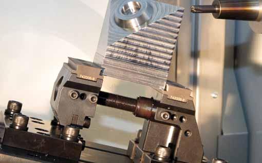
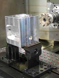
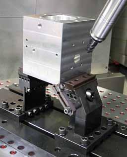
1 Machining and workholding Universal 5 Axis Vise Positive high strength clamping close to the work-piece Obstruction free 5-axis machining


![89 ] (page ) above the table, machining is done in the best possible position for machine tool and work-piece.](/docs-images/83/87275667/images/2-4.jpg "This creates the possibility of working with the shortest and most stable tools.")

2 Obstruction free 5-side machining More and more companies are investing in 5 axis machining centres to enable increasingly challenging requirements for more complex work-pieces, shorter run times and smaller batch sizes to be satisfied. Growing importance therefore attaches to the workholding method for which new solutions must be found. The optimal solution for the following key requirements unrestricted all-around access to the work-piece a optimum above the table high clamping force 3 kn / 77 lb b, secure clamping by grip jaws with pull-down force c low clamping depth c suitability for raw or premachined, cubical, round or odd shaped parts d un-parallel parts are easily clamped e variable clamping range, - > mm (, - > ) minimum weight easy loading flexibility operational from two sides With a clamping depth of just or 8 mm [.57 or.35 ] and a freely selectable of, 5, 5 and 75 mm [3.93,.9, 5.9, 6.89 ] (page ) above the table, machining is done in the best possible position for machine tool and work-piece. This creates the possibility of working with the shortest and most stable tools. Cube, round and odd shaped work-pieces can be clamped to fit their shape easily with the grip jaws (page ) with no need for previous embossing! Additionally pre-machined work-pieces can be clamped accurately using machinable soft jaws (page ) and support-plates (page 3). The clamping range (page ) is limited only by the size of the machine table mm mm 3
.")
 as well as to most T-slot or grid machine tables.")

3 The clamping unit can be mounted directly on T-slot (page 6) or grid machine tables (page 7), grid-plates, pallets or on a base plate (page 5). This base plate includes a number of bores that permit a direct link to the zero point clamping system (vb catalog 7.5) as well as to most T-slot or grid machine tables. The clamping force is generated right below the clamping surface. This completely prevents spreading of the clamping jaws, as can happen if conventional high clamping jaws are used on bed rails with a low mounted spindle. parallel clamping conventional opens under working strain Clamping force no flare out under tension Clamping force 3
 mm (.7 ) ± mm (,787 ) 7- mm (8.66 ) mm (8.66 ) ± mm (,787 ) 7-3 3 mm (.598 ) 3 mm (.")
4 Clamping capacity (3.937 ) 5 Clamping range 7 height / 5 (3.937 /.9 ) (3.937 ) 5 Clamping range Spindle 7 8 height 5 / 75 (5.96 / 6.89 ) Spindle 8 Part no. Spindle length mm Clamping range mm Jaw movement mm 7- mm (.7 ) mm (.7 ) ± mm (,787 ) 7- mm (8.66 ) mm (8.66 ) ± mm (,787 ) mm (.598 ) 3 mm (.598 ) ± mm (,787 ) Clamping of larger parts is easily done by joining or more spindles together with the coupling nut part no. 73. max. tightening clamping force Nm / 8 ft-lb 3 kn / 77 lb Coupling nut part no. 73 Spindle setup Secure spindle nut part no. 78 with set screws part no. 7 SM5x6 on locking slots Spindle nut part. no. 78 Spindle Locking slot Driving sleeve part no. 7, secure with locking screw part no. 7 M6x3 Mount locking nuts part no. 79 with play, secure with locking screw part no. 7 M6x3 Mounting adapter part no. 7 Mounting aid for driving sleeve or locking nut Mounting adapter part no. 7 Mounting aid for driving sleeve or locking nut Locking screw part no. 7 M6x3 Locking slot Locking nuts part no. 79 Locking screw part no. 7 M6x3 minimum thread reach in to driving sleeve Locking screw part no. 7 M6x3 Mounting adapter part no. 7 Mounting aid for driving sleeve or locking nut Mounting adapter part no. 7 Mounting aid for driving sleeve or locking nut fixed jaw side Spindle moving jaw side max. tightening Nm / 8 ft-lb clamping force 3 kn/ 77 lb Torque wrench - Nm part no. Stahlwi gr Ratchet insert / part no. Stahlwi -/ Socket head bit 8 mm part no. Stahlwi 8//
5 Set with T-slot baseplate 5 Sample: 7 Set 3 ( mm / ) x mounting block (Pos. see page ) Art. Nr x mounting block (Pos. see page ) part no x T-slot baseplate (Pos. see page ) part no. 76-T6 x spindle mm (.7 ) (Pos.5 see page ) part no. 7- clamping range - mm x grip jaw 8 mm (,35 ) (Pos. see page ) part no jaws-width mm Vise with mounting blocks fixed jaw side part no moving jaw side part no T-slot baseplate 7...-T6 vb 5 ax - vb 5 ax - 5 vb 5 ax - 5 vb 5 ax - 75 L mm (5.78 ) Part no. 7-T6 L 5 mm (9.685 ) Part no. 75-T6 L 6 mm (3,6 ) Part no. 76-T6 Order no. 7 Set x x 7 Set x x 7 Set 3 x x 7 Set x x 7 Set 5 x x 7 Set 6 x x 7 Set 7 x x 7 Set 8 x x 7 Set 9 x x 7 Set x x 7 Set x x 7 Set x x height /5 L (3.937 ) height 5/75 (5.96 /6.89 ) 5 (9.83 ) (3.937 /.9 ) Accessories see page 8 5
6 Set to fit T-slot machine table 5 Mounting blocks assembly screw Mx5 Ø +, -, 3 shoulder bush Ø Ø +, -, +, -, Pos.3 shoulder bush Ø6 T-nut key way nut Sample: 7 Set 3 ( mm / ) x mounting block (Pos. see page ) part no x mounting block (Pos. see page ) part no x key way nut T8-T (Pos.) * part no x shoulder bush Ø6 -Ø (Pos.3) * part no x screw Mx5 (Pos.) * part no. 7 Mx5 8 x T-nut (Pos.) * part no. 775-PT6- x spindle mm (.7 ) (Pos.5 see page ) part no. 7- clamping range - mm x grip jaw 8 mm (,35 ) (Pos. see page ) part no * matching to machine table (see page 8/9/ or Check list page ) 8 H7 g7 g7 6 g7 8 g7 mounting block Pos. key way nut to fit T-slot T-slot Pos. T-nut jaws-width mm Vise Mounting blocks to fit T-slot machine table (see page ) Pos. (fixed jaw side) Pos. (moving jaw side) vb 5ax - - vb 5ax vb 5ax vb 5ax fixed jaw side Part no moving jaw side Part no fixed jaw side Part no. 7-5 moving jaw side Part no. 7-5 fixed jaw side Part no. 7- moving jaw side Part no. 7- fixed jaw side Art. Nr. 7- moving jaw side Part no. 7- Order no. 7 Set 3 x x x 7 Set 3 x x x 7 Set 3 x x x 7 Set 33 x x x 7 Set 3 x x x 7 Set 35 x x x 7 Set 36 x x x 7 Set 37 x x x 7 Set 38 x x x 7 Set 39 x x x 7 Set x x x 7 Set x x x 7 Set x x x 7 Set 3 x x x 7 Set x x x 7 Set 5 x x x Accessories see page 8 6
7 Set to fit grid machine table 5 Sample: 7 Set / 6.89 mounted to off-center-positiongrid spacing 5 by brackets with torsion plates and damping plate) x mounting block (Pos. see page ) part no. 7-5 x mounting block (Pos. see page ) part no. 7-5 x spindle mm (.7 ) (Pos.5 see page ) part no. 7- clamping range - mm x grip jaw 8 mm (,35 ) (Pos. see page ) part no x bracket to grid 5 Ø6 (Pos.9) part no x shoulder bolt M6 for grid 5 (Pos.3) part no. PT Set / 6.89 mounted to off-center-positiongrid spacing by brackets with torsion plates and damping plate) x mounting block (Pos. see page ) part no. 7- x mounting block (Pos. see page ) part no. 7- x spindle mm (.7 ) (Pos.5 see page ) part no. 7- clamping range - mm x grip jaw 8 mm (,35 ) (Pos. see page ) part no x bracket to grid Ø (Pos.9) part no x shoulder bolt M for grid (Pos.3) part no. 7 M jaws-width mm vb 5ax - vb 5ax - 5 Vises vb 5ax - 5 vb 5ax - 75 Mounting blocks to fit grid, spacing 5 or (see page ) Pos. (fixed jaw side) Pos. (moving jaw side) grid spacing 5 Ø6M6 mounting blocks to fit on off-center-position-grid by brackets part no fixed jaw side part no. 7-5 moving jaw side part no. 7-5 grid spacing ØM mounting blocks to fit on off-center-position-grid by brackets part no. 75- fixed jaw side part no. 7- moving jaw side part no. 7- Order no. 7 Set 5 x x 7 Set 5 x x 7 Set 5 x x 7 Set 53 x x 7 Set 5 x x 7 Set 55 x x 7 Set 56 x x 7 Set 57 x x Accessories see page 8 Blank mounting blocks part no. 7- / 7- to fit on center-position-grid 5 Ø6M6 mounted with brackets part no Blank mounting blocks can be machined to fit any custom size Mounting blocks part no / 7-63 to fit on center-position-grid ØM mounted with brackets part no Set 6 x x 7 Set 6 x x 7 Set 6 x x 7 Set 63 x x 7 Set 6 x x 7 Set 65 x x 7 Set 66 x x 7 Set 67 x x 7
8 Parts list a a 8
9 Pos. Description pcs Part no. mounting block fixed jaw for T-slot mounting block fixed jaw for grid 5 / T-slot 7-5 mounting block fixed jaw for grid / T-slot 8 7- mounting block fixed jaw blank 7- mounting block moving jaw for T-slot mounting block moving jaw for grid 5 / T-slot 7-5 mounting block moving jaw for grid / T-slot 8 7- mounting block moving jaw blank 7- adapter plate for height adapter plate for height adapter plate for height fixed jaw 7 torsion plate for height 77-5 torsion plate for height torsion plate for height torsion plate for height a damping plate for height D damping plate for height D 6 moving jaw 75 7 socket screw M8x5(mounting torsion plate to moving jaw side) 8 7 M8x5 8 socket screw M8x3 (mounting torsion plates to moving jaw side) 8 7 M8x3 shoulder bolt Mx-35 for height 7 M shoulder bolt Mx5-6 for height 5 7 M shoulder bolt Mx7-85 for height 5 7 M-7-85 shoulder bolt Mx95- for height 75 7 M-95- base plate 5xx5 T-slot -6 7-T6 base plate 5x5x5 T-slot T6 base plate 5x6x5 T-slot T6 T-nut M (corresponding to T-slot on table) 775 PT6- T-nut M (corresponding to T-slot on table) 775 PT6- T-nut 6 M (corresponding to T-slot on table) PT6-6 T-nut 8 M6 (corresponding to T-slot on table) 775 PT6-86 T-nut M8 (corresponding to T-slot on table) 775 PT6-8 key way nut T8-T 7-8 key way nut T8-T 7-8 key way nut T8-T key way nut T8-T shoulder bush Ø6 -Ø shoulder bush Ø6 -Ø shoulder bush Ø6 -Ø 7-6 socket screw Mx5 7 Mx5 socket screw Mx5 (standard) 8 7 Mx5 socket screw M6x5 7 M6x5 spindle mm 7-5 spindle mm 7- spindle 3 mm 7-3 Coupling nut 73 Torque wrench - Nm Stahlwi gr Ratchet insert / Stahlwi -/ Socket head bit 8 mm Stahlwi 8// 6 spindle nut 78 7 set screw M5x6 for spindle nut 7 SM5-6 8 locking nut 79 9 driving sleeve 7 socket screw M6x3 7 M6x3 mounting adapter 7- grip jaw 5 mm height 76- grip jaw 8 mm height 76-8 soft jaw 8 mm height 76-R8 soft jaw 3 mm height 76-R3 grip jaw round 5 mm height 76-C grip jaw round 8 mm height 76-C8 3 hexagon socket screw M6x 8 7 M6- spacer to support plate on moving jaw side) 7 support plate for height 7-5 support plate for height support plate for height support plate for height socket screw M8x (mounting support plate to moving jaw side) 7 M8-7 socket screw M8x6 (mounting support plate to fixed jaw side) 7 M8-6 8 socket screw M8x5 (mounting support-plate to moving jaw side fitted with torsion plates) 7 M8-5 9 bracket grid - Ø M 75- bracket grid 5 - Ø6 M a double bracket grid 75-- double bracket grid 5 / shoulder bolt for grid - M M shoulder bolt for grid 5 - M PT Workpiece stop 7 6AWSM 3 Coupling nut 73 9
10 T-slot baseplate Matches all common machine-tool tables and zero point clamping system 6mm (.36 ) 5mm (.77 ) mm (.33 ),mm (.83 ) mm (5.78 ) vb DockLock spacing ±. (7.87 ) x DockLock t plug bores Ø5 (Ø.98 ) 8x for M6 mounting holes H7 (.55 ) 7mm (,63 ) mm (.37 ) mm (3.937 ) 8x for M mounting holes 6 (.96 ) 6mm (,63 ) 5mm (.98 ) 5mm (9.83 ) mm (.575 ) 5mm (.98 ) 5mm (.98 ) mm (.575 ) vb DockLock spacing ±. (7.87 ) Part no. 7-T6 mm (3.937 ) mm (.37 ) Slot for mounting by brackets part no mm (7.87 ) 67mm (6.575 ) 6mm (6.99 ) 5mm (5.96 ) 5mm (.9 ) 5mm (.9 ) 5mm (5.96 ) 6mm (6.99 ) 67mm (6.575 ) 8mm (7.87 ) xmx5/5 xmx.98 /.77 6 (.96 ) 6mm (.36 ) H7 (.55 ) 7mm (,63 ) 6mm (,63 ) 5mm (.77 ) mm (.33 ),mm (.83 ) 5mm (.98 ) 5mm (9.83 ) mm (.37 ) mm (3.937 ) mm (.575 ) 5mm (.98 ) 5mm (.98 ) mm (.575 ) 5mm (9.685 ) vb DockLock spacing ±. (7.87 ) x DockLock t plug bore Ø5 (Ø.98 ) x for M6 mounting holes 8x for M mounting holes vb DockLock spacing ±. (7.87 ) Part no. 75-T6 mm (3.937 ) mm (.37 ) 3mm (9.55 ) 5mm (8.858 ) 8mm (7.87 ) 6mm (6.99 ) 5mm (5.96 ) 5mm (.9 ) 5mm (.9 ) 5mm (5.96 ) 6mm (6.99 ) 8mm (7.87 ) 5mm (8.858 ) 3mm (9.55 ) xmx5/5 xmx.98 /.77 5mm (.77 ) 6mm (3.6 ) x DockLock t plug bore Ø5 (Ø.98 ) 6mm (.36 ) mm (.33 ),mm (.83 ) vb DockLock spacing ±. (7.87 ) 6x for M6 mounting holes 8x for M mounting holes H7 (.55 ) 7mm (,63 ) mm (.37 ) mm (3.937 ) 6 (.96 ) 6mm (,63 ) 5mm (.98 ) 5mm (9.83 ) mm (.575 ) 5mm (.98 ) 5mm (.98 ) mm (.575 ) vb DockLock spacing ±. (7.87 ) Part no. 76-T6 mm (3.937 ) mm (.37 ) 8mm (. ) 5mm (9.83 ) 5mm (8.858 ) 8mm (7.87 ) 6mm (6.99 ) 5mm (5.96 ) 5mm (.9 ) 5mm (.9 ) 5mm (5.96 ) 6mm (6.99 ) 8mm (7.87 ) 5mm (8.858 ) 5mm (9.83 ) 8mm (. ) xmx5/5 xmx.98 /.77
11 Mounting blocks moving jaw side part no. 7-5 moving jaw side part no. 7- (.86") mm (3.937") 75mm (.953") 5mm (.969") 3±, (9.3") 5mm (.969") 75mm (.953") mm (3.937") (.86") 8mm (3.5") 6mm (.36") mm (.575") 88±, (7.") mm (.575") 6mm (.36") 8mm (3.5") bracket grid - Ø M part no. 75-8mm (. ),5mm (.9 ) mm (.39 ) (.87 ) mm (.33") (Ø.63") 5mm (Raster 5) (9.83" grid 5) 5mm (.969") (Ø.63") fixed jaw side part no. 7-5 mm (3.937") (Ø.7") mm (Raster ) (7.87" grid ) mm (.575") (Ø.7") fixed jaw side part no. 7-5mm (5.79 ) mm mm mm (.575 ) (.575 ) (.575 ) (.86") (Ø.63") 5mm (Raster 5) (9.83" grid 5) (Ø.63") (.86") (Ø.7") mm (Raster ) (7.87" grid ) (Ø.7") mm (.575") (.87 ) 35mm (.378 ) 3mm (5.8") 5mm (.969") 5mm (.969") mm (.33") bracket grid 5 - Ø6 M6 / part no mm (3.937") 75mm (.953") 5mm (.969") 3±, (9.3") Use for: Grid 5 center-position / off-center-position T-slot center-position / off-center-position T-slot 5 off-center-position Off-center-position-grid 5 Ø6M6 mounted with brackets (Pos.9) 5mm (.969") 75mm (.953") mm (3.937") 8mm (3.5") 6mm (.36") mm (.575") 88±, (7.") Use for: Grid center-position / off-center-position T-slot 8 center-position / off-center-position T-slot off-center-position Off-center-position-grid ØM mounted with brackets (Pos.9) moving jaw side part no moving jaw side part no. 7- (.86") 63mm (.8") 3,5mm (.") 8±, (5.87") 3,5mm (.") 63mm (.8") 3mm (.8") (.86") 8±, (7.") mm (.575") 6mm (.36") 8mm (3.5") mm (.575") 3mm (5.8") 8mm (7.87 ) 8mm (. ) 5mm (.59 ) 5m m 5m m 5m m (.969 ) (.969 ) (.969 ) 8 8 (.87 ) mm (.39 ) 35mm (.378 ) (.87 ) To mount or more 5ax vises next to each other on a grid / 5 or inch (Ø.7") 6mm (Raster ) (6.99" grid ) (Ø.7") 3mm (.8") 9mm (3.53") (Ø.63") mm (Raster 5) (7.87" grid 5) (Ø.63") double bracket grid part no fixed jaw side part no fixed jaw side part no (.5) (.86") (Ø.7") 6mm (Raster ) (6.99" grid ) (Ø.7") (.86") (Ø.63") mm (Raster 5) (7.87" grid 5) (Ø.63") 35 x 63mm (.8") 3,5mm (.") 8±, (5.87") 7mm (.756") mm (3.937") Use for: T-slot 63 center-position / off-center-position Center-position-grid ØM mounted with brackets (Pos.9) 3,5mm (.") 63mm (.8") 8±, (7.") Use for: Customizing Center-position-grid 5 Ø6M6 mounted with brackets (Pos.9) 3mm (5.8") double bracket grid 5 / part no (.3) (.3) (.3) (.3)
12 Jaws Grip jaw, hardened, 8 mm height part no Grip jaw, hardened, 5 mm height part no. 76- Soft jaw part no. 76-R8 (8 mm in height from support plate) Soft jaw part no. 76-R3 (3 mm in height from support plate) Grip jaw round, hardened, 8 mm height part no. 76-C8 Grip jaw round, hardened, 5 mm height part no. 76-C 8 (,35 ) (,57 ) 7 (,76 ) 8 (,35 ) 5 (,97 ) 3,6 (, ) (3,937 ) (3,937 ) (3,937 ) (3,937 ) 8 (,35 ) (,57 ) 7 (,76 ) 5 (,97 ) (,57 ) 3,6 (, ) (,7 ) 38 (,96 ) ø9 (ø, ) ø9 (ø, ) ø35,8 (ø,9 ) ø35,8 (ø,9 ) Workpiece stop Part no. 7 6AWSM (Pos.3) see page 9 8 (3,5 ) 8/53 (, /,87 ) 56 (,5 )
 Support plate Pos.5 Spacer Pos. Hexagon socket screw M8x Pos.6 Hexagon socket screw M8x6 Pos.7 Support plate Pos.5 Spacer Pos. Hexagon socket screw M8x Pos.6 Hexagon socket screw M8x6 Pos.7 Support plate Pos.5 Spacer Pos. Hexagon socket screw M8x6 Pos.7 Hexagon socket screw M8x5 Pos.")
 Spacer (Pos.) Part no. 7 socket screw M8x (Pos.6) Part no.")
13 Support plates Accurate height clamping of premachined work pieces is performed by using support plates in combination with machinable soft jaws. (,57 ) (3,937 ) Description Height mm / Part no. height / 5 / 5 / 75 ±, mm (3.937 /.9 / 5.96 / 6.89 ) Support plate Pos.5 Spacer Pos. Hexagon socket screw M8x Pos.6 Hexagon socket screw M8x6 Pos.7 Support plate Pos.5 Spacer Pos. Hexagon socket screw M8x Pos.6 Hexagon socket screw M8x6 Pos.7 Support plate Pos.5 Spacer Pos. Hexagon socket screw M8x6 Pos.7 Hexagon socket screw M8x5 Pos.8 Support plate Pos.5 Spacer Pos. Hexagon socket screw M8x6 Pos.7 Hexagon socket screw M8x5 Pos M8x 7 M8x M8x 7 M8x M8x6 7 M8x M8x6 7 M8x5 Soft jaw, part no. 76-R8 or 76-R3 (see page ) Spacer (Pos.) Part no. 7 socket screw M8x (Pos.6) Part no. 7 M8- (with two torsion plates M8x5 Art. Nr. 7 M8x5, Pos. 8) socket screw M8x6 (Pos.7) Part no. 7 M8-6 3
14 Check list for custom dimensions Height above table: Clamping length: T-slot tables T-slot spacing: T-slot width: Thread size: Center-position slot: Off-center-position slot: Grid tables Grid spacing: Grid size / thread size: Mounting fixed and moving jaw side by brackets: Mounting fixed side to grid, moving side by brackets: Center-position-grid: Off-center-position-grid:

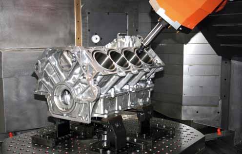
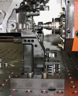
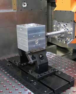
15 Examples of applications 5
16 9. / / LD Copyright Vischer & Bolli AG changes reserved
2014 / Universal 5 Axis Vise Positive high strength clamping close to the work-piece Obstruction free 5-axis machining
 21 / 215 Vischer & Bolli Machining and workholding Universal 5 Axis Vise Positive high strength clamping close to the work-piece Obstruction free 5-axis machining Obstruction free 5-side machining More
5-AXIS MACHINING SCS QUINTUS WWW. WORKHOLDINGSOLUTIONSGROUP. COM
 WORKHOLDING SOLUTIONS FOR -AXIS MACHINING SCS MC QUINTUS ONE system / MANY solutions WWW. WORKHOLDINGSOLUTIONSGROUP. COM MCCLAMPING S YSTEM for -axis machining MC + Quintus... MC Clamping System Free access
5-axis clamping system compact
 5-axis clamping system compact 395 5-axis clamping system compact Function We are setting standards with the new KIPP 5-axis clamping system compact in this field. The system was specifically designed
5-Axis Machine Tools from SMW-AUTOBLOK
 5-Axis Machine Tools from SMW-AUTOBLOK 5-Axis Machine Tools ensures the following advantages: Ideal suitable for OP 10 use ST5-2G also suitable for OP 20 use Jaws with SinterGrip clamping inserts for clamping
adaptivemechanical adaptive
 Mechanical clamping elements mechanical 6 Content Product group 6 Sliding clamp, mechanical 6.2210 Clamping block, mechanical 6.2212 High-pressure spindle, mechanical with integral wedge system 6.2270
5-Axis Machine Tools from SMW-AUTOBLOK
 -Axis Machine Tools from SMW-AUTOBLOK -Axis Machine Tools ensures the following advantages: Ideal suitable for OP 10 use Jaws with SinterGrip clamping inserts for clamping of workpieces with lowest depth
IDEAL FOR 5-AXIS MACHINING
 IDEAL FOR 5-AXIS MACHINING Without additional foundations or special jaws, the RZM centric vice holds the workpiece securely and does this with a minimal interference contour. The clamping spindle is located
Zero Point Clamping System. ZERO lock BALL lock
 Zero Point Clamping System ZERO lock BALL lock kap3 kap 263 Technical information regarding ZERO lock Zero Point Clamping System Application The modularly designed, flexible ZERO lock Zero-Point Clamping
Clamping devices 521
 Clamping devices 521 522 Product overview Clamping devices Adjustable straps K0001 Hook clamps K0012 Goose-neck straps with long slot K0002 Page 526 Hook Clamps with collar K0013 Page 535 Equipped clamps
IDEAL FOR 5-AXIS MACHINING
 IDEAL FOR 5-AXIS MACHINING Without additional foundations or special jaws, the RZM centric vice holds the workpiece securely and does this with a minimal interference contour. The clamping spindle is located
O-Sullivan King 4 Poster Bed O-Sullivan Queen 4 Poster Bed Parts and Hardware List
 Parts and Hardware List A. Left Headboard Post 1 pc B. Right Headboard Post 1 pc C. Left Footboard Post 1 pc D. Right Footboard Post 1 pc E. Headboard Panel 1 pc F. Footboard Rail 1 pc. Spindles 4 pcs
OPERATING INSTRUCTIONS 5-AXIS CLAMPING SYSTEM + ACCESSORIES
 OPERATING INSTRUCTIONS 5-AXIS CLAMPING SYSTEM + ACCESSORIES 1 Contents 1. Introduction 2. Safety instructions and precautions 3 Operating the clamp 3.1 Clamp set up 3.2 Sequence for clamp set up 3.3 Adjusting
Clamping devices - mechanical
 Zero point reference also on down draw clamps A fixed zero point reference on down draw clamps is self-evident in the STARK zero point mounting system. This zero point reference on down draw clamps is
INCREASE YOUR MACHINE UPTIME!
 INCREASE YOUR MACHINE UPTIME! QUICK CHANGEOVER The right machine, processes, tooling and workholding reducing the in between time is a key factor! Jergens Ball Lock Mounting system is the original quick-change
MC-CVR-1. Király Trading KFT H-1151 Budapest Mogyoród útja
 MC-CVR-1 Király Trading KFT H-11 Budapest Mogyoród útja -14 E-mail:_agi@kiralytrading.hu carver clamp Series Applications C-Style Carver Clamps A djustment screw is shielded and out of the work area Ideal
NEW RÖHM VICE NOVELTIES. RKE-M and RZM (size 92)
") NEW RÖHM VICE NOVELTIES RKE-M and RZM (size 92) NC-COMPACT-VICE RKE-M MANUALLY OPERATED APPLICATION Particularly suitable for use on machining centers and palletisers. TYPE Clamping system mechanical without
NEW RÖHM VICE NOVELTIES RKE-M and RZM (size 92) NC-COMPACT-VICE RKE-M MANUALLY OPERATED APPLICATION Particularly suitable for use on machining centers and palletisers. TYPE Clamping system mechanical without
LOW PROFILE CLAMPING. Jergens OK-Vise. Micro Clamps
 Jergens OK-Vise Serrated and Smooth Jaws...296 Machinable Jaw... 297 Mounting Jaw... 298 Self-Adjustable...299 Pull-Down... 300 301 Economy... 302 Low Profile Comparison Chart... 303 Multi-Rail RM System...
Clamping bolts Eccentrical cams clamping units
 2.3 Shaft Clamping bolts Eccentrical cams clamping units 2.9 2.8 2.7 2.6 2.5 2.4 2.3 2.2 2.1 2.3 Clamping bolts, Eccentrical cams, Shaft clamping units Page 641 2.3 Clamping bolts, Eccentrical cams, Shaft
50, ,000 18,800 8,000. CODE 04 ER (ER ) UPC Chuck/W ITS Central Chuck. CODE 04 ER (ER ) UPC Pallet For Alignment
 UPC Chuck/W ITS Central Chuck. CODE 04 ER (ER ) UPC Pallet For Alignment") CODE 04 ER-007826 (ER-017777) UPC Pallet For Alignment CODE 04 ER-007823 (ER-016092) UPC Chuck/W ITS Central Chuck Application To align angular position and to determine the center of UPC chucks. Please
CODE 04 ER-007826 (ER-017777) UPC Pallet For Alignment CODE 04 ER-007823 (ER-016092) UPC Chuck/W ITS Central Chuck Application To align angular position and to determine the center of UPC chucks. Please
Technical features. Positive Taper Lock System for manual tool clamping. Technical features:
 clamping set Technical features The RÖHM- was specially designed for the positive taper lock clamping taking particulary into account the necessity of manual clamping. Technical features: strong design
STEVENS SUBPLATES. STEVENS ENGINEERING, INC. TOLL-FREE WEB FAX
 STEVENS SUBPLATES Spacing of hole patterns on Stevens accessories is identical to the pattern on Stevens Subplates. Insertion of the pull dowels thru bushed holes in the accessory into corresponding bushed
STAMPING TECHNOLOGY - CLAMPING RAW PARTS
 simple. gripping. future. 5-Axis 66 Makro Grip Stamping Unit 72 Stamping Unit for the workbench 73 Stamping Unit on trolley 76 Stamping Unit Accessories 77 Stamping Jaws 78 Makro Grip 5-Axis-Vices 82 5-Axis
PRODUCTION VISES. Vises. Bock Quick Change Fixturing. 5-Axis Production Vises
 Vises Introduction to Design... 74 75 VMC/HMC Solutions...76 77 Ball Lock Mounting System...78 79 Production Vises 4" (100 mm) Production Vises... 80 81 6" (150 mm) Production Vises...82 83 Self Centering
Reference systems for electrode manufacturing & EDMing
 Reference systems for electrode manufacturing & EDMing Conventional setting-up Machining time Idle time One manned shift eight hours Pallet system Job 1 Job 2 Job 3 Job 4 Job 5 Job 6 Job 1 Job 2 Job 3
Page 1. SureMotion Quick-Start Guide: LARSACC_QS 1st Edition - Revision A 03/15/16. Standard Steel Bolt/Screw Torque Specifications
 R K C T I Repair Kit Product Compatibility Repair Kit # Linear Actuator Assembly # LARSACC-013 LARSACC-014 LARSD2-08T12BP2C (12-in travel) LARSD2-08T24BP2C (24-in travel) C P I R K 1 ea Ball Screw with
Pull-down clamps. No Low height clamping jaws, model Bulle
 Pull-down clamps The wedge action of clamping jaws is the characteristic feature of these pull down clamps. It causes the pull down effect, which presses the workpiece against both, stop and machine table.
Jaw chuck B-Top3 STANDARD CHUCKS. 215 Variant. Jaw chuck B-Top3. Technical data. Size. B-Top3
 STANDARD CHUCKS. Technical data A AJ DH AI AT AW T BQ AS Size 215 ariant B-Top3 Concentricity [mm] Max. clamping force [kn] Max. axial drawtube force [kn] RPM n max. [1/min.] Stroke per jaw [mm] Ø Capacity
TWL 1500 TORQUE WRENCH LOADER
 TWL 1500 TORQUE WRENCH LOADER OPERATOR S HANDBOOK (PART NUMBER 60246.1) CONTENTS PAGE 1 OF 8 INTRODUCTION 2 SPECIFICATION 3 ITEMS SUPPLIED 3 AVAILABLE OPTIONS 3 ASSEMBLY INSTRUCTIONS A. ASSEMBLY OF TRANSDUCER
TECHNICAL INFORMATION Models No.
 TECHNICAL INFORMATION Models. Description 6207D, 6217D, 6237D,, 9.6V, 12V, 14.4V Cordless Driver Drills 10mm (3/8") 12V, 14.4V, 18V Cordless Driver Drills 13mm (1/2") CONCEPT AND MAIN APPLICATIONS These
CAM SYSTEM. Eccentric self-locking clamping devices. Set. CAM SYSTEM t. CAM SYSTEM t. Set. CAM SYSTEM s pag CAM SYSTEM s pag.
 Eccentric self-locking CAM SYSEM Set CAM SYSEM t pag. 12 CAM SYSEM t pag. 126 Set CAM SYSEM s pag. 127 CAM SYSEM s pag. 128 EDGE CLAMP pag. 130 123 CAM-SYSEM eccentric self-locking he CAM SYSEM has been
GF Machining Solutions. System 3R. Mecatool WEDM. Productportfolio. Version 2, valid from July 1st. 2017
 GF Machining Solutions System 3R Mecatool WEDM Productportfolio Version 2, valid from July 1st. 2017 Design and quality by System 3R Contents Zeroline...page ICS...page 7 Unimatic...page 15 Accessories...page
IN 578. Tools Required. Torque Specification: 10mm Socket 7/16 Socket 1/2 Socket 1/2 Wrench 7/16 Wrench 1/8 Allen Wrench.
 Tools Required 2011-C Ford F250/F350 No Drilling into Vehicle is Required 10mm Socket 7/16 Socket 1/2 Socket 1/2 Wrench 7/16 Wrench 1/8 Allen Wrench FL277 x 1 Torque Specification: 1/4 Bolts - 6 Ft Lbs.
Continuum Frame Assembly Instructions
 Continuum Frame Assembly Instructions Copyright January 1, 2017 Jim M. Bagley, GraceWood, Inc (Reproduction Prohibited) Version 2.2 Table of Contents Continuum Frame Table of Contents... i Warranty...ii
PRS Retro Z-Axis Installation
 PRS Retro Z-Axis Installation Page -1- PRS Retro Z-Axis Installation This document is a guide to installing the PRS Retro Z-axis on early ShopBot models. It describes installation for PR models with PK299
Diesel Pile Hammer D30-32 Part # 66508
 Diesel Pile Hammer D30-32 Part # 66508 2 Diesel Pile Hammer D30-32 Part # 66508 Pos Order No Pg Description Qty 66508 Diesel Pile Hammer D30-32 cmpl 1 1 108742 4 Cylinder Lower Part cmpl 1 2 60151 Inner
VISES, BASES, PALLETS & TOMBSTONES AXIS WORKHOLDING]
![VISES, BASES, PALLETS & TOMBSTONES AXIS WORKHOLDING]](/thumbs/73/69262991.jpg "VISES, BASES, PALLETS & TOMBSTONES AXIS WORKHOLDING]") [ 5,, PLL & OMON OROLN] MaxLock P40, P440, & P460 ises vailable with errated, ovetail (), or arvable [] jaws. errated and ovetail jaws have different clamping areas, at the bed, in the middle of the jaw
[ 5,, PLL & OMON OROLN] MaxLock P40, P440, & P460 ises vailable with errated, ovetail (), or arvable [] jaws. errated and ovetail jaws have different clamping areas, at the bed, in the middle of the jaw
VISES VISES JAWS CENTERING CLAMP BASE PLATE COMPACT PNEUMATIC VISE PAIR OF CLAMPS PAIR OF POSITIONING KEYS PAIR OF POSITIONING KEYS VISES
 CENTERING CLAMP JAWS BASE PLATE Part No. CP170 Part No. CP175 Part No. CP179 COMPACT PNEUMATIC VISE Part No. AMLFV-S PAIR OF CLAMPS Part No. MVAC-CS PAIR OF POSITIONING KEYS Part No. MVAC-SK PAIR OF POSITIONING
Lathe Accessories. Work-holding, -supporting, and driving devices
 46-1 Lathe Accessories Divided into two categories Work-holding, -supporting, and driving devices Lathe centers, chucks, faceplates Mandrels, steady and follower rests Lathe dogs, drive plates Cutting-tool-holding
Diesel Hammer Model D19-42 Part #
 Diesel Hammer Model D19-42 Part # 120491 2 Diesel Pile Hammer Part # 120941 Pos Order No. Pg Description Qty 120941 Diesel Pile Hammer D19-42 (Bauer MNR:426514) 1 160198 4 Cylinder Lower Part cmpl 1 2
Flat Panel Stand FPZ-655. for 32" to 55" Flat Panel Screens FEATURES. Reinforced universal adapter plate for a strong hold
 FPZ-655 Flat Panel Stand for 32" to 55" Flat Panel Screens For a viewing experience that really stands out, Peerless FPZ-655 Universal Flat Panel Stand for 32" 55" flat panel TVs provides a brilliant combination
PUSH-PULL-PROPS. and accessories ROBUSTA-GAUKEL GMBH MOUNTING TECHNOLOGY &CO.KG
 PUSH-PULL-PROPS and accessories MOUNTING TECHNOLOGY ROBUSTA-GAUKEL GMBH &CO.KG MOUNTING TECHNOLOGY PUSH-PULL-PROPS AND ACCESSORIES INDEX General information...................... 3 Push-pull-prop Type
TITAN2-EDGE Public Access Computer Station Dual Track
 TITAN2-EDGE Public Access Computer Station Dual Track TITAN2-EDGE Rev A 6/17 Model TITAN2-EDGE ASSEMBLY AND ADJUSTMENT TITAN2-EDGE PARTS AND TOOLS PLEASE REVIEW these instructions before beginning the
WM / Zero point mounting system SPEEDY metec
 WM-020-294 / 04.2008 Zero point mounting system SPEEDY metec 2 Informations SPEEDY metec 1 / 2 / 3 Content and overview of order no. SPEEDY metec 1 Page Order no. SPEEDY metec 1 4 2000 001 Insertion nipple
ASSEMBLY OF THE KNOCKED-DOWN LADDERS: 8 to 12 STEPS STANDARD TOP AND SAFELOCK REQUIRED TOOLS
 ASSEMBLY OF THE KNOCKED-DOWN LADDERS: 8 to 12 STEPS STANDARD TOP AND SAFELOCK REQUIRED TOOLS SAFETY GLASSES 7/16" WRENCH OR SOCKET STEP LADDER OF APPROPRIATE HEIGHT (2) 9/16" WRENCHES OR SOCKETS RUBBER
INSTALLATION INSTRUCTIONS UTV LIGHT BAR KIT Part Number: and Application: All UTV s*
 INSTALLATION INSTRUCTIONS UTV LIGHT BAR KIT Part Number: 83970 and 84360 Application: All UTV s* * does not include Arctic Cat vehicles Your safety, and the safety of others, is very important. To help
PZS. Precision vices. Precision vices PZS
 Simple clamping and releasing with the inner hexagon key. Type 735-60 PL-S micro with quick adjustment Item no. Size Squareness Parallelism Jaw G H J Work locator 1179514 1 0,005 0,002 34 25 15 75 20 20
MACHINE TOOL ACCESSORIES
 VERTICAL 5-C COLLET VISE SERIES 344: VERTICAL 3-C COLLET VISE SERIES 344: : 2-1/2 x 7-3/4 Height: 4 Small movement of lever opens or closes collet. 2030000 CAM OPERATED 5-C HORIZONTAL/VERTICAL COLLET FIXTURE
BX1956 Installation Instructions Chrysler PT Cruiser (Include Turbo)
") BX1956 Installation Instructions 2001-04 Chrysler PT Cruiser (Include Turbo) Serial No. The front fascia and metal bumper are removed for baseplate installation. Factory metal bumper will not be reinstalled.
BX1956 Installation Instructions 2001-04 Chrysler PT Cruiser (Include Turbo) Serial No. The front fascia and metal bumper are removed for baseplate installation. Factory metal bumper will not be reinstalled.
Alufix Basic Sets offer a variety of application possibilities based on the quantity of components (from 19 to over 440) and their composition
 and their composition") ALUFIX BASIC SETS 2 ALUFIX BASIC-SETS Alufix Basic Sets offer a variety of application possibilities based on the quantity of components (from 19 to over 440) and their composition ALUFIX BASIC-SETS Note:
ALUFIX BASIC SETS 2 ALUFIX BASIC-SETS Alufix Basic Sets offer a variety of application possibilities based on the quantity of components (from 19 to over 440) and their composition ALUFIX BASIC-SETS Note:
Dimensions of the machine spindle heads in accordance with DIN The latest issue of the DIN sheet is binding
 Info Dimensions of the machine spindle heads in accordance with DIN The latest issue of the DIN sheet is binding DIN 55026 from taper size 4 with driver. Spindle head Size C1 C2 D hole count outer olt
HONDA RIDGELINE (KIT #601) Installation Instructions (to be used in addition to owners manual)
 Installation Instructions (to be used in addition to owners manual)") HONDA RIDGELINE (KIT #601) Installation Instructions (to be used in addition to owners manual) IMPORTANT NOTE: Read before beginning installation. These instructions replace all of Step 1 of the instructions
HONDA RIDGELINE (KIT #601) Installation Instructions (to be used in addition to owners manual) IMPORTANT NOTE: Read before beginning installation. These instructions replace all of Step 1 of the instructions
CTTR Tire Rack Required tools
 CTTR Tire Rack Required tools Torque wrench, ratchet, 9/16 socket, tape measure, and square edge. ASSEMBLY REQUIREMENTS *Torque all T-bolt nuts to 35-40 foot pounds. Failure to follow the assembly instructions
SPARE PARTS LIST MODEL NO. LB1200F PAGE 1 ITEM PART NO. DESCRIPTION QTY NOTE
 PAGE 1 001 JM21000018 HEX.SOCKET HEAD SCREW M5X12 4 002 JM21000019 SPRING WASHER 5 4 003 JM21000020 FLAT WASHER 5 4 004 JM21000021 UP COVER COMPLETE 1 005 JM21000025 MICRO SWITCH FIX PANEL A 1 006 JM21000026
Modular clamping and positioning system for milling machines and machine tool. flexible
 Modular clamping and positioning system for milling machines and machine tool flexible Titan 125 Everything under control The new Allmatic TITAN 125 high pressure vice combines virtually all the features
Side-of-Pole Mount for 4 Modules (SPM4) For Module Type B ASSEMBLY INSTRUCTIONS. step-by-step assembly and installation
 For Module Type B ASSEMBLY INSTRUCTIONS. step-by-step assembly and installation") Side-of-Pole Mount for 4 Modules (SPM4) For Module Type B ASSEMBLY INSTRUCTIONS step-by-step assembly and installation Version 1, Rev A SP3358-2 PCN 060712-5 Side-of-Pole Mount for 4 Modules (SPM4) For
Side-of-Pole Mount for 4 Modules (SPM4) For Module Type B ASSEMBLY INSTRUCTIONS step-by-step assembly and installation Version 1, Rev A SP3358-2 PCN 060712-5 Side-of-Pole Mount for 4 Modules (SPM4) For
Assembly, Installation, Operation and Maintenance Instructions Kit, Base Rail Bracket Part # 31852
 . Assembly, Installation, Operation and Maintenance Instructions Kit, Base Rail Bracket Part # 31852 Dealer / Installer: Provide a copy of these instructions to the end user of this product. These instructions
INSTALLATION INSTRUCTION RRU DOUBLE LIGHT POLE MOUNT
 INSTALLATION INSTRUCTION RRU Double Light Pole Mount for installation of two RRU units on mast, towers or other vertical structures. CUE DEE YOUR INNOVATIVE PARTNER 1 CONTENTS 1. PRODUCT COVERED IN THIS
5-AXIS CLAMPING SYSTEM + ACCESSORIES
 5-AXIS CLAMPING SYSTEM + ACCESSORIES CONTENTS Visual Directory P. 10 Jaw Vices P. 11 27 GERMANY norelem Normelemente KG Volmarstraße 1 71706 Markgröningen Tel. +49 7145 206-41 Fax. +49 7145 206-66 info@norelem.de
DO35 MAINTENANCE INSTRUCTIONS
 CUSTOMER INFORMATION SHEET NO. 038 DO35 MAINTENANCE INSTRUCTIONS (DO35 V3 LAUNCHED PRODUCTION JUNE 2017) Table of Contents 1.0 Replacing Spindle Bushes V3... 22 2.0 Replacing Locking Mechanism V3... 6
Tables it will work with
 What does it do? The Self Centering Vise is used to clamp and hold items that are normally to difficult to hold with a standard table clamp or double-sided engraving tape. It can be used to hold notary
BX2173 Installation Instructions Ford Focus (including the 2.3L engine) 2003 Ford Focus SVT
 2003 Ford Focus SVT") BX2173 Installation Instructions 2000-04 Ford Focus (including the 2.3L engine) 2003 Ford Focus SVT Serial No. The front fascia, coolant line bracket and anti-pollution devices are removed for baseplate
BX2173 Installation Instructions 2000-04 Ford Focus (including the 2.3L engine) 2003 Ford Focus SVT Serial No. The front fascia, coolant line bracket and anti-pollution devices are removed for baseplate
Product Information Packet
 Product Information Packet Multi-Lok 6 Inch 4 Sided: March 3, 00 When the E Series product line was introduced, it was a best-in-industry choice for workholding. Over the years, Chick has built on that
WARNING Kia Spectra 5 Installation Instructions BX2713. Serial Number
 Please read BOTH these and the General Instructions before attempting to install or operate this equipment. 1. Blue Ox towing products and accessories are intended to be installed by Blue Ox Dealers who
Save Set-up Time... and More!
 System Bock Save Set-up Time... and More! Bock Locator Plates The foundation for quick change workholding efficiency. The Bock Locator Plate is a hard coated aluminium subplate with precision bored and
Narrow Rail Vise Attachment USERS MANUAL
 Narrow Rail Vise Attachment USERS MANUAL 2006 Chief Automotive Technologies, Inc. Chief s Limited One-Year Warranty & Liability CHIEF'S LIMITED ONE-YEAR WARRANTY & LIABILITY Chief Automotive Technologies,
Instructions & Parts SM100B SM400 K025S1 K005
 Instructions & Parts SM100B SM400 K025S1 K005 Table of Contents 2 SM100B/SM400 Manual Engraver Machine Diagram Pantograph Operation Setup & Layout Engraving & Changing Cutters Adjusting Depth of Cut &
Machine vices RB and RH
 Overview Machine vices RB and RH For high clamping accuracy Special technical features of the RÖHM Machine vices RB and RH: Steel body with stationary jaw, drop forged or body made from spherical graphite
The Phoenix. Professional Quilting Frame. Copyright January 1, 2016 Jim M. Bagley, GraceWood, Inc (Reproduction Prohibited) Version 2.
 Version 2.") The Phoenix Professional Quilting Frame Copyright January 1, 2016 Jim M. Bagley, GraceWood, Inc (Reproduction Prohibited) Version 2.1 1 The Phoenix Professional Quilting Frame Parts List Box 1...3 Box
The Phoenix Professional Quilting Frame Copyright January 1, 2016 Jim M. Bagley, GraceWood, Inc (Reproduction Prohibited) Version 2.1 1 The Phoenix Professional Quilting Frame Parts List Box 1...3 Box
w w w. h d o n l i n e s h o p. d e AUTOMATIC COMPRESSION RELEASE TOOL GENERAL INSTALLATION -J04654 REV Kit Number Models
 -J05 REV. 008-0- GENERAL Kit Number 98-08 Models AUTOMATIC COMPRESSION RELEASE TOOL For model fitment information, see the P&A Retail Catalog or the Parts and Accessories section of www.harley-davidson.com
InTurn TAIL STOCK II
 Specifications for the InTurn TAIL STOCK II accessory for the InTurn Indexing Turning 4 th axis The InTurn series is the only CNC mill accessory that provides both Indexing and coordinated 4 axis motion
NUMBER: S.M. REF.: Listed in Table ENGINE: Series 50/50G DATE: October 2013 SUBJECT: MACHINING CYLINDER BLOCK COUNTERBORES
 NUMBER: 10 25 13 S.M. REF.: Listed in Table ENGINE: Series 50/50G DATE: October 2013 SUBJECT: MACHINING CYLINDER BLOCK COUNTERBORES ADDITIONS, REVISIONS, OR UPDATES Publication Number Platform Section
5 ht Rocklock TM Metric
 Rocklock TM Metric Medium or Large Vise Top Tooling with Adapter All 5th Axis RockLock fixtures utilize industry standard pull stud spacing ensuring compatibility with Jergens, Lang, and other systems
Medium HoneyBadger Chase Rack Installation Instructions
 PREPARATION Medium HoneyBadger Chase Rack Installation Instructions 1. Disconnect the negative terminal on the battery. Park the vehicle on level ground and set the emergency brake. 2. We recommend reading
. Dimensions of the Machine Spindle Heads in Compliance with DIN The most recent editions of the DIN standards are binding.
 Clamping technology. Dimensions of the Machine Spindle Heads in Compliance with DIN The most recent editions of the DIN standards are binding. DIN 55026 Taper sizes 4 and above with drive tang. Spindle
6.1. PUSH-PULL-PROPS and accessories
 6 6.1. PUSH-PULL-PROPS and accessories MOUNTING TECHNOLOGY 6 GENERAL INFORMATION PUSH-PULL-PROPS AND ACCESSORIES INDEX General information....................... 3 Push-pull-props Type R.....................
PRODUC TION VISES. Vises. 5-Axis Production Vises
 Introduction to Design...104 105 VMC/HMC Solutions...106 107 Ball Lock Mounting System...108 109 Production Vises 4" (100 mm) Production Vises...110 112 6" (150 mm) Production Vises...113 115 Short 6"
Installation Instruction
 Tools Needed for Assembly Stud finder (for wood stud wall) Pencil Mark Electric drill Wood Stud Wall Installation Step 1. Locate the Wood Studs Installation Instruction Drill bit (for wood stud wall) Masonry
r e w o e P m xtre r e o F
 For extreme Power 1 2 The origin of the product The Piranhaclamp-system was invented in Switzerland in 2012 by 2 bright engineers. The system was designed for automated machines in 5-axis machining. A
The Only Original Wedge-clamp
 The Only Original Wedge-clamp Small in Size iant in Performance 1 COMPNY PROFILE Founded in 1984, Oy is located in the beautiful lake district of Central Finland, in the Muurame usiness Park, a center
Model: SCD430 SCD640. Installation & Operation Guide P/N SCD640-95
 Model: SCD430 SCD640 Installation & Operation Guide P/N SCD640-95 Model SCD430 and SCD640 Kurt has two Self-Centering vises, a four-inch jaw width (SCD430) and a six-inch jaw width (SCD640). Jaw opening
USSC LLC 4 ONE LLC FIELD MODIFICATION INSTRUCTIONS
 1 OF 17 A 1. PURPOSE: Instructions for in field replacement of 9004 mechanical suspension top pan 2. SCOPE: 9004 mechanical suspension with legacy two point LX back frame and current LX back frame 3. PROCEDURE:
M2 Assembly. M2 Sub-Assemblies mm Belt Sub-Assembly mm Belt Sub-Assembly Spider Sub-Assembly... 4
 M2 Assembly Table of Contents M2 Sub-Assemblies... 3 630mm Belt Sub-Assembly... 3 702mm Belt Sub-Assembly... 3 Spider Sub-Assembly... 4 Idler Bolt Sub-Assembly... 8 Y Motor Sub-Assembly... 9 X Motor Sub-Assembly...
Removing the Z-Axis lead screw
 Page 1 of 8 TITLE: Sabre Z-Axis Lead Screw Replacement Procedure Gerber FastFact #: 5048 Supplied by: Gerber Hardware Support Last Modified: June 14, 2007 Summary: Tools used: The following procedure explains
BX2520 Installation Instructions 2004 Mazda 3
 BX2520 Installation Instructions 2004 Mazda 3 Serial No. The headlight assembly, front fascia, horn bracket and windshield washer reservoir are removed for baseplate installation. Drilling is required.
ZeroClamp. machine tool components
 ZeroClamp machine tool components Even at a low $80 dollar hourly rate, every minute the spindle isn t turning is costing you more than $1 dollar... The tailor-made solution How do you increase machine
ELECTRIC TOOL PARTS LIST
 Hitachi Power Tools LIST E936 ELECTRIC TOOL PARTS LIST COMPOUND SAW Model 2004 4 20 (E1) 1 2 3 23 24 7 8 9 10 6 5 4 15 11 16 12 13 12 14 18 25 26 27 28 29 30 19 17 1 9 11 16 21 624 20 22 39 40 41 42 35
CORKSPORT License Plate Relocation Kit
 I N S T A L L A T I O N I N S T R U C T I O N S CORKSPORT License Plate Relocation Kit 2018+ Mazda 6 PART #: ATK-8-010-10 Need Help With Your Installation? Call (360) 260-CORK PAGE 1 CORKSPORT License
Retro Fit Gearbox Mount. Assembly Instructions. Assembly Instructions. Before You Start. General Information. Manual No M
 Retro Fit Gearbox Mount Assembly Instructions Treker 4400NT & 4400ST Series Before You Start Assembly Instructions Manual No. 700-372M! When you see this symbol, the subsequent instructions and warnings
BMW R1100/R1150GS Instructions for Mounting Medium or Large Pack Rack and Micatech Top Case with Mount Kit
 BMW R1100/R1150GS Instructions for Mounting Medium or Large Pack Rack and Micatech Top Case with Mount Kit Thank you for purchasing the Micatech Pack Rack and Top Case, with R1100/1150GS mount kit. Please
NEWS Part. N /0 MINITEC NEWS
 NEWS 2009 Part. N 95.0423/0 MINITEC NEWS 2009 1 TABLE OF CONTENT INTRODUCTION CONTENTS 3 END CAP Z WITH HAMMER TAPS 3 END CAP 45X45 VA 4 ANGLE 25 GD-Z 4 ANGLE 45X90 GD-Z 5 ANGLE 90 GD-Z 5 HINGE 19 S 6
BX Toyota Tacoma (Includes Prerunner) Installation Instructions
 Installation Instructions") Attachment Tab Height: 11.5 Attachment Tab Width: 30.5" Serial Number Please read BOTH these and the General Instructions prior to installing or operating this equipment. 1. Blue Ox towing products and
Attachment Tab Height: 11.5 Attachment Tab Width: 30.5" Serial Number Please read BOTH these and the General Instructions prior to installing or operating this equipment. 1. Blue Ox towing products and
Self-Centering Vise. Owner s Manual. Operating Instructions. Care & Maintenance. Warranty Information
 Self-Centering Vise Owner s Manual Operating Instructions Care & Maintenance Warranty Information Recommended Torque Specifications V00 Maximum Torque for Vise Assembly: ft lbs (.0 Nm) Maximum Torque for
WORKHOLDING MADE IN EUROPE MANUAL LATHE CHUCKS, CENTERS, ROTATING BODIES OIL COUNTRY CHUCKS, POWER CHUCKS, VTL CHUCKS, ROTARY TABLE PACKAGES
 EUROPEAN PRECISION & QUALITY WORKHOLDING MADE IN EUROPE MANUAL LATHE CHUCKS, CENTERS, ROTATING BODIES OIL COUNTRY CHUCKS, POWER CHUCKS, VTL CHUCKS, ROTARY TABLE PACKAGES EUROPEAN PRECISION & QUALITY With
Double Locating Fixed Vise w/.500 locating holes. Adjustable Vise w/.500 locating holes
 VISES VISES EZE-VISE TM MODULAR SETUPS Low profile, low cost modular vise set incorporates features found in higher priced products: positive location in 3-axes, raised locator surface to facilitate drilling
BuildPro Welding Tables
 Introducing the new BuildPro Welding Tables The affordable, professional BuildPro Welding Tables are setting a new standard in price and performance. Plates can be reconfigured to extend the width of the
Ensat driving tools...
 nsat driving tools... On this page, you can configure the optimum tool for your application. A configuration is provided in the following as an illustrative example. The article number is composed of two
Air Cooled Engine Technology. Roth 9 th Ch 2 Tools & Measuring Pages 21 43
 Roth 9 th Ch 2 Tools & Measuring Pages 21 43 1. A combination wrench has one end and one end. Box & Open Square & Round Ratcheting & Gear 2. A or flare nut wrench is used on metal tubing connection fittings.
SPINDLE ADAPTER SELECTION GUIDE
 CHUCK JAWS RETENTION KNOS SPINDLE ADAPTER SELECTION GUIDE DETERMINING SPINDLE TYPE & SIZE Type A1 and A2 s with A2 mounts can be installed on either A1 or A2 spindle nose. Camlock Type D1 Nose Type A1
Quick-Release Front Vise 05G34.01
 Quick-Release Front Vise 05G34.01 Patent Pending Introduction A front vise is the most generally useful vise on a typical workbench. It can be used for clamping parts on edge within the jaws, for clamping
AX1001. Smith/Functional training Combo-free weight ASSEMBLY INSTRUCTIONS
 AX1001 Smith/Functional training Combo-free weight ASSEMBLY INSTRUCTIONS EXPLODED DIAGRAM 83 84 84 85/86 87 87 88 89 90 91 62 64 64 64 64 64 64 65 65 65 65 66 66 65 66 66 65 63 63 66 67 68 55 66 66 70