C O N T E N T S 01 BILL OF MATERIAL 02 REQUIRED TOOLS 03 ASSEMBLY PROCESS
|
|
|
- Prosper Bond
- 5 years ago
- Views:
Transcription
1 C O N T E N T S 01 BILL OF MATERIAL 02 REQUIRED TOOLS 03 ASSEMBLY PROCESS
2 BILL OF MATERIAL SECTION 01
3 QUANTITY PART DESCRIPTION 1 Bottom plate (3mm Matte CF) 2 Roll bar plate (1.5mm Matte CF) 1 Front arm brace (2.5mm Matte CF) 1 Front standoff - 19mm (Black 3D Printed Plastic) 1 Rear standoff - 19mm (Black 3D Printed Plastic) 2 Washer (M2.5 Steel) 2 Nylock nut (M2.5 Steel) 2 Socket head screw (M2.5 Silver Aluminum) 2 Antenna tube (Black Plastic) 16 M2 washer (Steel) 1 Phillips head screw (#1 x 1/4" Long Steel) 4 Phillips head (#2 x 1/4 Long Steel) 2 Socket head screw (M2 X 4mm Steel) 8 Socket head screw (M2 X 8mm Steel) 12 Socket head screw (M2 X 6mm Steel) 1 Small Velcro Lipo Strap Catalyst Machineworks 1 Huge Ego
4 REQUIRED TOOLS SECTION 02
5 QUANTITY TOOL DESCRIPTION 1 1.5mm allen driver or allen wrench 1 2mm allen driver or allen wrench 1 socket driver(s) 1 Small phillips head screw driver 1 Needle Nose Pliers 3 Adult beverage of choice or apple juice if you are under 21

6 ASSEMBLY PROCESS SECTION 3
7 STEP 1 Parts Required: Quantity Part Description 4 Micro Motor (sold separately) 12 Socket head screw (M2 X 6mm Steel) 12 M2 washer (Steel) *as needed* 1 Bottom plate (3mm Matte CF) Assembly Process: Install the motors as shows using the included screws. Pay close attention to how much of the screw is threading into the motor. Make sure the ends of the screws are not touching the windings inside your motors or they will short out! You may need to use the included M2 washers to space the screws. Also keep in mind that most motors come with their own mounting screws. If the screws we include in this kit are not to your liking use the screws included with your motor. Please be aware the washers are not pictured in the pics below.

8

9
10
11 STEP 2 Parts Required: Quantity Part Description 1 Micro Stack Hardware Set (sold separately) 1 Micro All-in-one ESC (sold separately) 4 M2 washer (Steel) *as needed* Assembly Process: ***Wiring procedures will not be covered in this manual. Wires are not detailed for clarity purposes. For help wiring up your electronics reference the wiring schematics detailed on the electronics manufacturer's website*** The Massive Droner frame does not include mounting hardware for your micro stack. Most stacks these days include their own mounting hardware. If yours does not you will need to source your own stack mounting hardware. There are simply too many different types of micro electronics stack options in the market for us to provide a hardware set to cover them all. The pictures below show an HGL RC 20mm x 20mm micro FC/ESC/VTX stack. This is a very common choice in today's market and for this reason we are using it as an example for this assembly manual. If you are using a stack other than HGL brand your procedure may vary. This frame will accept both M2 and M3 stack mounting hardware. If you are using M2 hardware be sure to also use the 4 included M2 washers. Install the screws, washers, and standoffs as shown to secure the ESC. Cut the motor wires to length and then solder them to the ESC pads.
12
13

14
15
16

17
18
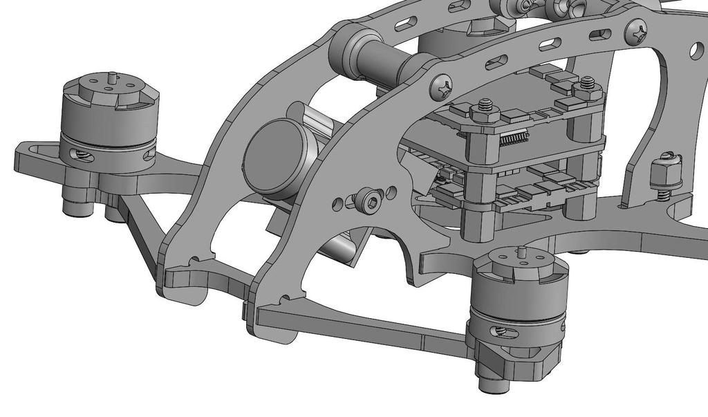
19 STEP 3 Parts Required: Quantity Part Description 1 Micro Stack Hardware Set (sold separately) 1 Micro All-in-one FC (sold separately) 1 Micro FPV Video Transmitter (sold separately) 1 Micro Receiver (sold separately) Assembly Process: Make all the necessary wiring connections between your ESC, flight controller, video transmitter, and receiver. Install the components as shown below. Please be aware the receiver is not pictured below but should be installed on top of the video transmitter using double sided stick tape.
20
21

22
23
24
25
26

27
28 STEP 4 Parts Required: Quantity Part Description 2 Roll bar plate (1.5mm Matte CF) 1 Front standoff - 19mm (Black 3D Printed Plastic) 1 Rear standoff - 19mm (Black 3D Printed Plastic) 1 Phillips head screw (#1 x 1/4" Long Steel) 4 Phillips head (#2 x 1/4 Long Steel) 2 Antenna tube (Black Plastic) Assembly Process: There are two ways to assemble the fuselage section of the Massive Droner onto the bottom frame plate. The first method is to pre-assemble the fuselage together and then attach it as one unit to the bottom plate. The alternative method is to join the Roll bar plates individually to the bottom plate, then install the standoffs last. Some electronics stacks will only allow for the alternative method. However, most will allow for the first method. For the purposes of this manual we only detail the first method in the pics below. Join the Roll bar plates together using the included standoffs and screws. Press the antenna tubes into the rear standoff as shown. There is a small hole just behind the tube in the carbon fiber plate. Run a small zip tie through this hole and around the tube to help hold it in place securely during crashes.

29

30

31
32 STEP 5 Parts Required: Quantity Part Description 2 Washer (M2.5 Steel) 2 Nylock nut (M2.5 Steel) 2 Socket head screw (M2.5 Silver Aluminum) Assembly Process: To install the fuselage onto the bottom plate position the front forks into the mating front slots at a slight angle. Then press the fuselage into place will positioning it's rear tabs into the rear slots of the bottom plate. Press the fuselage back until the holes in the bottom plate align with the captured nut cutout. To lock the fuselage in place each roll bar plate is held down with a screw, washer, and nut as show in the pics below. The process of feeding the screw through the bottom plate and installing the washer and nut can be a bit of a pain in the butt. It may take a few times to get it right. Don't give up and don't be a wuss. Don't whine and complain either. You have accomplished amazing things in your life. Don't let this tiny screw and nut beat you!

33

34

35

36
37
38 STEP 6 Parts Required: Quantity Part Description 1 Front arm brace (2.5mm Matte CF) 4 Socket head screw (M2 X 8mm Steel) Assembly Process: Our first batch of this frame includes a FREE rear brace in the kit. All subsequent production runs will NOT include this brace and it is available as an optional accessory. We do provide enough 8mm long screws in the kit to install both the rear and front brace. Installation of the rear brace is not covered in this manual but is an identical procedure as the front. While the rear brace is optional the front brace is not. You must install the front brace. If we find out you are flying your Droner without a front brace there will be hell to pay. To install it position as shown below. Then thread the screws through the brace and into the motors.

39
40
41

42
43 STEP 7 Parts Required: Quantity Part Description 1 Micro FPV Cam (Sold Separately) 2 Socket head screw (M2 X 4mm Steel) Assembly Process: The Droner will allow for installation of any micro camera on the market to date. At the time when this manual was created this includes the following: Runcam Micro Eagle, Runcam Micro Swift, Foxeer Micro, Foxeer Predator Micro, Runcam Split Mini, and HGL-RC Elf micro. Use the included screws to mount your camera of choice. Adjust the placement of the lens in reference to the forward edge of the roll bar plates by sliding it along the slots. Make sure to position the lens such that it sits just behind the plate so the camera is not damaged in a crash.

44

45
46

47 Final Steps: Assembly of your Droner is nearly complete. To finish him off run zip ties through the slots in the top rails to securely attach things like the FPV antenna, or provide stress relief for the receiver antennas. Don't forget to run the receiver antennas through the antenna tubes in the rear of the craft. Below is a picture of one of our Droner builds for reference. Congratulations on completing the most amazing micro FPV quad on planet earth! Feel free to hold your Massive Droner in your hand and show it to everyone you know. They will be happy to see it in person and proud of you for owning such a Massive Droner. There is no shame in your game.
FLOE DOCK FURNITURE WARNING ASSEMBLY INSTRUCTIONS
 FLOE DOCK FURNITURE ASSEMBLY INSTRUCTIONS KIT P/N 510-00400-02 KIT P/N 510-00405-02 KIT P/N 510-00406-02 KIT P/N 510-00410-02 WARNING IT IS THE INSTALLER S RESPONSIBILITY TO PROPERLY INSTALL this chair
This instruction manual is an in-depth look and explanation of how to assemble and install the Murphy Bed properly and efficiently.
 This instruction manual is an in-depth look and explanation of how to assemble and install the Murphy Bed properly and efficiently. Don t be put off by the size of the instruction manual as the large diagrams
Page 1 of 12 DZ /02/15
 Page 1 of 12 Dee Zee Running Board Installation Instructions Congratulations on your purchase of a quality Dee Zee product. Dee Zee is recognized as having the highest quality running boards and accessories
3DR ArduCopter Quad-C
 3DR ArduCopter Quad-C 3DR ArduCopter Quad-C Thank you for purchasing a 3DR ArduCopter Quad kit. The 3DR ArduCopter Quad is a stable and supported multi-rotor frame in the ongoing development of the ArduCopter
08+ KAWASAKI KLR PD NERF
 08+ KAWASAKI KLR PD NERF 0505-1299 Before you begin, place the bike on a hard level surface where you have room to work. Lay out the parts included in this kit and compare to the parts list on page 5 of
FlexRC Mini Owl - Extreme FPV Proximity Racing Drone - DIY Build Instructions
 FlexRC Mini Owl - Extreme FPV Proximity Racing Drone - DIY Build Instructions This guide will walk you through the detailed build steps using the FlexRC Mini Owl Extreme FPV Racing Drone DIY Kit. The kit
28in Super EVA Foam. F-22 Raptor Kit. Specifications. Wingspan: 27.5in (700mm) Length: 38.3in (975mm) Flying Weight: Approx. 1.
 Length: 38.3in (975mm) Flying Weight: Approx. 1.") 28in Super EVA Foam F-22 Raptor Kit Specifications Wingspan: 27.5in (700mm) Length: 38.3in (975mm) Flying Weight: Approx. 1.2lbs (530g) Dear Customer, Congratulations on your purchase of 28in F22 Raptor
28in Super EVA Foam F-22 Raptor Kit Specifications Wingspan: 27.5in (700mm) Length: 38.3in (975mm) Flying Weight: Approx. 1.2lbs (530g) Dear Customer, Congratulations on your purchase of 28in F22 Raptor
Arducopter 3DR-B Hardware
 Arducopter 3DR-B Thank you for purchasing an Arducopter 3DR kit. The Arducopter 3DR is a stable and supported quadrotor frame in the ongoing development of the Arducopter code on DIYDrones. It features
IMPORTANT! Recommended Tools. 7/16 Deep socket Phillips screwdriver
 IMPORTANT! Read all instructions carefully before commencing any work. Always wear proper safety equipment. Some installation steps will require two or more installers. Recommended Tools Ratchet 10-mm
Written By: Brook Drumm
 Simple 1401 Assembly For kits produced between 1/15/14-6/1/14. This guide is for kits with the Fan Shroud. Instructions for metal and wood extruder (and bed) included below. Written By: Brook Drumm TOOLS:
KAWASAKI KLRE PD NERF HTP4-8-5 & HIGHWAY PEGS HTP4-1-4B
 Thank you for purchasing Happy Trails products. Our products are proudly hand made in Boise Idaho, USA. If you have any questions or concerns about the installation of this product, please contact us directly
CAB END BEDTRAX (SIDE VIEW)
") Supplied Hardware: (8-14) 1/4-20 Allen head bolts, (12-18) UHMW mount blocks, (4) D-ring tie downs Tools Needed: Allen head wrench GET TO IT. INSTALLATION INSTRUCTIONS STEP 1. INSERT (2) MOUNT BLOCKS INTO
Supplied Hardware: (8-14) 1/4-20 Allen head bolts, (12-18) UHMW mount blocks, (4) D-ring tie downs Tools Needed: Allen head wrench GET TO IT. INSTALLATION INSTRUCTIONS STEP 1. INSERT (2) MOUNT BLOCKS INTO
OpenROV. Guide 3 - Electronics. We will now move to the assembly of the electronics that will control the ROV. Written By: OpenROV
 OpenROV Guide 3 - Electronics We will now move to the assembly of the electronics that will control the ROV. Written By: OpenROV 2017 openrov.dozuki.com Page 1 of 33 INTRODUCTION We will introduce soldering
F i t t i n g t h e N e w L a n d i n g G e a r t o Y o u r S k y J i b V 1
 F i t t i n g t h e N e w L a n d i n g G e a r t o Y o u r S k y J i b V 1 1 P a r t s L i s t : S t a n d a r d L a n d i n g G e a r U p g r a d e Product Code Parts + Spares Product Code Parts + Spares
Bashing The Hanger 9 Cessna 182 ARF Part 4
 Bashing The Hanger 9 Cessna 182 ARF Part 4 Eric Helms Pongo Air This is the final installment of a four-part article covering a variety of modifications incorporated into a Hanger 9 Cessna 182 ARF. Upgrades
(Build Instructions)
") (Build Instructions) Specifications * Wingspan: 58cm * Length: 50cm * Flying Weight: 59 grams * Channels: 3 (Rudder Elevator Throttle) * Suggested Receiver: 4Ch Micro * Motor: 8mm GearDrive * Prop: GWS
(Build Instructions) Specifications * Wingspan: 58cm * Length: 50cm * Flying Weight: 59 grams * Channels: 3 (Rudder Elevator Throttle) * Suggested Receiver: 4Ch Micro * Motor: 8mm GearDrive * Prop: GWS
DIY KITS FRAME KIT. Thank you for purchasing a 3DR Y6 DIY Kit!
 DIY KITS Y6 FRAME KIT Thank you for purchasing a 3DR Y6 DIY Kit! These instructions will guide you through assembling and wiring your new autonomous multicopter. CONTENTS Your 3DR Y6 Kit contains: 35 mm
This manual will aid in the assembly of the FireBall V90 and FireBall X90. The assembly of both machines will be identical, unless specified.
 This manual will aid in the assembly of the FireBall V90 and FireBall X90. The assembly of both machines will be identical, unless specified. Step #1 Lay all parts out to verify quantities. (2) 2 x 25-1/4
TRIUMPH TIGER 800 PD NERF
 TRIUMPH TIGER 800 PD NERF 0505-0 Step Before you begin, place the bike on a hard level surface where you have room to work. Lay out the parts included in this kit and compare to the parts list on page
INSTRUCTION BOOKLET #34. For Wallbed models: KING SIZE SIERRA WITH STORAGE HEADBOARD
 For Wallbed models: KING SIZE SIERRA WITH STORAGE HEADBOARD INSTRUCTION BOOKLET #34 WARNING! ALL MURPHY/WALLBED SYSTEMS CONTAIN STORED ENERGY. FAILURE TO USE AND FOLLOW THESE INSTRUCTIONS DURING THE INSTALLATION
SKID SET INSTALLATION INTERNAL COMPPONENTS AND PAYLOAD WING PACKING AND END PANEL/RIB TABS
 TABLE OF CONTENTS: BMP SCOUT USER GUIDE PROPELLER GUARD ARMS AND RING INSTALLATION GENERAL RADIO AND FAIL SAFE SET UP UNPACKING AND GETTING STARTED PROPELLER RING AND PROPELLER CLEARANCE PROPELLER INSTALLATION
High performance 90mm fiberglass jet
 High performance 90mm fiberglass jet Assembly manual For intermediate and advanced fliers only! Specs Wingspan: 1255mm Fuselage length: 1250mm Flying weight: 2600-3000g Wing area: 22.6 dm² Wing loading:
Atomic Mercury Frame Kit Assembly Manual
 Atomic Mercury Frame Kit Assembly Manual Thank you for purchasing the Atomic Aviation Mercury RACEframe! Please read through the entire manual first before beginning assembly of your kit. The order of
Patton Robotics ESRA II Expressive System for Robotic Animation
 Patton Robotics ESRA II Expressive System for Robotic Animation Assembly and Operation Instructions Version 1.0 Patton Robotics, LLC. 61 Hagan Drive New Hope, PA 18938 Copyright 2015 Patton Robotics, LLC.
Sirius instruction manual
 Sirius instruction manual Thank you for purchasing the eagle wing plane.the sirius is designed for First-Person-Vision (FPV) application spec ifically. Due to the high wingand push prop design, the on-board
Rugged Ridge 2 Receiver Hitch Kit (J21068)
") Rugged Ridge 2 Receiver Hitch Kit (J21068) Installation Time: 1-2 Hours Tools Required: ¾ Open End Wrench 18 mm Socket ¼ drive Pliers/Needle nose pliers/channel locks, etc. Torque wrench Phillips head
Rugged Ridge 2 Receiver Hitch Kit (J21068) Installation Time: 1-2 Hours Tools Required: ¾ Open End Wrench 18 mm Socket ¼ drive Pliers/Needle nose pliers/channel locks, etc. Torque wrench Phillips head
INSTALLATION INSTRUCTIONS
 INSTALLATION INSTRUCTIONS R5 STEP BOARD APPLICATION: 2009-2017 Dodge Ram 1500 Quad / Crew Cab 2010-2017 Dodge Ram 2500/3500 Crew Cab PART NUMBER: 28-51040, 28-51045, 28-51050, 28-51055 ITEM QUANTITY DESCRIPTION
Skywalker X8 Installation Manual
 Skywalker X8 Installation Manual Thank you for Purchasing the Skywalker X8 FPV Plane from FPV Model. The Skywalker X8 is specially designed for First Person View (FPV) purpose. Technical Parameters Wingspan:
INVENT3D Printer Kit Disassembly Instructions
 INVENT3D Printer Kit Disassembly Instructions Version 6 AST2 10/26/16 1 I. General Disassembly Instructions Use the case layer drawings to ensure that components are stored in the appropriate location
 For Wallbed models: KING SIZE INSTRUCTION BOOKLET #C1 Watch step by step installation instructions at: https://www.wallbedsbywilding.com/wallbed-installation-studio-series/ WARNING! ALL MURPHY/WALLBED
RC4WD Diablo V2 Instruction Manual
 Version 1.1 RC4WD Diablo V2 Instruction Manual Thank you for your purchase. Welcome to the RC4WD family. This kit is a combination of many specially engineered and manufactured parts. Enjoy your build.
BEAST THE. Tube and Pipe Notcher Operating Instructions. Notches In Bends Straight Notches. Angled Notches. Offset Notches
 Copyright (c) 2007 J D SQUARED INC. www.jd2.com THE BEAST Tube and Pipe Notcher Operating Instructions Notches In Bends Straight Notches Angled Notches PATENT PENDING Offset Notches Assembly After unpacking
Side Mount INSTRUCTION BOOKLET #C122 BED STYLE: PARK CITY
 Side Mount BED STYLE: PARK CITY INSTRUCTION BOOKLET #C1 WARNING! ALL MURPHY/WALLBED SYSTEMS CONTAIN STORED ENERGY. FAILURE TO USE AND FOLLOW THESE INSTRUCTIONS DURING THE INSTALLATION PROCESS COULD RESULT
Medium HoneyBadger Chase Rack Installation Instructions
 PREPARATION Medium HoneyBadger Chase Rack Installation Instructions 1. Disconnect the negative terminal on the battery. Park the vehicle on level ground and set the emergency brake. 2. We recommend reading
43in EPP Acrocub Instruction Manual
 43in EPP Acrocub Instruction Manual Specifications Wingspan: 43.3in (1100mm) Length: 41.3in (1050mm) Flying Weight: Approx. 1.5lb (670g) Dear Customer, Congratulations on your purchase of 43in EPP Acrocub
SS1062, SS10621 & SS10621E Free Standing PWC & Fishing Boat Hoist SS1062 SS10621 SS10621E
 SS1062, SS10621 & SS10621E Free Standing PWC & Fishing Boat Hoist SS1062 SS10621 SS10621E Midwest Industries, Inc. Page 1 Ida Grove, IA 51445 800.859.3028 www.shorestation.com 0003231 REV A 1/25/05 Bundles
4099T Parts List. Front Bow Assy. (1) Rear Bow Assy. (1) Long Mounting Rail (2) Short Mounting Rail (2)
 Rear Bow Assy. (1) Long Mounting Rail (2) Short Mounting Rail (2)") 4099T Parts List Ver.2 Front Bow Assy. (1) Rear Bow Assy. (1) Small Mnt Foot (2) Large Mount Foot (2) Ladder Hook (2) Ladder Stop (2) Handle Extension (1) Long Mounting Rail (2) Short Mounting Rail (2)
4099T Parts List Ver.2 Front Bow Assy. (1) Rear Bow Assy. (1) Small Mnt Foot (2) Large Mount Foot (2) Ladder Hook (2) Ladder Stop (2) Handle Extension (1) Long Mounting Rail (2) Short Mounting Rail (2)
INSTRUCTION BOOKLET #C20
 INSTRUCTION BOOKLET #C0 WARNING! ALL MURPHY/WALLBED SYSTEMS CONTAIN STORED ENERGY. FAILURE TO USE AND FOLLOW THESE INSTRUCTIONS DURING THE INSTALLATION PROCESS COULD RESULT IN SEVERE PERSONAL INJURY TO
PRODUCT: JK Hardline Front Fender READ INSTRUCTIONS IN FULL BEFORE INSTALLATION. QUESTIONS? CALL M-F 7:00 AM 5:00 PM PST
 PRODUCT: JK Hardline Front Fender READ INSTRUCTIONS IN FULL BEFORE INSTALLATION. QUESTIONS? CALL 916-631-8071 M-F 7:00 AM 5:00 PM PST REV: D 05-30-2017 II-3205 The MetalCloak experience includes the ease
https://www.wallbedsbywilding.com/wallbed-installation-studio-series/
 For Wallbed models: KING SIZE INSTRUCTION BOOKLET #C1 Watch step by step installation instructions at: https://www.wallbedsbywilding.com/wallbed-installation-studio-series/ WARNING! ALL MURPHY/WALLBED
Venturi EVO 2 FPV. Thank you for purchasing the Venturi EVO FPV wing
 Thank you for purchasing the Venturi EVO FPV wing The Venturi FPV is designed for First Person Viewing (FPV) and for UAV/Drone experimentation. There is a power system for this model, see the website for
GlideRite Retractable Cover System For HotSpring & Tiger River Spas (except Classic & pre-2000 Landmark Spas)
") List of Contents Quantity Description 12 #10 x 1 ½ Flat Head Phillips Screw (see pg. 2) 2 #10 x ½ Pan Head Phillips Screw (see pg. 2) 8 ¼ x 2 ½ Lag Bolt (see pg. 2) 7 ¼ 20 x 5 / 8 Hex Head Bolt (see pg.
List of Contents Quantity Description 12 #10 x 1 ½ Flat Head Phillips Screw (see pg. 2) 2 #10 x ½ Pan Head Phillips Screw (see pg. 2) 8 ¼ x 2 ½ Lag Bolt (see pg. 2) 7 ¼ 20 x 5 / 8 Hex Head Bolt (see pg.
INSTRUCTION BOOKLET #C21. For Wallbed models: KING SIZE
 For Wallbed models: KING SIZE INSTRUCTION BOOKLET #C1 WARNING! ALL MURPHY/WALLBED SYSTEMS CONTAIN STORED ENERGY. FAILURE TO USE AND FOLLOW THESE INSTRUCTIONS DURING THE INSTALLATION PROCESS COULD RESULT
TIRE RACK INSTALLATION INSTRUCTIONS Dodge Sprinter
 Aluminess Products Inc 9402 Wheatlands Ct. #A Santee, CA 92071 619-449-9930 TIRE RACK INSTALLATION INSTRUCTIONS 07-11 Dodge Sprinter Please read before beginning Stainless steel hardware may bind together
F l a t S c r e e n A R M S I n s t a l l a t i o n
 ITEM NUMBERS (1) #TOACAORG16 (2) #TOACAORG20 (3) #TOACATRP24 (4) #TOACATRP30 (5) #TOACATRPDS (6) #TOACATRPSS TOOLS REQUIRED (1) 3/8 Wrench (not provided) (2) Phillips head screwdriver (not provided) (1)
M2 Antenna Systems, Inc. Model No: 450CP34
 M2 Antenna Systems, Inc. Model No: 450CP34 SPECIFICATIONS: Model... 450CP34 Frequency Range... 435 To 455 mhz *Gain... 16.0 dbi Front to back... 22 db Typical Beamwidth... 28 Circular Feed type... T Match
RBP-1215B-RX DODGE RAM QUAD CAB RX3
 RBP-1215B-RX3 2002-2017 DODGE RAM 15-3500 QUAD CAB RX3 Passenger side RX-3 Side Step Drill Template Passenger side rear Modular Bracket (6) L Support Brackets Driver side rear Modular Bracket Driver side
SINCE 1922 P UBLICATION N O
 SINCE 1922 GARED SPORTS MICRO-Z SET-UP INSTRUCTIONS VERY IMPORTANT! READ INSTRUCTIONS CAREFULLY AND FOLLOW STEP BY STEP SET-UP PROCEDURE P UBLICATION N O. 5 5 1 7 5 2 9 1 6 Recommended tools and accessories.
INSTALLATION MANUAL FRONT. See pages 2 and 3 of this manual for configuration options. Level of Difficulty. Product Photo (center section only)
") INSTALLATION MANUAL FRONT Level of Difficulty Moderate Product Photo (center section only) All hardware listed below will be provided with the bumpers center section. Additional hardware will be supplied
INSTALLATION MANUAL FRONT Level of Difficulty Moderate Product Photo (center section only) All hardware listed below will be provided with the bumpers center section. Additional hardware will be supplied
EZ BALANCER II. Please note: The hardware and accessories listed may not be the same as shown. We are always improving the product.
 Parts List EZ BALANCER II 2ea. Aluminum Angle Base Frame Members. 2ea. 1/2"x1" Aluminum Angle Cross Frame Members. 2ea. Aluminum Uprights. 2ea. Aluminum Cradles. 4ea. Rubber Cradle Guards. 4ea. Rubber
BY ALIEN TECHNOLOGIES CORP
 BY ALIEN TECHNOLOGIES CORP Assembly Instructions TopLift Pros YOU MAY ALSO REVIEW OUR ASSEMBLY VIDEO, PLAY AND PAUSE AT YOUR CONVENIENCE. JUST VISIT US AT WWW.TOPLIFTPROS.COM AND GO TO Customer Support
STEP 1 STEP 2 LEVELER KIT OPTION MOBILE CASTER KIT OPTION
 B SERIES INDUSTRIAL BENCHES TOOLS REQUIRED FOR ASSEMBLY Socket set, Open end wrench set, Cordless drill with 3/8" socket bit (Magnetic recommended). BEFORE ASSEMBLY Read through the assembly instructions
For additional assistance call
 The following pages will help guide you through the process of assembling your new 48 custom prize wheel. Choose an assembly area with plenty of room to lay your pieces on the floor and also a bench or
Pickup Box Utility Rack Package Installation (Instruction ID: )
") 017 Chevrolet Colorado Pickup - WD (VIN S) Canyon, Colorado Accessory Installation Manual N America Document ID: 3966961 Pickup Box Utility Rack Package Installation (Instruction ID:3144879) Installation
017 Chevrolet Colorado Pickup - WD (VIN S) Canyon, Colorado Accessory Installation Manual N America Document ID: 3966961 Pickup Box Utility Rack Package Installation (Instruction ID:3144879) Installation
 INSTRUCTION BOOKLET #C10 Watch step by step installation instructions at: https://www.wallbedsbywilding.com/wallbed-installation-studio-series/ WARNING! ALL MURPHY/WALLBED SYSTEMS CONTAIN STORED ENERGY.
INSTALLATION INSTRUCTIONS FOR FRONT CASTING DECK RAIL Ranger
 INSTALLATION INSTRUCTIONS FOR FRONT CASTING DECK RAIL Ranger TOOLS REQUIRED FOR INSTALLATION: Drill motor, (1) 5/16 inch drill bit, (1) 13/64 drill bit, (1) 3/16 inch hex wrench (1) 3/32 inch hex wrench.
MODULAR BUMPER INSTALLATION MANUAL
 MODULAR BUMPER INSTALLATION MANUAL Parts List* 1 Center section 1 Side extension, passenger / right 1 Side extension, driver / left 1 Side cap, passenger / right 1 Side cap, driver / left 1 Brush guard,
RPS. XR Front Drive Updates CORPORATION
 FACTORY CAT 1. To start a replacement of the XR Front Wheel Drive, make sure the machine is on level ground with the rear wheels chocked and always disconnect the batteries. 2. Locate the Positive and
CNC Router Parts PRO Machine Kit Cable Track Installation Instructions
 1 1 X CABLE TRACK TRAYS & BRACKETS The cable track on the side of the system is supported by a metal tray (or multiple trays for longer systems such as a PRO4896). These trays hang from brackets on the
Gared Pro-S Portable Backstop
 Models: 9616 & 9618 Installation, Operation and Maintenance Instructions Please read all instructions before attempting installation or operation of these units SAVE THESE INSTRUCTIONS FOR FUTURE USE PUBLICATION
* Drill and 3/32" drill bit: for drilling holes in the factory plastic upper for the screws to secure the brackets (factory upper installation only)
") * Two slider windows (four sliders windows for the 4-door kit) * Four brackets to secure the windows to the upper door frames (8 brackets for the 4-door kit) * Weatherstrip to seal the windows to the half
* Two slider windows (four sliders windows for the 4-door kit) * Four brackets to secure the windows to the upper door frames (8 brackets for the 4-door kit) * Weatherstrip to seal the windows to the half
Dream Fabric Frame Assembly Instructions
 Dream Fabric Frame Assembly Instructions Copyright May 01, 2015 Jim M. Bagley, GraceWood, Inc (Reproduction Prohibited) Version 1 Table Of Contents Parts List 3 Step 1: Table Set Up 6 Step 2: Install the
Starving Student II. Starving Student II. SS2 guide. Written By: 6L guides.diyaudio.com/ Page 1 of 24
 SS2 guide Written By: 6L6 2019 guides.diyaudio.com/ Page 1 of 24 INTRODUCTION This is a build guide for the hybrid headphone/pre-amplifier. You can buy a kit at the SSII product listing on the diyaudio
Removing outter components
 Y Axis Motor Replacement Replacing the Y axis motor is a process that requires the individual to be somewhat mechanically inclined and can follow detailed instructions. If any of the following steps are
Super Sky Surfer 2000 Assembly Instructions
 Super Sky Surfer 2000 Assembly Instructions Note: Plug and Play version of the Sky Surfer comes with fuselage pre-glued and motor/servos installed. If you wish to route antennas or wires through the tail,
 INSTRUCTION BOOKLET #C0 Watch step by step installation instructions at: https://www.wallbedsbywilding.com/wallbed-installation-studio-series/ WARNING! ALL MURPHY/WALLBED SYSTEMS CONTAIN STORED ENERGY.
ASSEMBLY & INSTALLATION INSTRUCTIONS
 ASSEMBLY & INSTALLATION INSTRUCTIONS VEHICLE MOUNT KIT 118 AND VEHICLE CENTER MEMBER 6050 TO FIT 2008 & LATER FORD F250-F550 4X4 Sno-Way, Down Pressure and EIS are registered trademarks of Sno-Way International,
RC4WD (R2D) R2 Disconnect Transmission Sideway Servo Mount Installation
 R2 Disconnect Transmission Sideway Servo Mount Installation") RC4WD (R2D) R2 Disconnect Transmission Sideway Servo Mount Installation In this manual you will find out how to install the R2D Sideway servo mount. The disconnect tranny is used to help in competition
RC4WD (R2D) R2 Disconnect Transmission Sideway Servo Mount Installation In this manual you will find out how to install the R2D Sideway servo mount. The disconnect tranny is used to help in competition
INSTALLATION GUIDE Rear Bumper. Jeep JL Wrangler
 INSTALLATION GUIDE Rear Bumper Jeep JL Wrangler Dual Swing System 1A From the stock bumper you removed from vehicle, you ll need to take the parking sensor wiring from it and feed it into the new bumper.
GlideRite Retractable Cover System For Hot Spot Spas (SE & SLX only)
") List of Contents Quantity Description 12 #10 x 1 ½ Flat Head Phillips Screw (see pg. 2) 2 #10 x ½ Pan Head Phillips Screw (see pg. 2) 8 ¼ x 2 ½ Lag Bolt (see pg. 2) 7 ¼ 20 x 5 / 8 Hex Head Bolt (see pg.
List of Contents Quantity Description 12 #10 x 1 ½ Flat Head Phillips Screw (see pg. 2) 2 #10 x ½ Pan Head Phillips Screw (see pg. 2) 8 ¼ x 2 ½ Lag Bolt (see pg. 2) 7 ¼ 20 x 5 / 8 Hex Head Bolt (see pg.
Kossel Rev B Build Guide V1.0
 Kossel Rev B Build Guide V1.0 1 Table of Contents: Step 1: BASE ASSEMBLY Gathering parts: Building the Corners and Base: Step 2: UPPER ASSEMBLY Building Upper: Step 3: VERTICAL RAIL INSTALLATION Building
Dream Fabric Frame Assembly Instructions
 Dream Fabric Frame Assembly Instructions Copyright January 1, 2016 Jim M. Bagley, GraceWood, Inc (Reproduction Prohibited) Version 2.4 Table Of Contents Parts List 3 Step 1: Table Set Up 6 Step 2: Install
Sbach 1,2m 3D/aerobatic EPP model Building instructions
 Sbach 1,2m 3D/aerobatic EPP model Building instructions Please refer to the Diagram sheet Diagrams A, B Press 2 carbon strips (1x3x1000 mm) into the grooves in the sides of the fuselage central part (the
MPA-9000 Universal Ceiling Projector Mount Kit
 I N S T R U C T I O N M A N U A L Universal Ceiling Projector Mount Kit The Universal Ceiling Projector Mount provides a unique, simplified method of ceiling mounting your inverted projector. This low
INSTALLATION INSTRUCTIONS
 INSTALLATION INSTRUCTIONS For Wallbed models: Do-It-Yourself BOOKLET #C90 WARNING! ALL MURPY/WALLBED SYSTEMS CONTAIN STORED ENERGY. FAILURE TO USE AND FOLLOW THESE INSTRUCTIONS DURING THE INSTALLATION
INSTALLATION INSTRUCTIONS
 INSTALLATION INSTRUCTIONS SNYPER TUBULAR FENDERS APPLICATION: 2007-2017 Jeep Wrangler JK PART NUMBER: 62-1005, 62-1015 ITEM QUANTITY DESCRIPTION TOOLS NEEDED 1,2 2 FRONT FENDERS, DRIVER (1) AND PASSENGER
M2 Antenna Systems, Inc. Model No: 450CP26
 M2 Antenna Systems, Inc. Model No: 450CP26 SPECIFICATIONS: Model... 450CP26 Frequency Range... 445 To 455 mhz *Gain... 16.5 dbi Front to back... 21 db Typical Beamwidth... 30 Circular Feed type... T Match
Installation Instructions for Cirrus Suspension Downlight with Power - End Feed. Section One: 4" Flush Canopy Version
 Doc # 0-CSP-E_0 W. Fullerton Chicago, IL 606 Ph:.0. Fax:..6 www.pureedgelighting.com info@pureedgelighting.com 06 PureEdge Lighting. All Rights Reserved. Installation Instructions for Cirrus Suspension
INSTALLATION INSTRUCTIONS
 AUTOMOTIVE PRODUCTS, INSTALLATION INSTRUCTIONS PLATINUM 4 OVAL STEP BAR (90 BENT END) APPLICATION: 2010-2015 Dodge Ram 2500/3500 Mega Cab PART NUMBER: 21-3570, 21-3575, 23-3570, 23-3575, 25-3570, 25-3575,
The Queen Quilter Professional Quilters Kit Frame
 The Queen Quilter Professional Quilters Kit Frame Assembly Instructions Table of Contents: Before you begin......................... Pg. 2 Wood parts............................. Pg. 3 Hardware..............................
O-Sullivan King 4 Poster Bed O-Sullivan Queen 4 Poster Bed Parts and Hardware List
 Parts and Hardware List A. Left Headboard Post 1 pc B. Right Headboard Post 1 pc C. Left Footboard Post 1 pc D. Right Footboard Post 1 pc E. Headboard Panel 1 pc F. Footboard Rail 1 pc. Spindles 4 pcs
"The Stick" Assembly Instructions
 Back to Main Page "The Stick" Assembly Instructions In Japanese (pdf): right click and save target as. Introduction: Hello and thank you for buying a Stick chassis from TCS. We appreciate your business
Directive Systems & Engineering 2702 Rodgers Terrace Haymarket, VA
 Directive Systems & Engineering 2702 Rodgers Terrace Haymarket, VA 20169-1628 www.directivesystems.com 703-754-3876 25 Element 7.4 wl. K1FO Designed Yagi, Model DSEFO432-25 ELECTRICAL SPECIFICATIONS Frequency
RAMPAGE P R O D U C T S. INSTALLATION INSTRUCTIONS BRONCO ZIPPER FASTRACK TOP PART #984xx BRONCO TOOLS REQUIRED
 RAMPAGE P R O D U C T S 84 (+/- 1/4 ) INSTALLATION INSTRUCTIONS BRONCO ZIPPER FASTRACK TOP PART #984xx BRONCO 1966-1977 TOOLS REQUIRED 3/8 WRENCH 7/16 WRENCH ½ WRENCH #2 PHILLIPS SCREWDRIVER 1/8 DRILL
Ribcage Installation. Part 2 - Assembly. Back-Bone V1.06
 Ribcage Installation Part 2 - Assembly Back-Bone V1.06 Contents Section 1 Before You Get Started... 2 Included With Your Kit:... 2 Figure: A... 3 CAUTION!... 4 Note:... 4 Tools Required... 5 Section 2:
CALIBURN ASSEMBLY INSTRUCTIONS
 CALIBURN ASSEMBLY INSTRUCTIONS The Caliburn is a Mag-Fed Pump-Action Homemade Nerf Blaster design released as a Public Domain license file set by Captain Slug (http://www.captainslug.com). You are welcome
Installation Instructions for FC2 & FC15 Forward Controls for the Super Magna
 Installation Instructions for FC2 & FC15 Forward Controls for the Super Magna It is highly recommended that you use a thread lock compound such as Loctite brand on all threads to keep them from vibrating
Bunk Pod Front Entry Assembly Instructions
 Bunk Pod Front Entry Assembly Instructions www.podtime.co.uk enquiries@podtime.co.uk Working House Ltd How to assemble your pod This step by step guide will show how to assemble your pod(s) on site. It
Allow 60 from door face
 Setbacks Allow 60 from door face TOOLS NEEDED Tape Measure Marker or Pencil Masonry Drill Bit 3/8 Hammer Drill Hammer Socket Wrenches and Wrench: 9/16, 1/2, 7/16, 1/4 drive socket wrench and 1/2 socket
WILDING WALLBEDS INSTALLATION INSTRUCTION Side Mount
 WILDING WALLBEDS INSTALLATION INSTRUCTION Side Mount For Wallbed models: Do-It-Yourself Insturction booklet C92 WARNING! ALL MURPHY/WALLBED SYSTEMS CONTAIN STORED ENERGY. FAILURE TO USE AND FOLLOW THESE
The ability to make basic voltage and resistance measurements using a digital multimeter
 Congratulations on your purchase of a new OneShot chassis! The PC01 OneShot combines a rugged enclosure, power supply, and discrete instrument DI in a compact 1/4U package. A few minutes of assembly are
PAC-12 Kit Contents. Tools Needed Soldering iron Phillips screwdriver Wire stripper Wrenches, 7/16 and 1/2 Terminal crimp tool Pliers Solder
 PAC-2 Kit Contents Part Quantity Screws: 8/32 x 3/8 Screws: 8-32 x 5/6 Screw: 8-32 x /4 #8 internal tooth washers #8 solder lug ring terminals Bolt: Aluminum, /4-20 x.5 /4 internal tooth washer Nut: Aluminum
Parts list Instruction guide Warnings Please read carefully before assembling and using product.
 Parts list Instruction guide Warnings Please read carefully before assembling and using product. Jet Rail XL Part Number 27377 Tools required for assembly Hammer 9/16 Wrench 3/4 Wrench Ratchet 9/16 Socket
ULS Cherokee. Ultra Low Speed aircraft for indoor RC flying. Zippkits. Specifications: Required to complete:
 Zippkits ULS Cherokee Ultra Low Speed aircraft for indoor RC flying. Specifications: Span- 28 inches Wing Area- 151 Sq/In Wing Loading- 3.0 ounces/ft Weight- 3.5 ounces RTF Build time- 1-2 Hours Radio-
Pro-Lock Retrofit Instruction Manual
 Pro-Lock Retrofit Instruction Manual The manual provided here lists detailed steps on the most effective way to replace your Hurd and OEM Locks with a Pro- Lock unit. The steps outlined in this procedure
Box Track INSTALLATION INSTRUCTIONS
 Box Track INSTALLATION INSTRUCTIONS BOX TRACK Recommended Tools Level Tape Measure Pencil Drill with 1/8, and 1/4, Drill Bits, Phillips Bit and Slotted Bit Socket Wrench with 9/16 Socket 9/16 and 5/8 Wrench
======================================================================================== ( DR / DR) JK WRANGLER MOD RACK
 JK WRANGLER MOD RACK") (10984 4DR / 10982 2DR) JK WRANGLER MOD RACK INSTALLATION SHEET Important Notes: Some brands of windshield light brackets and snorkels may not be compatible with the 10984 MOD Rack System. Body lifts are
(10984 4DR / 10982 2DR) JK WRANGLER MOD RACK INSTALLATION SHEET Important Notes: Some brands of windshield light brackets and snorkels may not be compatible with the 10984 MOD Rack System. Body lifts are
Parts and tools needed for installation- Cleaning and Painting -
 Thank you for the purchase of our JK Rear Trail Doors. We have made these from 6061-T6 aluminum and reinforced them with stiffeners at the top that double as a comfortable armrest and support for Rugged
V4 Premium Kit. Prusa i3 Build Guide
 V4 Premium Kit Prusa i3 Build Guide Hi! Congratulations on your purchase of the DIYElectronics.co.za Prusa I3 kit, the best South African 3D Printer Kit! Hopefully this should serve as complete guide to
3/8-16 x 3/4 cap screw. 3/8-16 hex nut for above screws. 1/4-20 x 3/4 socket cap screw. 3/16 short arm hex key (not to scale)
") Super Slab Roller 24, 30 and 36 models Worktable Assembly Directions P.O. Box 89 Cheney, WA 99004 USA 509.235.9200/800.23.7896 Fax: 509.235.9203 www.northstarequipment.com Revised September, 2006. All
Super Slab Roller 24, 30 and 36 models Worktable Assembly Directions P.O. Box 89 Cheney, WA 99004 USA 509.235.9200/800.23.7896 Fax: 509.235.9203 www.northstarequipment.com Revised September, 2006. All