Atomic Mercury Frame Kit Assembly Manual
|
|
|
- Brook Jones
- 6 years ago
- Views:
Transcription
1 Atomic Mercury Frame Kit Assembly Manual Thank you for purchasing the Atomic Aviation Mercury RACEframe! Please read through the entire manual first before beginning assembly of your kit. The order of assembly steps has been carefully considered - we recommend following the instructions in the order they are presented. The stressed skin design of this aircraft requires tight tolerances at each tab and slot fitting. The stiffness of your aircraft frame will depend on achieving a snug fit of these tabs into their slots. It is worth taking time to test fit the parts before removing material. In most cases, mating parts can be worked into place without having to resort to a file or hobby knife, and this will ultimately result in a stiffer airframe. Note that in some cases your kit might ship with updated components that are slightly different from those used to produce the photographs used in this manual. This is normal as we will only update the assembly manual for major product revisions requiring a new build order. Before beginning construction, please make sure your kit includes the following components: FRAME PARTS base plate 1 side plate 2 top plate 1 front LED mounting plate 1 rear LED mounting plate 1 motor mount plates 4 tabbed motor mount attachment 4 non-tabbed motor mount attachment 4 boom arm 2 FRAME HARDWARE aluminum boom clamp (2 halves) 4 XT60 connector 1 XT60 clamp 1 M3 x 30 cap screw 4 QTY M3 x 4 button head screw 16 M3 x 16 nylon screw 4 M2.5 x 14 button head screw 8 M2.5 x 6 cap screw 8 M2.5 x 6 button head screw 2 M3 x 3 nylon spacer 4 M3 x 5 nylon spacer 4 M3 hex nut 4 M3 nylon nut 4 M2.5 anodized aluminum washers 8 o-ring 4 1


2 1. Use a small file or hobby knife to trim sprue flashing from the frame plates and booms. NOTE: Be careful to distinguish between flashing, which must be removed, and functional tabs that are required for assembly of the frame. 2. Position the base plate as shown on your work surface. This plate is not symmetrical - take careful note of the hole pattern at the rear which indicates correct orientation. The front of the frame is at the top of the picture. If building with the optional carbon fiber base plate, the top has a matte finish and the bottom has a semi-gloss finish. 2


3 3. Insert a M2.5 x 14 button head screw from the bottom of the hole shown below. 4. Mount the XT60 battery connector to the underside of the frame using the aluminum mounting bracket and 2 M2 x 6 button head screws as shown. You ll notice that the bracket has a small raised section on one side of it. It corresponds to an indentation on the connector (where it says XT60). Make sure these line up as you install the bracket. 3

4 5. Remove the aluminum boom clamps from the bag of hardware and separate them into two piles according to whether they have threaded holes or through holes. 6. Mount the boom clamps to the base plate using the remaining M2.5 x 14 screws. The screws insert through the base plate from underneath, pass through the lower clamp half (with through holes), and finally thread into the upper clamp half (with threaded holes). Tighten the screws just enough to keep the clamp halves in place; it is not necessary to fully tighten the screws at this time. 7. Mount the side plates on the base plate. Note that the side plates have a top and a bottom and a front and rear. Review the photo below to ensure they are oriented correctly. The hook is at the top, and points forward, away from the battery hookup. Start at the middle tab/slot and carefully bend a side plate into position to fit the next tab 4


5 into a slot, working first toward the rear, then the front. Repeat until the entire side plate is formed into position. 8. Install the booms by sliding them through the side plates and boom clamps. The holes in the booms should be located between the boom clamps and should point inward, towards the center of the frame as shown. NOTE: The LEDs, camera, and other electronics are not included with this kit. Installation of these components is easiest if done at this time, before completing final assembly of the frame. Some helpful hints for installing your electronics are provided below. If you are just assembling the frame by itself to test fit the parts, skip to step 17 and disregard any wiring suggestions. 9. Glue the LEDs into the front and back mounting bars using silicone or other flexible adhesive. The front LEDs should be installed in the configuration shown - with the camera orientation notch pointing to the right. Let the silicone adhesive dry with the mounting bars under the weight of a large book or other heavy object. When the silicone is dry, clean any expunged silicone from the LED mounting bars with a hobby knife. 5


6 NOTE: Thinking ahead now about routing the LED wiring will make this much easier when we get to it in a future step. Whether you are installing fixed color LEDs or addressable LEDs, read ahead to the relevant steps to understand how we recommend routing the wiring. 10. Test fit the camera into the front LED mounting bar and temporarily install it onto the frame. Observe the angle at which the lead wires must leave the camera in order for them to run properly under the front boom. Be gentle while working with the camera wires as they are thin and will break if over-flexed. 11. Carefully remove the camera and manipulate the lead wires into the required exit angles. Apply 5 minute epoxy or hot glue to the back of the camera board to provide protection as well as strain relief to the wires. 6


7 12. The 4 nylon M3 x 16 screws and assorted nylon spacers are included for mounting your PDB and flight controller stack. The screws should be inserted from underneath. With the PDB installed, complete wiring for your battery connector, ESCs, and accessories. With all electronics are wired, install your flight controller and complete the required connections. 7


 to each lead.")
8 13. LED installation is slightly different depending on whether fixed color LEDs or addressable LEDs are being used. See 13a for tips on installing fixed color LEDs, or 13b for addressable LEDs. a. Fixed color LEDs are powered directly from the 12V regulator on your PDB. Remove the adhesive backing from the LED strips and scrape away the glue from the solder points. Note that only the inner solder points on the front bar and center solder points on the rear bar must be cleaned. Solder small lengths of 24/26AWG wire to connect the positive and negative terminals of the two LED strips on the front LED mounting bar. Carefully trim a small section of insulation from the middle of each wire and solder a 100mm power line (24/26AWG) to each lead. Use the camera as a guide to make sure that these power leads will not interfere with the camera when installed. Solder a 24/26AWG power lead to the central power leads of the rear LED strip. Remove the front and rear LED mounting bars and spray the backs with black spray Plasti-Dip (preferred) or black spray paint. Set the LED mounting bars aside to dry. 8


9 b. Addressable LEDs (WS2812) are installed differently, requiring 5V power from your PDB and a signal wire from your flight controller. They have a directionality with an input side and an output side indicated by printed arrows on the strip, and they must be daisy-chained together to work properly. We recommend wiring them as shown with the right/rear corner as the beginning of the chain, and the left/front corner the end. Installation of a connector at the left/front corner as shown will simplify future removal of the front LED bar in the event the camera requires service. 9


10 14. Install the camera into the front LED mounting bar. Install both front and back LED mounting bars onto the frame, routing the camera and LED wiring underneath the booms. Solder the LED power leads to the appropriate terminals on your PDB. 15. Route the motor leads through the booms. This process is made easier by crossing the wires left-to-right and right-to-left as they enter the boom. In this way, the ESCs on the left of the aircraft will drive the motors on the right and vice versa. 10


11 16. Fix the motors to the motor mount plates using 4 M3 x 4mm screws for each motor. The lead wires should point toward the side with the two longer, rounded tabs as shown. Note that the motor mount plates each have a large and small bump on opposite sides of one another. The large bump is intended to protect the motor in the event of a collision and so must face forward on the front motors and backwards on the rear motors. 17. Each motor mount sub-assembly is built by attaching one tabbed plate and one non-tabbed plate to each motor mount. The tabbed plate mounts to the side with the motor wire leads as shown. A small file can be used to open the slots in these plates if they are difficult to slide on. NOTE: These plates should fit snugly, and opening the slots to the point of being loose will adversely affect the performance of the aircraft. 11


12 18. Slide an o-ring onto each motor arm. Build the motor mounts onto the booms. Secure each assembly with an M3 x 30 screw and M3 nut. As mentioned earlier, the bumpers on the motor mount plates face outward, to protect the motors in a collision. 19. Mount the coax extension for your video transmitter into the hole at the back of the top plate as shown. 20. Before installing the top plate, finish installing and test all electronics. 12
 Begin at the hooked tabs near the middle.")
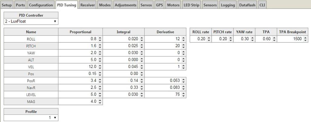
13 21. Mount the aircraft top plate to the frame. The front of the top plate has the Atomic Aviation logo laser etched into it. (An optional colored top plate is shown to make the position of the logo more clear.) Begin at the hooked tabs near the middle. Hook the top plate then move toward the front aligning the tabs as you go. Use 4 M2.5 x 6 cap screws and aluminum screw skirts to secure the front section. Do the same with the rear of the top plate and secure with the remaining cap screws and skirts. Finally, use the o-rings to secure the ends of the front and rear LED bars. 22. There are many flight controllers and flight control software options in the world of FPV racing today. Tuning your flight controller depends heavily on motor and prop size, battery voltage, not to mention personal preference. The following screenshot shows a sample tune for Mercury with a Naze32 flight controller running Cleanflight with kV motors, 6x4.5 props, and a 4S battery. 13
14 14
FlexRC Mini Owl - Extreme FPV Proximity Racing Drone - DIY Build Instructions
 FlexRC Mini Owl - Extreme FPV Proximity Racing Drone - DIY Build Instructions This guide will walk you through the detailed build steps using the FlexRC Mini Owl Extreme FPV Racing Drone DIY Kit. The kit
Super Sky Surfer 2000 Assembly Instructions
 Super Sky Surfer 2000 Assembly Instructions Note: Plug and Play version of the Sky Surfer comes with fuselage pre-glued and motor/servos installed. If you wish to route antennas or wires through the tail,
(2) 25mm x 20mm x 5mm Adhesive Backed Foam Pads. 100mm x 50mm x 1.0mm Adhesive Backed Foam. (2) Spacer Plates. Passenger/Right Side Frame Mounting
 25mm x 20mm x 5mm Adhesive Backed Foam Pads. 100mm x 50mm x 1.0mm Adhesive Backed Foam. (2) Spacer Plates. Passenger/Right Side Frame Mounting") PARTS LIST: 1 Grille Guard 10 12mm Lock Washers 1 Driver/Left Frame Mounting 16 12mm x 32mm OD x 3mm Flat Washers 1 Passenger/Right Frame Mounting 8 12mm Hex Nuts 1 Driver/Left Side Top Support 2 10-1.50mm
PARTS LIST: 1 Grille Guard 10 12mm Lock Washers 1 Driver/Left Frame Mounting 16 12mm x 32mm OD x 3mm Flat Washers 1 Passenger/Right Frame Mounting 8 12mm Hex Nuts 1 Driver/Left Side Top Support 2 10-1.50mm
INSTALLATION INSTRUCTIONS GRILLE GUARD RAM 1500 PART # 5058/5058-2
 INSTALLATION INSTRUCTIONS GRILLE GUARD PART # 5058/5058-2 PARTS LIST: Qty Description Qty Description 1 Grille Guard 8 12-1.75mm x 35mm Hex Bolts 2 Upper Frame Mounting s (for trucks without tow hooks
Note - the nose ribs and are thinner than the main ribs. These nose ribs will use a thinner rib cap than the ribs. This is per design.
 Stabilizer rev 1.2 The SE5a stabilizer is the heartbeat of the tail and is recreated like the full scale version. All tail pieces depend on the stabilizer. It uses the steel fittings, pulleys, inspection
INSTALLATION INSTRUCTIONS 3 BULL BAR 99-04, 04 "HERITAGE" F-150/250LD 2WD, 97-04, 04 "HERITAGE" 4WD WD EXPEDITION/ WD EXPEDITION PART
 INSTALLATION INSTRUCTIONS 3 BULL BAR PART #B-F1971;B-F2971 PARTS LIST: 1 Bull Bar 2 12-1.75mm x 130mm x 40mm Hex Bolts 1 Driver/Left Mounting Bracket 4 12-1.75mm x 35mm Hex Bolts 1 Passenger/Right Mounting
Arducopter 3DR-B Hardware
 Arducopter 3DR-B Thank you for purchasing an Arducopter 3DR kit. The Arducopter 3DR is a stable and supported quadrotor frame in the ongoing development of the Arducopter code on DIYDrones. It features
INSTALLATION INSTRUCTIONS GRILLE GUARD CHEVY TAHOE / AVALANCHE 1500/ SUBURBAN 1500 PART # /502795
 (W) INSTALLATION INSTRUCTIONS GRILLE GUARD PART # 502794/502795 PARTS LIST: 1 Grille Guard 2 12-1.75mm x 140mm Hex Bolts 2 Frame Mounting Brackets 8 12-1.75mm x 30mm Hex Bolts 2 Lower Support Brackets
7878 K940. Checkpoint Antenna. Kit Instructions. Issue B
 7878 K940 Checkpoint Antenna Kit Instructions Issue B Revision Record Issue Date Remarks A July 7, 2009 First issue B Nov2013 Revised the Checkpoint installation procedures for 7878 and 7874 scanners Added
Assembly Instructions 10 X 10 Aluminum Roof Support
 Assembly Instructions 10 X 10 Aluminum Roof Support Aluminum Roof Support Bolt Package 16-5/16 X 2 ¼ SS Bolt 24-5/16 X 1 SS Bolt 40-5/16 SS Nylon Lock Nuts 16-5/16 SS Flat Washers 28-4 ½ Wood Screws 36-1
ABM International, Inc.
 ABM International, Inc. Lightning Stitch required 1 1.0: Parts List head and motor assembly (Qty. 1) Reel stand (Qty. 1) Needle bar frame clamp (Qty. 1) Motor drive (Qty. 1) 2 Cable harness with bracket
3DR ArduCopter Quad-C
 3DR ArduCopter Quad-C 3DR ArduCopter Quad-C Thank you for purchasing a 3DR ArduCopter Quad kit. The 3DR ArduCopter Quad is a stable and supported multi-rotor frame in the ongoing development of the ArduCopter
INSTALLATION INSTRUCTIONS DODGE RAM 2 & 4WD 1500 PART # P5058
 INSTALLATION INSTRUCTIONS 2009-13 DODGE RAM 2 & 4WD 1500 PART # P5058 PARTS LIST: Qty Description Qty Description 1 Grille Guard 12 12-1.75mm Hex Nuts 2 Upper Frame Mounting s (for trucks without tow hooks
INSTALLATION GUIDE Rear Bumper. Jeep JL Wrangler
 INSTALLATION GUIDE Rear Bumper Jeep JL Wrangler Dual Swing System 1A From the stock bumper you removed from vehicle, you ll need to take the parking sensor wiring from it and feed it into the new bumper.
YJ DeFenders. These installation instructions apply to the following Poison Spyder products:
 INSTALLATION INSTRUCTIONS INST-13-02-070_A YJ DeFenders IMPORTANT: Thank you for purchasing this Poison Spyder product. Please read through this entire document before proceeding with installation. If
(2) Plastic Plugs (2) Frame Bracket. Spacers. License Plate Bracket. (2) 12mm Single Bolt Plates. (2) 12mm Double Bolt Plates
 Plastic Plugs (2) Frame Bracket. Spacers. License Plate Bracket. (2) 12mm Single Bolt Plates. (2) 12mm Double Bolt Plates") LDB-CSIL26-FB PARTS LIST: 1 LD1 Bumper Assembly 10 12mm Hex Nuts 1 Driver/left Frame Mounting 6 10-1.5mm x 35mm Hex Bolts 1 Passenger/right Frame Mounting 12 10mm x 27mm OD x 3mm Flat Washers 2 Spacers
LDB-CSIL26-FB PARTS LIST: 1 LD1 Bumper Assembly 10 12mm Hex Nuts 1 Driver/left Frame Mounting 6 10-1.5mm x 35mm Hex Bolts 1 Passenger/right Frame Mounting 12 10mm x 27mm OD x 3mm Flat Washers 2 Spacers
======================================================================================== ( DR / DR) JK WRANGLER MOD RACK
 JK WRANGLER MOD RACK") (10984 4DR / 10982 2DR) JK WRANGLER MOD RACK INSTALLATION SHEET Important Notes: Some brands of windshield light brackets and snorkels may not be compatible with the 10984 MOD Rack System. Body lifts are
(10984 4DR / 10982 2DR) JK WRANGLER MOD RACK INSTALLATION SHEET Important Notes: Some brands of windshield light brackets and snorkels may not be compatible with the 10984 MOD Rack System. Body lifts are
BL-ER-P Ethernet Radio Unit for Pedestal Installation Guide
 Assemble the Antenna Riser 1. Remove the antenna riser assembly and the antenna from its packaging. 2. Remove the plastic cap, the nut, and the lock washer from the stem of the antenna. 3. Put the stem
INSTALLATION INSTRUCTIONS GRILLE GUARD 09-ON DODGE RAM PART #
 INSTALLATION INSTRUCTIONS GRILLE GUARD 09-ON DODGE RAM PART # PARTS LIST: Qty Description Qty Description 1 Grille Guard 8 12-1.75mm x 35mm Hex Bolts 2 Brackets (for trucks without 22 12mm x 30.1mm OD
Curium 19H Installation Instructions & Parts List
 Curium 19H Installation Instructions & Parts List Illustration Curium 19H Right Hand Page 1 of 15 01/07/2016 Revision 2.1 IMPORTANT This shower screen / enclosure must be installed by suitably qualified
The Useless Machine. DIY Soldering Edition. Instruction Guide v0004
 The Useless Machine DIY Soldering Edition Instruction Guide v0004 TM For the best outcome, follow each step in order. We recommend reading this guide entirely before you get started. Tools required: Soldering
WILDING WALLBEDS INSTALLATION INSTRUCTION Side Mount
 WILDING WALLBEDS INSTALLATION INSTRUCTION Side Mount For Wallbed models: Do-It-Yourself Insturction booklet C92 WARNING! ALL MURPHY/WALLBED SYSTEMS CONTAIN STORED ENERGY. FAILURE TO USE AND FOLLOW THESE
Stream NXT - assembly instructions
 Stream NXT - assembly instructions Recommended settings CG (measured from root leading edge): Speed/launch camber (+down, near the wing root): Cruise camber (+down, near the wing root): Thermal camber
Specifications Wingspan: 43cm Flying Weight: 33 grams (with battery) Channels: 3 Suggested Receiver: 4Ch Micro Motor: 7mm Brushed Geardrive
 Channels: 3 Suggested Receiver: 4Ch Micro Motor: 7mm Brushed Geardrive") Specifications Wingspan: 43cm Flying Weight: 33 grams (with battery) Channels: 3 Suggested Receiver: 4Ch Micro Motor: 7mm Brushed Geardrive Airframe Kit (Included Contents) * Airframe Parts Sheets (Depron)
Specifications Wingspan: 43cm Flying Weight: 33 grams (with battery) Channels: 3 Suggested Receiver: 4Ch Micro Motor: 7mm Brushed Geardrive Airframe Kit (Included Contents) * Airframe Parts Sheets (Depron)
Assembly Instructions 10 X 10 Aluminum Frame Building
 Assembly Instructions 10 X 10 Aluminum Frame Building 27 97 9 8 47 36 74 52 10 10 X 10 Square Building W/ Dome Includes: The Steel Entry Door with a Dead Bolt Lock assembly and Aluminum Door Frame. Metal
INSTALLATION INSTRUCTIONS
 INSTALLATION INSTRUCTIONS For Wallbed models: Do-It-Yourself BOOKLET #C90 WARNING! ALL MURPY/WALLBED SYSTEMS CONTAIN STORED ENERGY. FAILURE TO USE AND FOLLOW THESE INSTRUCTIONS DURING THE INSTALLATION
Written By: Brook Drumm
 Simple 1401 Assembly For kits produced between 1/15/14-6/1/14. This guide is for kits with the Fan Shroud. Instructions for metal and wood extruder (and bed) included below. Written By: Brook Drumm TOOLS:
Ram Promaster Rack. Installation instructions for
 Installation instructions for Ram Promaster Rack MyGlassTruck.com 200 Acorn Road LOCAL 856-595-9069 WEB www.myglasstruck.com Glassboro, NJ 08028 FAX 856-863-1480 1-844-364-4022 Version 1.0 November 2015
MULTI-ACTIVITY PLAY TABLE
 ASSEMBLY INSTRUCTIONS! WARNING: CHOKING HAZARD - Small parts. Not for children under 3 years.! CAUTION: Adult assembly required. C 2006 Melissa and Doug, Inc. All Rights Reserved www.melissaanddoug.com
Ribcage Installation. Part 2 - Assembly. Back-Bone V1.06
 Ribcage Installation Part 2 - Assembly Back-Bone V1.06 Contents Section 1 Before You Get Started... 2 Included With Your Kit:... 2 Figure: A... 3 CAUTION!... 4 Note:... 4 Tools Required... 5 Section 2:
RZR 4 Doors Part # Polaris RZR XP & Turbo ( ) Black
 Black") Racing 3191 N Washington St. Suite 2 Chandler, AZ 85225 1 (800) 708-9803 http://www.racing.com RZR 4 Doors Part # 07-1802 Polaris RZR XP 4 1000 & Turbo (2015-2018) Black Revision No: 01 Revision Date:
Racing 3191 N Washington St. Suite 2 Chandler, AZ 85225 1 (800) 708-9803 http://www.racing.com RZR 4 Doors Part # 07-1802 Polaris RZR XP 4 1000 & Turbo (2015-2018) Black Revision No: 01 Revision Date:
IMPULSE G2/PULSE STATIC BRIDGE & RETURN MODULE. Drill. Desk Connecting. Outside by fastening the supplied wood screws from the HK-67 kit through the
 PART # 1608990 STATIC BRIDGE & RETURN MODULE 1. This sheet covers the steps to install a static bridge or return module with the FX no hinged access panel back option to a height adjustable freestanding
MexAir RC. (See our website for our upcoming video series on X4MR Construction))
)") X4MR Manual (See our website www.mexairrc.com for our upcoming video series on X4MR Construction)) Introduction Congratulations on your purchase of the X4MR 250 FPV Race Quadcopter. This quad has some
X4MR Manual (See our website www.mexairrc.com for our upcoming video series on X4MR Construction)) Introduction Congratulations on your purchase of the X4MR 250 FPV Race Quadcopter. This quad has some
Cockpit Kit. Full Depth - Builds Quickly - Light Weight READ THROUGH THIS INSTRUCTION MANUAL FIRST. IT CONTAINS IM- laser cut wood kit
 The Savage Light Sukhoi Su- 27 Cockpit Kit contains everything you need to build a full depth semi scale Su-27 cockpit, yet adds less than an ounce to your finished model s weight (not including pilot).
Driver/Left Top. Support Bracket
 PARTS LIST: 1 Grille Guard 8 10mm Lock Washers 1 Driver/Left Frame Bracket 8 10mm Hex Nuts 1 Passenger/Right Frame Bracket 2 8-1.25mm x 25mm Button Head Bolts 1 Driver/Left Bottom Support Bracket 2 8mm
Central New York Rocket Team Challenge 2018 Rocket Assembly Instructions
 Central New York Rocket Team Challenge 2018 Rocket Assembly Instructions Note: These instructions vary from those provided by the manufacturer of the rocket kits. There is also considerable varying discussion
TOOL LIST FOR TAILGATE HIDDEN LATCH & LINK ASSY FOR FORD FLARESIDE TRUCKS
 TOOL LIST FOR TAILGATE HIDDEN LATCH & LINK ASSY FOR 53-87 FORD FLARESIDE TRUCKS Vise Grip Clamps C-clamps Sharpie Marker Ball Peen Hammer Center Punch 3/8 or 1/2 Drill 5/32, 7/32, 9/32, and 3/8 Drill Bits
INSTALLING INVISIRAIL GLASS PANELS POST INFORMATION... 2 PRE-INSTALLATION... 2
 Contents POST INFORMATION... 2 PRE-INSTALLATION... 2 STEP A1: MEASURING FOR INVISIRAIL CUSTOM GLASS PANELS (skip if using Standard Sized Panels)... 2 STEP A2: GATHER ADDITIONAL TOOLS/SUPPLIES... 2 STEP
Side Mount INSTRUCTION BOOKLET #C122 BED STYLE: PARK CITY
 Side Mount BED STYLE: PARK CITY INSTRUCTION BOOKLET #C1 WARNING! ALL MURPHY/WALLBED SYSTEMS CONTAIN STORED ENERGY. FAILURE TO USE AND FOLLOW THESE INSTRUCTIONS DURING THE INSTALLATION PROCESS COULD RESULT
SE5a Instrument Board part 2 - rev 1.1
 SE5a Instrument Board part 2 - rev 1.1 Fuel (Petrol) Valve This valve uses two circular name plates, eight brass screws, one black plastic base, copper wire and two black plastic risers. You can pick any
Slide the stock rubber tank mount caps onto the ends of the CS-1 tank mount:
 RYCA CS-1 BODY PARTS INSTALLATION GUIDE [The CS-1 installation guides should be used as supplements to the videos found on our Youtube Channel. There is no strict order to the build process, but it is
Hatchback Wing Riser Kit
 Hatchback Wing Riser Kit 2015-06-11 Thank you for purchasing this PERRIN product for your car! Installation of this product should only be performed by persons experienced with installation of aftermarket
The Bowflex Revolution XP Home Gym Assembly Instructions. P/N: Rev ( /0 )
") P/N: 001-7057 Rev ( /0 ) The Bowflex Revolution XP Home Gym Assembly Instructions 2 Table of Contents Before You Start... 2 Tools You Will Need / Hardware Contents... 3 Box Contents... 6 Assembling Your
P/N: 001-7057 Rev ( /0 ) The Bowflex Revolution XP Home Gym Assembly Instructions 2 Table of Contents Before You Start... 2 Tools You Will Need / Hardware Contents... 3 Box Contents... 6 Assembling Your
PAC-12 Kit Contents. Tools Needed Soldering iron Phillips screwdriver Wire stripper Wrenches, 7/16 and 1/2 Terminal crimp tool Pliers Solder
 PAC-2 Kit Contents Part Quantity Screws: 8/32 x 3/8 Screws: 8-32 x 5/6 Screw: 8-32 x /4 #8 internal tooth washers #8 solder lug ring terminals Bolt: Aluminum, /4-20 x.5 /4 internal tooth washer Nut: Aluminum
Assembly Instructions. Table of Contents
 HQ Little Foot Assembly Instructions Back of Handi Quilter, Inc. 501 North 400 West North Salt Lake, UT 84054 1-877-697-8458 Front of 2015 Handi Quilter, Inc. www.handiquilter.com Printed in the United
Pack Mount Instructions:
 Pack Mount Instructions: STEP 1 Mounting upright base to desired surface If mounting to a surface with an accessible backside (such as a thin walled container): Option 1 Discard the Round Mounting Disk
PRS X-Axis E-Chain Installation For Tools with a 12 Z-Axis
 888-680-4466 ShopBotTools.com PRS X-Axis E-Chain Installation For Tools with a 12 Z-Axis This kit is compatible with PRS Shopbots that have an X-axis cutting area of 96 to 144. It is not immediately compatible
Assembly Instructions
 InTandem Table System November 20 InTandem Table System - Worksurface #4 x/" 4 wood screw power beam Tools Provided T-0 Extended Torx Driver T-25 Torx Driver Additional Tools Required Soft protective
GoPro Hero Camera Mount. Assembly Manual
 GoPro Hero Camera Mount Assembly Manual Introduction Thank you for purchasing the GoPro Hero Camera Mount for Mikrokopter Quad, Hexa and Okto. The Camera Mount is provided as a kit and requires assembly.
Hardware and Components:
 Hardware and Components: (A) 5/16 x 2 Hex Bolt (B) 5/16 x 2-1/4 Hex Bolt (C) 5/16 x 2-1/2 Hex Bolt (D) 4X 5/16 x 3/4 Hex Bolt (E) 4X 5/16 x 1-1/4 Hex Bolt (F) 11X 5/16 Flat Washer (G) 12X 5/16 Nylock Nut
Billy Body Kit HBK5 CHECKLIST. Modular Locomotive System Instruction Manual for HBK5 Billy Body Kit. Checked
 Billy Body Kit HBK5 CHECKLIST 1 Cab body panel (folded). 1 Cab floor. 1 Cab front panel. 1 Roof. 1 Body tank support. 2 Boiler bands with M2 Long Steel Screws & Nuts fitted. 1 Brass dome. 1 Cast brass
Tutorial Building the Mono Amp Case
 Kitronik Ltd Building the Mono Amp Case Tools you will need: Wire cutters/strippers A soldering iron A small cross headed screwdriver A pair of pliers A ruler Included with your case you should find: 16
F i t t i n g t h e N e w L a n d i n g G e a r t o Y o u r S k y J i b V 1
 F i t t i n g t h e N e w L a n d i n g G e a r t o Y o u r S k y J i b V 1 1 P a r t s L i s t : S t a n d a r d L a n d i n g G e a r U p g r a d e Product Code Parts + Spares Product Code Parts + Spares
Curium 19.4H Installation Instructions & Parts List
 Curium 19.4H Installation Instructions & Parts List Illustration Curium 19.4H Right Hand Page 1 of 21 30/06/2016 Revision 1.0 IMPORTANT This shower screen / enclosure must be installed by suitably qualified
INSTALLATION INSTRUCTIONS
 TEL -866-XANATOS INSTALLATION INSTRUCTIONS PART#: 7D5000SS\7D500A GRILL GUARD FOR DODGE SPRINTER 07-09 PARTS LIST: 8 6 Grille Guard Driver/Left Frame Mounting Passenger/Right Frame Mounting Driver/Left
Pickup Box Utility Rack Package Installation (Instruction ID: )
") 017 Chevrolet Colorado Pickup - WD (VIN S) Canyon, Colorado Accessory Installation Manual N America Document ID: 3966961 Pickup Box Utility Rack Package Installation (Instruction ID:3144879) Installation
017 Chevrolet Colorado Pickup - WD (VIN S) Canyon, Colorado Accessory Installation Manual N America Document ID: 3966961 Pickup Box Utility Rack Package Installation (Instruction ID:3144879) Installation
IMPORTANT: WILL NOT FIT COUNTRYMAN MODELS
 Part #1410-0102-07 2 3 1 IMPORTANT: WILL NOT FIT COUNTRYMAN MODELS Apply masking tape around the bottom grille opening and across the bottom of the upper facto ry grille.. Open the hood and remove the
Please read BOTH these Installation Instructions and the General Instructions prior to installing or operating this equipment.
 2014-15 Chevy Malibu (3LT/1LTZ/2LTZ) (No Active Shutter or E-Assist) Attachment Tab Height: 12-1/2 Serial Number Attachment Tab Width: 24 Please read BOTH these and the General Instructions prior to installing
TYGER GUARD. Parts List BEFORE INSTALLATION WARNING TG-GD6D /7. Tyger Guard. Tube Brackets (Bull Bar) passenger or driver side
 passenger or driver side") TYGER GUARD TM BEFORE INSTALLATION TG-GD6D60068 READ INSTRUCTIONS CAREFULLY BEFORE STARTING INSTALLATION. REMOVE CONTENTS FROM BOX AND VERIFY ALL PARTS ARE PRESENT. ASSISTANCE IS RECOMMENDED. CUTTING IS
TYGER GUARD TM BEFORE INSTALLATION TG-GD6D60068 READ INSTRUCTIONS CAREFULLY BEFORE STARTING INSTALLATION. REMOVE CONTENTS FROM BOX AND VERIFY ALL PARTS ARE PRESENT. ASSISTANCE IS RECOMMENDED. CUTTING IS
Note: This assembly instruction will cover all configurations of Alloy adjustable height double bases.
 Note: This assembly instruction will cover all configurations of adjustable height double bases. 1 Screw in the provided adjustable glides into each leg as shown in Figure A. Two glides per leg. Figure
S6 User s Manual USER S MANUAL ver. 1.0
 S6 User s Manual SKEETER - 1U LOW PROFILE SOLUTION Table of Contents Tabletop Configuration 2 Tabletop Configuration Accessories 4 Slide Configuration 5 slide configuration accessories 7 rack Mount configuration
LANDING GEAR. 1. Fit landing gear into slots on bottom of fuselage.
 LANDING GEAR 1. Fit landing gear into slots on bottom of fuselage. 4. Use channel-lock pliers to press blind nuts into position (note: drilled hole should be slightly smaller than shaft of blind nut for
Cobra X Q Construction Tips Construction: Bel y pan
 Cobra X Q Construction Tips : The white plastic in this kit is high impact styrene. It can be painted with most types of coatings if light coats are applied this is necessary due to the thickness of the
Fan, Eden/Northfield, GS Installation Instructions (SKU ) Packing List
 Packing List") Packing List Blower Assembly Wiring Harness Rheostat with Nut and Knob Snap Disc Mounting Hardware (4) rubber grommets with brass inserts, (4) nuts, (4) washers. Cover Assembly Installation Warning: Make
Packing List Blower Assembly Wiring Harness Rheostat with Nut and Knob Snap Disc Mounting Hardware (4) rubber grommets with brass inserts, (4) nuts, (4) washers. Cover Assembly Installation Warning: Make
STEP 1 : DESTROYER FRONT BUMPER INSTALL GATHER YOUR TOOLS AND LAY OUT YOUR PARTS... *shorty bumper to show hardware* Tools Required:
 DESTROYER FRONT BUMPER INSTALL JL STEP 1 : GATHER YOUR TOOLS AND LAY OUT YOUR PARTS... Tools Required: - Utility knife - 11/16 Deep socket - Ratchet - 11/16 Crescent wrench - Ratchet Extension - 1/4 socket
FW450/550 Multifunction Landing Strut Set
 FW450/550 Multifunction Landing Strut Set 1 Copyright 2013 PhotoShip One LLC - www.photoshipone.com Assemble the clamp pieces with M3x8 screws The Multifunction Landing strut set is intended to provide
Introduction. Rocky Mountain Westy Swing Away Carrier Kit Installation Instructions
 Rocky Mountain Westy Swing Away Carrier Kit Installation Instructions Introduction Thank you for purchasing the Rocky Mountain Westy Swing Away Carrier Kit. We pride ourselves in the products we develop
Otter Pro XT Cottage Installation and Set-Up Instructions
 Otter Pro XT Cottage Installation and Set-Up Instructions Otter Pro XT Cottage Fits Small Ultra-Wide Otter Pro and Otter II Sled Only Parts Identification and Check List MODEL NUMBERS: Complete Pkg Pro
Stainless Steel Bench Stand
 Installation Manual Stainless Steel Bench Stand Product(s): 29600 29601 51229 2016 by Fairbanks Scales, Inc. Revision 2 02/16 All rights reserved. Amendment Record STAINLESS STEEL BENCH STAND Document
Side Winder R o u t e r L i f t.
 Woodpeckers PRECISION WOODWORKING TOOLS Side Winder R o u t e r L i f t. INSTALLATION INSTRUCTIONS The wrench handle must be pointing left in order to fully insert or remove it. Lift Wrench Once fully
Elevator Assembly. To assemble the SR3500 Elevator, you will need the following tools:
 Elevator Assembly To assemble the SR3500 Elevator, you will need the following tools: 1. Drill 2. Tape Measure 3. Felt Marker 4. #40, #30, 3/16, #11 Drill Bits 5. #40, #30 and 3/16 Clecos 6. Cleco Pliers
Nancy s Knit Knacks LLC 4 Yard Option Upgrade Kit Assembly Instructions and User Manual
 Nancy s Knit Knacks LLC 4 Yard Option Upgrade Kit Assembly Instructions and User Manual Thank you for purchasing our 4 Yard Option (4YO) Upgrade Kit. To install this upgrade you are simply going to assemble
Thank you for purchasing out product! *Please read these instructions and follow them step by step. *
 Page 1 of 7 AD17 AA DS 4 X 16 T12 Thank you for purchasing out product! *Please read these instructions and follow them step by step. * STEP 1. Slide two support posts (REF. # 24) into the two outside
Range height adjustable assembly
 Table of contents Digital handset operation 3 Height adjustable bench kit 4-5 Cable carrier 6 Ganging tray and ganging rail 7 Height adjustable return frame kit 8 Cable entry pole 9 24 and 30 d worksurfaces
CNC Router Parts PRO Machine Kit Cable Track Installation Instructions
 1 1 X CABLE TRACK TRAYS & BRACKETS The cable track on the side of the system is supported by a metal tray (or multiple trays for longer systems such as a PRO4896). These trays hang from brackets on the
Camaro License Plate Frame Bracket, V8
 PART #59389 2010-11 Camaro License Plate Frame Bracket, V8 PACKING LIST Before installation, use this checklist to make sure all necessary parts have been included. ITEM QTY CHECK PART NUMBER DESCRIPTION
TOYOTA TUNDRA CARGO DIVIDER Preparation. Part Number: PT
 Preparation Part Number: PT767-34070 Kit Contents 1 1 Divider Screen 2 1 LH Bracket with Warning Label 3 1 RH Bracket without Warning Label NOTE: Part number of this accessory may not be the same as the
Vulcan MutliFrame SkyHook Series
 Vulcan MutliFrame SkyHook Series Frame V1.05 Thank you for purchasing the Vulcan MultiFrame. The MultiFrame is a very strong, light, durable airframe, and is very straightforward to assemble. Please follow
INSTRUCTION BOOKLET #C20
 INSTRUCTION BOOKLET #C0 WARNING! ALL MURPHY/WALLBED SYSTEMS CONTAIN STORED ENERGY. FAILURE TO USE AND FOLLOW THESE INSTRUCTIONS DURING THE INSTALLATION PROCESS COULD RESULT IN SEVERE PERSONAL INJURY TO
model tsa-sa48 Sliding Crosscut Table installation guide
 model tsa-sa48 Sliding Crosscut Table installation guide A Note About Color Variations Among Anodized Aluminum Components Congratulations on the purchase of this SawStop Sliding Crosscut Table. We at SawStop
JK Rear Inner Fenders
 INSTALLATION INSTRUCTIONS INST-17-05-080_A JK Rear Inner Fenders IMPORTANT: Thank you for purchasing this Poison Spyder product. Please read through this entire document before proceeding with installation.
Dodge Dakota WARNING. B as e plate s. Installation Instructions BX1971. Serial Number
 B as e plate s BX1971 Serial Number Attachment Tab Height: 17.5 Attachment Tab Width: 20 Please read BOTH these Installation Instructions and the General Instructions before attempting to install or operate
Assembly Instruction Manual
 Assembly Instruction Manual 2015.08 TABLE OF CONTENT SCREWS 1/1 SCALE 1 GLUE THE TUBES END S 2 ATTACH YOUR MOTORS 3 ATTACH MOTOR MOUNTS ON ARMS 4 ROUTE YOUR MOTOR CABLES 5 FIX YOUR SIDE FRAME USING 2 SCREWS
INSTRUCTION BOOKLET #34. For Wallbed models: KING SIZE SIERRA WITH STORAGE HEADBOARD
 For Wallbed models: KING SIZE SIERRA WITH STORAGE HEADBOARD INSTRUCTION BOOKLET #34 WARNING! ALL MURPHY/WALLBED SYSTEMS CONTAIN STORED ENERGY. FAILURE TO USE AND FOLLOW THESE INSTRUCTIONS DURING THE INSTALLATION
Assembly Instructions: Bencher Skylark
 Assembly Instructions: Bencher Skylark Tools Required: Pop Rivet Tool Tape Measure Hex Wrenches Screwdriver Several Disposable Rags Two Saw Horses Several boxes or bowls to hold fasteners and small parts
JK TrailGate JK TrailGate
 INSTALLATION INSTRUCTIONS INST-17-66-010_A JK TrailGate IMPORTANT: Thank you for purchasing this Poison Spyder product. Please read through this entire document before proceeding with installation. If
 INSTRUCTION BOOKLET #C10 Watch step by step installation instructions at: https://www.wallbedsbywilding.com/wallbed-installation-studio-series/ WARNING! ALL MURPHY/WALLBED SYSTEMS CONTAIN STORED ENERGY.
TWEETY 25 INSTRUCTION MANUAL. Almost Ready to Fly Nitro/Electric Aerobat FEATURES SPECIFICATIONS
 TWEETY 25 Almost Ready to Fly Nitro/Electric Aerobat INSTRUCTION MANUAL SPECIFICATIONS FEATURES WINGSPAN: 45.7 (1160mm) LENGTH: 38.6 (980mm) WING AREA: 370 sq in(24 sq dm) FLYING WEIGHT: Approx. 3.3 lbs
Please read BOTH these Installation Instructions and the General Instructions prior to installing or operating this equipment.
 Serial Number BX3620 Please read BOTH these and the General Instructions prior to installing or operating this equipment. 1. Blue Ox towing products and accessories are intended to be installed by Blue
Parts Identification
 We are excited to introduce the Model Aero Aqua Sport. This is an excellent sport flyer, equally at home flying from grass fields, water, or even snow! The unique V-tail gives the Aqua Sport a distinctive
JEEP JK ( 5 DOOR ) SLIMLINE II - FULL TRAY EXTREME RACK KIT
 SLIMLINE II - FULL TRAY EXTREME RACK KIT") JEEP JK ( 5 DOOR ) SLIMLINE II - FULL TRAY EXTREME RACK KIT FAJK001 / KRJW014T INSTALL TIME: 2.5 Hours NOTE: Your Jeep JK (5 Door) Extreme Roof Rack Kit consists of four boxes. (1) the Tray, (2) the Roll
JEEP JK ( 5 DOOR ) SLIMLINE II - FULL TRAY EXTREME RACK KIT FAJK001 / KRJW014T INSTALL TIME: 2.5 Hours NOTE: Your Jeep JK (5 Door) Extreme Roof Rack Kit consists of four boxes. (1) the Tray, (2) the Roll
INSTALLATION MANUAL FRONT. See pages 2 and 3 of this manual for configuration options. Level of Difficulty. Product Photo (center section only)
") INSTALLATION MANUAL FRONT Level of Difficulty Moderate Product Photo (center section only) All hardware listed below will be provided with the bumpers center section. Additional hardware will be supplied
INSTALLATION MANUAL FRONT Level of Difficulty Moderate Product Photo (center section only) All hardware listed below will be provided with the bumpers center section. Additional hardware will be supplied
8mm x 25mm "Z" Bolt Plates. (2) Tube Spacers. (2) 12mm Bolt Plates w/ Nut
 Tube Spacers. (2) 12mm Bolt Plates w/ Nut") PARTS LIST: 1 Grille Guard 10 12mm Lock Washers 1 Driver/Left Side Frame Mounting Bracket 8 12mm Hex Nuts 1 Passenger/Right Side Frame Mounting Bracket 2 10-1.50mm x 25mm Button Head Bolts 1 Driver/Left
PARTS LIST: 1 Grille Guard 10 12mm Lock Washers 1 Driver/Left Side Frame Mounting Bracket 8 12mm Hex Nuts 1 Passenger/Right Side Frame Mounting Bracket 2 10-1.50mm x 25mm Button Head Bolts 1 Driver/Left
4832A Installation Sheet Part List
 4832A Installation Sheet Part List (1) 4016A-43-003 Qty 1- (2) 4016A-43-002 Qty 1- (3) 4016A-43-001 Qty 2- (4) 4016A-10-005 Qty 1- (5) 4016A-43-004L Qty 1- Mounting Bolt Kit (A) (K) Qty 2 - Qty 6 - M10
E N G L I S H GARDEN SHED. Assembly Instructions. Suitable for Models WITH VARYING DEPTHS
 GARDEN SHED Assembly Instructions Suitable for Models 6' Wide 8' Wide 0' Wide WITH VARYING DEPTHS GI0003 November 0 INSTALLATION ADVICE It's Not That Difficult! The construction of your shed isn't as complicated
Please read BOTH these Installation Instructions and the General Instructions prior to installing or operating this equipment.
 Attachment Tab Height: 13 Attachment Tab Width: 24 Please read BOTH these and the General Instructions prior to installing or operating this equipment. Serial Number 1. Blue Ox towing products and accessories
Tool Wagon Assembly Instructions
 Tool Wagon Assembly Instructions Adhesives Wood to wood joints are best done with a PVA wood glue but a good quality, slow acting (beware of instant grab ) cyanoacrylate super glue can be used if preferred.
M2 Assembly. M2 Sub-Assemblies mm Belt Sub-Assembly mm Belt Sub-Assembly Spider Sub-Assembly... 4
 M2 Assembly Table of Contents M2 Sub-Assemblies... 3 630mm Belt Sub-Assembly... 3 702mm Belt Sub-Assembly... 3 Spider Sub-Assembly... 4 Idler Bolt Sub-Assembly... 8 Y Motor Sub-Assembly... 9 X Motor Sub-Assembly...
INSTALLATION INSTRUCTIONS
 TEL:1-866-XANATOS INSTALLATION INSTRUCTIONS PART#: 17A110200MSS\17A110200MA MODULAR GRILL GUARD FOR NISSAN FRONTIER 05-10//PATHFINDER 05-07 1 guard, center section 1 brush guard, left side 1 brush guard,
Electric Mid-Drive. Installation and Assembly Instructions for Catrike 26 and 700c
 Electric Mid-Drive Installation and Assembly Instructions for Catrike 26 and 700c copyright 2009, EcoSpeed LLC http://www.ecospeed.com/docs/emd22_assy_rev1.01 Revision 1.01 p/n 7-10-22 1 2 Electric Mid-Drive