The Story of Our Robot. Vexmen Downingtown PA
|
|
|
- Alexandrina Robinson
- 6 years ago
- Views:
Transcription

1 The Story of Our Robot Vexmen Downingtown PA
2 Table of Contents About Team 81 M... 2 The Base... 3 The Problem... 4 Relevant Rules and Parameters... 4 Brainstorming and Concept Models... 7 Changing the Base... 9 DoubLe reverse 6-bar The Problem Relevant Rules and Parameters Brainstorming Designing Building the Lift Failure and Physics The PantaGraph The Problem Rules and Parameters Design and Inspiration Build Montage Failures and Struggles Investigating Material Properties The Skyrise Claw The Problem Relevant Parameters Brainstorming Building the Skyrise Sweeper The New Scissor Lift Building the New Scissor
3 About Team 81 M Team 81M is a high school Vex Robotics Team. The team is part of the Vexmen Robotics Club from Downingtown Pennsylvania. This team is dedicated to learning advanced concepts connected to Science, Technology Engineering and Math by Designing, building and programming a competitive Robot. This year we focused on using experimental data and virtual modeling to influence our design and using Agile Project management to organize our build efforts. We modeled many of our ideas into fully built, detailed Autodesk Inventor Drawings to fully realize our design before building. Mystique also used experiments to design our robot. We experimentally tuned our PID control. We also devised an experiment to test the differences between the material properties of different Vex parts. We preformed tensile strength tests and analyzed stress strain curves. We also learned about project management. We learned about Agile project management and created sprints, burn down charts, epics and stories throughout the season. This helped us keep our hectic season organized and on track. Our team attended four competitions this year. We were very successful and won at least one award at every competition. We attended the Downingtown Classic on January 10, 2015 and won the build award. On January 24, 2015 we attended the Dockbots competition. There we won our season s first design award. The next event we attended was the DC Knights Qualifier on January 31, There we won the judges award. Lastly, we attended the Pennsylvania State Championships. There we won both the design award and the title of Pennsylvania s Programming Skills Championships Our team is composed of four members: Rob, Miranda, Sarah and Ian. Rob is a junior at Downingtown West High school. He has been participating in Vex Robotics for six years. He is an amazing builder and Designer. He has previously been on teams 81, 80G, and 81G. Miranda is a Junior at the Downingtown STEM Academy. She has participated in Vex for five years. She is the team s programmer and notebooker. She has previously been on teams 80 and 80N. This is her 3 rd year on team 81M. Sarah is also a junior at the Downingtown STEM Academy. She is our project manager. She manages our workload and ensures all our projects are on track. This is her second year in Vex robotics. Last but not least, 81M s rookie member is Ian. It is his first year in Vex robotics. He is a Freshman at Downingtown West High School. Ian is our best coach. Now that you know about the team its time to learn about the Robot! 2

4 The Base OUR DESIGN PROCESS Team 81M started off the season by designing our base. To design this subsystem we defined the problem, researched relevant rules, brainstormed ideas, created concept models, chose and built a design and then modified that design later 3


5 The Problem This year s Vex Robotics Competition Game is Skyrise. A picture of the game field is to the right. The game field is 12ft by 12ft big. The field has one main pile of cubes in the middle and cubes scattered around the outside edge. The cubes on the floor may be an obstacle when trying to maneuver. There is also the Skyrise bases in the corners. To reach those bases we do not need to move far because they are near the starting tiles. Our task is to create a robot base to navigate around the field and play the game. Relevant Rules and Parameters Size Requirement Specification: The robot base must be no larger than 18in by 18in by 18in large Testing Method: The sizing tool will be used to test the final base and any concept models in Autodesk Inventor will be measured before fabrication. Why? Robot Rule R4 constrains the dimensions. Since the base is the first system we build, we have the full 18 in by 18in by 18 in dimensions available. 4


6 Materials Restriction Specification: The robot base must be made only out of Vex parts. Testing Method: Comparing the parts list to legal Vex parts Why? Rules R5 and R 6 limit the materials to only Vex parts. We cannot use any non-vex parts sold from non-vex resellers. There are some parts that do not follow this rule. Any Identical parts can be used as well. These exceptions are defined in rule R7 Any IDENTICAL Vex part can be used. There is also the option to use polycarbonate to build. Identical Electrical Non-Vex parts are not allowed. 5
7 Our base must also be light, easy to build and fairly maneuverable. Using these rules and our goals we brainstormed many different base designs including Tank Drive bases and Holonomic bases. We narrowed our brainstorms down to Holonomic versus Tank Drive. 6


 The tank base may be less")
8 Brainstorming and Concept Models Holonomic versus Tank Drive We brainstormed two possible designs, made sketches and rendered them in Autodesk Inventor. After a lively debate, we concluded the tank base design is far superior to the holonomic base for a variety of reasons. Even though the holonomic base is more maneuverable, Holonomic bases are generally harder to design and build. The holonomic base also is less powerful. This is due to the force vectors being split over an angle. The max potential motor exsertion is the motor power divided by the square root of two (see journal for more info) The tank base may be less maneuverable but they maximize the motor force and are easy to build. Because of these factors we chose to build a tank Drive base. 7


9 The Base was built almost exactly like the Autodesk Inventor Model. The only difference between the virtual and real models is the real model has quad encoders. The Quad encoders mesure wheel rotation and will be helpful when programming later. 8


10 Changing the Base In late December, we built a scissor lift (the lift is detailed later in the book). The lift required a narrower and shorter base due to the internal lift system and a planned grasping mechanism. We first sketched out the change in base dimensions in our engineering design Journal and we then prototyped the change in Autodesk Inventor to ensure it will not conflict with any existing mechanisms. The drawing above is the existing base. The drawing to the right is the improved base. The base was shortened and it was made narrower. The New base is 14 in wide and the old base is The base now can accommodate the news lift and the grasping Mechanism. After this iteration, we also eventually switched our motors to strength instead of the original speed. 9

11 THE CAM SHOOTER DoubLe reverse 6-bar. 10


12 The Problem Now that we have a fully functioning base, we need a lifting mechanism to raise the cubes off of the ground and score them. The goal heights are 47, 40, and 24. The mechanism must be both tall and stable because the higher the robot the greater the risk of tipping. We need to keep this in mind when designing. Problem Statement: To play Skyrise we must create a mechanism to lift game elements up into the air and score them on top of the various sized posts scattered around the field. We must build a stable mechanism to perform this task while also fitting it on the existing base. 11


13 Relevant Rules and Parameters Size Requirement Specification: The robot must be no larger than 18in by 18in by 18in large The arm can be no larger than 14 by 18 by 18. Testing Method: The sizing tool will be used to test the final arm design and any concept models in Autodesk Inventor will be measured before fabrication. Why? Robot Rule R4 constrains the dimensions. The current base also constrains the dimensions of the arm. The height of base is four inches tall. To comply with rule R4 we must have a lift no larger than 14 inches. Materials Restriction Specification: We must construct the arm solely out of Vex parts or Vex legal parts Testing Method: Comparing the parts list to legal Vex parts Why? Rules R5 and R 6 limit the materials to only Vex parts. We cannot use any non-vex parts sold from non-vex resellers. There are some parts that do not follow this rule. Any Identical parts can be used as well. These exceptions are defined in rule R7. Any IDENTICAL Vex part can be used. There is also the option to use polycarbonate to build. Identical Electrical Non-Vex parts are not allowed. We are allowed to use screws like cap head screws, and identical parts like Teflon washers. 12

14 Height requirement Specification: The lift must be able to reach the goals in the game and score cubes on top of them Testing Method: A tape measure will be used to measure the final design and all concept models will be measured. Why? Since the highest goal is 47 inches tall and the cubes are 8 in tall so the lift must h a v e a r e a c h o f 5 5 i n c h e s 13


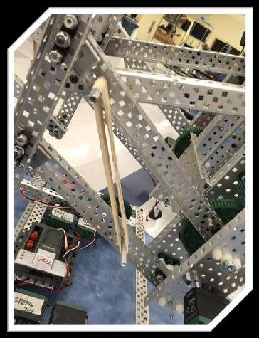
15 Brainstorming The Double Reverse 6-Bar We looked at other robots in our club for inspiration. 80Y s double reverse four bar intrigued us. We brainstormed a new similar design. We analyzed the difference between a six bar and a four bar and found that there was a significant height difference. This difference made us wonder if a double reverse six bar would have the same advantage over a double reverse four bar. We sketched both double reverse Six Bars and double reverse four bars to analyze the difference. The height difference was very evident when two sketches were drawn side by side. The double reverse six bar has a large height advantage. Because of this we decided to build a double reverse 6-bar. 14


16 Designing Designing the Double Reverse Six Bar When designing the double reverse Six Bar, we created a layered drawing. This drawing broke the design up into four distinct layers this helps us build and test whether the components will interfere with each other. The details also help us streamline the building process and quickly assemble the arm. The layers are all depicted in the pictures on the right. The design will use both high strength motors and high strength gears to ensure the lift is durable. The entire lift is made from Aluminum to ensure it is light enough to lift. We designed one tower and planned on building two. The second tower was a perfect mirror image of the first one. The two towers would be connected with c-channel support bars and a sync shaft After we were done designing, we gathered materials and prepared to build. 15


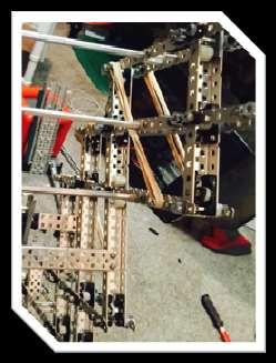
17 Building the Lift 16
18 Failure and Physics After constructing the double reverse 6-bar, we tested it. We ran the motors and the robot began to tip over before it reached maximum height. It tipped so often that we named it Sir Tipsalot. It became a serious problem and we decided to investigate into what makes the robot tip and for that we needed to look at the forces causing the robot to tip over. To do this, we started by drawing an Free body Diagram of the robot s center of gravity. That diagram is below. F g is the Force of gravity of the robot. F g = mg (m is robot s mass, g is acceleration due to gravity). F x is the force in the x direction. F x = ma x (m is mass, a x is acceleration in x direction). S is the distance between the wheel s touch point and the center of gravity. Θ is the angle between the Force of gravity and the line between the center of gravity and the wheel. The dotted lines are normal to line Center of Gravity F connecting the center of x gravity to the touch points. For the robot not 90 - θ to tip, the red component must be θ bigger than the blue θ S one. F g Wheel The red line s magnitude is defined as: F g sin θ = redline. The blue part s magnitude is defined as F x cos θ = blueline. Since the redline s magnitude in for must be greater than the blue line s to avoid tipping, F g sin θ > F x cos θ. After substituting ma x F x, substituting mg in for F g, and solving for acceleration in the x direction, we found our final equation. g tan θ > a x The acceleration due to gravity multiplied by the tangent of the angle from the touch point to the center of gravity must be greater than the acceleration in the X direction for the robot not to tip over. Due to the double reverse 6-bar s weight distribution, the center of gravity constantly moved. The center gravity often hung over the back of the wheels so any acceleration in the x direction would be greater than the tangent of the angle times the acceleration due to gravity. Basically, both the design s geometry and weight distribution caused the tipping. The physics revealed that major changes would be needed to prevent tipping After a long debate, we decided to redesign a new mechanism because we thought the problems were too severe to fix without scrapping the whole thing. 17

19 The PantaGraph THE PANTAGRAPH 18


20 The Problem Since our double reverse six bar was a complete failure, we needed to redesign a lift system. We reanalyzed the game and redefined our problem. Rob and Miranda noticed that this year s game Skyrise closely resembled an older game, Gateway. There was a similar scoring method, de-scoring rules, post owning bonus points and goal heights. The fields also had a large pile of game elements in a pyramid shape with other elements scattered around the field. There are a few differences between the two games but the methods of scoring points are fundamentally the same. Since the two games are so similar, examining previous successful gateway robots could help us with our design for Skyrise. Our team had not been to a Skyrise competition at this point in the season but Rob and Miranda were very experienced when it came to Gateway. Keeping the game similarity in mind, we redefined the problem. Updated Problem Statement: We must create a lifting mechanism inspired by Gateway to lift game elements onto the various sized posts without tipping over. 19
21 Rules and Parameters. Size Requirement Specification: The robot must be no larger than 18in by 18in by 18in large The arm can be no larger than 14 by 18 by 18. Testing Method: The sizing tool will be used to test the final arm design and any concept models in Autodesk Inventor will be measured before fabrication. Why? Robot Rule R4 constrains the dimensions. The current base also constrains the dimensions of the arm. The height of base is four inches tall. To comply with rule R4 we must have a lift no larger than 14 inches. Height requirement Specification: The lift must be able to reach all posts and must be high enough to successfully score on all the goals WITHOUT tipping over. Testing Method: A tape measure will be used to measure the final design and all concept models will be measured. The final design will be placed on a field and will attempt to score goals. Why? Since the highest goal is 47 inches tall and the cubes are 8 in tall so the lift must have a reach of 55 inches because to lift the cube on top of the goal, the bottom of the cube must be higher than the top of the highest post. 20


22 21
23 Design Constraint Specification: The robot must be inspired by a mechanism used in the game Gateway. Testing Method: We will examine pictures of gateway robots and improve upon the designs from those robots. Why? Our old mechanism was inspired by a toss up robot and toss up was a very different game with much lower goals. The highest gateway goal was 30in tall. Robots for gateway were designed to reach lofty heights. Any extremely successful design from that game should also potentially be successful in Skyrise. We will not copy the mechanism but we will take inspiration only from gateway designs. Stability requirement Specification: The lift must be stable and have a stable center of gravity. A lift where the center of gravity only moves up and down and does not shift left or right would be ideal. Any particularly back heavy designs like the double reverse 6-bar are not acceptable. Testing Method: To test this we will run the robot and see if it tips over and we will guestimate the center of gravity in any of our designs. Why? We want our lift to refrain from tipping over during game play and we do not want it to fail like Sir Tipsalot failed. We want to incorporate the stability into the overall design because it is a crucial aspect. 22


24 Design and Inspiration Our inspiration Three years ago Miranda designed and built a special scissor lift for Gateway. The final height of her design was an astonishing 5ft tall. Her original inspiration for the design was an episode of the show How its Made. On the show, collapsible room dividers were created using a special scissor lift called a pantograph. Miranda was inspired by this design and created the gigantic robot seen in the picture on the bottom right. Her robot was taller than she was. That robot competed in Gateway and attended the Vex Robotics World Championship in It was a surprisingly stable design. It was very effective at playing Gateway and won multiple tournaments in the Pennsylvania region. We decided an improved pantograph would be the best lift solution due to its stability and success in Gateway. 23


25 Improving the Old Design We kept the main structural elements from the old lift design but we improved the lifting mechanism by making it lighter and more compact. The top pictures shows the old robot lifting mechanism. It was spaced out and primarily made from steel. The sync shaft required many 12 tooth gears and was fairly inefficient. The new lift design is narrower and lighter. Unlike the old deign, the new one uses the new style of linear slides to propel the tracks up and down. The new style is lighter because only one of the two components is steel. The new lift is also more compact because instead of a sync shaft, it uses two 60- tooth gears to synchronize the motors. The final rack design also was longer and allowed a greater range of scissor lift motion. 24


26 Build Montage 25


27 26


28 Failures and Struggles Failure The design was tall, refused to tip over and was fairly light but it ultimately failed. The top levels of the scissor did not extend upwards at the same rate. This led to one side raising higher than the other. The top was tilted and unstable. Instead of a tipping problem we had a tilting problem. On top of the tilt, some of the bars in the lower sections began to bend. We tried multiple solutions to stop the bending and tilting. All failed. Eventually we removed over half of the scissor levels severely shortening the reach. We eliminated the bending but we limited our reach to the short goals Our lift was almost identical to the one Miranda built in Gateway. We wondered why our lift failed because the previous design worked perfectly. 27

29 Investigating Material Properties After the failure of our lift, we decided to examine the pictures of Miranda s old Scissor to see if there were any differences between the two. We observed that the metal Miranda s scissor was constructed from was slightly different than our current Aluminum. We closely examined the aluminum in our box and realized there were two distinct types of aluminum: old aluminum and new aluminum. Our scissor was made from the new aluminum but the Gateway scissor was made from the old Aluminum. We investigated the material properties of the New and old Aluminum by preforming tensile strength tests on a special material properties testing machine found in Miranda and Sarah s high school. They tested the tensile strength of old and new Aluminum. The stress strain curve is displayed below: 28
30 29
31 A Stress Strain curve shows the elongation when a part is subjected to a force. It We analyzed the stress strain curve for the yield strengths, the ultimate strengths, the strains at break and the strain at the yield. We compared those points on both the old and New Aluminum Alloys. These results are displayed in the table below. New Aluminum Old Aluminum % difference Yield Strength (ksi) % Ultimate Strength (ksi) % Strain at Break (in/in) % Strain at Yield (in/in) % It is plain to see that the only advantage New Aluminum has over old Aluminum is that it stretches 51% longer before it breaks. Otherwise, the old Aluminum preformed much better than the new. Could this be the source of our failure? We decided to investigate and discover the old aluminum s exact alloy. Based on the published alloy for the new Aluminum (5052 H32) we determined that the old aluminum is 5086 H32. A table displaying the differences between the two is below. Aluminum Alloy Price Amount Yield Stress (psi) % diff Ultimate Stress (psi) 5052 H32 Aluminum Sheet $ x1 sheet H32 Aluminum sheet $ x1 sheet % So there is a distinct difference between the old and new Aluminum. We found the old aluminum is superior to the new. Knowing this we found bars of old aluminum and replaced the top half of our scissor with the Old bars. Combining the new bars with The old bars allowed us to build more levels and achieve greater heights. Now our robot is five skyrises tall. It still was not tall enough to achieve all our goals, but it was a start. 30

32 The Skyrise Claw THE SKYRISE CLAW 31

33 The Problem After we built a lift, we needed a mechanism to score. We decided to focus on building Skyrises because Skyrises seemed the best possible way to efficiently score the most points. Each Skyrise section is worth 4 points and each cube on the Skyrise is worth 4 points. Since the Skyrise is close to the starting tile, building Skyrises is an easy way to score points in the autonomous period. This is important to us because there is a 10 point autonomous point bonus and that bonus can sway the match significantly. Our current lift configuration is perfect for Skyrise building. The linear motion of the scissor lift is perfect for nesting the Skyrises and for removing them from the Skyrise holders. This is because the front of the scissor lift travels up and down within the same plane. This keeps any front mechanism from traveling forwards and backwards. In other lift designs like 8-bar linkages, the manipulator travels forwards when raised. The arm travels in an arc instead of a straight line. The scissor travels in a line making it perfect for delivering Skyrise sections to the base no matter what the height. The current base design does not move in any direction. This is a problem for Skyrise building because it would need to turn to move a Skyrise from the holder to the base. This problem can be avoided if our grasping mechanism can swing and reach both the Skyrise and the holder without moving the base PROBLEM STATEMENT: After analyzing the scoring opportunities we decided our grasper must score Skyrises while the base remains stationary. 32
34 Relevant Parameters Size requirement. Specification: The robot must be no larger than 18in by 18in by 18in large The manipulator can be no larger than 18 long by 5 wide by 12 tall Testing Method: The sizing tool will be used to test the final arm design and any concept models will be measured before fabrication. Why? Robot Rule R4 constrains the dimensions. The current base and arm also constrain the dimensions of the manipulator The width of base is 14 in wide. To comply with the rule the manipulator must stick out no farther than 4 inches past the edge of the base Reach requirement Specification: The lift must be able to reach all posts and must be high enough to successfully score on all the goals WITHOUT tipping over. Testing Method: A tape measure will be used to measure the final design and all concept models will be measured. The final design will be placed on a field and will attempt to score goals. Why? Since the highest goal is 47 inches tall and the cubes are 8 in tall so the lift must have a reach of 55 inches because to lift the cube on top of the goal, the bottom of the cube must be higher than the top of the highest post. Grasping requirement Specification: The claw must be at least 3.5 inches wide and long. Testing Method: A tape measure will be used to measure the dimensions. All to scale drawings and models must meet this specification. Why? The largest Skyrise piece section has a diameter of 3.13 in. We need our claw to be a bit larger than that to accommodate for any misalignment in gives us a bit of wiggle room when grasping the sections 33


35 Brainstorming Brainstorming the Claw We brainstormed a swinging skyrise arm design with a linear slide grasper and claw made from forty fie degree angle brackets. The whole claw will be mounted on the scissor. A motor with a 12 tooth gear will turn the 36 tooth gear connected to the end of the manipulator. This will sweep the sweep back and forth and allow us to pick up skyrises with ease. The liner slide grasping mechanism ensures the skyrise is grabbed and will not tilt in transit. It also allow one side of the grasper to remain open. This will make clamping onto the skyrises easier. The drawings to the right show each claw layer in detail. 34


36 Building the Skyrise Sweeper 35

37 The New Scissor Lift THE NEW SCISSOR 36

38 The New Scissor After successfully winning the design Award at the Pennslyvania State championships, we decided to redesign the scissor lift. We used the same criteria and problem statement as before only this time we tried to think outside the box. We decided to design a c- channel 1x25 hybrid scissor lift because we believed a hybrid lift would be more stable than any other design. We also used bering blocks and lock nuts at each connection point to stabilize the lift. We designed an screwheadless bearing block system to minimize interference while lifting. It involves wedging two Bering blocks, piece of plastic nut bar and a spacer between the inside walls of a c-channel. A standoff coupler is screwed through the entire bar. This creates a solid Bering block connection with no screw heads on the outside. We created this lift and built an entirely new (yet almost identical) robot around it. 37


39 Building the New Scissor 38
40 39
Gael Force FRC Team 126
 Gael Force FRC Team 126 2018 FIRST Robotics Competition 2018 Robot Information and Specs Judges Information Packet Gael Force is proof that one team from a small town can have an incredible impact on many
VEX Adjustable C-Channel
 Miraleste Intermediate School Robotics MEME Team 7035M Miraleste Intermediate School STEM Program (Rancho Palos Verdes, CA) VEX Adjustable C-Channel 2019 Make It Real CAD Engineering Challenge Shirzad
BROWNCOATS Team 7842 Engineering Notebook - Rover Ruckus
 Date Location Start Time End Time Week # September 14, 2018 AvaLAN Wireless 2:00 p.m. 6:00 p.m. 2 Meeting Goals: Discuss Brainstorming Ideas, Continue assembly of drive train Team Members in Attendance:
This document will provide detailed specifications, BOM information, and assembly instructions for the Official Competition Field.
 This document will provide detailed specifications, BOM information, and assembly instructions for the Official Field. Teams who do not need an official field should refer to the separate low-cost field
Critical Design Review
 1 Critical Design Review 2 Table Of Contents 1.0 Introduction 3 1.2 Purpose 4 1.3 Scope 5 1.4 Definitions and Acronyms 6 1.5 References 7 2.0 Overall Description 8 2.1 Product Perspective 9 2.2 Product
Requirements Document. Gateway <04/17/12> Coaches: < Renée Andrews, Michael Ehrenfreid, Bryan Rich >
 Requirements Document Gateway Coaches: < Renée Andrews, Michael Ehrenfreid, Bryan Rich > Students: < Teja Aluru, Lane Baumgarten, Peter Cooper, Rob Giometti, David Kading, Shane Mathias, Russell
VEX IQ Challenge - Highrise. Field Appendix. Page 1. Copyright VEX Robotics Inc. v
 Field Appendix Page 1 Introduction This document will provide detailed specifications, a bill of materials (BOM), and assembly instructions for the Official Competition Field. Please note that this field
Strategic Design. Michael Corsetto
 Strategic Design Michael Corsetto Training Golden Rule #3 Steal From The Best, Invent The Rest Get Team familiar with past games and robots Games will often be similar to past games Examples: 2004, 2010,
Students will design, program, and build a robot vehicle to traverse a maze in 30 seconds without touching any sidewalls or going out of bounds.
 Overview Challenge Students will design, program, and build a robot vehicle to traverse a maze in 30 seconds without touching any sidewalls or going out of bounds. Materials Needed One of these sets: TETRIX
MECH 4860 (Senior Project Design) Meeting Minutes
 Meeting Minutes") Date: September 9 th, 2014 Attendance: David, Allison, Yapah, Persaud, Jeffrey, Josel De la Cruz and Ronald We all reviewed the parts necessary to running a successful meeting. o Meeting leader, note taker,
Date: September 9 th, 2014 Attendance: David, Allison, Yapah, Persaud, Jeffrey, Josel De la Cruz and Ronald We all reviewed the parts necessary to running a successful meeting. o Meeting leader, note taker,
Medb ot. Medbot. Learn about robot behaviors as you transport medicine in a hospital with Medbot!
 Medb ot Medbot Learn about robot behaviors as you transport medicine in a hospital with Medbot! Seek Discover new hands-on builds and programming opportunities to further your understanding of a subject
the complete parts reference bricks
 the complete parts reference Here s a detailed overview of all the pieces in your LEGO BOOST kit. You can also identify LEGO elements precisely by their LEGO ID, which is printed on the LEGO BOOST test
Sample Questions for the Engineering Module
 Sample Questions for the Engineering Module Subtest Formalising Technical Interrelationships In the subtest "Formalising Technical Interrelationships," you are to transfer technical or scientific facts
Senior Design Project
 University of Tennessee, Knoxville Trace: Tennessee Research and Creative Exchange University of Tennessee Honors Thesis Projects University of Tennessee Honors Program 5-2016 Senior Design Project Lee
3" LATHE THREAD CUTTING ATTACHMENT
 3" LATHE THREAD CUTTING ATTACHMENT P/N 3 AN INTRODUCTION TO THREAD CUTTING IN THE REAL WORLD After designing and putting the enclosed screw cutting attachment into production, we sat down and started reading
A vibration is one back-and-forth motion.
 Basic Skills Students who go to the park without mastering the following skills have difficulty completing the ride worksheets in the next section. To have a successful physics day experience at the amusement
PoeBot Building Instructions CCISD. Upper Gripper. Lower Gripper/ Spatula. PoeBot Instructions PLTW. Clear Creek ISD
 Upper Gripper Lower Gripper/ Spatula PoeBot Instructions PLTW Clear Creek ISD 1. Chasis Construction (Split Group with half starting Step 1 and half starting Step 13.) Note: These flat bearings are offset
Deriving Consistency from LEGOs
 Deriving Consistency from LEGOs What we have learned in 6 years of FLL and 7 years of Lego Robotics by Austin and Travis Schuh 1 2006 Austin and Travis Schuh, all rights reserved Objectives Basic Building
This document will provide detailed specifications and a bill of materials (BOM) for the Official Competition Field.
 for the Official Competition Field.") Introduction This document will provide detailed specifications and a bill of materials (BOM) for the Official Competition Field. Please note that this field utilizes the VEX IQ Challenge Full Field Perimeter
Introduction This document will provide detailed specifications and a bill of materials (BOM) for the Official Competition Field. Please note that this field utilizes the VEX IQ Challenge Full Field Perimeter
This document will provide detailed specifications, BOM information, and assembly instructions for the Official Competition Field.
 This document will provide detailed specifications, BOM information, and assembly instructions for the Official Competition Field. Teams who do not need an official field should refer to the separate low-cost
1/2/2016. Lecture Slides. Screws, Fasteners, and the Design of Nonpermanent Joints. Reasons for Non-permanent Fasteners
 Lecture Slides Screws, Fasteners, and the Design of Nonpermanent Joints Reasons for Non-permanent Fasteners Field assembly Disassembly Maintenance Adjustment 1 Introduction There are two distinct uses
Depending on the size you ordered you will have either 5 Foot sections which will build the 10 Foot frame or 6 Foot sections which will build the 12
 XL Quilting Frame 1 Depending on the size you ordered you will have either 5 Foot sections which will build the 10 Foot frame or 6 Foot sections which will build the 12 Foot frame Printed 2 June 2014 Updated
MODEL T28000 HEAVY-DUTY MOBILE BASE INSTRUCTIONS
 MODEL T28000 HEAVY-DUTY MOBILE BASE INSTRUCTIONS For questions or help with this product contact Tech Support at (570) 546-9663 or techsupport@grizzly.com Introduction Your new Model T28000 Heavy-Duty
MM340 Installation Instructions IMPORTANT SAFETY INSTRUCTIONS - SAVE THESE INSTRUCTIONS
 MM30 Installation Instructions IMPORTANT SAFETY INSTRUCTIONS - SAVE THESE INSTRUCTIONS Please read this entire manual before you begin. Do not unpack any contents until you verify all requirements on PAGE.
The Phoenix. Professional Quilting Frame. Copyright January 1, 2016 Jim M. Bagley, GraceWood, Inc (Reproduction Prohibited) Version 2.
 Version 2.") The Phoenix Professional Quilting Frame Copyright January 1, 2016 Jim M. Bagley, GraceWood, Inc (Reproduction Prohibited) Version 2.1 1 The Phoenix Professional Quilting Frame Parts List Box 1...3 Box
The Phoenix Professional Quilting Frame Copyright January 1, 2016 Jim M. Bagley, GraceWood, Inc (Reproduction Prohibited) Version 2.1 1 The Phoenix Professional Quilting Frame Parts List Box 1...3 Box
Ultimatum. Robotics Unit Lesson 5. Overview
 Robotics Unit Lesson 5 Ultimatum Overview In this final challenge the students will deploy their TETRIX rescue robot up the mountain to rescue the stranded mountain climbers. First the rescue robot has
Durham Woodworking Club. January 25, 2016
 Durham Woodworking Club January 25, 2016 The drill press has primarily been a metal working machine since its first incarnation. The purpose of the modern day drill press has been to provide woodworkers
Fracture Packaging Report
 Fracture Packaging Report PKG4008 Distribution and Transport Packaging April 20 th, 2016 Team Members Group 3 Charles Buckley Luis Chong Bryce Reeves Mary Regan Maxwell Sanders Lucy Toman Table of Contents
4) Drive Mechanisms. Techno_Isel H830 Catalog
 Drive Mechanisms. Techno_Isel H830 Catalog") 4) Drive Mechanisms This section will introduce most of the more common types of drive mechanisms found in linear motion machinery. Ideally, a drive system should not support any loads, with all the loads
4) Drive Mechanisms This section will introduce most of the more common types of drive mechanisms found in linear motion machinery. Ideally, a drive system should not support any loads, with all the loads
Operating Instructions For Lockformer Button Punch Flanger
 Capacity: 20 to 28 Gauge Galvanize Operating Instructions For Lockformer Button Punch Flanger To satisfactorily form the 90º button punch flange on light gauge materials, it was necessary to form the metal
MM750 Installation Instructions
 MM750 Installation Instructions IMPORTANT SAFETY INSTRUCTIONS - SAVE THESE INSTRUCTIONS Please read this entire manual before you begin. Do not unpack any contents until you verify all requirements on
Agave Standard Series
 Mailing Address: 033 San Elijo Ave, #464 Cardiff, CA 9007 619.708.917 619.330.88 fax info@agaveiron.com www.agaveiron.com Agave Standard Series Flat Track Hardware Systems General Information and Installation
E4-WM5-Y525A00 MOUNTING INSTRUCTION
 RAM 2500/3500 4WD B8 5100 (Dual Steering Damper Kit) The installation of these steering dampers must be performed only by experienced and qualified personnel. Read and follow the installation instructions
Log Hauler. Senior Design Project. Department of Mechanical Engineering Trevor Kline 4/19/2011
 Log Hauler Senior Design Project Department of Mechanical Engineering Trevor Kline 4/19/2011 Table of Contents BACKGROUND:... 3 INSPIRATION:... 3 PROPOSAL AND REQUIREMENTS:... 4 DESIGN:... 4 LOG SIZE:...
Drilling. Drilling is the operation of producing circular hole in the work-piece by using a rotating cutter called DRILL.
 Drilling Drilling is the operation of producing circular hole in the work-piece by using a rotating cutter called DRILL. The machine used for drilling is called drilling machine. The drilling operation
MM540 Installation Instructions IMPORTANT SAFETY INSTRUCTIONS - SAVE THESE INSTRUCTIONS
 MM50 Installation Instructions IMPORTANT SAFETY INSTRUCTIONS - SAVE THESE INSTRUCTIONS Please read this entire manual before you begin. Do not unpack any contents until you verify all requirements on PAGE.
Determining the Relationship Between the Range and Initial Velocity of an Object Moving in Projectile Motion
 Determining the Relationship Between the Range and Initial Velocity of an Object Moving in Projectile Motion Sadaf Fatima, Wendy Mixaynath October 07, 2011 ABSTRACT A small, spherical object (bearing ball)
Figure 1. Overall Picture
 Jormungand, an Autonomous Robotic Snake Charles W. Eno, Dr. A. Antonio Arroyo Machine Intelligence Laboratory University of Florida Department of Electrical Engineering 1. Introduction In the Intelligent
Catapult Engineering
 With support from Oxfordshire County Council, Science Oxford is pleased to present; Catapult Engineering The Physics of Siege Weapons STEM Club Resource Pack Introduction: Catapult engineering involves
CROWNARC. ARC Integrated Systems
 CROWNARC Screw your new CROWNARC to 2 pieces of 2 x 4 using the 4 holes. Then, mount the 2 x 4 s to the wall. You ll have best control when the CROWNARC is just above waist level. To crown a bow: Lay a
Force multipliers and speed multipliers Machines can make work easier by reducing the amount of force necessary to move an object or increasing the
 MACHINES A machine is a device that makes work easier by transmitting or transforming energy. They have been used since ancient times to help people move heavy objects, bring substances like water from
A NOVEL PASSIVE ROBOTIC TOOL INTERFACE
 A NOVEL PASSIVE ROBOTIC TOOL INTERFACE Paul Roberts (1) (1) MDA, 9445 Airport Road, Brampton, ON, Canada, L6S 4J3, paul.roberts@mdacorporation.com ABSTRACT The increased capability of space robotics has
MOVENTO. The Evolution of Motion
 The Evolution of Motion is the latest advancement in concealed runner technology. It brings together all of the features, innovations and benefits that Blum has developed since first manufacturing drawer
Sound Automata. Category: Physics: Force & Motion; Sound & Waves. Type: Make & Take. Rough Parts List: Tools List: Video:
 Sound Automata Category: Physics: Force & Motion; Sound & Waves Type: Make & Take Rough Parts List: 2 Clear plastic cups, large 2 Bamboo skewers 2 Straws 1 Sheet of cardboard or foam core 1 Bottle cap
Screw. Introduction This Rokenbok STEM-Maker lesson will use the following steps to learn about the screw. Learning Objectives. Resources.
 Screw Progression: Applications in Design & Engineering - Section 6 Curriculum Packet v2.0 Introduction This Rokenbok STEM-Maker lesson will use the following steps to learn about the screw. 1. Learn 2.
FLL Coaches Clinic Chassis and Attachments. Patrick R. Michaud
 FLL Coaches Clinic Chassis and Attachments Patrick R. Michaud pmichaud@pobox.com Erik Jonsson School of Engineering and Computer Science University of Texas at Dallas September 23, 2017 Presentation Outline
BHJ Products, Inc. Parts List & Instructions
 Product Name: Lifter-Tru Kit for Ford Windsor & SVO Small Block V8 Page 1 of 5 Kit Contents: 2x End Plates 2x 5/8 Threaded Adjustment Sleeves 1x Front Angle Bracket 2x 5/8 Adjustment Sleeve Spacers * 1x
Reversing Gear. Shay Reversing Gear
 Shay Nelson Riedel Nelson@NelsonsLocomotive.com Initial: 9/23/03 Last Revised: 06/05/2004 The reversing gear is another one of those pieces I've been putting off. The reason for the postponement was that
Inclined Plane, Wedge, Screw PRE-TEST. DIRECTIONS: Answer the following questions in the space provided.
 1 PRE-TEST DIRECTIONS: Answer the following questions in the space provided. 1. Name the six simple machines. 2. Describe how a wedge is related to an inclined plane? 3. Give a definition for the term
DESIGN AND FABRICATION OF BOX TRANSPORT MECHANISM
 DESIGN AND FABRICATION OF BOX TRANSPORT MECHANISM Siva Krishna Y 1 and Moulali Sk 2 1 Assistant professor, Mechanical Engineering Department, Sree Venkateswara College of Engineering, Nellore, A.P, India.
Testing of the FE Walking Robot
 TESTING OF THE FE WALKING ROBOT MAY 2006 1 Testing of the FE Walking Robot Elianna R Weyer, May 2006 for MAE 429, fall 2005, 3 credits erw26@cornell.edu I. ABSTRACT This paper documents the method and
Product design: Structural systems
 Product design: Structural systems Tension and compression The arch bridge and the aerial ropeway in the panels below were designed to resist specific loads and forces. The arch has to resist the load
AUTOMATIC ADVANCE MANUAL
 AUTOMATIC ADVANCE MANUAL AVL Looms, Inc. 3851 Morrow Lane, Suite #9 Chico, CA 95928-8305 530 893-4915 530 893-1372 fax # info@avlusa.com www.avlusa.com Copyright 2009 TABLE OF CONTENTS Page # I. Parts.........................
Accessories for the Model 920 Lapping and Polishing Machine
 Accessories for the Model 920 Lapping and Machine Applications Laboratory Report Introduction polishing is a common practice in many materials preparation laboratories. Instrumentation for materials processing
Chassis & Attachments 101. Part 1: Chassis Overview
 Chassis & Attachments 101 Part 1: Chassis Overview 2017 1 Introductions Rest rooms location. Food and Drink. Cell phones. Today presentation available at: http://www.roboplex.org/fll 2 What can be used
Field Specs & Assembly Instructions
 VEX Robotics Sack Attack Field Specs & Assembly Instructions 4/13/2012 Copyright 2012. VEX Robotics Inc. VEX Robotics Sack Attack A Introduction A P P E N D I X Game Field This document will provide detailed
Brochure Includes: Set-up Instructions Operating Instructions Parts List Fundamentals of Drill Sharpening. Patent 3,952,459
 Patent 3,952,459 Brochure Includes: Set-up Instructions Operating Instructions Parts List Fundamentals of Drill Sharpening Accurately Sharpens most drills bits. Now, with this one low-cost, simple machine,
Step 1: Gather your parts!
 Step 1: Gather your parts! Show All Items The #mearm was designed with economy in mind. It is understood that laser cutters aren't the most common tools but there are more of them out there now than
Warnings. Description. Prior to Installation Tools Needed
 Warnings Failure to act in accordance with the following may result in death or personal injury. The JT Strong Arm Stabilizer System is intended to eliminate chassis movement in travel trailers and fifth
GC-1032 Metal Detector OWNER S MANUAL
 GC-1032 Metal Detector OWNER S MANUAL 1 With your GC-1032 metal detector, you can hunt for coins, relics, jewelry, gold, and silver just about anywhere. The detector comes with high sensitivity and strong
High Rise Sit-Stand Desk Converter
 High Rise Sit-Stand Desk Converter Assembly Instructions for Model DC350 Patent No. 9,332,839 PRE-ASSEMBLY Please read all instructions before beginning assembly. We strongly recommend you watch the video
AM8 Printer A metal frame for your Anet A8 By Pheneeny v1.0 April 20, 2017
 AM8 Printer A metal frame for your Anet A8 By Pheneeny v1.0 April 20, 2017 Please read this entire document before printing parts or building this frame Disclaimer: This guide is for informational purposes
Motorized Balancing Toy
 Motorized Balancing Toy Category: Physics: Force and Motion, Electricity Type: Make & Take Rough Parts List: 1 Coat hanger 1 Motor 2 Electrical Wire 1 AA battery 1 Wide rubber band 1 Block of wood 1 Plastic
Chassis & Attachments 101. Chassis Overview
 Chassis & Attachments 101 Chassis Overview 2016 1 Introductions Rest rooms location. Food and Drink: Complementary bottled water. Snacks available for purchase from UME FTC teams. Cell phones. Today presentation
BLACK HOLE DUST CATCHER Assembly and Installation Instructions
 BLACK HOLE DUST CATCHER Assembly and Installation Instructions By: Contents 1. Heavy Duty Aluminum track 1 each 2. Large heavy duty knobs 2 each 3. ¼ x 20 x 1 ¾ T bolts 4 each 4. ¼ x 20 nuts and washers
Wood Duck Nest Box Design & Assembly Directions
 Wood Duck Nest Box Design & Assembly Directions Instructions, Illustrations & Photos Courtesy of MWDI and Scott Jasion, Harford County Chapter, Ducks Unlimited Side door opening design for easy mounting
8.10 Drill Grinding Device
 8.10 Drill Grinding Device Special Accessories 1. Introduction Device can accurately grind precision drill and tools, this drill grinding machine system consists of a motor and grinding wheel head composed
TOOL LIST FOR TAILGATE HIDDEN LATCH & LINK ASSY FOR FORD FLARESIDE TRUCKS
 TOOL LIST FOR TAILGATE HIDDEN LATCH & LINK ASSY FOR 53-87 FORD FLARESIDE TRUCKS Vise Grip Clamps C-clamps Sharpie Marker Ball Peen Hammer Center Punch 3/8 or 1/2 Drill 5/32, 7/32, 9/32, and 3/8 Drill Bits
Obtained from Omarshauntedtrail.com
 DaveintheGrave's Halloween Props Animated Crawling Skeleton Build a life-size skeleton torso that realistically crawls across the lawn one arm at a time. 1. Motor Base and Linkage Assembly BASE - I used
Legacy Upgraded Junior Gentlemen s Pen Kit
 Description: The Upgraded Junior Gentlemen s model is a classic style pen which is easy to turn and uses a Roller Ball Refill which is highly desirable among pen enthusiasts The Upgraded Junior Gentlemen
Bound and Determined:
 Think You Don t Have Time to Create Beautiful Quilts? From quick-quilt adaptations of classic patterns to fun, fresh novelty designs, McCall s Quick Quilts provides you with a treasury of time- and effort-saving
Appendix E VEX U. VEX Robotics Competition Turning Point Appendix E
 Appendix E VEX U Introduction We are thrilled to continue the exciting VEX U program for another year, with some new twists for the 2018-2019 season. While many colleges and universities already use the
c. Pins, bolts, and retaining rings b. Washers, locking nuts, and rivets
 62 20 HW 8: Fasteners / Force, Pressure, Density Mechanical Systems DUE Mon, 11/21/16 Start of class Check link on website for helpful fastener information Please use a scantron. Material is based primarily
MantelMount. TM1A Installation Instructions IMPORTANT SAFETY INSTRUCTIONS - SAVE THESE INSTRUCTIONS
 MantelMount TMA Installation Instructions IMPORTANT SAFETY INSTRUCTIONS - SAVE THESE INSTRUCTIONS TM Thank you for choosing the MantelMount television wall mount. Please read this entire manual before
DP-8 H. H. MØRCH. Instructions. Contents of the packing. Spatial requirements. Mounting the bush
 DP-8 Instructions H. H. MØRCH Contents of the packing In the packing of the tonearm you will find the arm base in which the bearings are encapsulated in a heavy body. This is the link between the moveable
Mechanical System Specifications & Detail Drawings
 Mechanical System & Detail Drawings 1-888-989-1370 www.lundiausa.com RECOM GROUP INC. 449 Borrego Court San Dimas, CA 91773 Phone: (909) 599-1370 Fax: (909) 599-2291 MECHANICAL SYSTEM SPECIFICATIONS All
JARVIS. Model BR-3 Blade Reconditioner ... EQUIPMENT TABLE OF
 - Model BR-3 Blade Reconditioner EQUIPMENT SELECTION.......... Ordering No. TABLE OF CONTENTS............................ Page Model BR-3 (100 mm Blade) 115V/60Hz............ 4011003 220V/50Hz............
OWNER S MANUAL VENDING MACHINE
 OWNER S MANUAL 3 in 1 CANDY / SNACKS GUmbALL / TOY VENDING MACHINE For Assembling and Operating Your New Vending Machine TABLE OF CONTENTS 1. Customer Letter and Helpful Hints..1 Important Advice, Inspecting
FRC TEAM BUILD SEASON DOCUMENTATION MECHANICAL ADVANTAGE FRC littletonrobotics.org
 FRC TEAM 6328 2018 BUILD SEASON DOCUMENTATION MECHANICAL ADVANTAGE FRC 6328 littletonrobotics.org KICKOFF Pre-kickoff breakfast with FRC Team 1058 KICKOFF The team headed up to Southern NH University for
Obtained from Omarshauntedtrail.com
 http://www.scary-terry.com/dancskele/dancskele.htm This is a how-to for making a set of dancing skeletons for your Halloween window display. It uses a pair of cheap, glow-in-the-dark plastic skeletons
SERVICE MANUAL AND PARTSLIST
 SERVICE MANUAL AND PARTSLIST Next 20 CONTENTS WHAT TO DO WHEN... 1~3 SERVICE ACCESS FACE COVER... 4 TOP COVER... 4 BASE COVER... 5 REAR COVER... 6 FRONT COVER... 7 MECHANICAL ADJUSTMENT NEEDLE THREAD TENSION...
MODEL T " HELICAL CUTTERHEAD INSTALLATION INSTRUCTIONS
 MODEL T27696 12" HELICAL CUTTERHEAD INSTALLATION INSTRUCTIONS For questions or help with this product contact Tech Support at (570) 546-9663 or techsupport@grizzly.com Introduction The Model T27696 indexable
9.07 KINEMATICS KIT USERS MANUAL
 9.07 KINEMATICS KIT USERS MANUAL INCLUDED PARTS LIST Standard parts - 1. ground plane enclosure which includes stepper motor with control circuits, press fit motor shaft adaptor, and link attachment plate.
LANDMARK UNIVERSITY, OMU-ARAN
 LANDMARK UNIVERSITY, OMU-ARAN LECTURE NOTE: DRILLING. COLLEGE: COLLEGE OF SCIENCE AND ENGINEERING DEPARTMENT: MECHANICAL ENGINEERING PROGRAMME: MECHANICAL ENGINEERING ENGR. ALIYU, S.J Course code: MCE
001-Component-build. Build the following Contraptor components before assembly:
 001-Component-build Build the following Contraptor components before assembly: http://www.contraptor.org/make-linear-rail-v2#assembly http://www.contraptor.org/make-linear-bearings-v2#assembly http://www.contraptor.org/make-sliding-elements#assembly
Introduction to Engineering Design. Part C College Credit Performance
 Introduction to Engineering Design Final Examination Part C College Credit Performance Spring 2007 Student Name: Date: Class Period: Total Points: /50 49 of 99 Page 1 of 9 DIRECTIONS: Complete each of
PRS Retro Z-Axis Installation
 PRS Retro Z-Axis Installation Page -1- PRS Retro Z-Axis Installation This document is a guide to installing the PRS Retro Z-axis on early ShopBot models. It describes installation for PR models with PK299
Straight Bevel Gears on Phoenix Machines Using Coniflex Tools
 Straight Bevel Gears on Phoenix Machines Using Coniflex Tools Dr. Hermann J. Stadtfeld Vice President Bevel Gear Technology January 2007 The Gleason Works 1000 University Avenue P.O. Box 22970 Rochester,
Installation for Full Size Polaris Ranger Crew Doors
 Installation for Full Size Polaris Ranger Crew Doors Order of Installation: Heater Doors Wiper on to Windshield Windshield Top & Back Panel Note: Most of the steps in these instructions need to be repeated
McKenzie Meyer HC 407, Spring 2017, M 16:00-17:50 June 5, Paper Airplanes
 McKenzie Meyer HC 407, Spring 2017, M 16:00-17:50 June 5, 2017 Paper Airplanes Abstract: As technology is advancing in today s age, more jobs are opening up in the Science, Technology, Engineering, and
Tri- State Consulting Co. Engineering 101 Project # 2 Catapult Design Group #
 Tri- State Consulting Co. Engineering 101 Project # 2 Catapult Design Group # 8 12-03-02 Executive Summary The objective of our second project was to design and construct a catapult, which met certain
Building Tips This model can be built using the following types of adhesives:
 Page 1 Building Tips This model can be built using the following types of adhesives: Epoxy (with or without microballons) Odorless cyanoacrylate (CA) with accelerator UHU Creativ for Styrofoam (or UHU
Roborodentia Robot: Tektronix. Sean Yap Advisor: John Seng California Polytechnic State University, San Luis Obispo June 8th, 2016
 Roborodentia Robot: Tektronix Sean Yap Advisor: John Seng California Polytechnic State University, San Luis Obispo June 8th, 2016 Table of Contents Introduction... 2 Problem Statement... 2 Software...
Instruction Manual X97
 Index Page Technical data... 2 Dimensions... 3 General description... 4 Selection of cutter... 5 Instruction for grinding... 5 Dimensions of bevel... 7 Bevelling angle... 8 Adjustment: Straight edge (Land)...
Measurement and Data: Measurement
 Unit 14 Measurement and Data: Measurement Introduction In this unit, students will learn to directly compare objects by capacity, height, length, and weight. They will describe a container as holding more
BROWNCOATS Team 7842 Engineering Notebook - Rover Ruckus
 Date Location Start Time End Time Week # September 8, 2018 September 9, 2018 Huntsville High School AvaLAN Wireless AvaLAN Wireless 11:00 am 2:30 p.m. 12:00 pm 2:00 pm 4:30 p.m. 4:00 pm 1 Meeting Goals:
Lumber Smith. Assembly Manual. If you are having problems assembling the saw and need assistance, please contact us at:
 Lumber Smith Assembly Manual If you are having problems assembling the saw and need assistance, please contact us at: 804-577-7398 info@lumbersmith.com 1 Step 1 Safety Carefully read the Owners Manual.
A team on the (sky)rise.
rise.") Finding Our Voice A team on the (sky)rise. My team s journey in VEX started freshman year. We were three girls with a rising passion for STEM who had heard about the robotics club on our campus. We went
Finding Our Voice A team on the (sky)rise. My team s journey in VEX started freshman year. We were three girls with a rising passion for STEM who had heard about the robotics club on our campus. We went
Installation Instructions for. Before You Begin TOOLS REQUIRED
 Composite Railing System STEP-BY-STEP Installation Instructions for Spectrum Composite Railing Virtually maintenance free 20-year warranty EverNew Spectrum Railing system is designed to work with a number
HD installation guide
 JANUS INTERNATIONAL 1 866 562 2580 www.janusintl.c o m 1950 1950HD installation guide RIGHT DRIVE END SHOWN LH OPPOSITE LEFT TENSION END SHOWN RH OPPOSITE PUSH-UP OPERATION 1950 1950HD SHOWN A rolling