Step 1: Gather your parts!
|
|
|
- Camron Charles
- 5 years ago
- Views:
Transcription

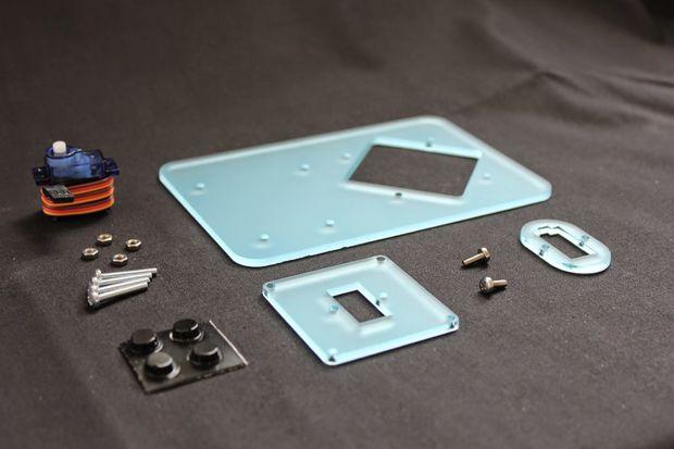
1 Step 1: Gather your parts!
2
3

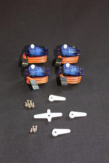
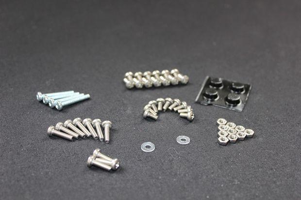
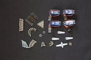
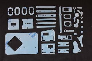
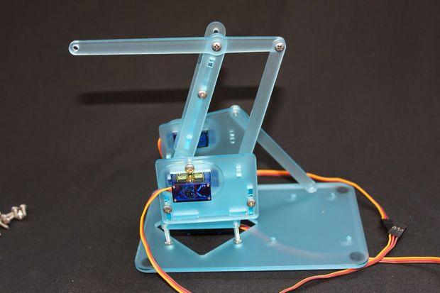
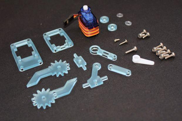
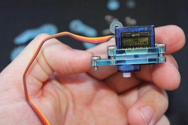
4 Show All Items The #mearm was designed with economy in mind. It is understood that laser cutters aren't the most common tools but there are more of them out there now than ever! First you'll need a set of parts. Grab the dxf and use a cnc mill or laser cutter. For the v0.3 we also had people 3D print the parts. If you get a kit from us or order the parts in acrylic you'll have to remove all of the protective covering. It's not the most fun job but the end result is better! Next you'll need all of the screws and nuts. We use M3 (metric 3mm) standard parts. The number of these to build the latest version is: Nut x 10 6mm x 9 8mm x 12 10mm x 3 12mm x 7 20mm x 4 Washers x 0 (we removed these as nobody ever used them!!) You could no doubt find imperial sized counterparts, as a nation you managed to get a man to the moon with foot pounds per square inch so I'll leave the conversions in your capable hands (in case of residents of Liberia or Myamar ignore the bit about the moon). You'll also need 4 hobby servos. We tend to use the 9g resin gear ones. The metal gear ones with the same footprint are better but they're more expensive.

5 Step 2: Prepare the base!

6

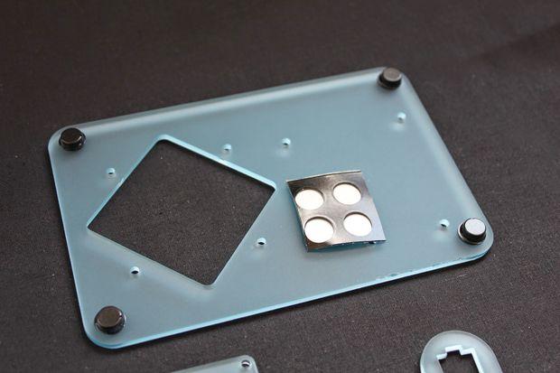
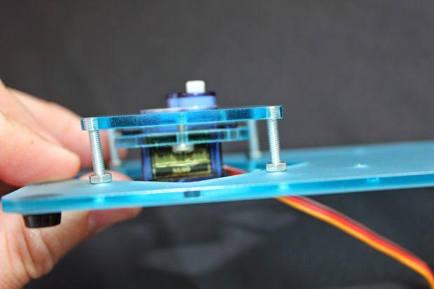
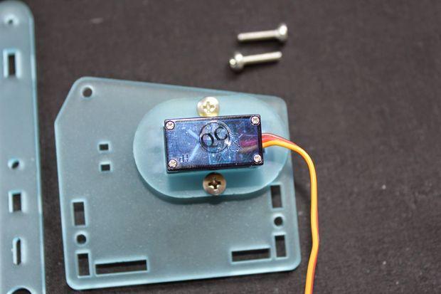
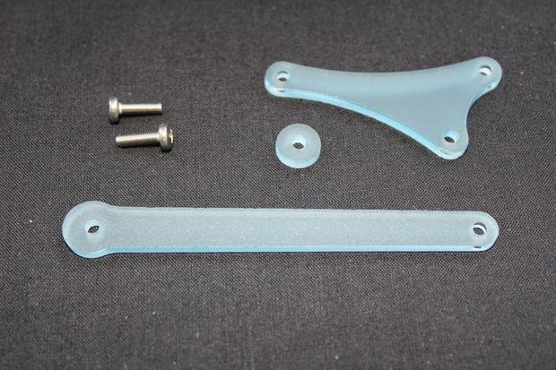
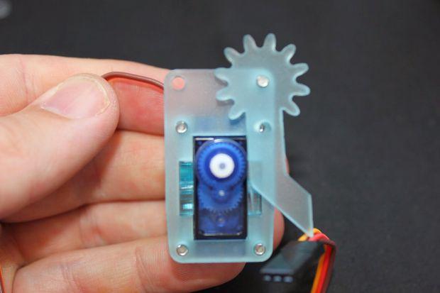
7 I like to get the base built first, it's a bit of a dull first step. But as Mao Tse-tung said "the journey to building a cool robot arm starts with a single, quite dull, step". I may be paraphrasing - but lets just get on with it eh? The parts we use here are: Base largest part you'll have Collar one of the four supplied Square servo mount - fits directly into the hole on the base 4 x 20mm Screws 4 x Nuts 2 x 8mm Screws 4 x Sticky Feet 1 x Servo If you have one of ours with a slick etch on it, you'll want that upper most. That is the top. Otherwise either way is fine. Stick one of the four sticky feet in each of the corners of the base. Then start inserting the 20mm screws into the holes around the large square hole. Now twist the nuts onto the 20mm screws from the top side until you're about half way down.

8 Step 3: Add the square


9
.")

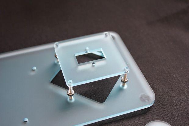
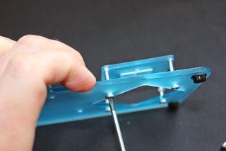
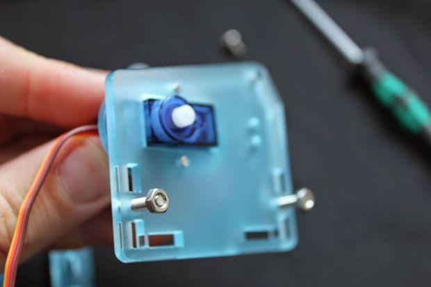
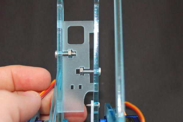
10 Show All Items Next take the square part and place it on top of the 20mm screws, with the rectangle cut out in oriented the same way as the base (as shown in the picture). With the holes on the square part lined up on the screws start to tighten the screws, they should start to self tap into the holes on the square part. Once you have screwed them all so they are flush with the top of the square part we'll move on and tighten the nuts down to the base board as shown. Step 4: Collar the servo
11


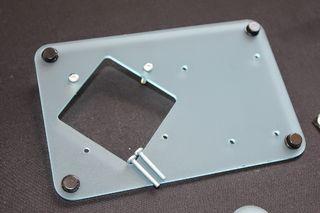
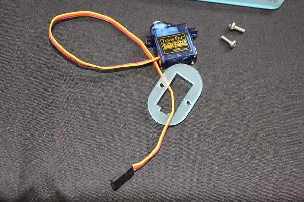
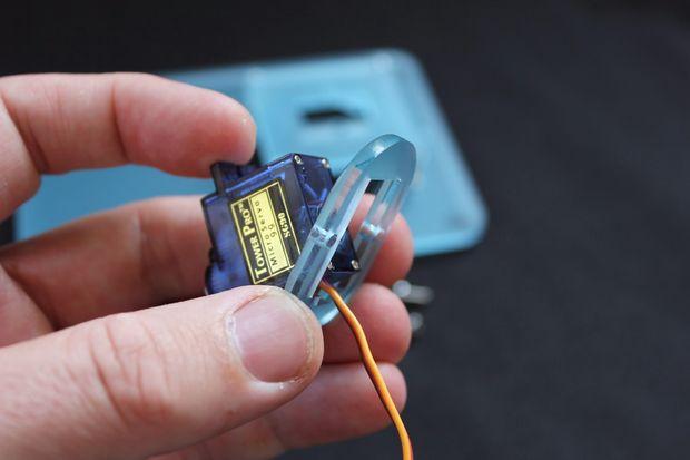
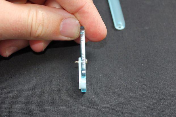
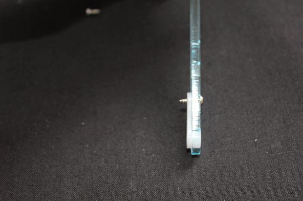
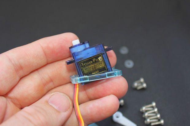
12 We found adding collars to the servos to be the best way to attach them to the arm. This is a technique we'll use a further three times. Thread the wire of the servo through the collar

13 Line the cut out on the collar up with the end of the servo where the wire attaches Bring the collar over the bottom of the servo Push home so it's flat with the flange on the servo Step 5: Attach the collar to the square on the base
14


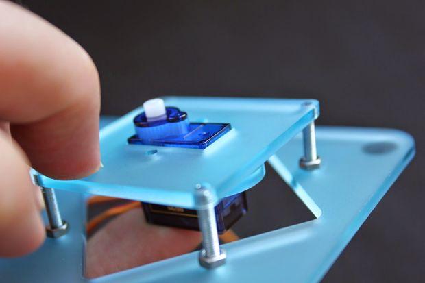
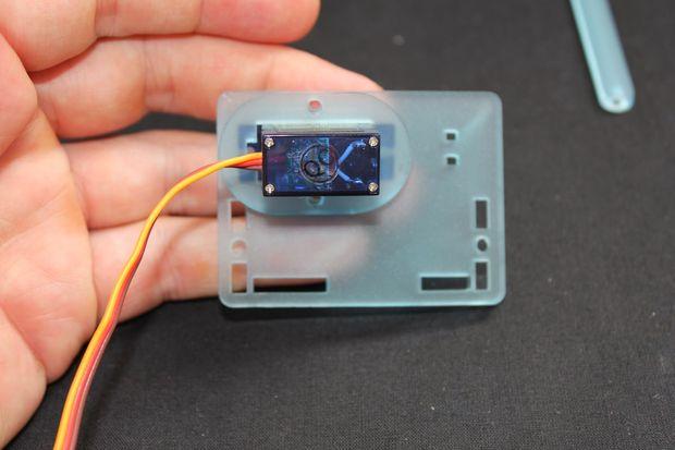
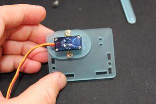
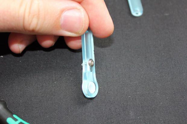
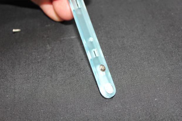
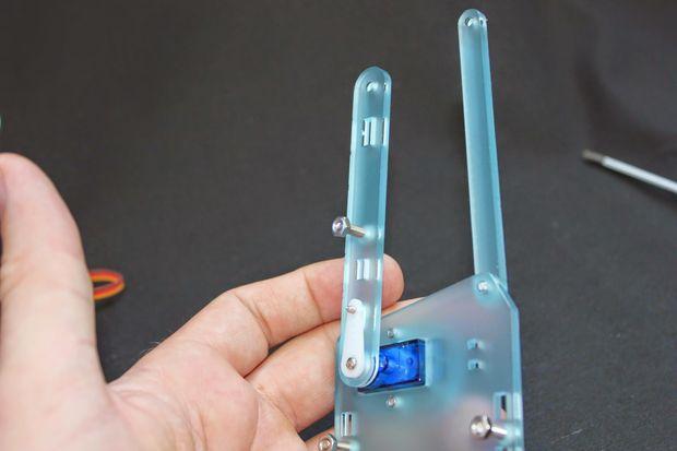
15 Now you've collared your servo line push it through the servo shaped hole on the square part.

16 Insert the two 8mm screws from underneath so they pass through the holes on the collar with little resistance and self tap into the square part. Tighten until the servo is held firmly. Do not over tighten! Did you crack the collar? Told you not to over tighten... But you're not the first so we include a spare servo collar in the kit. Don't do it again! We'll put the base aside for a little while now. Step 6: Construct the left hand side

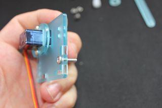
17 Please pay careful attention at this stage. We have keyed the parts to limit the number of possible wrong configurations to exactly one. This actually came in handy when making a larger arm where the orientation of the servos is reversed. However with the standard #mearm you'll want a right handed version as constructed here. That way all of the example code will work! The parts needed here are: 2 x 8mm Screw 2 x 12mm Screw 2 x Nut 1 x 6mm Screw 1 x Collar 1 x Rectangular side part as pictured 1 x Servo mounting arm - the longer of the two you have 1 x Straight lever - you have three of these the same 1 x Servo 1 x Short servo screw 1 x Long servo screw


18 Step 7: Collar the servo and attach
19


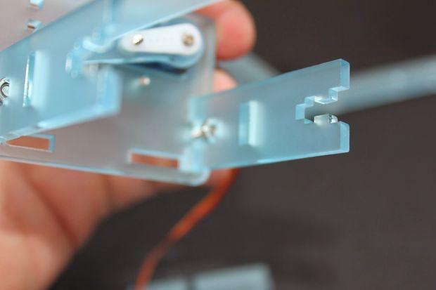
20 Show All Items Thread the servo through like before and screw onto the side piece using the 8mm screws. Pay careful attention to the orientation here. Note the direction of the wire and the way the servo pokes out from the side piece. Now thread the 12mm screws through the round holes that are left and put the nuts on just a half turn. Step 8: Build your first levers
21
 using the long servo screw.")

22 Attach the white plastic servo horn to the servo lever part (as pictured) using the long servo screw. This will poke out the back of the resulting part and is a bit spikey. I trim them off once I'm confident I've put it together correctly!

23 Now attach the long lever to the servo lever, with the screw going through the same side as the servo horn. This is your first moving part. You can adjust it later but it's important that you can move it with very little force. You want to find the right balance between not moving sideways and moving freely. Every bit of force you have to overcome moving these joints is less force you have to lift objects. Keep this in mind for all your moving parts. I'll remind you on the way and you can adjust at the end but it's important. If you find it hard getting the lever to move even with the screw slackened off a little just try moving the joint a couple of times. We tend to cut them so the joints are snug. It should loosen up with that extra movement. It's also possible that the screw may have cut off centre and the joint is angled. In this case just remove it, hold the parts together and screw in again. These joints will allow you about 6 or 7 cycles of construction and destruction! Step 9: Attach lever and find your limits!


24 This part is important too. They're all important so if you're tiring have a break!

25 Attach the servo lever you've just made to the servo, it will just push on. These smaller servos will turn by hand, so gently turn it all the way clockwise until it stops. When it stops, pull the servo arm back off and put it on so it matches the first image shown here. Put the small servo screw through the middle and tighten a little so it just grabs don't over tighten - for some reason this screw can lock the servo and we don't want that. If you have your control board set up it's worth testing the movement of this part, if that securing screw binds the joint it's tricky to adjust later on. When you've done that turn the servo counter-clockwise and it should go all the way to how it's shown in the last image here. If it doesn't, then remove the screw and repeat the step above. If your servo clicks here it means it's jumping teeth and might need rebuilding, worse case a gear has cracked, but the servos are cheap so just replace it. All of our servos in the #mearm kits are tested so none will click out of the box. Step 10: Build the right hand side
26


27 This, surprisingly, is similar to building the left. Parts you'll need are 2 x 8mm Screw 2 x 12mm Screw
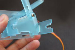
 1 x Servo 1 x Small servo screw 1 x Large servo screw 1 x Servo horn Thread your collar and attach, noting carefully the orientation. Insert the 12mm screws and half turn the nuts.")
28 2 x Nut 1 x 6mm Screw 1 x Collar 1 x RH Side piece 1 x Long lever (like you just used) 1 x Central lever RHS (look carefully at the picture!) 1 x Servo 1 x Small servo screw 1 x Large servo screw 1 x Servo horn Thread your collar and attach, noting carefully the orientation. Insert the 12mm screws and half turn the nuts. Attach the long lever to the outside of the RH Side piece with the 6mm screw. This is another part that needs to move. Remember nice and loose, these should move in plane so to speak. If it's stiff at first work it backwards and forwards a couple of times. Step 11: Attach to servo and set limits
29


30 Again take the plastic servo horn and attach it to the long middle section. Push this onto the servo and turn the servo gently all the way counter clockwise. Remove the lever and put it back on to match the first of the three images shown of the attached

31 lever here. Insert the small screw (not too tightly again!) and wind it clockwise so it matches the last image shown here. If you have your control board set up it's worth testing the movement of this part, if that securing screw binds the joint it's tricky to adjust later on. Step 12: Bringing the sides together and meeting the pig

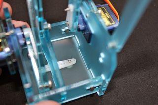
32 Now we're going to join the sides together with the central parts and meet one of my personal favourite pieces "the Pig". The Pig is shown in the second image here attached to a long lever, one of the iterations of this part looked a lot like a pig and the name has stuck with me. That is all! Parts needed: 2 x 12mm Screw 2 x Nut 1 x 6mm Screw 1 x Cradle base (squarish bit) 1 x LH Central lever 2 x Cradle ends 1 x "The Pig" 1 x Central section of central lever... 1 x Long servo horn

33 2 x Long servo screws 1 x Short servo screw Attach the Pig to the LH Central lever, as ever note the orientation of that screw! This time at least any mistakes will be apparent quickly. Again, you're going to get sick of this, but you want nice easy movement of that lever. Make sure it's in plane and spins around that screw easily. Step 13: Attach the servo horn to the base

34 Short step but best done now. Use the two long screws to attach this horn. Cut outs to the left like the picture. If you marry this up to one of the side pieces and think about how that horn will attach to the base it will help you get this part right. You can push fit it together and see before you attach for real too, so try that before charging ahead.


35 Step 14: Meeting old friends!

36

37 Show All Items Now we introduce all of the parts we've made over a very short time frame. This part is fiddly and really requires more hands than you have. Look at the pictures and read this through first. Take the assembled LHS (left hand side!) making sure the 12mm screws we attached earlier are pushed right through insert an end cradle piece so that the cutout is closest to the left hand side. Tighten that screw one or two turns, but not all the way. Now do the same with the other end part. With the screws loose try to insert the pig between the cut outs, it should just fit and hold, however depending on the cut and your luck it might not, loosen a screw if you need to. Nuts might fall, and you might well curse me right now. I deserve it. Please keep it together - literally and metaphorically. Once you've got that together and still with some slack in the screws you can slot in the cradle base. Now tighten but don't over tighten. Check all of the parts look like these pictures.

38 Step 15: Add the RHS
39

. That's the hardest part over with.")
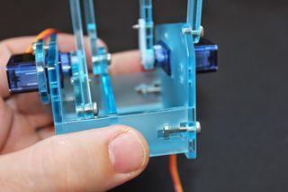
40 Now we're going to bring the RHS to the party. Using the two remaining nuts and two 12mm screws connect the central lever together loosely. Guide the base and LHS that you've just put together over the 12mm screws and nuts on the RHS and tighten everything up (do not over tighten!). That's the hardest part over with. It will look like you still have a lot of parts left but that's mainly the claw! Now for some easy wins... Step 16: Marry to the base!


41 This one is a nice easy step to follow that lot!
.")
42 Push your assembled cradle onto the base servo. Turn all the way clockwise and remove, put it back on as shown in the second image here and put the small screw in (not too tight!). Check that it turns anticlockwise and looks similar to the last picture here. Step 17: Left and right forearms
43


44 Show All Items The left is super simple. One part with two 6mm screws. Make it look like the second picture here! Again consider the movement of this part, tight enough to take out any wiggle not so tight as to bind the joint. The right forearm requires a spaces and you finally get to use two of those 10mm that you've been mistaking for the 12mms for the last hour! If you don't have three 10mm screws at this point have a look at the 12mm ones you've just used, one or more of them will look about 2mm shorter than the rest! The connection to the central lever on the right goes, central lever, forearm lever, triangle bit. At the back it's triangle bit, spacer, long lever (the one attached to the

45 RHS from earlier). Remember easy movement. If needed work the levers back and forth a few times. Now things are connected together this movement is going to give you an idea of how everything pulls together. Finally (for this step, don't get excited!) use the last long lever with a 6mm screw on the inside as shown on the last image here. I'm not going to have to say this again am I? Loose movement is the aim! Step 18: The Claw! (the claw...)
46


47 Show All Items This the beginning of the end you'll be pleased to hear! Now we'll use the rest of the bits. Except: 1 x Collar (Spare) 1 x Spacer (Spare) 2 x 8mm Screw 1 x 10mm Screw Find the shorter of the two rectangular parts. This is a specialised collar! Thread this like you've done the other three (or four if you broke one!).

48 Next use the thin parts shown in images five and six here. Note the orientation. These slide in the side and will act as mounts. I think this construction is very clever and it's the work of Jack Howard, co-creator of the #mearm. Now the larger rectangular part can be placed over the bottom of the composite part you've just made. Check the orientation a final time and reach for four of your remaining 8mm screws and don't over tighten them! But do tighten them. Make sure none protrudes from the base of the part you've just made. Step 19: Jaws
49


50 Show All Items Take a 6mm screw and attach the toothed jaw with two holes to the left hand side of the claw. For best results make sure these two parts are as flush as possible as you self tap the screw. If you find your gripper is moving off plane then remove the part, hold it flush again and recut the thread. Line up the other jaw to mesh correctly and attach that flush with another 6mm screw. Test the movement of the jaws now. If it's not free and easy it could be the joints as discussed earlier, it could be they're off plane (remove and recut thread) or it could

51 be that the 8mm screws we used for the clamp are just touching the back of the gears, loosen them off a touch. Next we'll make the linkage to connect the servo and jaws together. Attach your remaining horn to the short servo connecting lever. Then connect this to the little tiny linking part. That should have been your last 6mm screw. Now with the last 12mm you have push it through the tiny linking part, add two spacers and possibly the washers we include and attach to the spare hole in the left hand jaw. I tend to leave this unconnected to the servo until I have microcontroller control and can decide where the close position is. Step 20: The final step!


52 All that remains is to attach the claw to the rest of the robot! Use two 8mm screws into the pivot of the claw and the final 10mm with a spacer to secure the wrist. The 8mm screws normally come into contact with the top and bottom of the clamp before
53 finding the hole in the spacer parts, you can make this easier by loosening the screws to on the servo clam slightly. Now it's time to connect it to your favourite controller! Links are on the front page of the instructable to the available code and connection guides are with each. Where you can use 6V for the servos, that extra volt is worth quite a bit of torque. Once connected you might find you need to make fine adjustments to the build, most likely you've over tightened parts and will need to give them a little slack. I hope you've enjoyed this Open Source build! I look forward to seeing your #mearms in action!
Installation Instructions for FC2 & FC15 Forward Controls for the Super Magna
 Installation Instructions for FC2 & FC15 Forward Controls for the Super Magna It is highly recommended that you use a thread lock compound such as Loctite brand on all threads to keep them from vibrating
The Useless Machine. DIY Soldering Edition. Instruction Guide v0004
 The Useless Machine DIY Soldering Edition Instruction Guide v0004 TM For the best outcome, follow each step in order. We recommend reading this guide entirely before you get started. Tools required: Soldering
Technicians of Terror. This is the air valve we make to use with our air
 These are pictures of our scissor prop. Technicians of Terror http://www.halloweenfear.com/scissorprop.html props. This is the air valve we make to use with our air This pictures the duel door closer cylinders
Ohbot. Eyes turn. servo. Eyelids open. servo. Head tilt. servo Eyes tilt. servo. Mouth open servo. Head turn servo
 Making Instructions Ohbot Ohbot has six servo motors. The servos allow each part of the face to be positioned precisely. Eyelids open servo Eyes tilt servo Eyes turn servo Head tilt servo Mouth open servo
Hardware and Components:
 Hardware and Components: (A) 5/16 x 2 Hex Bolt (B) 5/16 x 2-1/4 Hex Bolt (C) 5/16 x 2-1/2 Hex Bolt (D) 4X 5/16 x 3/4 Hex Bolt (E) 4X 5/16 x 1-1/4 Hex Bolt (F) 11X 5/16 Flat Washer (G) 12X 5/16 Nylock Nut
Lumber Smith. Assembly Manual. If you are having problems assembling the saw and need assistance, please contact us at:
 Lumber Smith Assembly Manual If you are having problems assembling the saw and need assistance, please contact us at: 804-577-7398 info@lumbersmith.com 1 Step 1 Safety Carefully read the Owners Manual.
Hardware and Components:
 Hardware and Components: (A) 4X 5/16 x 1 Carriage Bolt (B) 2X 5/16 x 2-1/4 Carriage Bolt (C) 2X 5/16 x 3-1/4 Hex Bolt (D) 2X 5/16 x 3/4 Hex Bolt (E) 2X 5/16 x 1-1/4 Hex Bolt (F) 5/16 x 2-1/4 Hex Bolt (G)
001-Component-build. Build the following Contraptor components before assembly:
 001-Component-build Build the following Contraptor components before assembly: http://www.contraptor.org/make-linear-rail-v2#assembly http://www.contraptor.org/make-linear-bearings-v2#assembly http://www.contraptor.org/make-sliding-elements#assembly
ESRA III. Expressive System for Robotic Animation
 ESRA III Expressive System for Robotic Animation 1 ESRA III Kit Contents 1 Hitec Servos 8 Upper Eye Support 2 Dagu (New as of 7/12) 9 Lower Eye Support 3 Eye Balls 10 Main Support 4 Flat Servo Plate 11
tinycylon Assembly Instructions Contents Written by Dale Wheat Version August 2016 Visit dalewheat.com for the latest update!
 tinycylon Assembly Instructions Written by Dale Wheat Version 2.1 10 August 2016 Visit dalewheat.com for the latest update! Contents Assembly Instructions...1 Contents...1 Introduction...2 Quick Start
Written By: Joseph Schlesinger
 Building an ArcBotics Hexy Written By: Joseph Schlesinger PARTS: 1 ArcBotics Hexy Kit (1) SUMMARY We're going to build a hexapod! Make Projects www.makeprojects.com Page 1 of 20 Step 1 Building an ArcBotics
Cut-True 16M Manual Paper Cutter
 Cut-True 16M Manual Paper Cutter 2/2013 OPERATOR MANUAL FIRST EDITION TABLE OF CONTENTS TOPIC PAGE Specifications 1 Safety Guidelines 1 Assembly 2 Overview 3 Description of Equipment Parts 3-4 Operation
Installing CNC Stepper Motor Mounts On A Sherline Mill
 Installing CNC Stepper Motor Mounts On A Sherline Mill P/N 6700 (6710 Metric) 5000/5100/5400/5410 Mills P/N 6705 (6715 Metric) 2000/2010 Mills USING THE TEMPLATE BLOCKS TO LOCATE NEW MOUNTING HOLES FOR
DeRosa DRM-516 (5-PIECE 16 ) Drum Kit ASSEMBLY INSTRUCTIONS
 Drum Kit ASSEMBLY INSTRUCTIONS") DeRosa DRM-516 (5-PIECE 16 ) Drum Kit ASSEMBLY INSTRUCTIONS Along with reading this guide, we also recommend that you watch the DeRosa 516 Drum Kit Assembly video on the Austin Bazaar Product FAQ page
DeRosa DRM-516 (5-PIECE 16 ) Drum Kit ASSEMBLY INSTRUCTIONS Along with reading this guide, we also recommend that you watch the DeRosa 516 Drum Kit Assembly video on the Austin Bazaar Product FAQ page
Assembling the BoXZY Enclosure
 Assembling the BoXZY Enclosure Your newly purchased enclosure requires a small amount of assembly. This guide will walk you through how to assemble the enclosure. Written By: Nicki 2018 boxzy.dozuki.com/
INSTALLING YOUR NEW SPRING LIFT ARM KIT
 INSTALLING YOUR NEW SPRING LIFT ARM KIT 1. Measure the distance that the roof is to be raised. [If your lift system is completely non-functional, you will need to calculate or estimate this distance as
The build should take around 2 to 3 hours. However, by leaving yourself more time you can go at a relaxed pace and be sure not to miss anything.
 Before We Start Before we jump into building your Picade, make sure you have everything to hand. I know you're eager to jump right into the construction, but we need to get set up properly first! 1. Prepare
Harmony Remote Repair
 Harmony Remote Repair harmonyremoterepair.com How to install your new Harmony One Front Cover/Touch Screen Important! Before you begin working on your Harmony One, you must discharge any static electricity
Joiner Kit For Models N388, C450, E402B, E411T, E415H, E440T, E442B, E521T and E522B
 Joiner Kit For Models N388, C450, E402B, E411T, E415H, E440T, E442B, E521T and E522B KIT COMPONENTS Part Illustration Description Rear Bracket Front Lower Bracket Front Upper Bracket KIT APPLICATION This
CV1B Sliding Table Installation and Setup Guide
 CV1B Sliding Table Installation and Setup Guide Tech Mark, Inc 7901 Industry Drive North Little Rock, AR 72117 tel (501) 945-9393 fax (501) 945-0312 www.tech-mark.com email: info@tech-mark.com The CV1B
FW450/550 Multifunction Landing Strut Set
 FW450/550 Multifunction Landing Strut Set 1 Copyright 2013 PhotoShip One LLC - www.photoshipone.com Assemble the clamp pieces with M3x8 screws The Multifunction Landing strut set is intended to provide
Regardless of how you got here, you have keys that don't match, and you'd like to have a one-key system. Well, today is your lucky day!
 Vollkswagen Cabriiollet DIY Guiide Removiing Door Handlles & Repaiiriing Door Locks This how-to was originally posted on VWvortex.com by scirocco*joe : http://forums.vwvortex.com/zerothread?id=3496179.
O W N E R ' S M A N U A L
 TABLE TENNIS TABLE MODEL NOS. T861 T861B O W N E R ' S M A N U A L 1. Read this manual carefully before starting assembly. Read each step completely before beginning each step.. Some smaller parts may
Tool Wagon Assembly Instructions
 Tool Wagon Assembly Instructions Adhesives Wood to wood joints are best done with a PVA wood glue but a good quality, slow acting (beware of instant grab ) cyanoacrylate super glue can be used if preferred.
AndyMark DART 12.
 AndyMark DART 12 Part Number Description QTY These Parts Are Pre-Assembled by AndyMark am-0031 Bearing, 3/16"ID (R3) 1 am-0209 Bearing, 3/8"ID 1614ZZ 2 am-1028 Screw, #10-32x3/8 Pan Head Philips 8 am-1121
OpenROV. Guide 3 - Electronics. We will now move to the assembly of the electronics that will control the ROV. Written By: OpenROV
 OpenROV Guide 3 - Electronics We will now move to the assembly of the electronics that will control the ROV. Written By: OpenROV 2017 openrov.dozuki.com Page 1 of 33 INTRODUCTION We will introduce soldering
ABM International, Inc.
 ABM International, Inc. Lightning Stitch required 1 1.0: Parts List head and motor assembly (Qty. 1) Reel stand (Qty. 1) Needle bar frame clamp (Qty. 1) Motor drive (Qty. 1) 2 Cable harness with bracket
CNC Using the FlexiCam CNC and HMI Software. Guldbergsgade 29N, P0 E: T:
 CNC Using the FlexiCam CNC and HMI Software Guldbergsgade 29N, P0 E: makerlab@kea.dk T: +46 46 03 90 This grey box is the NC controller. Let s start by turning the red switch to the ON position, then press
Midwest RDH Handpiece Repair Procedure
 Midwest RDH Handpiece Repair Procedure The Midwest RDH handpiece is fairly common and is used by hygienists to clean teeth. The most common problems for this handpiece include a bad prophy head or a dirty
Metroboard Pulley Replacement Procedure
 Metroboard Pulley Replacement Procedure 1) Remove the two transmission cover screws (1/8 allen driver). Then remove the transmission cover. Note there is a split lock washer and flat washer as well, so
Depending on the size you ordered you will have either 5 Foot sections which will build the 10 Foot frame or 6 Foot sections which will build the 12
 XL Quilting Frame 1 Depending on the size you ordered you will have either 5 Foot sections which will build the 10 Foot frame or 6 Foot sections which will build the 12 Foot frame Printed 2 June 2014 Updated
TELESCOPIC GATE MANUFACTURING AND INSTALLATION MANUAL.
 TELESCOPIC GATE MANUFACTURING AND INSTALLATION MANUAL. Telescopic gates have been manufactured for many years essentially in the same way they are largely today. In recent years hardware suppliers have
Robodyssey ESRA III. Expressive System for Robotic Animation
 Robodyssey ESRA III Expressive System for Robotic Animation Assembly and Operation Instructions Version 1.0 Robodyssey Systems, LLC. Phone/Fax: 609-585-8535 20 Quimby Avenue Web: www.robodyssey.com Trenton,
Note - the nose ribs and are thinner than the main ribs. These nose ribs will use a thinner rib cap than the ribs. This is per design.
 Stabilizer rev 1.2 The SE5a stabilizer is the heartbeat of the tail and is recreated like the full scale version. All tail pieces depend on the stabilizer. It uses the steel fittings, pulleys, inspection
The Mind Project s Iris 1 Robotic Arm. Packing List Assembly instructions
 The Mind Project s Iris 1 Robotic Arm Packing List Assembly instructions Packing list Below you will find pictures and descriptions of each part. It may be helpful to take each piece out of the bag and
The Mind Project s Iris 1 Robotic Arm. Assembly instructions Step 1
 The Mind Project s Iris 1 Robotic Arm Assembly instructions Step 1 Packing list Below you will find pictures and descriptions of each part. It may be helpful to take each piece out of the bag and place
SuperTrack Parts List
 SuperTrack Parts List [indicates number for 6 lane tracks] SuperTrack Installation Instructions www.supertimer.com 1-800-654-2088 1 Track Instruction Manual (this booklet) 2 Start sections [3] Start Gate
https://www.wallbedsbywilding.com/wallbed-installation-studio-series/
 For Wallbed models: KING SIZE INSTRUCTION BOOKLET #C1 Watch step by step installation instructions at: https://www.wallbedsbywilding.com/wallbed-installation-studio-series/ WARNING! ALL MURPHY/WALLBED
Installation instructions for FC14S Forward Controls for Shadow ACE and Aero 1100
 Installation instructions for FC14S Forward Controls for Shadow ACE and Aero 1100 It is highly recommended that you use a thread lock compound such as Loctite brand on all threads to keep them from vibrating
Castle Frame Assembly Table AT-8. Diagnostics Manual. Castle, Inc. Petaluma, CA
 Castle Frame Assembly Table AT-8 Diagnostics Manual Castle, Inc. Petaluma, CA 800-282-8338 Solutions Index Adjusting the Tabletop.. 8.01 Adjusting the Fence... 8.02 Aligning the Arm... 8.10 Adjusting Bracket..
CHAPTER 8. Through Dovetail Procedures
 CHAPTER Through Dovetail Procedures 52 Chapter D4 User Guide THROUGH DOVETAIL PROCEDURES Chapter Foreword In these instructions for using the Leigh Dovetail Jig, we have recommended using certain cutters
F-F-Fiddle Assembly Instructions
 F-F-Fiddle Assembly Instructions Bout Bridge Neck Machine Heads/Tuners Truss Rod Strings An open-source FFF 3d-printable electric violin. 1. Assemble materials 5 3 8 1 9,10, 11 7 4 2 6 PARTS 1. Bout part
Installing CNC Stepper Motor Mounts On A Sherline Lathe
 Installing CNC Stepper Motor Mounts On A Sherline Lathe P/N 6720 (6725 Metric) 4000/4100/4500/4600 Lathes P/N 6730 (6735 Metric) 4400/4410 Lathe USING THE TEMPLATE BLOCKS TO LOCATE NEW MOUNTING HOLES FOR
 INSTRUCTION BOOKLET #C0 Watch step by step installation instructions at: https://www.wallbedsbywilding.com/wallbed-installation-studio-series/ WARNING! ALL MURPHY/WALLBED SYSTEMS CONTAIN STORED ENERGY.
Replacing the Reciprocator on the SWF Compact Series Machine (601C and 1201C)
") Follow the instructions below to replace the reciprocator in the SWF Compact series machines. The tools required can be found in the tool kit that came with the machine. Preparation 1. First, place the
Follow the instructions below to replace the reciprocator in the SWF Compact series machines. The tools required can be found in the tool kit that came with the machine. Preparation 1. First, place the
Sew a Yoga Mat Bag with Ashley Nickels
 Sew a Yoga Mat Bag with Ashley Nickels Chapter 1 - Introduction Overview Hi, I'm Ashley Nickels. I'm a sewer and a quilter. And one of my favorite things to do is design bags. And I designed this yoga
ORTOP Modular Robot v3.0 Arm Assembly
 Base Plate Assembly Parts Needed: Arm Assembly BAG 1 2 Socket Head Cap Screw, 1-1/4" 2 Socket Head Cap Screw, 1/2" 2 Button Head Cap Screw, 3/8" 6 Nuts 1 Gear Hub Spacer 1 Flat Building Plate 1 Single
Low/High Tunnel Greenhouse Plans
 Low/High Tunnel Greenhouse Plans Tools Needed (See the complete list of Greenhouse Tools) Hacksaw or Reciprocating Saw Socket Wrench, Adjustable Wrench or Nut Drivers Electric Drill with Drill Bits Sledge
Build your own. Stages 7-10: See Robi s head move for the first time
 Build your own Pack 03 Stages 7-10: See Robi s head move for the first time Build your own All rights reserved 2015 Published in the UK by De Agostini UK Ltd, Battersea Studios 2, 82 Silverthorne Road,
The Useless Machine. Parts Only - Build Guide v0001
 TM The Useless Machine Parts Only - Build Guide v0001 For the best outcome, follow each step in order. We recommend reading this guide entirely before you get started. Tools required: One phillips screwdriver,
Electric Skein Winder
 Electric Skein Winder Assembly and Use Package Contents 1 - Triangular Body (w/ motor) 1 - Cross Arm 1 - Left Foot (w/ yarn guide) 1 - Right Foot 1 - Adjustable Finger (w/ yarn clip) 3 - Adjustable Fingers
 www.wildmanconstruction.com Changing your toilet is an easy project that should take half a day or less. The most common toilet has a separate tank that mounts on top of the bowl. These instructions apply
COMMON WRENCHES INTRODUCTION
 COMMON WRENCHES INTRODUCTION A wrench is a hand tool used to provide grip and mechanical advantage in applying torque to turn objects usually nuts and bolts. Wrenches allow us to use less force to rotate
Plug-n-Show Stake Down Pixel Tree Kit 16 strips of 25 pixels Assembly Instructions
 www.lightorama.com Plug-n-Show Stake Down Pixel Tree Kit 16 strips of 25 pixels Assembly Instructions Read all instructions before you start Kit assembly! STEP 1. Check that all parts are included Parts
Written By: Brook Drumm
 Simple 1401 Assembly For kits produced between 1/15/14-6/1/14. This guide is for kits with the Fan Shroud. Instructions for metal and wood extruder (and bed) included below. Written By: Brook Drumm TOOLS:
HQ Pole Upgrade Kit for HQ Adjustable Table and HQ QuilTable Assembly Instructions 1
 HQ Pole Upgrade Kit for HQ Adjustable Table and HQ QuilTable Assembly Instructions QF09775 The pole upgrade kit can be used with or without the QF09700 HQ Precison-Glide track upgrade kit. What s Included
Practicing Basic Machine Operation Sample #1
 Practicing Basic Machine Operation Sample #1 Listed below are various tasks required in basic sewing machine operation. Demonstrate your ability to perform each task by creating a sample. The samples that
 For Wallbed models: KING SIZE INSTRUCTION BOOKLET #C1 Watch step by step installation instructions at: https://www.wallbedsbywilding.com/wallbed-installation-studio-series/ WARNING! ALL MURPHY/WALLBED
Sentinel Series Cigar Humidor End Tables
 Sentinel Series Cigar Humidor End Tables Assembly Instructions Models: Sentinel 500, 1000 and 1500 Style: Traditional SENTINEL ASSEMBLY INSTRUCTIONS Congratulations! You have purchased a superior cigar
40 & 50 Foot PS-1 Box Car Assembly Instructions
 40 & 50 Foot PS-1 Box Car Instructions Push the #2100 coupler/stirrup assembly onto the ends of the metal floor. Slide them into the slots and slightly lift the ends (wings), then press firmly on the front
HQ Precision-Glide Track Upgrade 2 Extension Kit for HQ Studio Frame Part# QF09750
 HQ Precision-Glide Track Upgrade 2 Extension Kit for HQ Studio Frame Part# QF09750 Important Note: Upgrading the track system on the HQ Studio Frame requires the use of this 2 Extension Kit (Part #QF09750),
Kossel Rev B Build Guide V1.0
 Kossel Rev B Build Guide V1.0 1 Table of Contents: Step 1: BASE ASSEMBLY Gathering parts: Building the Corners and Base: Step 2: UPPER ASSEMBLY Building Upper: Step 3: VERTICAL RAIL INSTALLATION Building
 INSTRUCTION BOOKLET #C10 Watch step by step installation instructions at: https://www.wallbedsbywilding.com/wallbed-installation-studio-series/ WARNING! ALL MURPHY/WALLBED SYSTEMS CONTAIN STORED ENERGY.
1.75mm Direct Titan Assembly
 1.75mm Direct Titan Assembly Learn how to assemble your Titan for use with 1.75mm filament in a direct configuration. Written By: Gabe S. 2018 e3d-online.dozuki.com/ Page 1 of 20 TOOLS: Hex Wrench, 1.5mm
WARNING: Prior to installation, turn the power off to the vending machine and unplug it from its power source. Also, make sure to level the machine.
 Installation of Gum and Mint Tray for National 147, 157, 167 Important Note: Please read all instructions thoroughly before continuing with installation of kit. If you are having problems installing the
Adjusting Backlash on Sherline handwheels
 WEAR YOUR SAFETY GLASSES FORESIGHT IS BETTER THAN NO SIGHT READ INSTRUCTIONS BEFORE OPERATING Adjusting Backlash on Sherline handwheels What Is Backlash? Backlash is the amount the handwheel can turn before
StenBOT Robot Kit. Stensat Group LLC, Copyright 2018
 StenBOT Robot Kit 1 Stensat Group LLC, Copyright 2018 Legal Stuff Stensat Group LLC assumes no responsibility and/or liability for the use of the kit and documentation. There is a 90 day warranty for the
FABA. Installation Instructions. Conductor Bar System. Publication #FABA-03 3/1/04 Part Number: Copyright 2004 Electromotive Systems
 FABA Conductor Bar System Installation Instructions Publication #FABA-03 3/1/04 Part Number: 005-1062 Copyright 2004 Electromotive Systems 1S 100 Z Installation Instructions Contents: Basic Diagram - -
======================================================================================== ( DR / DR) JK WRANGLER MOD RACK
 JK WRANGLER MOD RACK") (10984 4DR / 10982 2DR) JK WRANGLER MOD RACK INSTALLATION SHEET Important Notes: Some brands of windshield light brackets and snorkels may not be compatible with the 10984 MOD Rack System. Body lifts are
(10984 4DR / 10982 2DR) JK WRANGLER MOD RACK INSTALLATION SHEET Important Notes: Some brands of windshield light brackets and snorkels may not be compatible with the 10984 MOD Rack System. Body lifts are
Titan Aero Assembly. Titan Aero Assembly. Learn to assemble your Titan Aero. Written By: Gabe S e3d-online.dozuki.
 Titan Aero Assembly Learn to assemble your Titan Aero Written By: Gabe S. 2018 e3d-online.dozuki.com/ Page 1 of 26 INTRODUCTION The Titan Aero is a very similar build to a Titan and a V6 put together (which
A3 Jetta TDI Chip Upgrade
 A3 Jetta TDI Chip Upgrade View the online version at http://vw.ogdenlabs.com/kerma.htm I'm writing this article to show how to go about upgrading an A3 Jetta TDI. Please be aware that this is for information
Basic Bearmaking Instructions
 Laying out the Pattern Basic Bearmaking Instructions We recommend that you read the instructions right through before commencing. This will help you to understand the steps you need to take. Copying your
GoPro Hero Camera Mount. Assembly Manual
 GoPro Hero Camera Mount Assembly Manual Introduction Thank you for purchasing the GoPro Hero Camera Mount for Mikrokopter Quad, Hexa and Okto. The Camera Mount is provided as a kit and requires assembly.
ABM International, Inc. Navigator Assembly Manual
 ABM International, Inc. 1 1.0: Parts List Tablet (Qty. 1) Tablet mount (Qty. 1) NOTE: Mount may appear and operate different then image below Control Box (Qty. 1) Motor Power Supply (Qty. 1) 2 X-axis motor
AM8 Printer A metal frame for your Anet A8 By Pheneeny v1.0 April 20, 2017
 AM8 Printer A metal frame for your Anet A8 By Pheneeny v1.0 April 20, 2017 Please read this entire document before printing parts or building this frame Disclaimer: This guide is for informational purposes
Sunrise Deck Assembly Instructions for Kingston Left
 Sunrise Deck Assembly Instructions for Kingston Left It s easiest to build the deck frame first like it will be lying on its back and then after all 4 legs and horizontals are in place, tip the deck toward
Step 1: The larger tower box contains the tower machine, a set of Silver 100 Lid Keys, and a set of Black 002 Coin Box Keys
 2 3 Step 1: Each tower is shipped as two boxes the large tower box and the smaller stand box. Open each of the boxes and inventory each of the parts before starting assembly to ensure all parts have arrived.
BABY WOLF LOOM. Assembly Instructions for Knocked-Down Looms
 BABY WOLF LOOM Assembly Instructions for Knocked-Down Looms BEFORE YOU BEGIN Please read through the directions before beginning to assemble your loom. Unpack the loom parts carefully. Do not throw away
Modular Locomotive System Instruction Manual for HBK22 Fowler Body Kit
 Modular Locomotive System Instruction Manual for HBK22 Fowler Body Kit Roundhouse Engineering Co. Ltd. Units 6-10 Churchill Business Park. Churchill Road, Wheatley. Doncaster. DN1 2TF. England. Tel. 01302
Assembly. Insert stem and then fix/lock using the grub screw as in picture.
 Assembly Parts list: (Boxed set) Body inc hinge plate x1 M33 x 3.5 16 tpi + depth stop collar x1 1 stem + collar x1 HSS cutter x1 Bristol handle x1 Twist handle x1 4mm Allen key x1 3mm Allen key x 1 Instruction
Chain Drive Vise. Installation Instructions. (revised 05/04/2016)
") Chain Drive Vise Installation Instructions (revised 05/04/2016) Lie-Nielsen Chain Drive Vise Instructions Table of Contents page About Your Chain Drive Vise 3 Parts List 4 Exploded Parts Diagram 5 step
Chain Drive Vise Installation Instructions (revised 05/04/2016) Lie-Nielsen Chain Drive Vise Instructions Table of Contents page About Your Chain Drive Vise 3 Parts List 4 Exploded Parts Diagram 5 step
Induku Wooden Models. Orrery. Assembly Instructions
 Induku Wooden Models Orrery Assembly Instructions 2 Thank you for shopping at Induku Design. I hope you enjoy building the Orrery as much as I did making it! For any questions or comments, please contact
Making a Cement Upper Molding Surface for Compression Molding of Shape&Roll Prosthetic Foot Cores
 Making a Cement Upper Molding Surface for Compression Molding of Shape&Roll Prosthetic Foot Cores Andrew Hansen, PhD Steven Steer, MS Kerice Tucker Elizabeth Klodd Craig Heckathorne, MS Northwestern University
Race Splitter Upgrade Kit Installation Instructions
 Race Splitter Upgrade Kit Installation Instructions Eric Hazen Rev. 1 Overview: Detailed instructions on installing the FT86 Speed Factory Race Splitter Upgrade Kit on a BRZ; FR-S grills are different
EZ-Lock Assembly Manual
 ABM International, Inc. EZ-Lock Assembly Manual 1 ABM International, Inc. Series: 1018/1022/1026 V1.0 EZ-Lock Parts List - Structural frame profiles Slotted beam: (Qty. 2) 15.75 Commercial Parts - Liner
MACHINE QUILTING FRAME
 MACHINE QUILTING FRAME YOU WILL NEED TO PURCHASE: 5 pieces of 1-1/4 thin wall metal conduit (EMT) cut to your preferred length for the rollers. (Maximum 120 ) DETERMINING YOUR ROLLER LENGTH: Determine
WorkBee CNC. Mechanical Assembly Instructions - Screw Driven
 WorkBee CNC Mechanical Assembly Instructions - Screw Driven Table of Contents 1.0 Getting Started 2 1.1 About The Kit 3 1.2 Check Product Contents 3 1.3 Tools Required 3 1.4 Notes on Assembly 3 2.0 Assembly
Basic steps to time the Gammill quilting machine s rotary sewing hook
 Basic steps to time the Gammill quilting machine s rotary sewing hook 1.) Turn the machine off and unplug it. 2.) With the needle bar in the raised position, remove the bobbin and bobbin case. 3.) Remove
Kromski Minstrel Assembly Instructions
 Kromski Minstrel Assembly Instructions Important Notice If you have any difficulty in understanding these instructions, assembling the wheel, or having it operate to its fullest potential, WE WANT YOU
HFp. User s Guide. Vertical. entenna. 7 MHz 30 MHz Amateur Radio Antenna Plus 6-Meters
 User s Guide HFp Vertical 7 MHz 30 MHz Amateur Radio Antenna Plus 6-Meters The Ventenna Co. LLC P.O. Box 2998, Citrus Heights, CA, 956 www.ventenna.com entenna Table of Contents The HFp Antenna -------------------------------------------------------------------
1 Toe-Up Socks Tutorial
 1 of 23 One Toe-Up Socks on Two Circular Needles Tutorial A sock knitting tutorial by Kristin - www.cometosilver.com/socks This is an intermediate level sock knitting tutorial. It is best suited for the
PORTA-DOCK, INC. AP17 APD DS 4 X 16 T12 AW17 CPD DS 4 X 16 T12
 Page 1 of 7 PORTA-DOCK, INC. AP17 APD DS 4 X 16 T12 AW17 CPD DS 4 X 16 T12 *For Beige Decking Add the Letter B to Model* Thank you for purchasing out product! *Please read these instructions and follow
Build your own. Pack. Stages 19-22: Continue building Robi s left arm
 Build your own Pack 06 Stages 19-22: Continue building Robi s left arm Build your own All rights reserved 2015 Published in the UK by De Agostini UK Ltd, Battersea Studios 2, 82 Silverthorne Road, London
Thor Audi A4/S4 Skid Plate Installation Instructions
 Thor Audi A4/S4 Skid Plate Installation Instructions Parts List: 1 Aluminum Skid Plate 2 Aluminum Side Wings 10 10mm Flat Washers 3 8mm Flat Washers 3 8mm Speed Clips 2 10x40mm Bolts 3 8x35mm Bolts 2 Rivet-nuts
Side Mount INSTRUCTION BOOKLET #C122 BED STYLE: PARK CITY
 Side Mount BED STYLE: PARK CITY INSTRUCTION BOOKLET #C1 WARNING! ALL MURPHY/WALLBED SYSTEMS CONTAIN STORED ENERGY. FAILURE TO USE AND FOLLOW THESE INSTRUCTIONS DURING THE INSTALLATION PROCESS COULD RESULT
Quill Stop V2 Installation Guide 11/16/2014
 Thank you for purchasing the Quill Stop for the Sieg X3 (Grizzly G0463) and SX3 (Grizzly G0619) mills. Your feedback is always appreciated. Please email questions and comments to gregpriest@cox.net. What
INSTRUCTION BOOKLET #C20
 INSTRUCTION BOOKLET #C0 WARNING! ALL MURPHY/WALLBED SYSTEMS CONTAIN STORED ENERGY. FAILURE TO USE AND FOLLOW THESE INSTRUCTIONS DURING THE INSTALLATION PROCESS COULD RESULT IN SEVERE PERSONAL INJURY TO
GROUND BALANCE & PINPOINT BUTTON MODIFICATION By Sven Stau October 2008
 TESORO CIBOLA GROUND BALANCE & PINPOINT BUTTON MODIFICATION By Sven Stau October 2008 Get some added performance by replacing the internal factory fixed GB with an external user friendly, fully adjustable
WOLF LOOM DOUBLE BACK BEAM
 WOLF LOOM DOUBLE BACK BEAM Assembly Instructions Find out more at schachtspindle.com Schacht Spindle Company 6101 Ben Place Boulder, CO 80301 p. 303.442.3212 f. 303.447.9273 2017 Schacht Spindle Company,
SAVVY OFF ROAD GAS TANK SKID INSTALLATION INSTRUCTIONS
 It is best to work with a fuel tank that has the least amount of fuel in it as possible. Thank you for purchasing the best skid on the market. Please follow these instructions and your installation should