DIGITAL EARTH FAULT RELAY
|
|
|
- Miles Allen
- 5 years ago
- Views:
Transcription

1 DIGITAL
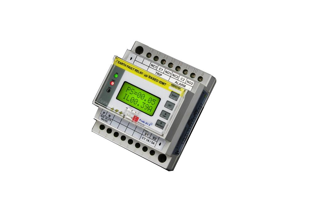
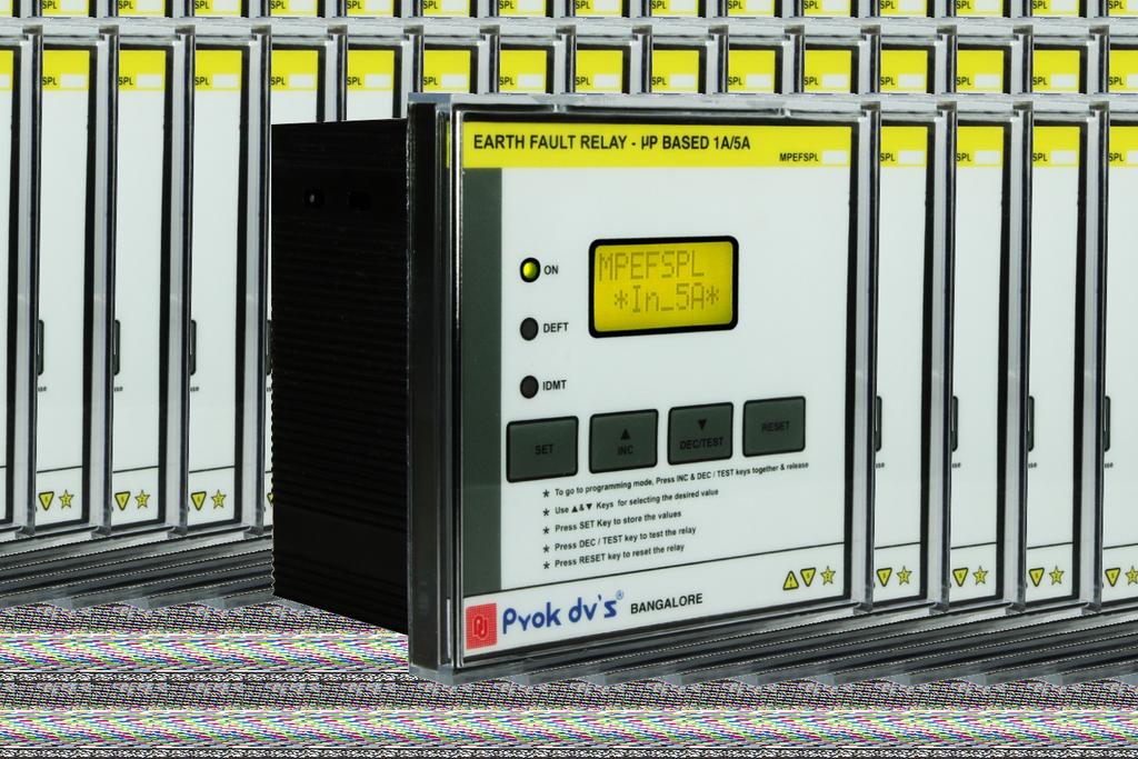
2 IDMT / DEFINITE TIME / INSTANTANEOUS Features ŸCompact ŸIDMT (4 IEC curves), Definite Time & Instantaneous ŸWide setting ranges ŸFully digital acquisition & processing of data ŸWide operating voltages ŸLCD display of operated current & fault current ŸRugged and Tropicalized design Applications ŸEarth Fault Protection for Generators / Alternators ŸEarth Fault Protection for Transformers & Feeders Specifications SPECIFICATIONS Auxiliary Voltage Frequency Neutral or Summation CT rated Current-In Burden on CT Sensitivity Settings Plug Setting Range(PS) Definite Time Settings in Sec IDMT / DEFINITE TIME / INSTANTANEOUS (EFR) V AC/DC or V AC/DC 50Hz 1A / 5A ( Field Selectable ) <0.2VA PS Range : (5%-80%) of In. in steps of 5% Sec. (200 Steps) in steps of 0.10 Sec. IDMT Curves 4 IDMT Curves : Normal Inverse (NI) 1.3 Sec 3.0 Sec Long Time Delay (LTD) Time Setting Multiplier (TMS) ( ) in steps of 0.05 High Set Enable/Disable Option High Set Time for High Set Operation CBCT/ZCT size for EFR Contact Capacity (A) Contact type Available (0.5-16) In. in steps of 0.1 ( ) Sec. in steps of 0.1 Sec Circular: 40mm,65mm,100mm,150mm,200mm,250mm&300mm with Secondary 1A only 8A@250V AC 8A@30V DC NC-C-NO Two change over
3 IDMT / DEFINITE TIME / INSTANTANEOUS Operating Temperature ( C) -5 C C Standard IEC Relay Setting Mode Setting through push button Selection of the relay rating- 5A or 1A (In) PS - selection Curve Selection TMS - selection for IDMT Time - for DEFT Relay TEST RESET Display/Indication Back-Lit LCD display Two line 8 characters Trip value of the current w.r.t. Secondary of CT Set PS value. Red LED-DEFT/IDMT trip Relay Test Facility Available through push button Mounting Type Flush Din/Surface Dimensions in mm Flush : 96 x 96 x 70 Din : 80 x 95 x 75 (W x H x D) Panel cut out in mm (Flush type) 90 x mm Description PROK DEVICES PVT LTD an ISO company introduces DIGITAL MICROPROCESSOR / MICROCONTROLLER BASED IDMT / DEFINITE TIME / INSTANTANEOUS (EFR).It is a current sensing device which is tropicalised professionally designed and tested for protection of Generators, Transformers and Feeders. Prok dv's make IDMT / DEFINITE TIME / INSTANTANEOUS (EFR) can be employed with various earth fault protective schemes, which are explained in brief with figures. The magnitude of the earth fault current depends on the fault impedance and invariably the fault impedance for earth fault is higher than that for phase faults, hence the earth fault current is low compared to the phase fault currents. The fault impedance depends on the system parameter and also on type of earthing. The neutral may be solidly grounded, grounded through resistance or reactance. The unit has LCD for displaying the fault current (at the time of tripping) and setting values (curves, plug setting & TMS). The LEDs are provided for indicating power ON status and to indicate IDMT or DEFINITE TIME or INSTANTANEOUS mode operation. Key pads are provided for easy setting/changing of the parameters.the design is tropicalised and rugged. The IDMT / DEFINITE TIME / INSTANTANEOUS (EFR) measure the current using sampling technique. The analog current signal obtained from the protection CT is stepped down using interposing CT. Current signal is then applied to signal conditioning circuit using the buffer. Signal is then level shifted by adding DC level. This uni-polar signal is applied to ADC of the processor.
 the algorithm evaluates the trip time.")
4 IDMT / DEFINITE TIME / INSTANTANEOUS The ADC samples the signal in every cycle. The samples are used to determine the magnitude of the signal. The calculated amplitude value is checked with the set value at every sample instant. When the evaluated value is greater than the set (Current) the algorithm evaluates the trip time. If the operating condition is met the trip initiating signal is issued after the elapse of calculated tripping time. Figure A Shows how an Earth Fault Relay (EFR) can be energized by a residual current, in this method the secondary 3 CT currents, by summation technique Ir, Iy & Ib of three different phases are connected in parallel. The vectorial sum of three current ie (Ir+ Iy + Ib ) is zero under normal condition. During the occurrence of earth fault the residual current is non-zero and when it exceeds the pick-up value (Site Selected), the Earth Fault Relay(EFR) trips. Theoretically during balanced load conditions the Earth Fault Relay (EFR) carries no current hence its current, setting may be any value greater than zero, but in practice such ideal system do not exist. Using the summation techniques it is possible to detect Earth Fault current in the Electrical power system, the choice of summation can be made according to site condition, Economic condition and the Electrical protection scheme. Figure B Shows schemes for IDMT / DEFINITE TIME / INSTANTANEOUS (EFR) used for protection of Transformer and Generator. On occurrence of earth fault, zero sequence current flows through the neutral, in-turn actuating the earth fault relay (EFR). Figure C shows a scheme with IDMT / DEFINITE TIME / INSTANTANEOUS (EFR) which utilized a special type of C.T., called core balance current transformer (CBCT/ZCT) which is toroidal in nature, under normal condition of 3 phase to phase faults the current in the toroidal secondary is zero. During earth fault the reflected zero sequence unbalance current flows in the CBCT/ZCT secondary energizing the Earth Fault Relay (EFR).
5 IDMT / DEFINITE TIME / INSTANTANEOUS WIRING DIAGRAM FOR DIGITAL MICROPROCESSOR / MICROCONTROLLER BASED IDMT / DEFINITE TIME / INSTANTANEOUS (EFR) (MPEFSPL) FLUSH MOUNTING MCCB /ACB / WIRING DIAGRAM FOR DIGITAL MICROPROCESSOR / MICROCONTROLLER BASED IDMT / DEFINITE TIME / INSTANTANEOUS (EFR) (DMPEFSPL) DIN MOUNTING MCCB /ACB /
6 IDMT / DEFINITE TIME / INSTANTANEOUS MECHANICAL DIMENSION OF DIGITAL MICROPROCESSOR / MICROCONTROLLER BASED IDMT / DEFINITE TIME / INSTANTANEOUS (EFR) (MPEFSPL) FLUSH MOUNTING MECHANICAL DIMENSION OF DIGITAL MICROPROCESSOR / MICROCONTROLLER BASED IDMT / DEFINITE TIME / INSTANTANEOUS (EFR) (DMPEFSPL) DIN MOUNTING
7 IDMT / DEFINITE TIME / INSTANTANEOUS ISO Prok Devices Private Limited SIMHADRI, No.2930, 14 th Cross, Banashankari II nd Stage, Off K.R. Road, Bengaluru Karnataka India Tel: / / Fax: info@prokdvs.com
DIGITAL EARTH FAULT RELAY
 DIGITAL IDMT / DEFINITE TIME / INSTANTANEOUS Features Compact IDMT (4 IEC curves), Definite Time & Instantaneous Wide setting ranges Fully digital acquisition & processing of data Wide operating voltages
STATIC EARTH FAULT RELAY
 EARTH FAULT (EFR) EFSPL SERIES IEEE DEVICES CODE-50N Features ŸStatic Device ŸCompact, Reliable with Aesthetic Value ŸRugged, Robust and Tropicalised design ŸConsistent repeat accuracy ŸWide Current Operating
Earth Fault Relay EFSPL-1A/5A
 Earth Fault Relay EFSPL-1A/5A IEEE DEVICES CODE-50N Features Static Device Compact, Reliable with Aesthetic Value Rugged, Robust and Tropicalised design Consistent repeat accuracy Wide Current Operating
RESTRICTED EARTH FAULT RELAY
 RESTRICTED EARTH FAULT RELAY (REFR) IEEE Device Code: 87N Features ŸMicroprocessor Based Design ŸWide Setting Ranges ŸUniversal Auxiliary supply 85-275V AC/DC ŸRugged and Compact Design Ÿ8 Character Back-lit
MOTOR PROTECTION RELAY
 MOTOR Introduction Prok dv s make uses the state-ofthe-art Microcontroller based measurement techniques for providing protection for Motors up-to 75HP. The comprehensive protection features of the relay
STATIC PHASE FAILURE RELAY
 STATIC PHASE FAILURE RELAY Features ŸNegative phase sequence detection. ŸLow power consumption. ŸSelectable percentage unbalance settings. ŸAuto/Manual reset operation. ŸFail safe system. ŸAccurate, reliable
DIGITAL UNDER-OVER VOLTAGE RELAY DMPVR SERIES
 DIGITAL UNDER-OVER VOLTAGE RELAY Features ŸUser friendly setting Parameters ŸMonitor the line to line voltages continuously ŸBuilt in on delay and trip delay time settings ŸField configurable reset gap
BE1-67N GROUND DIRECTIONAL OVERCURRENT RELAY FEATURES ADDITIONAL INFORMATION. FUNCTIONS AND FEATURES Pages 2-4. APPLICATIONS Page 2
 BE1-67N GROUND DIRECTIONAL OVERCURRENT RELAY The BE1-67N Ground Directional Overcurrent Relay provides ground fault protection for transmission and distribution lines by sensing the direction and magnitude
DIGITAL UNDER-OVER VOLTAGE RELAY DMPVR SERIES
 DIGITAL UNDER-OVER VOLTAGE RELAY Features User friendly setting Parameters Monitor the line to line voltages continuously Built in on delay and trip delay time settings Field configurable reset gap voltage
Functional Range. IWE - Earth Fault Relay. C&S Protection & Control Ltd.
 Functional Range - Earth Fault Relay C&S Protection & Control Ltd. 2 Contents Page No. 1. Application 2. Operating Principle. Current Transformer Connections 5. Connections, Contact Arrangement and Setting
Power System Protection Manual
 Power System Protection Manual Note: This manual is in the formative stage. Not all the experiments have been covered here though they are operational in the laboratory. When the full manual is ready,
CDV 22, 62. Voltage Controlled Overcurrent Relay GRID PROTECTION
 PROTECTION CDV 22, 62 Voltage Controlled Overcurrent Relay CDV22 relay is used for overload and fault protection for ac generators when the sustained short circuit current is less than the full load current.
Electrical Protection System Design and Operation
 ELEC9713 Industrial and Commercial Power Systems Electrical Protection System Design and Operation 1. Function of Electrical Protection Systems The three primary aims of overcurrent electrical protection
www. ElectricalPartManuals. com Transformer Differential Relay MD32T Transformer Differential Relay
 Transformer Differential Relay The MD3T Transformer Differential Relay is a member of Cooper Power Systems Edison line of microprocessor based protective relays. The MD3T relay offers the following functions:
DEPARTMENT OF ELECTRICAL ENGINEERING BENGAL ENGINEERING AND SCIENCE UNIVERSITY, SHIBPUR
 DEPARTMENT OF ELECTRICAL ENGINEERING BENGAL ENGINEERING AND SCIENCE UNIVERSITY, SHIBPUR Power system protection Laboratory (EE 852) 8 th Semester Electrical Expt. No. 852/1 BIFFI S METHOD FOR TESTING CURRENT
Phase and neutral overcurrent protection
 Phase and neutral overcurrent protection Page 1 ssued June 1999 Changed since July 1998 Data subject to change without notice (SE970165) Features Two-phase or three-phase time-overcurrent and earth fault
POWER SYSTEM II LAB MANUAL
 POWER SYSTEM II LAB MANUAL (CODE : EE 692) JIS COLLEGE OF ENGINEERING (An Autonomous Institution) Electrical Engineering Department Kalyani, Nadia POWER SYSTEM II CODE : EE 692 Contacts :3P Credits : 2
Protective Relays Digitrip 3000
 New Information Technical Data Effective: May 1999 Page 1 Applications Provides reliable 3-phase and ground overcurrent protection for all voltage levels. Primary feeder circuit protection Primary transformer
SPAD 346 C Stabilized differential relay
 SPAD 346 C Stabilized differential relay Stabilized Differential Relay Type SPAD 346 C Features Integrated three-phase differential relay, three-phase overcurrent relay and multiconfigurable earth-fault
3 Phase Induction Motor Protection using Numerical Relay
 IJIRST International Journal for Innovative Research in Science & Technology Volume 3 Issue 11 April 2017 ISSN (online): 2349-6010 3 Phase Induction Motor Protection using Numerical Relay Anand B. Gediya
MULTI FUNCTION OVER CURRENT AND EARTH FAULT RELAY[50/51X3,50/51N]
![MULTI FUNCTION OVER CURRENT AND EARTH FAULT RELAY[50/51X3,50/51N]](/thumbs/85/92859087.jpg "MULTI FUNCTION OVER CURRENT AND EARTH FAULT RELAY[50/51X3,50/51N]") DOG-M51D Feature The multi-ocr is a microprocessor based digital type protective relay that has 3 phases overcurrent and ground overcurrent element which are provided with inverse, very inverse, extremely
DOG-M51D Feature The multi-ocr is a microprocessor based digital type protective relay that has 3 phases overcurrent and ground overcurrent element which are provided with inverse, very inverse, extremely
Stabilized Differential Relay SPAD 346. Product Guide
 Issued: July 1998 Status: Updated Version: D/21.03.2006 Data subject to change without notice Features Integrated three-phase differential relay, three-phase overcurrent relay and multiconfigurable earth-fault
Power systems Protection course
 Al-Balqa Applied University Power systems Protection course Department of Electrical Energy Engineering 1 Part 5 Relays 2 3 Relay Is a device which receive a signal from the power system thought CT and
BE1-87G VARIABLE PERCENTAGE DIFFERENTIAL RELAY
 BE1-87G VARIABLE PERCENTAGE DIFFERENTIAL RELAY The BE1-87G is a single or three-phase solid-state variable percentage differential relay designed to provide selective, high-speed, differential protection
200ADM-P. Current Injection System with Phase Shift A 3.000s 2.000A 50.00Hz 0.0. Features
 CT ratio Power Harmonics ac+dc 200ADM-P Current Injection System with Phase Shift Features 0-200A output current True RMS metering with 1 cycle capture Variable auxiliary AC voltage/current output with
Earth Fault Protection
 Earth Fault Protection Course No: E03-038 Credit: 3 PDH Velimir Lackovic, Char. Eng. Continuing Education and Development, Inc. 9 Greyridge Farm Court Stony Point, NY 10980 P: (877) 322-5800 F: (877) 322-4774
www. ElectricalPartManuals. com Basler Electric P. 0. BOX 269 HIGHLAND, ILLINOIS 62249, U.S.A. PHONE FAX
 The BE1-47N Voltage Phase Sequence Relay provides protection for rotating equipment from the damaging effects of excessive negative sequence voltage resulting from phase failure, phase unbalance and reversed
BE1-32R, BE1-32 O/U DIRECTIONAL POWER RELAY
 BE1-32R, BE1-32 O/U DIRECTIONAL POWER RELAY The BE1-32R Directional Overpower Relay and the BE1-32 O/U Directional Over/Underpower Relay are solid-state devices which provide versatility and control in
Multimeter 500CVD21 RTU500 series
 Remote Terminal Units - Data sheet Multimeter 500CVD21 RTU500 series CT/VT interface with 4 voltage and 24 current inputs for direct monitoring of 3/4 wire 0 300 V AC (line to earth), 0...500 V AC (phase
Types CDG 11 and CDG 16 Inverse Time Overcurrent and Earth Fault Relay
 Types CDG 11 and CDG 16 Inverse Time Overcurrent and Earth Fault Relay Types CDG 11 and CDG 16 Inverse Time Overcurrent and Earth Fault Relay Relay withdrawn from case Application The type CDG 11 relay
Overcurrent Protective Relays
 Power System Protection Overcurrent Protective Relays Dr.Professor Mohammed Tawfeeq Lazim Alzuhairi 99 Power system protection Dr.Mohammed Tawfeeq Overcurrent Protective Relays Overcurrent relays Overcurrent
A NEW DIRECTIONAL OVER CURRENT RELAYING SCHEME FOR DISTRIBUTION FEEDERS IN THE PRESENCE OF DG
 A NEW DIRECTIONAL OVER CURRENT RELAYING SCHEME FOR DISTRIBUTION FEEDERS IN THE PRESENCE OF DG CHAPTER 3 3.1 INTRODUCTION In plain radial feeders, the non-directional relays are used as they operate when
STATIC UNDER-OVER VOLTAGE RELAY VD SERIES
 STATIC UNDER-OVER VOLTAGE RELAY Features Solid state circuitry Negative Phase sequence voltage detection Definite fixed or variable time delay Low power consumption. reset Fail safe system LED indication
Type VDG 13 Undervoltage Relay
 Type VDG 13 Undervoltage Relay Type VDG 13 Undervoltage Relay VDG 13 relay withdrawn from case Features l Identical time/voltage characteristics on all taps. l Frequency compensated. l Simple construction,
NEO TELE-TRONIX PVT. LTD. 6/7 Bijoygarh, Kolkata , Tel : ; Fax :
 NEO TELE-TRONIX PVT. LTD. 6/7 Bijoygarh, Kolkata - 700 032, Tel : 033 2477 3126; Fax : 033 2477 2403 www.ntplindia.com SPECIFICATION NTPL MAKE MICRO-CONTROLLER BASED AUTOMATIC 50KV/10A AC HIGH VOLTAGE
RAIDK, RAIDG, RAPDK and RACIK Phase overcurrent and earth-fault protection assemblies based on single phase measuring elements
 RAIDK, RAIDG, RAPDK and RACIK Phase overcurrent and earth-fault protection assemblies based on single phase measuring elements User s Guide General Most faults in power systems can be detected by applying
Relay Types and Applications Dr. Sasidharan Sreedharan
 O&M of Protection System and Relay Coordination Relay Types and Applications Dr. Sasidharan Sreedharan www.sasidharan.webs.com Detailed Schedule 2 SIMPLE RELAY Magnitude Rate of Change Phase Angle Direction
Protection and control VIP300. Technical manual
 Protection and control VIP300 Technical manual contents 1. presentation of the VIP300...3 2. use and settings...4 3. choice of sensors and operating ranges...9 4. connection scheme...10 5. assembly...11
PD300. Transformer, generator and motor protection Data sheet
 PD300 Transformer, generator and motor protection Data sheet DSE_PD300_eng_AO No part of this publication may be reproduced by whatever means without the prior written permission of Ingeteam T&D. One of
EE402-Protection and Switchgear Dept. of EEE
 UNIT II - ELECTROMAGNETIC RELAYS Part A 1. Name the different kinds of over current relays. Induction type non-directional over current relay, Induction type directional over current relay & current differential
Type VAEM 22 Negative Potential Biasing Relay
 Type VAEM 22 Negative Potential Biasing Relay Type VAEM 22 Negative Potential Biasing Relay VAEM 22 Relay withdrawn from case Features l Simple and robust construction l High sensitivity Application The
Instantaneous Overcurrent Relay
 Midos Type MCRI Instantaneous Overcurrent Relay Features High speed operation Not slowed by dc transients Settings readily adjustable on relay front plate Two phase and earth fault relay Figure 1: Type
INSTRUCTION MANUAL. AQ F3x0 Feeder protection IED
 INSTRUCTION MANUAL AQ F3x0 Feeder protection IED Instruction manual AQ F3x0 Feeder protection IED 2 (173) Revision 1.00 Date November 2010 Changes - The first revision. Revision 1.01 Date January 2011
Substation Monitoring with TESLA
 Substation Monitoring with TESLA Line 12 11 52-2 52-1 PT S1 21 22 PT S2 Line Protection Relay Current Module 2x 21 Voltage Module 9xAI 3xEI Application Note TESLA is a power system recorder used to monitor
ASHIDA Numerical OC/EF Protection Relay
 ASHIDA Numerical OC/EF Protection Relay Features: 4 Element (3 Phase + EF) over current IDMT with instant trip. Back - lit LCD display for settings. Display of fault current. / Load current. Selection
EEL 3086 SWITCHGEAR AND PROTECTION EXPERIMENT 2 DIFFERENTIAL PROTECTION OF A THREE-PHASE TRANSFORMER
 EEL 3086 SWITCHGEAR AND PROTECTION EXPERIMENT 2 DIFFERENTIAL PROTECTION OF A THREE-PHASE TRANSFORMER Objective To analyse the differential protection scheme as applied to a three-phase power transformer
Protection and control. Sepam range Sepam 2000 Metering and protection functions
 Protection and control Sepam range Sepam 2 Metering and protection functions Contents chapter / page metering functions 1/1 protection functions 2/1 appendix 3/1 Notation c Sepam 2 may include several
POWER SYSTEM ANALYSIS TADP 641 SETTING OF OVERCURRENT RELAYS
 POWER SYSTEM ANALYSIS TADP 641 SETTING OF OVERCURRENT RELAYS Juan Manuel Gers, PhD Protection coordination principles Relay coordination is the process of selecting settings that will assure that the relays
DESIGN ANALYSIS AND REALIZATION OF MICROCONTROLLER BASED OVER CURRENT RELAY WITH IDMT CHARACTERISTICS: A PROTEUS SIMULATION
 DESIGN ANALYSIS AND REALIZATION OF MICROCONTROLLER BASED OVER CURRENT RELAY WITH IDMT CHARACTERISTICS: A PROTEUS SIMULATION HARSH DHIMAN Department of Electrical Engineering, The M. S. University, Vadodara,
Shortcomings of the Low impedance Restricted Earth Fault function as applied to an Auto Transformer. Anura Perera, Paul Keller
 Shortcomings of the Low impedance Restricted Earth Fault function as applied to an Auto Transformer Anura Perera, Paul Keller System Operator - Eskom Transmission Introduction During the design phase of
Overcurrent relays coordination using MATLAB model
 JEMT 6 (2018) 8-15 ISSN 2053-3535 Overcurrent relays coordination using MATLAB model A. Akhikpemelo 1 *, M. J. E. Evbogbai 2 and M. S. Okundamiya 3 1 Department of Electrical and Electronic Engineering,
User s manual and Technical description. Self-Powered Feeder Protection REJ603
 and Technical description Self-Powered Feeder Protection 2 Document ID: Issued: 18.02.2008 Revision: A Product version:1.0 Copyright 2008 ABB. All rights reserved 3 Copyright This document and parts thereof
XD1-T Transformer differential protection relay. Manual XD1-T (Revision A)
") XD1-T Transformer differential protection relay Manual XD1-T (Revision A) Woodward Manual XD1-T GB Woodward Governor Company reserves the right to update any portion of this publication at any time. Information
XD1-T Transformer differential protection relay Manual XD1-T (Revision A) Woodward Manual XD1-T GB Woodward Governor Company reserves the right to update any portion of this publication at any time. Information
Type CAEM 21 Battery Earth Fault Relay
 Type CAEM 21 Battery Earth Fault Relay Type CAEM 21 Battery Earth Fault Relay CAEM 21 relay withdrawn from case Features l High sensitivity. l Variable setting range. l Fast operation. l High drop-off/pick-up
SPAJ 135 C. Combined overcurrent and earth-fault relay SPAJ 135 C. User s manual and Technical description. U aux V ~ V.
 SPAJ 135 C Combined overcurrent and earth-fault relay User s manual and Technical description I n = 1A 5A ( I ) I n = 1A 5A ( I o ) f n = 50Hz 60Hz 2 5 B I L1 I L3 I o 2 I > I IRF SPAJ 135 C 80...265V
Relion 605 series. Self-Powered Feeder Protection REJ603 Application manual
 Relion 605 series Relion 605 series Relion 605 series Self-Powered Feeder Protection REJ603 Application manual Document ID: 1MDU07206-YN 6 2 4 This document and parts thereof must not be reproduced or
Addendum to Instructions for Installation, Operation and Maintenance of Digitrip 3000 Protective Relays
 Dual-Source Power Supply Addendum to I.B. 17555 Addendum to Instructions for Installation, Operation and Maintenance of Digitrip 3000 Protective Relays Table of Contents Page 1.0 Introduction...1 2.0 General
MRS1 - Negative sequence relay. Manual MRS1 (Revision A)
") MRS1 - Negative sequence relay Manual MRS1 (Revision A) Woodward Manual MRS1 GB Woodward Governor Company reserves the right to update any portion of this publication at any time. Information provided
MRS1 - Negative sequence relay Manual MRS1 (Revision A) Woodward Manual MRS1 GB Woodward Governor Company reserves the right to update any portion of this publication at any time. Information provided
Transformer Protection
 Transformer Protection Nature of transformer faults TXs, being static, totally enclosed and oil immersed develop faults only rarely but consequences large. Three main classes of faults. 1) Faults in Auxiliary
POWER SYSTEM PRINCIPLES APPLIED IN PROTECTION PRACTICE. Professor Akhtar Kalam Victoria University
 POWER SYSTEM PRINCIPLES APPLIED IN PROTECTION PRACTICE Professor Akhtar Kalam Victoria University The Problem Calculate & sketch the ZPS, NPS & PPS impedance networks. Calculate feeder faults. Calculate
XD1-T - Transformer differential protection relay
 XD1-T - Transformer differential protection relay Contents 1. Application and features 2. Design 3. Characteristics 3.1 Operating principle of the differential protection 3.2 Balancing of phases and current
2C73 Setting Guide. High Impedance Differential Relay. Advanced Protection Devices. relay monitoring systems pty ltd
 2C73 Setting Guide High Impedance Differential Relay relay monitoring systems pty ltd Advanced Protection Devices 1. INTRODUCTION This document provides guidelines for the performance calculations required
Burdens & Current Transformer Requirements of MiCOM Relays. Application Notes B&CT/EN AP/B11. www. ElectricalPartManuals. com
 Burdens & Current Transformer Requirements of MiCOM Relays Application Notes B&CT/EN AP/B11 Application Notes B&CT/EN AP/B11 Burdens & CT Req. of MiCOM Relays Page 1/46 CONTENTS 1. ABBREVIATIONS & SYMBOLS
ASHIDA Numerical 3OC + 1EF Protection Relay
 PROTH. ERR L5 PKP FAULT DT REC LOCK BF L6 L7 CLOSE TRIP ADR 241B Protection Features : 4 Element (3 Phase + EF + Sensitive EF) Over current IDMT/DMT with instant trip. Programmable (Non- Volatile) Setting
Testing of Circuit Breaker and over Current Relay Implementation by Using MATLAB / SIMULINK
 Testing of Circuit Breaker and over Current Relay Implementation by Using MATLAB / SIMULINK Dinesh Kumar Singh dsdineshsingh012@gmail.com Abstract Circuit breaker and relays are being utilized for secure,
Generator in a power station requires different type of
 Laboratory Simulation of Generator Protection Rashesh P. Mehta, Member, IEEE, Bhuvanesh Oza, Member, IEEE Abstract Generator is the most important and costly equipment in the power system. For the reliability
3 Pole high impedance differential relay 7VH83
 Fig 1. High impedance differential protection relay 7VH83 Features l Integral CT shorting relay. l Robust solid state design. l Inrush stabilisation through filtering. l Fast operating time. l LED indicator.
1 INTRODUCTION 1.1 PRODUCT DESCRIPTION
 GEK-00682D INTRODUCTION INTRODUCTION. PRODUCT DESCRIPTION The MDP Digital Time Overcurrent Relay is a digital, microprocessor based, nondirectional overcurrent relay that protects against phase-to-phase
OVERCURRENT PROTECTION RELAY GRD110
 INSTRUCTION MANUAL OVERCURRENT PROTECTION RELAY GRD110 TOSHIBA Corporation 2002 All Rights Reserved. ( Ver. 3.1) Safety Precautions Before using this product, please read this chapter carefully. 1 This
GE Power Management. Digital Microprocessor-based Non-directional Overcurrent Relays MIC series 1000 Instructions GEK 98840C
 GE Power Management Digital Microprocessor-based Non-directional Overcurrent Relays MIC series 1000 Instructions GEK 98840C 7$%/(2)&217(176 1. DESCRIPTION...2 2. APPLICATION...6 3. CHARACTERISTICS...7
Relion 605 series Self-Powered Feeder Protection REJ603 Product Guide
 Relion 605 series Relion 605 series Self-Powered Feeder Protection Product Guide Contents 1 Description...3 2 Protection functions...3 3 Application...4 4 Self-supervision...4 5 Inputs and outputs...4
High-set undervoltage stage with definitetime. or inverse definite minimum time (IDMT) characteristic. Low-set undervoltage stage with definitetime
 characteristic. Low-set undervoltage stage with definitetime") Issued: 5.06.999 Status: 5.06.999 Version: B/09..00 Data subject to change without notice Features Overvoltage and undervoltage protection Single- or three-phase operation High-set overvoltage stage with
Issued: 5.06.999 Status: 5.06.999 Version: B/09..00 Data subject to change without notice Features Overvoltage and undervoltage protection Single- or three-phase operation High-set overvoltage stage with
High-Tech Range. IRI1-ER- Stablized Earth Fault Current Relay. C&S Protection & Control Ltd.
 High-Tech Range IRI1-ER- Stablized Earth Fault Current Relay C&S Protection & Control Ltd. Contents 1. Summary 7. Housing 2. Applications 3. Characteristics and features 4. Design 7.1 Individual housing
ASHIDA Numerical Directional 3OC + 1EF Protection Relay
 Ashida Numerical Directional 3O/C + 1E/F PROTH. PROTH. ERR L5 FAULT PKP PKP FAULT L6 PT DT REC LOCK BF L7 CLOSE TRIP TRIP CLOSE ADR 145B 245B Protection Features: 4 Element (3 Phase + EF +sensitive EF)
Numerical Multi-Function Motor Protection Relay RHO 3. Operation & Maintenance Instruction Manual
 Numerical Multi-Function Motor Protection Relay RHO 3 Operation & Maintenance Instruction Manual RHO MANUAL Contents Section Page Description of operation 4 2 Performance specification 20 3 Relay settings
2V68-S User Guide. CT Supervision And Shorting Relay. User Guide
 2V68-S User Guide CT Supervision And Shorting Relay User Guide Visit www.rmspl.com.au for the latest product information. Due to RMS continuous product improvement policy this information is subject to
Data Sheet. Summation Current Transformer. RISH SUMMATION CT : RISH XMER Sigma. RISH XMER Sigma. Page 1 of 5 00 / 1213
 RISH SUMMATION CT RISH XMER Sigma Data Sheet RISH XMER Sigma Summation Current Transformer Tel. +91 253 2202160, 2202202 Fax +91 253 2351064 E-mail India - marketing@rishabh.co.in International - exp.marketing@rishabh.co.in
High-Tech Range. C&S Protection & Control Ltd. MRI1- Digital multifunctional relay for overcurrent protection SELECT/RESET I P I Q I> ENTER CHAR I>
 High-Tech Range MRI1- Digital multifunctional relay for overcurrent protection L1 L2 L3 E I P I Q RS SELECT/RESET + t > I> ENTER CHAR I> U E > t I> TRIP t IE> I>> >> t IE>> t I>> PHASE EARTH 1I MRI1-IRER
Reyrolle Protection Devices. 7PG21 Solkor R/Rf Pilot Wire Current Differential Protection. Answers for energy
 Reyrolle Protection Devices 7PG21 Solkor R/Rf Pilot Wire Current Differential Protection Answers for energy 7PG21 Solkor R/Rf Pilot Wire Current Differential Protection Additional Options 15kV Isolation
 INSTRUCTIONS FOR THE COMMISSIONING AND MAINTENANCE OF DIGITAL GENERATOR PROTECTION 3 I - PRINCIPLES AND APPLICATIONS 4 on 5 6 7 Figure 5 - Inverse time curve (N1) 8 9 1 0 1 1 1 2 1 3 All relays are delivered
EARTH LEAKAGE RELAY RELAY FOR PERMANENT CONTROL OF THE MCCB S TRIPPING CIRCUIT AND ACTUATOR FOR SAFETY CIRCUITS
 April 009 RELAY FOR PERMANENT CONTROL OF THE MCCB S PING CIRCUIT AND ACTUATOR FOR SAFETY CIRCUITS STATIC RELAY FOR MOTOR RE-START AND REACCELERATION www. microener.com ELR Multi-range Earth Leakage Relays
RETROFITTING. Motor Protection Relay. Two mountings are available, Flush Rear Connection (EDPAR) or Projecting Rear Connection (SDPAR).
 or Projecting Rear Connection (SDPAR).") RETROFITTING Motor Protection Relay NPM800R (R2 case) and NPM800RE (R3 case) are dedicated to the refurbishment of 7000 series (R2 and R3 cases) of CEE relays providing the protection of medium voltage
RETROFITTING Motor Protection Relay NPM800R (R2 case) and NPM800RE (R3 case) are dedicated to the refurbishment of 7000 series (R2 and R3 cases) of CEE relays providing the protection of medium voltage
Application and Commissioning Manual for Numerical Over Current Protection Relays Type MIT 121/131 CONTENTS PAGE APPLICATION 2-4 INSTALLATION 5-11
 Application and Commissioning Manual for Numerical Over Current Protection Relays Type MIT 121/131 CONTENTS PAGE APPLICATION 2-4 INSTALLATION 5-11 COMMISSIONING 12-16 DRAWINGS 17-18 1 1. INTRODUCTION APPLICATION
9 Overcurrent Protection for Phase and Earth Faults
 Overcurrent Protection for Phase and Earth Faults Introduction 9. Co-ordination procedure 9.2 Principles of time/current grading 9.3 Standard I.D.M.T. overcurrent relays 9.4 Combined I.D.M.T. and high
Generator Protection GENERATOR CONTROL AND PROTECTION
 Generator Protection Generator Protection Introduction Device Numbers Symmetrical Components Fault Current Behavior Generator Grounding Stator Phase Fault (87G) Field Ground Fault (64F) Stator Ground Fault
EASUN REYROLLE LIMITED
 OCTOBER 2003 APPLICATION AND COMMISSIONING MANUAL FOR NUMERICAL BIASED DIFFERENTIAL PROTECTION RELAY TYPE - MIB202 EASUN REYROLLE LIMITED 1 ISSUE NO : 1 st Issue DATE OF ISSUE : 01-10 - 2003 DEPARTMENT
Protection and control. Sepam range Sepam 2000 Testing
 Protection and control Sepam range Sepam Testing Contents chapter/page Sepam tests protection function tests / to /5 testing equipment, test wiring diagram / to /8 commissioning tests /9 test and setting
Bus protection with a differential relay. When there is no fault, the algebraic sum of circuit currents is zero
 Bus protection with a differential relay. When there is no fault, the algebraic sum of circuit currents is zero Consider a bus and its associated circuits consisting of lines or transformers. The algebraic
Application and Commissioning Manual for Numerical Over & Under Voltage Protection Relays Type MVT181 CONTENTS PAGE APPLICATION 2-7 INSTALLATION 8-16
 Application and Commissioning Manual for Numerical Over & Under Voltage Protection Relays Type MVT181 CONTENTS PAGE APPLICATION 2-7 INSTALLATION 8-16 COMMISSIONING 17-22 WIRING DIAGRAM 23 1. INTRODUCTION
Catalogue 1SFC en, Edition 3 November 2003 Supersedes Catalogue 1SFC en, Edition 2 November Arc Guard System TVOC
 Catalogue 1SFC 266006-en, Edition 3 November 2003 Supersedes Catalogue 1SFC 266006-en, Edition 2 November 2000 Arc Guard System TVOC System units The two units of the are used as below: Approvals 1. with
SPAD 346 C. Stabilized Differential Relay. User s manual and Technical description SPAD 346 C V ~ V. f n SPCD 3D53 SPCJ 4D28
 SPAD 6 C Stabilized Differential Relay User s manual and Technical description f n = 50Hz 60Hz I n = A 5A ( I ) I n = A 5A ( I ) I n = A 5A ( I 0 ) I n = A 5A ( I 0 ) 5 I I d L L I L I > IRF I 0 > I 0
UPGRADING SUBSTATION RELAYS TO DIGITAL RECLOSERS AND THEIR COORDINATION WITH SECTIONALIZERS
 UPGRADING SUBSTATION RELAYS TO DIGITAL RECLOSERS AND THEIR COORDINATION WITH SECTIONALIZERS 1 B. RAMESH, 2 K. P. VITTAL Student Member, IEEE, EEE Department, National Institute of Technology Karnataka,
ARC FLASH PPE GUIDELINES FOR INDUSTRIAL POWER SYSTEMS
 The Electrical Power Engineers Qual-Tech Engineers, Inc. 201 Johnson Road Building #1 Suite 203 Houston, PA 15342-1300 Phone 724-873-9275 Fax 724-873-8910 www.qualtecheng.com ARC FLASH PPE GUIDELINES FOR
CableTroll 2410 PN: /03. User Manual
 CableTroll 2410 PN: 01-2410- 02/03 User Manual UG CT 2410-RMU February 2010 This document describes the installation and configuration of the RMU Fault Indicator Product no: 01-2410- 02/03 Rev. 0.1 (21.01.09)
3. (a) List out the advantages and disadvantages of HRC fuse (b) Explain fuse Characteristics in detail. [8+8]
![3. (a) List out the advantages and disadvantages of HRC fuse (b) Explain fuse Characteristics in detail. [8+8]](/thumbs/77/76027701.jpg "3. (a) List out the advantages and disadvantages of HRC fuse (b) Explain fuse Characteristics in detail. [8+8]") Code No: RR320205 Set No. 1 1. (a) Explain about Bewley s Lattice diagrams and also mention the uses of these diagrams. [6+2] (b) A line of surge impedance of 400 ohms is charged from a battery of constant
Code No: RR320205 Set No. 1 1. (a) Explain about Bewley s Lattice diagrams and also mention the uses of these diagrams. [6+2] (b) A line of surge impedance of 400 ohms is charged from a battery of constant
SPAE 010, 011 High Impedance Protection Relay
 SPAE 010, 011 High Impedance Protection Relay User s manual and Technical description f n = 50/60 Hz U n = 50 / 100 / 200 V 2 5 U REF > SPAE 010 0.8 U aux 0.6 1.0 RESET OK x 80... 265 V ~ _ 0.4 U > U n
T/3000 T/3000. Substation Maintenance and Commissioning Test Equipment
 T/3000 Substation Maintenance and Commissioning Test Equipment MULTI FUNCTION SYSTEM FOR TESTING SUBSTATION EQUIPMENT SUCH AS: CURRENT, VOLTAGE AND POWER TRANSFORMERS, ALL TYPE OF PROTECTION RELAYS, ENERGY
Replacement solution
 Replacement solution for the ABB DPU2000R protection and control relay Specification File, Revision, Date (Pages) Replacement Relay Specification_ABB DPU2000R_0.doc, Revision 0, August 2, 2013 (37) Table
7PG21 Solkor R/Rf Pilot Wire Current Differential Protection Energy Management
 Reyrolle Protection Devices 7PG21 Solkor R/Rf Pilot Wire Current Differential Protection Energy Management 7PG21 Solkor R/Rf Pilot Wire Current Differential Protection Description Solkor R & Solkor Rf
Transmission Lines and Feeders Protection Pilot wire differential relays (Device 87L) Distance protection
 Distance protection") Transmission Lines and Feeders Protection Pilot wire differential relays (Device 87L) Distance protection 133 1. Pilot wire differential relays (Device 87L) The pilot wire differential relay is a high-speed
Transmission Lines and Feeders Protection Pilot wire differential relays (Device 87L) Distance protection 133 1. Pilot wire differential relays (Device 87L) The pilot wire differential relay is a high-speed