Emergency stops and safety stops
|
|
|
- Mitchell Lindsey
- 5 years ago
- Views:
Transcription


1 Emergency stops and safety stops
2 Contents Page Why do you need an Emergency stop? : Emergency stop for enclosure installation INC : Emergency stop for enclosure installation INC Tina : Emergency stop with LED Smile : Emergency stop with LED Smile Tina :0 Emergency stop with LED Smile S-i : Safety stop Inca and Smile : Reset button Smile R : Descriptions and examples in this book show how the products work and can be used. This does not mean that they can meet the requirements for all types of machines and processes. The purchaser/user is responsible for ensuring that the product is installed and used in accordance with the applicable regulations and standards. We reserve the right to make changes in products and product sheets without previous notice. For the latest updates, refer to 0. :

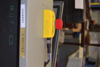
3 Why do you need an Emergency stop? So that anyone shall be able to stop a machine during a machine break-down or if someone is in danger. How do I recognise an E-stop? E-stop buttons shall according to relevant standards be red with a yellow background. n emergency stop grab wire shall be red for high visibility. sign that indicates the location of the E-stop shall be green with a white picture and possibly with text in the local country's language. How shall an E-stop stop the machine? n E-stop shall stop the machine as quickly as possible. To obtain a quick stop one either removes the power directly or one lets a frequency converter 'run down' and afterwards after a little delay, remove the power. n E-stop shall not create other hazards. Therefore a risk analysis must be made for the E-stop to be correctly connected. From 00//EC, clause This device must: - have clearly identifiable, clearly visible and quickly accessible control devices, - stop the hazardous process as quickly as possible, without creating additional risks, - where necessary, trigger or permit the triggering of certain safeguard movements.... Requirements for E-stops are stated in the following standards and regulations 00//EC The Machinery Directive Clause... in nnex gives requirements for the emergency stop function for new machines). See also clause.. Control devices. (see chapter Standard and Regulations ) Council Directive 89//EEC (with amendments) concerning the minimum safety and health requirements for the use of work equipment by workers at work Clause. gives the requirements for the emergency stop function for older machines. See also clause.. (see chapter Standard and Regulations ) EN ISO 80 Safety of machinery Emergency stop Principles for design harmonized standard that gives technical specifications for the requirements in the Machinery Directive. Could also be used for older machinery. EN 00- Safety of Machinery - Electrical equipment of machines Part : General requirements. Harmonized standard that gives requirements for the electrical equipment of machinery including the emergency stop actuator/function. Se clauses 9.. and 9... :


4 Emergency stop for enclosure installation INC pproval: pplication: CERTIFIED BY Emergency push button for installation in cabinets dvantages: Terminal blocks Emergency push button up to cat. /PL e acc. to EN ISO 89- Only mm's construction depth With LED info in print Push button IP, connector IP0 vailable as safety stop (black push button) 7 INC is an emergency stop designed for installation in. mm holes on cabinets. INC has potential free contacts for connection to safety relays. The connection is made in cabinets via a removable terminal which also have excellent measuring points. Inca is also available with a black pushbutton and used as a safety stop. See section on safety stops. In the emergency stop button there is a LED that displays current status on: Green = everything ok Red = this emergency push button has been pressed Off = a unit earlier in the circuit is affected 8 9 +V IQ 0 pulse I RT (+) S S () S S S INC Yellow front ring and emergency stop signs for emergency stop. 0 :
5 Emergency stop for enclosure installation INC Tina pproval: CERTIFIED BY pplication: Emergency push button for installation in cabinets dvantages: Terminal blocks Emergency push button up to cat. /PL e acc. to EN ISO 89- Only mm's construction depth With LED info in push button Info output (Inca Tina) Push button IP, connector IP0 vailable as safety stop (black push button) INC Tina is an emergency stop designed for installation in. mm holes in equipment cabinets. In addition to the INC version, "INC Tina" is also available with electronic adjustment of the dynamic safety loop for connection to the Vital and units. The connection is made in equipment cabinets via a removable terminal block which also has marked measuring points. Inca Tina is also available with black push button and is used in this case as a safety stop. See section on safety stops. The emergency stop button has a LED that displays the current status: Green = everything is OK Red = this emergency stop has been pressed. Flashing red/green = a protection device earlier in the loop has been actuated. Vital INC Tina +V IQ 0 pulse B T B R Yellow front ring and emergency stop signs for emergency stop. Info PLC :
6 Technical data - INC /INC Tina Manufacturer: rticle no./ordering data: INC INC Tina Impact resistance (half sinusoidal) Vibration resistance (sinusoidal) Climate resistance Damp heat, cyclical Damp heat, sustained Dry heat Cooling Salt mist Level of safety: Cat. /PL e Category SIL SIL PFH D : INC INC Tina: Colour: Weight: Size: Material: Temperature: Enclosure classification Installation: B/Jokab Safety, Sweden TL000R000 TL000R0000 Max. 0m/s², pulse width ms, -axis, acc. to EN IEC Max. 0 m/s² at 0 Hz 00 Hz, 0 cycles, axis, acc. to EN IEC hours, + C / 97%, + C / 9 % relative humidity, as per EN IEC days, +0 C / 9 % relative humidity, as per EN IEC hours, +70 C, as per EN IEC hours, -0 C, as per EN IEC hours, + C in a chemical solution with NaCl as per EN IEC EN ISO 89- EN 9- EN 0 IEC/EN PFH D :,0 0-0 PFH D :. 0-9 Yellow, red and black pprox. grams See drawing Polyamide P, Macromelt, Polybutylenterephthalate PBT UL 9 V0-0 C to + C (operation), -0 C to +70 C (storage) Print: IP, Connector: IP0, mm Emergency stop LEDs: INC : Green: Safety device OK. Not lit: unit earlier in the circuit is affected. Red: This emergency stop has been pressed. INC Tina: Green: Safety device OK, safety circuit OK Flashing: Safety device OK, safety circuit previously broken. Red: This button is pressed in, and the safety circuit is broken. Operating voltage (LED): Current consumption (LED): Emergency stop button Operating force: Operating movement: Contact material: INC : VDC INC Tina: VDC +% -% INC : m INC Tina: 7 m ± N pprox. mm to locked position Gold-plated silver alloy Minimum current: INC : 0 m, 0 VDC/0 VC INC Tina: Maximum current: INC : VDC INC Tina: Mechanical life: > operations Standards: EN 00, EN & - EN ISO 80 ccessories: Front ring yellow for INC TL000R000 Emergency stop sign S D F,,mm TL000R000 Emergency stop sign E FT,,mm TL000R000 Conformity: 00//EG EN 9-, EN ISO 89-, EN 0, EN 00-, EN 9-, IEC 0-, EN 000--, EN 000--, EN 097--, EN :
 vailable for S-i In order to fulfil the need for a small and easy to install")
7 Emergency stop with indication Smile pprovals; CERTIFIED BY pplication: To stop a machine or a process Features: Smile - small and cost effective E-stop Emergency push button up to cat. /PL e acc. to EN ISO 89- With LED info in push button Robust Push button IP, housing IP7 vailable as safety stop (black push button) vailable for S-i In order to fulfil the need for a small and easy to install E-stop, Smile has been developed. The size of the device makes it possible to be installed wherever you want. With M connection/s or cable and centralised mounting holes Smile is very easy to install, especially on aluminium extrusions. Smile is available for E-stops in both dynamic and static safety circuits i.e. for interfacing to Vital/ and Safety relays. Each version is available with either one or two M connections or cable. t the top of Smile, a LED shows the current status as: green = protection OK, red = this emergency stop has been pressed and if the LED is off, an emergency stop earlier in the loop has been actuated. Smile is also available with black push button and is used as a safety stop. See section on safety stops. Smile emergency stop has six different variants:. Smile 0E has a m cable connected through the base of the unit.. Smile 0EK has four m short connecting leads through the base of the unit. No LED.. Smile E has a five-pole M connector on one end of the unit. lso available with S-i.. Smile E has two five-pole M connectors, one on each end of the unit.. Smile ER has one -pole M connector at one end.. Smile ER has two -pole M connectors at each end. Smile E adapted for S-i The Smile E also comes in a version adapted for direct attachment to the S-i bus. :
8 Connection examples Smile Smile 0E can be connected to either or a safety relay. Single channel example with LED indication. Safety category. The connection cable exits from underneath the unit. safety PLC +V (+) S Safety relay E.g. RT, RT9 Smile 0E Smile E can be connected to either or a safety relay. Single channel example with LED indication. Safety category. Connection via M connector. safety PLC +V Safety relay E.g. RT, RT9 Smile E can be connected to either or a safety relay. Single channel example with LED indication. Safety category. Connection via M connector + termination connector. S S (+) S S S Smile E Smile 0E can be connected to either or a safety relay. Two channel example with LED indication. Safety circuit category. safety PLC +V IQ 0 -pulse I (+) S Safety relay E.g. RT, RT9 Smile 0E Smile E can be connected to either or a safety relay. Two channel example with LED indication. Safety circuit category. Connection via M connector. safety PLC +V IQ 0 -pulse I Safety relay E.g. RT, RT9 S () S (+) S S Smile E can be connected to either or a safety relay. Two channel example with LED indication. Safety circuit category. Connection via M connector + termination connector. S S () S S S Smile E 7 8 safety PLC +V (+) S Safety relay E.g. RT, RT9 S S Smile E JST safety PLC +V IQ 0 -pulse I Safety relay E.g. RT, RT9 (+) S S () S S S Smile E JST 9 0 Smile E can be connected to either or a safety relay. Two channel serial connection example with LED indication. Safety circuit category. Connection via M connectors. Connection is made here without a termination device for Smile E (C), this unit is reconnected to the /safety relay via a separate cable. You can also use JST as a termination device after SmileE (C). safety PLC +V IQ 0 -pulse I +V IQ 0 -pulse I Safety relay E.g. RT, RT9 (+) S S () S S S (+) S S () S S S Smile E Smile E Smile E B B C C :7
 completes the circuit without the need for a termination connector (JST) or return cable.")
 S S S Smile E Smile E Smile E E-Stop Button status LED Indication The table shows the LED indication status of the E-Stop B C B C buttons from the example shown in above example.")
9 Connection examples Smile Smile E and E can be connected to either or safety relay. Two channel example with LED indication. Safety circuit category. Connection via M connectors. Note that there is no termination connector as the Smile E (C) completes the circuit without the need for a termination connector (JST) or return cable. safety PLC +V IQ 0 -pulse I (+) S Safety relay E.g. RT, RT9 S () S S S Smile E Smile E Smile E E-Stop Button status LED Indication The table shows the LED indication status of the E-Stop B C B C buttons from the example shown in above example. R R R G G G R R D G G Rd = Smile E R D R G Rd B B = Smile E R D D G Rd B C = Smile E R = Released D R R Rd B B D = Depressed D R D Rd B B G = Green light from the top of the button D D R Rd B B Rd = Red light from the top of the button D D D Rd B B Termination B = Blank, no light device JST Smile 0E/E/E are like any other emergency stops when to the LED indication is not connected. This means that any suitable Safety PLC or safety relay can be used. If the LED indication is used, the voltage between Pin (+) and Pin (-) should be between VDC. The following examples show connections to Safety PLC and Safety relay. B C Single channel PLC connection Two channel Safety relay connection Output Output PLC Safety Relay Output Input Input Smile E Input Smile E Brown White Blue Black Grey Smile 0E Brown White Black Grey Smile 0EK The cable is connected to Smile 0E via the lid at the back.. Input. Input. 0 VDC (to be connected only if LED indication is required). Output. Output Brown White Blue Black Grey Smile E (R) Brown White Blue Black Grey The leads are connected to Smile 0EK via the lid at the back. No LED connection. Brown Input White Input Black Output Grey Output Smile E (R) Brown White Blue Black Grey. Input. Input. 0 VDC (to be connected only if LED indication is required). Output. Output. Input. Input. 0 VDC (to be connected only if LED indication is required). Output, feedback. Output, feedback. Output. Output. 0 VDC. Input, feedback. Input, feedback :8
10 Technical data Smile Manufacturer: rticle number/ ordering data: Smile 0E with m cable Smile 0EK with short connecting leads (No LED connection) Smile E with M male connector Smile E with male and female M connectors Smile ER Smile ER JST termination for Smile. Smile E S-i Note. There are versions for dynamic technology (with Tina). Impact resistance (half sinusoidal) Vibration resistance (sinusoidal) Climate resistance Damp heat, cyclical Damp heat, sustained Dry heat Cooling Salt mist B/Jokab Safety, Sweden TL000R000 TL000R000 TL000R0000 TL000R000 TL000R000 TL000R000 TL000R00 TL000R0000 max. 0 m/s, pulse width ms, -axis, as per EN IEC max. 0 m/s at 0 Hz, 0 cycles, -axis, as per EN IEC hours, + C / 97%, + C / 9 % relative humidity, as per EN IEC days, +0 C / 9 % relative humidity, as per EN IEC hours, +70 C, as per EN IEC hours, -0 C, as per EN IEC hours, + C in a chemical solution with NaCl as per EN IEC Level of safety: IEC/EN SIL PFH D :,0E-0 Colour: Yellow, red and black Weight: pprox. grams Size: Length: 8 mm + M contact(s) (. mm each) Width: 0 mm Height: mm Material: Polyamide P, Macromelt, Polybutylentere phthalate PBT, Polypropylene PP, UL 9 V0 mbient temperature: -0 C to + C (operation), -0 C to +70 C (stock) Protection class: IP Mounting: Two M recessed hexagon head screws, L mm. Hole cc: mm LED on E-Stop: Green: Safety device ok, Safety circuit closed Off: Safety circuit broken (When an E-Stop is depressed all following units in the circuit lose the LED function). Red: Safety device actuator depressed and Safety circuit broken. Input voltage (LED): 7-7 VDC ripple ±0% (LED supply voltage) Current consumption (LED): m E-Stop button ctuating force: ± N ctuator travel: pprox. mm to latch Material, contacts: Silver alloy gold plated Min current: 0 m 0 VDC/ 0 VC Max current: VDC Life, mechanical: > operationer ccessories: Emergency stop button S D F,,mm TL000R0700 Emergency stop button E F T,,mm TL000R0800 Conformity: EN ISO 80, EN 00, EN & - Sign for emergency stop :9


11 Emergency stop with indication Smile Tina pprovals: CERTIFIED BY pplication: To stop a machine or a process Features: Smile Tina - small and cost effective E-stop In order to fulfil the need for a small and easy to install E-stop, Smile has been developed. The size of the device makes it possible to be installed wherever you want. With M connections or cable and centralised mounting holes Smile is very easy to install, especially on aluminium extrusions. Smile is available for E-stops in both dynamic and static safety circuits i.e. for interfacing to Vital system/ safety PLC and Safety relays. Each version is available with either one or two M connections or cable. Two M connectors are used to enable the connection of E-stops in series, which is often used with dynamic safety circuits fulfilling safety category. In the top of the Smile Tina E-stop unit, LEDs show the actual status according to the dynamic system: Green = everything is OK, Red = E-stop activated. Flashing Red/Green = Stop activated from another preceding device. Smile is also available with black push button and used as a safety stop. See section on safety stops. The Smile Tina emergency stop is available in four versions:. Smile 0E Tina has a m cable connected via the base of the unit.. Smile E Tina has a five-pole M connector on the end of the unit for connecting the Jokab Safety cable.. Smile E Tina has two five-pole M connectors, one on each end of the unit for connecting the Jokab Safety cable.. Smile ER Tina has one -pole M connector at one end for connection of cable from Jokab Safety. Emergency push button up to cat. /PL e acc. to EN ISO 89- Light grids, emergency stop and Eden in the same safety loop together with Vital or gives cat. /PL e acc. to EN ISO 89- With LED indication on push button Robust Info-signal from each emergency stop Push button IP, housing IP7 vailable as safety stop (black push button) :0
12 Connection examples Smile Tina Smile 0E Tina can be connected to either a or Vital system. Safety circuit category with LED indication/information. The connection cable exits from underneath the unit. IQ0 Vital T R Smile 0E Tina Smile E Tina can be connected to either a or Vital system. Safety circuit category with LED indication/information. Connection via M connectors. The circuit below shows three Smile E Tina units connected in series via connection terminals in the electrical cabinet. Electrical cabinet IQ0 Vital T R Connection termination Smile E Tina Smile E Tina Smile E Tina B C 7 8 Smile E Tina can be connected to either a or Vital system. Safety circuit category with LED indication/information. Connection via M connectors. The circuit below shows three Smile E Tina units and one Eden connected in series via a Tina connection block. IQ0 Vital Tina T R Smile E Tina Smile E Tina Smile E Tina B C 9 0 Eden = dam & Eva :
13 Connection examples Smile Tina E-Stop Button status Information output signal B C B C R R R H H H R R D H H L R D R H L H R D D H L L D R R L H H D R D L H L D D R L L H D D D L L L The table shows the information output signal status from each of the Smile E Tina units in the previous connection examples. In the example showing connection with an Eden sensor, the Eden status information signal acts in the same way as the Smile Tina E units. The status information signal can be connected to e.g. PLC input. Note. The information signal must not be used as a safety signal. The signal should only be used to indicate the status of connected devices. = Smile E Tina B = Smile E Tina C = Smile E Tina R = Released Smile E can be connected to either a or Vital system. Safety circuit category with LED indication/information. Connection via M connectors. The last Smile E Tina unit feeds the dynamic signal back to the /Vital. D = Depressed H = High (i.e. supply voltage) L = Low (= 0 VDC) B C IQ0 Vital T R Smile E Tina Smile E Tina Smile E Tina E-Stop Button status LED Indication B C B C R R R G G G R R D G G Rd R D R G Rd F R D D G Rd Rd D R R Rd F F D R D Rd F Rd D D R Rd Rd F D D D Rd Rd Rd The table shows the LED indication status of the E-Stop buttons in the previous connection examples, where three Smile 0 E, Smile E or E Tina units are connected in series. = Smile 0// E Tina B = Smile 0// E Tina C = Smile 0// E Tina R = Released D = Depressed G = Green light from the top of the button Rd = Red light from the top of the button F = Flashes between green and red light Smile E can be connected to either a or Vital system. Safety circuit category with LED indication/information. Connection via M connectors. The circuit shows two Smile E Tina s, one Eden sensor and one Focus Light Curtain connected in series. Eden = dam & Eva Focus IQ0 Vital T R Smile E Tina Smile E Tina M- M- M-B Tina 0 Brown White Blue Black Grey + - Smile 0E Tina. Input voltage,7-7 VDC ripple+/- 0%. Dynamic input signal. 0 VDC. Dynamic output signal. Information output The connection cable is connected to the Smile 0E Tina unit via the back panel. Brown White Blue Black Grey + - Smile E Tina Brown White Blue Black Grey + - Smile E Tina + - Brown White Blue Black Grey. Input voltage,7-7 VDC ripple+/- 0%. Dynamic input signal. 0 VDC. Dynamic output signal. Information output. Input voltage,7-7 VDC ripple+/- 0%. Dynamic input signal. 0 VDC. Not used. Not used. Output voltage to next unit. Dynamic output signal (To next Smile or to or Vital system). 0 VDC. Not used. Information output :
14 Technical data Smile Tina Manufacturer: rticle number/ ordering data: Smile 0E Tina with m connection cable Smile E Tina with M male connector Smile E Tina with male and female M connectors Smile ER Tina Note. There are versions for use with relay technology (without Tina). Impact resistance (half sinusoidal) Vibration resistance (sinusoidal) Climate resistance Damp heat, cyclical Damp heat, sustained Dry heat Cooling Salt mist Level of safety: IEC/EN SIL PFH D : Colour: Weight: Size: Material: mbient temperature: B/Jokab Safety, Sweden TL0000R000 TL0000R0000 TL0000R000 TL0000R000 max. 0 m/s, pulse width ms, -axis, as per EN IEC max. 0 m/s at 0 Hz, 0 cycles, -axis, as per EN IEC hours, + C / 97%, + C / 9 % relative humidity, as per EN IEC days, +0 C / 9 % relative humidity, as per EN IEC hours, +70 C, as per EN IEC hours, -0 C, as per EN IEC hours, + C in a chemical solution with NaCl as per EN IEC 008--,E-09 Protection class: IP Mounting: Yellow, red and black pprox. grams Length: 8 mm + M contact(s) (.mm each) Width: 0 mm Height: mm Polyamid P, Macromelt, Polybutylenterephthalate PBT, Polypropylen PP, UL 9 V0-0 C to + C (operation) -0 C to +70 C (stock) Two M hexagon socket screws, L mm. Hole centres: mm LED on E-Stop: Time delay: Sign for emergency stop Green: Safety device OK, Safety circuit OK Flashing: Safety device OK, safety circuit broken. Red: Breaks in safety device and safety circuit :. (Two Smile units are equal to three Edens in time delay) Input voltage: 7-7 VDC ripple ±0% Current consumption: Current from information output: E-Stop button ctuating force: ctuator travel: Material, contacts: Life, mechanical: ccessories: Emergency stop sign S D F,.mm Emergency stop sign E F T,.mm 7 m (7m with max. current from information output) 0 m max ± N pprox. mm to latch Silver alloy gold plated > operations TL000R0700 TL000R0800 Conformity: EN ISO 80, EN 00, EN & :


15 Emergency stop with indication Smile S-i pprovals: CERTIFIED BY pplication: To stop a machine or a process Safe input node in S-i systems Features: Smile E S-i is an emergency stop with a built-in dual channel safe S-i input node. The S-i bus and the safety around it is specified by the two organisations S-International ssociation and S-Interface Safety at Work, and is described in publications such as S-Interface The utomatic Solution. Smile E S-i is supplied with 0 V DC from the S-i bus. The recommended connection to the S-i bus is made via a flat cable terminal to M (see Figure), which makes it possible to quickly and easily connect the device to the yellow S-i cable. Smile S-i can also be connected directly to the S-i bus using only two conductors (pins and on the unit's M contact). Smile is also available with black push button and is used in this case as a safety stop. See section on safety stops. Emergency push button up to cat. /PL e acc. to EN ISO 89- Simple connection to S-i bus With LED indication on push button and S-i status indication Robust Push button IP, housing IP7 vailable as safety stop (black push button) :

16 Technical data Smile S-i Manufacturer: rticle number/ ordering data: Smile E S-i B/Jokab Safety, Sweden TL000R0000 S-i data S-i profile S-7.B.0 ddressing M-contact Node address on delivery 0 Response time across the S-i bus ms (+ response time for safety monitor) Pin configuration () S-i + () Not used () S-i () Not used () Not used Voltage supply Output voltage Total current consumption < 0 m 0 V DC from the S-i bus. Tolerance.. V DC. General Enclosure protection class IP mbient temperature - +0 C Dimensions x 0 x 8 (+, mm M contact) (H x B x D) Colour Base: Yellow Emergency stop button (Smile E S-i): Red Safe stop button (Smile S S-i): Black ctuating force ± N ctuating movement Ca mm till lås Mechanical life > operationer PFH D,9x0-9 Safety/Harmonised standards IEC/EN SIL, PFDavr:,9x0 - EN 0 SIL EN ISO 89- Performance level PL e, Category, MTTF d : high EN & - For emergency stop buttons/ safety stop buttons EN ISO 80:008 For emergency stop buttons/ safety stop buttons Certification TÜV Nord Push button control panel LED in emergency stop button LED displays can be individually programmed in the PLC program as shown below. LED in pushbutton Indicator Description Red ON Output bit ON OFF Output bit OFF or Output bit & ON Green ON Output bit ON OFF Output bit OFF or Output bit & ON S-i LED and Fault LED in combination LED pair at the M contact. S-i (Green) Fault (Red) OFF OFF S-i voltage missing ON OFF Normal operation ON ON No data exchange with master Flash ON No data exchange due to address = Smile xxxx-x with one S-i node for four pushbuttons. Smile Exxxx-x with one S-i safety node for e-stop and one S-i node for three pushbuttons. Smile EKxxxx-x with two safety nodes (e-stop and mode selector) and one S-i node for two pushbuttons. :
17 Safety stop Inca and Smile When should I use the safety stop? Safety stops are used to stop the operation of a machine in a safe manner. It must not be used as an emergency stop, but only as a stop for an individual hazardous motion. This is indicated by black push button. Likewise, an emergency stop push button with red push button must not be used as a safety stop. Inca for panel mounting The Inca series is available with black push button and is called Inca S/Inca S Tina. The safety stop is identical to the corresponding emergency stop apart from the black push button. For technical data see the Inca emergency stop. Smile with indication The Smile series is available with black push button and has a similar designation apart from an S in the name instead of E. The safety stops are identical to the corresponding emergency stops apart from the black push button. For technical data see the Smile emergency stop. rticle number TL000R000 TL000R000 Ordering data INC S INC S Tina rticle number Ordering data TL000R0900 Smile S TL000R000 Smile S TL000R00 Smile SR TL0000R000 Smile S Tina TL0000R000 Smile S Tina TL0000R0700 Smile SR Tina TL0000R0800 Smile SR Tina TL000R000 Smile S S-i :


18 Reset button Smile R When do I need reset push button? Smile R/B are reset Push buttons intended to reset safety circuits. Smile R has a connections for the NO-contact and for the LED in the PB. The reset LED is o be turned of after reset of the safety circuit. Smile RB is used together with our Safety Plc in order to reduce the numder of terminals, on terminal is used as both input for the reset as well as output for the LED. 7 Technical data Smile R Manufacturer rticle number/ ordering data Smile R Smile RB Colour Base Pushbutton Material Housing Pushbutton contact B/Jokab Safety, Sweden TL000R0000 TL000R000 yellow blue Polyprobylene PP u mbient temperature Humidity range Protection class Connectors Size Weight Mechanical life Switching reliability C to 8% (with no icing or condensation) IP -pole male M connector 8x0x (LxWxH) + mm for M connector (L) aprox. 0 g operations at 0 m/ VDC 0 x 0 - at m/ VDC Power Supply LED operating voltage LED current consumption Pushbutton operating voltage Pushbutton current consumption Pushbutton rated power VDC (maximum VDC) 0 m at VDC 0 m at VDC Min: V, max: V Min: M, max 00 m Max: 0 mw :7
Emergency stops and safety stops
 Emergency stops and safety stops www.jokabsafety.com Contents Page Why do you need an Emergency stop? : Emergency stop for enclosure installation INC : Emergency stop for enclosure installation INC Tina
Emergency Stops. Shut down all machine functions! Protect machine during breakdown! Meet emergency stop regulations!
 Emergency Stops Shut down all machine functions! Protect machine during breakdown! Meet emergency stop regulations! Why should I use an Emergency Stop?... 9: INCA/INCA Tina Emergency Stop for Enclosure
Original instructions INCA-1 Tina Emergency stop for enclosure installation INCA-1S Tina Safety stop for enclosure installation
 Original instructions INCA-1 Tina Emergency stop for enclosure installation INCA-1S Tina Safety stop for enclosure installation ABB AB / Jokab Safety Varlabergsvägen 11, SE-434 39 Kungsbacka, Sweden www.abb.com/lowvoltage
Safety Light Curtain Orion1 Extended
 Safety Light Curtain Orion1 Extended pprovals: pplication: For finger and hand detection When the light guard should be close to the hazardous zone When muting or blanking are necessary When several devices
Original operating instructions Fail-safe inductive sensor GM504S / / 2010
 Original operating instructions Fail-safe inductive sensor GM504S 704070 / 01 06 / 2010 Contents 1 Preliminary note 3 1.1 Explanation of symbols 3 2 Safety instructions 4 2.1 Safety-related requirements
Original operating instructions Fail-safe inductive sensor GG507S / / 2013
 Original operating instructions Fail-safe inductive sensor GG507S 80005283 / 00 05 / 2013 Contents 1 Preliminary note...3 1.1 Explanation of symbols...3 2 Safety instructions...4 2.1 Safety-related requirements
Accessories. Accessories
 Series 61 16mm 22.5mm 21 x 21mm 21 x 27mm IP65 5 250V INDITOR PUSHUTTON E-STOP KEYLOK SELETOR hoose one component from each of the coloured sections to assemble a complete switch. For other options or
Complete units: Mushroom heads ø 22mm
 Complete units: Mushroom heads ø 22mm MAINTAINED - NON-ILLUMINATED Ø 40 MUSHROOM Push-pull to reset Technical Info (p. 103) Black Bezel Part Number 34.2 Ø 40 Red NC L22DD01-3E01 Red 2 NC L22DD01-3E02 Red
Control Stations ø 22
 Control Stations ø 22 CONTROL STATIONS - NON-ILLUMINATED Technical Info (p. 103) MUSHROOM HEAD Ø 40 - MAINTAINED Push-turn to reset Part Number M16/20 47.9 25.7 Ø 40 Red NC EMERGENCY STOP LBX10510 Red
Complete units: Push-buttons ø 22mm
 Complete units: Push-buttons ø 22mm FLUSH SPRING RETURN - NON-ILLUMINATED Chrome Bezel Part Number Technical Info (p. 103) Black Bezel Part Number 11 Ø 29.9 20.1 19.6 With single position clip Red NC L21AA01-1E01
Electronic Circuit Breaker with reset input ESS20-1..
 Electronic Circuit Breaker with reset input ESS0-.. Description The special device ESS0-.. is a further extension of the product line electronic circuit breakers. Type ESS0-.. has a width of only. mm and
Complete units: Selector switches ø 22mm
 Complete units: Selector switches ø 22mm SELECTOR SWITCHES - NON-ILLUMINATED Technical Info (p. 13) WITH KNOB 2 and 3 positions Chrome Bezel Part Number Black Bezel Part Number Ø 29.9 Maintained positions
Local control stations for Zone 1 and Zone 21. Features. Description
 Local control stations for Zone and Zone Local control stations for Zone and Zone Features The right size/material enclosure Optimum functionality thanks to the great variety of components Customised planning
Datasheet - PROTECT-IE-02
 Print - Create PDF - Create EXCEL file 20.04.2011-18:28:57h Datasheet - PROTECT-IE-02 Input expander / PROTECT-IE Input expander Input for up to 4 sensors per interface e.g.: magnetic safety switches type
Operator Heads: ø 22mm
 Operator Heads: ø 22mm ONE-PIECE PILOT LIGHTS Technical Info (p. 103) SUPPLIED WITHOUT BULB Part Number L20SA40 14.3 44.1 Ø 29.8 Ø 20.2 Ø 22 Ø 29.5 1 to 6 6 Ribbed Lens Clear Smooth Lens With text or symbol
Operator Heads: ø 22mm
 Operator Heads: ø 22mm SPRING RETURN - NON-ILLUMINATED Technical Info (p. 103) FLUSH-FLUSH Twin touch Chrome Bezel Part Number Black Bezel Part Number 12.3 11 53.9 29.9 With International Symbols Green
Digital Input Output Module 24 V for Ex n Zone 2 Series 9472/35
 www.stahl.de > 16 channels can be adjusted in pairs as digital inputs or outputs > Suitable for NAMUR proximity switches, 3-wire PNP proximity switches, contacts and solenoid valves (24 V / 0.5 A). > Up
02/11/2015
 Standstill monitoring KSW3-JS Part number 85102331 Function "Stillstand detection without sensors" Independent of rotation direction Security with redundancy and feedback circuit 3 forcibly guided "NO"
Model Number Structure
 General-purpose Relay MK-I/-S Electromechanical Relays Exceptionally Reliable General-purpose Relay Features Mechanical Indicator/Push Button Breaks relatively large load currents despite small size. Long
Acceleration sensors With relay output for limit monitoring Analog / CANopen
 Features Acceleration sensor / analog / CANopen Up to two relay outputs for limit monitoring 3 axes detection, MEMS based Measuring range ±2 g Connection: connector M12, 12-pin Offshore capability (plastic
02/11/2015
 Emergency stop and safety guard monitoring 1 channel KNAC3-YS Part number 85103035 "Emergency stop" & "Gate monitoring" functions Single channel operation Security with redundancy and feedback circuit
Separate units: Blocks
 Separate units: Blocks LED BLOCKS Technical Info (p. 103) SCREW TERMINALS Part Number 3.8 LED 19.7 20.1 X1 X2 33EARL 9.9 19.7 21.5 18.2 12/24 V White Red Green Blue Yellow 33EAWL 33EARL 33EAGL 33EABL 33EAYL
HMI Components. Series. Front mounting Glass mounting. Illuminated pushbutton Indicator Warning indicator Emergency call button. Public transportation
 dition 09/015 HMI Components 57 Series Characteristics The Series 57 is especially suited for: ront mounting Glass mounting It is characterised by a extra large operating area, two independently illuminated
Online data sheet UE48-3OS2D2 UE48-3OS SAFETY RELAYS
 Online data sheet UE48-3OS2D2 UE48-3OS A B C D E F Illustration may differ Ordering information Type Part no. UE48-3OS2D2 6025089 Other models and accessories www.sick.com/ue48-3os H I J K L M N O P Q
Inductive sensor slot-type SI2-K08-AP7
 SI2-K08-AP7 Slot sensor, height 8 mm Plastic, polypropylene Mechanical end stop, removable, for analog pointer instruments 3-wire DC, 10 30 VDC NO contact, PNP output Cable connection Wiring diagram Type
Online data sheet UE48-2OS2D2 UE48-2OS SAFETY RELAYS
 Online data sheet UE48-2OS2D2 UE48-2OS A B C D E F Illustration may differ Ordering information Type Part no. UE48-2OS2D2 6024915 Other models and accessories www.sick.com/ue48-2os H I J K L M N O P Q
PHOENIX CONTACT
 Electronic circuit breaker CLIPLINE Data sheet 102898_en_03 PHOENIX CONTACT 2010-12-17 1 Description The electronic circuit breaker can be used in applications that cover all aspects of the switched-mode
02/11/2015
 Two-hand safety relays KZH3-YS Part number 85102632 "Two-hand" safety function in with two push buttons Inputs for two switches with double contacts (1 NO and 1 NC for each) Security with redundancy and
Original operating instructions Fail-safe inductive sensor GM705S
 Original operating instructions Fail-safe inductive sensor GM705S 80236832 / 00 09 / 2016 Contents 1 Preliminary note...3 1.1 Symbols used...3 1.2 Warning signs used...3 2 Safety instructions...4 2.1 Safety-related
PD140FNT60QMU-02C. Through Beam. Main features. Description
 Through eam Description The PD140 sensor consists of an emitter, which sends out invisible, infrared light, and a receiver, capable of detecting the light from the emitter. The sensor is encapsulated in
Safety light curtain to safeguard the hinge edge IMPORTANT NOTE
 Installation and Operation Manual CEDES MicroRay Safety light curtain to safeguard the hinge edge English EN 12978 EN 13849-1 IMPORTANT NOTE FOLLOW THE INSTRUCTIONS GIVEN IN THIS MANUAL CAREFULLY. FAILURE
New Products Catalogue 2009 Safety Relays ESR5
 www.moeller.net New Products Catalogue 2009 Safety Relays ESR5 u Description Functional safety on machines monitoring with safety relays ESR5 Emergency-stop circuits Monitoring of movable guards with guard
OMRON MK-I / -S RELAY
 Issued April 0 0 DATA SHEET OMRON MK-I / -S RELAY Based on OMRON Datasheet General-purpose Relay MK-I/-S 0 Exceptionally Reliable General-purpose Relay Features Mechanical Indicator/Push Button Breaks
PCB Relay SPST-NO G6CU-1117P-US G6CU-1114P-US G6CU-1117C-US G6CU-1114C-US SPST-NO + SPST- G6CU-2117P-US G6CU-2114P-US G6CU-2117C-US G6CU-2114C-US
 PCB Relay SPST-NO Type Breaks 10-A Loads; SPST-NO + SPST-NC Type Breaks 8-A Load Compact: 20 15 10 mm (L W H). Low power consumption: 200 mw. Flux protection or fully sealed construction available. Unique
General-purpose Relay
 General-purpose Relay Exceptionally Reliable General-purpose Relay Features Mechanical Indicator/Push Button Breaks relatively large load currents despite small size. Long life (minimum 0,000 electrical
PCB Relay. Ordering Information. SPST-NO Type Breaks 10-A Loads; SPST-NO + SPST-NC Type Breaks 8-A Load
 PCB Relay SPST-NO Type Breaks 10-A Loads; SPST-NO + SPST-NC Type Breaks -A Load Compact: 20 x 15 x 10 mm (L x W x H). Low power consumption: 200 mw. Flux protection or plastic-sealed construction available.
PHOENIX CONTACT - 09/2009
 Electronic miniature circuit-breaker CLIPLINE Data sheet 03906_en_0 PHOENIX CONTACT - 09/2009 Description The EC-E... electronic miniature circuit-breaker selectively protects all 24 V DC load circuits
General-purpose Relay
 General-purpose Relay Exceptionally Reliable General-purpose Relay Features Mechanical Indicator/Push Button Breaks relatively large load currents despite small size. Long life (minimum 0,000 electrical
E-STOP relays, safety gate monitors
 Up to Category 2, EN 954-1 Unit features Positive-guided relay outputs: 2 safety contacts (N/O), instantaneous Connection options for: E-STOP pushbutton Reset button LED indicator for: Switch status channel
02/11/2015
 Emergency stop and safety guard monitoring 2 channels KNE3-YS Part number 85102436 "Emergency stop" & "Safety gates monitoring" functions Single and 2-channel operation Security with redundancy and feedback
The Best Relaytion. Cradle Relay N Rev. B EC-JM ECOC: JM10 1. Aug. 04
 The Best Relaytion Cradle Relay N 108-98012 Rev. B EC-JM00-0009-03 ECOC: JM10 1. Aug. 04 PCB, hand solder or plug-in relays, for DC operation, non-polarized, non-latching Features Multi purpose relay highly
* Short-circuit detection at On pushbutton. Applications. Indication. S M6801_a S11 A3 S12 S21 S23 S22 S (+)
") Safety technique Emergency stop module BO 5988 safemaster 0221562 Function diagram Pushbutton on Mains or emergencystop () K1 According to EC Directive for machines 98/37/EG According to IEC/E 60204-1
Safety technique Emergency stop module BO 5988 safemaster 0221562 Function diagram Pushbutton on Mains or emergencystop () K1 According to EC Directive for machines 98/37/EG According to IEC/E 60204-1
Original operating instructions Fail-safe inductive sensor GG507S
 Original operating instructions Fail-safe inductive sensor GG507S 80236827 / 00 09 / 2016 Contents 1 Preliminary note...3 1.1 Symbols used...3 1.2 Warning signs used...3 2 Safety instructions...4 2.1 Safety-related
Safety detection solutions Preventa
 Characteristics Light curtain type XUS LPpppp Environmental characteristics Conformity to standards ANSI/RIA R15.06, ANSI B11:19-1990, OSHA 1910.217(C), OSHA 1910.212, EN/IEC 61496-1-2 for type 4 ESPE
Incremental hollow shaft encoder BRIH EcoMag
 Incremental hollow shaft encoder BRIH EcoMag features miniaturized hollow shaft encoder with wide pulse range radial cable connection or connector end shaft mounting up to mm general data voltage supply
The Best Relaytion. Cradle Relay W Rev. B EC-JM ECOC: JM10 1. Aug. 04
 The Best Relaytion Cradle Relay W 08-9803 Rev. B EC-JM00-0009-03 ECOC: JM0. Aug. 0 Hand solder and plug-in relay, for AC operation, non-polarized, non-latching Features highly reliable great variety of
Shear beam With thin-film technology from 2 kn Models F3301, F33C1, F33S1
 Force Shear beam With thin-film technology from 2 kn Models F3301, F33C1, F33S1 Rated force From 0...2 kn Applications Industrial weighing technology Machine building and plant construction, manufacturing
NSD Safety Mat Controller Modules Both Modules are compliant to OSHA & ANSI Standards - EN ISO EN EN 81-1 EN NSD VDC
 Datasheet NSD Safety Mat Controller Modules Both Modules are compliant to OSHA & ANSI Standards - EN ISO 13849-1 EN 62061 EN 81-1 EN 50156-1 Approvals NSD-3580 24 VDC NSD-3590 115 TO 230 VAC Technical
LINETRAXX VMD460-NA. Network and system protection (NS protection) for monitoring the power feed-in of power generation systems
 for monitoring the power feed-in of power generation systems") LIETRAXX -A etwork and system protection (S protection) for monitoring the power feed-in of power generation systems -A_D00001_01_D_XXE/09.2015 LIETRAXX -A etwork and system protection (S protection) for
LIETRAXX -A etwork and system protection (S protection) for monitoring the power feed-in of power generation systems -A_D00001_01_D_XXE/09.2015 LIETRAXX -A etwork and system protection (S protection) for
Product Data Sheet 3252J/2H3PU
 3252J/2H3PU INDEX 1 General... 3 2 Mechanics... 3 2.1 General... 3 2.2 Connections... 3 3 Operating Data... 5 3.1 Operating Data - Electrical Interface - Input... 5 3.2 Electrical Operating Data... 7 3.3
Pressure transmitter for mobile hydraulic applications With output signals CANopen and J1939
 Electronic pressure measurement Pressure transmitter for mobile hydraulic applications With output signals CNopen and J1939 Model MHC-1 WIK data sheet PE 81.49 pplications Construction machinery gricultural
CMM System - Encapsulated Modules
 CMM System - Encapsulated Modules Bearing Monitoring BMM-40 BDM-40 BMM-42 BDM-42 DMM-13 DMM-12 SPM 40000 SPM 42000 45011-L (max. 4 m) 45011-L (max.100 m) VMM-14/15 VMM-20/21 VDM-14/15 VDM-20/21 90296-L
Safety Technique. SAFEMASTER Emergency Stop Module With Time Delay BH 5928, BI 5928
 Safety Technique SAFEMASTER Emergency Stop Module With Time Delay BH 5928, BI 5928 0226419 BH 5928 BI 5928 Function Diagram According to - Performance Level (PL) e and category 4 to E ISO 13849-1 2008
Catalogue 1SFC en, Edition 3 November 2003 Supersedes Catalogue 1SFC en, Edition 2 November Arc Guard System TVOC
 Catalogue 1SFC 266006-en, Edition 3 November 2003 Supersedes Catalogue 1SFC 266006-en, Edition 2 November 2000 Arc Guard System TVOC System units The two units of the are used as below: Approvals 1. with
ACTUATOR LA36 PRODUCT DATA SHEET
 PRODUCT DATA SHEET ACTUATOR LA36 Features: 12, 24 or 36 V DC Permanent magnetic motor with resetable thermal overload protection Max. thrust 17 N, 26 N, 45 N or 68 N depending on gear ratio and spindle
Online data sheet UE43-3AR3D2 UE43-3AR SAFETY RELAYS
 Online data sheet UE43-3AR3D2 UE43-3AR A B C D E F Illustration may differ Detailed technical data Ordering information Type Part no. UE43-3AR3D2 6034568 Other models and accessories www.sick.com/ue43-3ar
Type Sealing Poles Contacts Rated voltage Model 5PST-NO, SPST-NC 24 VDC *1
 Slim Relays with Forcibly Guided Contacts Conforming to EN Standards EN50205 Class A, approved by VDE. Ideal for use in safety circuits in production machinery. Four-pole and six-pole Relays are available.
Diffuse reflection light scanner with background suppression. Dimensioned drawing. Electrical connection. see remarks!
 Dimensioned drawing 1 5mm 1-3 V D Scanner with adjustable background suppression Two switching points Individual adaptation to applications by means of programming and diagnosis software Universal sensor
21 VA (l max 20 5 ms) Connection Cable 1 m, 4 x 0.75 mm 2 Functional data Factory settings Variable Setting Torque Inhibiting torque
 Connection Cable 1 m, 4 x 0.75 mm 2 Functional data Factory settings Variable Setting Torque Inhibiting torque") echnical data sheet GK4A- Communicative SuperCap rotary actuator with emergency setting function and extended functionalities for adjusting air dampers in ventilation and air-conditioning systems for building
echnical data sheet GK4A- Communicative SuperCap rotary actuator with emergency setting function and extended functionalities for adjusting air dampers in ventilation and air-conditioning systems for building
Electronic Circuit Breaker ESS20-0..
 Description Electronic circuit breaker type ES-0.. is designed to ensure selective disconnection of individual loads in systems which are powered by a DC 4 V switch-mode power supply. DC 4 V power supplies,
PHOENIX CONTACT
 Selective circuit breaker CLIPLINE Data sheet 100464_en_05 PHOENIX CONTACT 2009-11-17 1 Description The electronic circuit breaker, which has a design width of just 12.5 mm, selectively protects all 24
DB 112 B. Double Sheet Testing Unit TECHNICAL DESCRIPTION. en / We reserve the right to. make technical changes
 en 03-2014/06 50126540 We reserve the right to make technical changes DB 112 B Double Sheet Testing Unit TECHNICAL DESCRIPTION 2014 Leuze electronic GmbH + Co. KG In der Braike 1 D-73277 Owen / Germany
Two-way Action Test Button (Models with Lockable Test Button) For Momentary Operation
 For Momentary Operation") General Purpose Relays MKS Exceptionally Reliable General Purpose Relay now available with Lockable Test Button IEC Rating of A 0 V AC 0/0 Hz, General use 100,000 cycles. Mechanical indicator standard
General Purpose Relays MKS Exceptionally Reliable General Purpose Relay now available with Lockable Test Button IEC Rating of A 0 V AC 0/0 Hz, General use 100,000 cycles. Mechanical indicator standard
Actuator LA12 PRODUCT DATA SHEET
 PRODUCT DATA SHEET Actuator LA12 Thanks to its small size and outstanding performance, the actuator LA12 provides a practical and cost-effective alternative to small-scale traditional hydraulic and pneumatic
MK-S (New Models) General-purpose Relays. New Super MK Relays. Models with Latching Lever Added to the Series. Features. Model Number Structure
 General-purpose Relays. New Super MK Relays. Models with Latching Lever Added to the Series. Features. Model Number Structure") General-purpose Relays MK-S (New Models) CSM_MK-S_DS_E 1 New Super MK Relays. Latching Lever Added to the Series. Same mounting and internal wiring as the previous Super MK Relays Built-in mechanical indicator
General-purpose Relays MK-S (New Models) CSM_MK-S_DS_E 1 New Super MK Relays. Latching Lever Added to the Series. Same mounting and internal wiring as the previous Super MK Relays Built-in mechanical indicator
SAFETY LIGHT CURTAINS
 SAFETY LIGHT CURTAINS SOLID-, SOLID-E A reliable and interference-proof safety sensor system is a prerequisite for high system availability and achievement of production targets. At the same time the increasing
Absolute Encoders Singleturn
 The absolute singleturn encoders Sendix 5853 SIL and 5873 SIL are perfectly suited for use in safety-related applications up to SIL3 according to DIN EN ISO 6800-5- or PLe to DIN EN ISO 3849. The extra
maxon document number:
 maxon document number: 791272-04 1 Table of contents... 2 2 Table of figures... 3 3 Introduction... 4 4 How to use this guide... 4 5 Safety Instructions... 5 6 Performance Data... 6 6.1 Motor data... 6
Digital Input Module 24 V Ex n Inputs, 16 Channels Series 9471
 > 16 channels for active 0 / 24 V signals > Zone 2 / Division 2 version for connection of circuits acc. to Ex nl, Ex na, Nonincendive and Non-Ex > Galvanic separation between inputs and system > Two channels
Ratchet Relay. Ordering Information. Unique Ratchet Mechanism Assures Positive Alternate Transfer/Switching Operation. G4Q-jjjj
 Ratchet Relay Unique Ratchet Mechanism Assures Positive Alternate Transfer/Switching Operation Each contact in the double-pole contact mechanism performs alternate make-brake operation at each pulse input
Product Information. RCN 2000 RCN 5000 RCN 8000 Absolute Angle Encoders for Safety-Related Applications
 Product Information RCN 2000 RCN 5000 RCN 8000 Absolute Angle Encoders for Safety-Related Applications September 2013 RCN 2000 series Absolute angle encoders for safety-related applications Safe absolute
ORIGINAL INSTRUCTIONS
 FACTORY AUTOMATION ORIGINAL INSTRUCTIONS Safety light grid SLP series The latest version of the General Terms of Supply for Products and Services in the Electronics Industry issued by the German Electrical
Online data sheet MAX48N-31V10K12500 MAX48 LINEAR ENCODERS
 Online data sheet MAX48N-31V10K12500 MAX48 A B C D E F H I J K L M N O P Q R S T Illustration may differ Detailed technical data Safety-related parameters Ordering information Other models and accessories
Temposonics. Magnetostrictive Linear Position Sensors. EP2 Analog Data Sheet
 Temposonics Magnetostrictive Linear Position Sensors EP2 Analog Optimal price- / performance ratio Position measurement with more than one magnet Smooth & compact Temposonics EP2 Analog MEASURING TECHNOLOGY
NEW TOUGHEST WIND SENSORS THE WORLD S 1:2
 F T 74 2 D ATA S H E E T NEW S U R FA C E M O U N T D E S I G N E D F O R I N T E G R AT I O N THE WORLD S TOUGHEST WIND SENSORS WWW.FTTECHNOLOGIES.COM 1:2 PROVEN IT LOOKS DIFFERENT BECAUSE IT IS DIFFERENT
Digital Grid Products. SICAM Fault Sensor Indicator (FSI) The Guardian for your Overhead Line Networks
 The Guardian for your Overhead Line Networks") Digital Grid Products SICAM Fault Sensor Indicator (FSI) The Guardian for your Overhead Line Networks SICAM Fault Sensor Indicator (FSI) System Diagram of FSI and FCG Description SICAM Fault Sensor Indicator
Digital Grid Products SICAM Fault Sensor Indicator (FSI) The Guardian for your Overhead Line Networks SICAM Fault Sensor Indicator (FSI) System Diagram of FSI and FCG Description SICAM Fault Sensor Indicator
Technical data. General specifications. Measurement range min max. 360
 Model Number Features Very small housing High climatic resistance 12 Bit singleturn Analog output Surge and reverse polarity protection Description This absolute rotary encoder with internal magnetic sampling
Temposonics. Magnetostrictive Linear Position Sensors. EP2 IO-Link Data Sheet
 Temposonics Magnetostrictive Linear Position Sensors EP2 IO-Link Flexible mounting Operating temperature up to +75 C (+167 F) Smooth & compact Temposonics EP2 IO-Link MEASURING TECHNOLOGY The absolute,
Operating instructions Fail-safe delay timer AZS About this document. Content
 8 Appendix 8.1 Wiring example...4 8.2 Integral System Diagnostics (ISD)....5 9 EU Declaration of conformity Operating instructions.............pages 1 to 6 Original x.000 / 11.2017 / v.a. - 101126753-
Temposonics. Magnetostrictive Linear Position Sensors. EP2 SSI Data Sheet
 Temposonics Magnetostrictive Linear Position Sensors EP2 SSI Optimal price- / performance ratio Operating temperature up to +75 C (167 F) Smooth & compact MEASURING TECHNOLOGY The absolute, linear position
Temposonics. Magnetostrictive Linear Position Sensors. EP2 CANopen Data Sheet
 Temposonics Magnetostrictive Linear Position Sensors EP2 CANopen Optimal price- / performance ratio Position measurement with more than one magnet Smooth & compact Temposonics EP2 CANopen MEASURING TECHNOLOGY
Type Nominal voltage (V) Code HSV V
 Code HSV V") Speed control Speed control relay - mm Control of overspeed, underspeed, operating rate, stopping Measurement via discrete sensors - -wire PNP or NPN, Namur, voltage 0-0V or volt-free contact type Works
Speed control Speed control relay - mm Control of overspeed, underspeed, operating rate, stopping Measurement via discrete sensors - -wire PNP or NPN, Namur, voltage 0-0V or volt-free contact type Works
PD30CNB25xxPS. Photoelectrics, Background suppression reflective - PointSpot. Main features. Main functions. Description
 Photoelectrics, Background suppression reflective - PointSpot Main features Miniature sensor range The visible red PointSpot light makes alignment very easy Range: 250 mm Sensitivity adjustment by potentiometer
Ordering Information. PCB Relay G6RL. Model Number Legend: Low-profile power relay with maximum switching of 10 A
 PCB Relay G6RL Low-profile power relay with maximum switching of 10 A Low profile: 12.3 mm in height Max. switching capacity: 2,500 VA (NO) IEC 60947-5-1, AC-15, DC13 Clearance and creepage distance: 10
Product Information ECN 424 S EQN 436 S. Absolute Rotary Encoders with DRIVE-CLiQ Interface for Safety-Related Applications
 Product Information ECN 424 S EQN 436 S Absolute Rotary Encoders with DRIVE-CLiQ Interface for Safety-Related Applications December 2016 ECN 424 S, EQN 436 S Rotary encoders for absolute position values
DB 12 B. Double Sheet Testing Unit. Phone: Fax: Web: -
 DB 12 B Double Sheet Testing Unit GB 03-08/08 50104956 Table of contents 1 General information... 2 1.1 Explanation of symbols... 2 1.2 Declaration of conformity... 2 2 Safety notices... 3 2.1 Safety standards...
Laser contrast scanner. Dimensioned drawing
 Laser contrast scanner Dimensioned drawing en 06-2016/08 50110624-03 60mm 10-30 V DC Red light laser transmitter Various teach variants Small light spot adjustment via EasyTune Level adaptation for glossy
Grundfos Direct Sensor
 GRUNDFOS DT OOKLET Grundfos Direct Sensor sensors Grundfos Direct Sensor Table of contents 1. Product introduction 3 Type key 4 2. Relative- sensor, Industry (RPI) 5 RPI / RPI +T general data 5 RPI, 0-0.6
W 23-2: Focussing on what is essential and economic
 Product group W - BGB Photoelectric proximity switch Energ. Photoelectric proximity switch W -: Focussing on what is essential and economic Photoelectric reflex switch The indicator LEDs on the W - offer
Safety Technique. Emergency Stop Module With Time Delay BH 5928, BI 5928
 Safety Technique safemaster Emergency Stop Module With Time Delay BH 5928, BI 5928 0226419 BH 5928 BI 5928 Function Diagram According to - Performance Level (PL) e and category 4 to E ISO 13849-1 2008
 Phase control Single function phase control relay - 7.5 mm Control of -phase networks: phase sequence, total phase failure Multi-voltage from x 08 to x 480 V Controls its own supply voltage True RMS measurement
Technical data. T2-SM230ASR en v Subject to changes / 3. Electrical data Nominal voltage AC
 echnical data sheet SMASR Modulating damper actuator for adjusting air dampers in ventilation and air-conditioning systems for building services installations For air dampers up to approx. 4 m orque Nm
Panther. Installation instructions. Receivers PN-R15-1 PN-R15-2 PN-R15-13 PN-R IM-PN-RX103-A03-EN Language: English (original)
") Panther Installation instructions Receivers IM-PN-RX0-A0-EN Language: English (original) PN-R5- PN-R5-2 PN-R5- PN-R5-4 CONTENTS Chapter : CUSTOMER INFORMATION Chapter 2: FUNCTIONAL SAFETY 6 Chapter : PRODUCT
Panther Installation instructions Receivers IM-PN-RX0-A0-EN Language: English (original) PN-R5- PN-R5-2 PN-R5- PN-R5-4 CONTENTS Chapter : CUSTOMER INFORMATION Chapter 2: FUNCTIONAL SAFETY 6 Chapter : PRODUCT
Portable equipment for insulation fault location for unearthed and earthed systems (IT and TN systems) to be used in conjunction with or without an
 to be used in conjunction with or without an") EDS309 Portable equipment for insulation fault location for unearthed and earthed systems (IT and TN systems) to be used in conjunction with or without an equipment for insulation fault location EDS309x_D00012_00_D_XXEN/05.2015
EDS309 Portable equipment for insulation fault location for unearthed and earthed systems (IT and TN systems) to be used in conjunction with or without an equipment for insulation fault location EDS309x_D00012_00_D_XXEN/05.2015
TECHNICAL PRODUCT DATASHEET
 FORM-ENG-0018 REV A 06-02-03 ISO 9001 CERTIFIED Phone: (352) 629-5020 or 800-533-3569 Fax: (352)-629-2902 SUITABLE FOR OEM DISTRIBUTION ONLY TECHNICAL PRODUCT DATASHEET High Density PDM 21 Output / 10
Process/Mini. English IMPORTANT NOTE. Installation and Operation Manual. General Purpose Light Curtain with 30 mm resolution
 Installation and Operation Manual Process/Mini General Purpose Light Curtain with 30 mm resolution English manufactured under ISO 9001: 2000 IMPORTANT NOTE FOLLOW THE INSTRUCTIONS GIVEN IN THIS MANUAL
E-STOP relays, safety gate monitors
 Unit features Safety features Gertebild ][Bildunterschrift_NOT_Sch.tuer_Licht Safety relay for monitoring E-STOP pushbuttons, safety gates and light beam devices Approvals Gertemerkmale Positive-guided
SINEAX B 811 Power Pack with additional Functions
 SINEA B 8 for intelligent and conventional s, in housing S7 for rail and wall mounting 002 II () G Application The power supply unit SINEA B 8 (Figure ) provides the DC power supply for s and transfers
05/09/2014
 48 x 48 Digital LCD Timer 814 Part number 88857005 Relay output digital timers LCD or LED (815E) Multi-range Multi-voltage 1 or 2 relay outputs Reset function on panel (Timers 815, 815E) Data saved in
XXXX e. X d.. X X X a
 The Heavy Duty incremental encoder type 0H boasts a high degree of ruggedness in a very compact design. Its special construction makes it perfect for all applications in very harsh environments. / RoHS