A Solution of Test, Inspection and Evaluation for Blind Signal Waveform on a Board
|
|
|
- Nigel Wilkins
- 5 years ago
- Views:
Transcription


1 A Solution of Test, Inspection and Evaluation for Blind Signal Waveform on a Board Tatsumi Watabe, Makoto Kawamura, & Hiroyuki Yamakoshi S.E.R. Corporation Conference Ready mm/dd/ BiTS Workshop March 6-9, 2016
2 Purpose Blind signal waveform analysis on the system board by using Signal Probe Socket. Conclusion Got a real signal waveform by introduction S-parameter data of signal probe socket and InfiniiSim performance. 2
3 Agenda 1) What is a blind signal analysis? 2) Signal probe socket! 2-1) YOROI??? 3) Blind signal measurement & data 4) Conclusion & summary 3
4 1) What is a blind signal analysis? 4


5 Blind Signal! 5
6 Blind signal analysis! Timing analysis between DDR and CPU. Measure and confirm a blind signal waveform directly underneath IC package. Define different approach for identification of a failure point when not re-appearance on LSI tester. Qualification of memory and CPU. Moving measurement point by using InfiniiSim. 6


7 Timing analysis Verification Quality control Timing signal & waveform DDR Clock Hold Time Set up Time Write and Read waveform 7


8 Blind signal measurement 1. All signals of 0.8mm pitch device should be accessible for measurement. 2. Support of high- speed signal measurements over 3.5 Gbps. 3. Solderless mount. (Easy to replace the target IC) 8

9 2) Signal Probe Socket! 9


10 Blind signal probing Signal measurement on DVD player 10


11 Blind signal probing Signal probe socket is on a board of DVD player and connected to the oscilloscope. 11


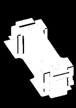
12 Blind signal probing Removed DDR memory and mounted signal probe socket worn YOROI. + 12

13 Setup for DDR memory s blind signal measurement Measurement point Oscilloscope IC socket DDR memory Interposer PCB Other components DVD player PCB assembly Removed DDR 13


14 Signal probe socket basic structure Example PKG: BGA (DDR3 memory) Pitch: 0.8mm Pin count: 96 pin 14


15 Actual performance of DDR memory s signal probe socket Shmoo plot analysis result 1.5Gbps Tester -Verigy -V HSM3600 3Gbps 1.25V 1.425V 1.5V 1.575V 1.75V 15


16 Blind signal probing design structure YOROI structured mount is required for signal probe socket 16


17 SAMURAI wore 2)-1 YOROI??? YOROI for fighting. And signal probe socket also must be. Why? 17


")


18 YOROI structure for signal probe socket (Patent pending) 18


19 Signal probe socket worn YOROI Top plate PCB assembly Probe & Interposer Bottom plate Floating nest (Patent pending) 19
20 Interposer element It influences the measurement of the blind signal waveform. Directly underneath the ball (real signal) Waveform measured directly underneath the ball Waveform at measurement point Equivalent circuit model PCB L C Interposer pattern for measurement (stub) 20


21 3) Blind signal measurement & data 21

22 Testing procedure & method DDR Memory Target is this signal waveform Measurement point DDR Memory Measurement point on interposer 22

23 Actual DDR clock signal waveform Red : Directly underneath the ball Blue : Waveform at measurement point 23


24 Waveform transformation InfiniiSim by Keysight Technologies 24

 (b) (c) Measurement point")
25 S-parameters of signal probe socket Actual S-parameter data of signal probe socket (a) (b) (c) (b) (c) Measurement point 25
26 Waveform transformation Measurement point waveform includes all S-parametric data of (a),(b) and (c) (a),(b) and (c) must be subtracted from measurement waveform to get the actual data of the IC terminal. DUT Ball/Pad Waveform transformation (c) (b) PCB Pad 26
27 Testing procedure & method DDR Memory Test point directly underneath the ball Measurement point DDR Memory Measurement point on interposer DDR Memory Measurement point after using InfiniiSim transformation Moving measurement point 27

28 DDR clock signal waveform transformed Red : Directly underneath the ball Blue : Waveform at measurement point Green : Waveform after transformation by InfiniiSim 28
29 4) Conclusion & Summary 29
30 Conclusion & Summary 1. The signal probe socket can measure blind signal waveform behind of IC package. 2. Blind signal waveform is able to reform by InfiniiSim using S-parameter data of signal probe socket. 3. It bring system engineers significant system performance information detail. 4. It is a new approach for evaluation & analysis in the world. 30

31 Future works 1. Support high speed DDR4 memory Minimize stub Minimize probe length 4.3mm 2.6mm And for 10GHz speed requirement 2. Approach power integrity analysis 31
32 Acknowledgements Keysight Technologies Japan Hiroyuki Shimada(MoDech inc) 32
33 Appendix R= 80 Ω R= 25 Ω 33
March 6-9, 2016 Hilton Phoenix / Mesa Hotel Mesa, Arizona Archive- Session 4
 Proceedings Archive March 6-9, 2016 Hilton Phoenix / Mesa Hotel Mesa, Arizona Archive- Session 4 2016 BiTS Workshop Image: Stiop / Dollarphotoclub Proceedings Archive Presentation / Copyright Notice The
T est POST OFFICE BOX 1927 CUPERTINO, CA TEL E P H ONE (408) FAX (408) ARIES ELECTRONICS
 FAX (408) ARIES ELECTRONICS") G iga T est L abs POST OFFICE BOX 1927 CUPERTINO, CA 95015 TEL E P H ONE (408) 524-2700 FAX (408) 524-2777 ARIES ELECTRONICS BGA SOCKET (0.80MM TEST CENTER PROBE CONTACT) Final Report Electrical Characterization
G iga T est L abs POST OFFICE BOX 1927 CUPERTINO, CA 95015 TEL E P H ONE (408) 524-2700 FAX (408) 524-2777 ARIES ELECTRONICS BGA SOCKET (0.80MM TEST CENTER PROBE CONTACT) Final Report Electrical Characterization
Enabling Parallel Testing at Sort for High Power Products
 Enabling Parallel Testing at Sort for High Power Products Abdel Abdelrahman Tim Swettlen 2200 Mission College Blvd. M/S SC2-07 Santa Clara, CA 94536 Abdel.Abdelrahman@intel.com Tim.Swettlen@intel.com Agenda
The Inductance Loop Power Distribution in the Semiconductor Test Interface. Jason Mroczkowski Multitest
 The Inductance Loop Power Distribution in the Semiconductor Test Interface Jason Mroczkowski Multitest j.mroczkowski@multitest.com Silicon Valley Test Conference 2010 1 Agenda Introduction to Power Delivery
DDR Verification Approaches. designinsight seminar
 DDR Verification Approaches designinsight seminar DDR Test Challenges Signal Access & Probing Easy-to-use / reliable connections Bandwidth & Signal Integrity Affordable Isolation of Read/Write bursts Triggering
Soldering a P7500 to a Nexus DDR Component Interposer
 Soldering a P7500 to a Nexus DDR Component Interposer Introduction This document shows an example of how to solder P7500 tips to the oscilloscope version of a Nexus DDR Component Interposer board. The
Optimization of Wafer Level Test Hardware using Signal Integrity Simulation
 June 7-10, 2009 San Diego, CA Optimization of Wafer Level Test Hardware using Signal Integrity Simulation Jason Mroczkowski Ryan Satrom Agenda Industry Drivers Wafer Scale Test Interface Simulation Simulation
Tuesday 3/11/14 1:30pm
 Tuesday 3/11/14 1:30pm SOCKETS WITH INTEGRITY High frequency signal and power integrity with sockets are essential to successful package testing. The opening presenter shares first-hand experience pairing
AN-B21C-0004 Applications Note
 Rev. A, 10/12/09 SD 2009 Coto Technology All Rights Reserved 1/10 B21C Relay Specification Data TEST PARAMETERS CONDITIONS 1,2 MIN NOM MAX UNITS COIL SPECIFICATIONS COIL RESISTANCE 140.0 155.0 170.0 Ω
Verigy V93000 HSM DDR3 64 sites Memory Test System
 Verigy V93000 HSM DDR3 64 sites Memory Test System Technical Specifications CONTENTS 1. System overview 2 2. Timing 4 2.1 Fast timing 4 2.2 STD Timing 6 3. Digital channels 7 3.1 FAST Driver 7 3.2 STD
Hideo Okawara s Mixed Signal Lecture Series. DSP-Based Testing Fundamentals 37 F-matrix Simulation TDR
 Hideo Okawara s Mixed Signal Lecture Series DSP-Based Testing Fundamentals 37 F-matrix Simulation TDR Verigy Japan June 2011 Preface to the Series ADC and DAC are the most typical mixed signal devices.
EOTPR Customer Case Studies. EUFANET Workshop: Findings OPEN?
 EOTPR Customer Case Studies EUFANET Workshop: Findings OPEN? OUTLINE o EOTPR introduction basic scheme o EOTPR OPEN customer case studies o Open on BGA trace (evaluation) o Open on embedded BGA trace o
INTEGRATED CIRCUITS SSTV16857
 INTEGRATED CIRCUITS Supersedes data of 2002 Jun 05 2002 Sep 27 FEATURES Stub-series terminated logic for 2.5 V V DDQ (SSTL_2) Optimized for DDR (Double Data Rate) applications Inputs compatible with JESD8
March 4-7, 2018 Hilton Phoenix / Mesa Hotel Mesa, Arizona Archive
 March 4-7, 2018 Hilton Phoenix / Mesa Hotel Mesa, Arizona Archive 2018 BiTS Workshop Image: pilgrims49 / istock COPYRIGHT NOTICE The presentation(s)/poster(s) in this publication comprise the Proceedings
Aries QFP microstrip socket
 Aries QFP microstrip socket Measurement and Model Results prepared by Gert Hohenwarter 2/18/05 1 Table of Contents Table of Contents... 2 OBJECTIVE... 3 METHODOLOGY... 3 Test procedures... 4 Setup... 4
ARCHIVE Contactor Selection Criteria Overview for RF Component Testing James Migliaccio, Ph.D RF Microdevices
 ARCHIVE 2008 SOCKETS: ON THE FLOOR, IN THE LAB Contactor Selection Criteria Overview for RF Component Testing James Migliaccio, Ph.D RF Microdevices Design Optimized, Manufacturing Limited - A 250W Thermal
PCB Routing Guidelines for Signal Integrity and Power Integrity
 PCB Routing Guidelines for Signal Integrity and Power Integrity Presentation by Chris Heard Orange County chapter meeting November 18, 2015 1 Agenda Insertion Loss 101 PCB Design Guidelines For SI Simulation
PI3HDMI231-A/B PI3HDMI231-A/B Demo Board Rev.B User Manual by Ada Yip
 PI3HDMI231-A/B PI3HDMI231-A/B Demo Board Rev.B User Manual by Ada Yip Introduction Pericom s PI3HDMI231-A and B are 3:1 active HDMI switches with electrical idle detect. Other than offering different DDC
Probe Card Characterization in Time and Frequency Domain
 Gert Hohenwarter GateWave Northern, Inc. Probe Card Characterization in Time and Frequency Domain Company Logo 2007 San Diego, CA USA Objectives Illuminate differences between Time Domain (TD) and Frequency
Testing High-Speed Digital Interfaces with Automated Test Equipment
 Testing High-Speed Digital Interfaces with Automated Test Equipment Jose Moreira and Hubert Werkmann Verigy jose.moreira@verigy.com hubert.werkmann@verigy.com Abstract For high-speed digital applications
P7500 Series Probes Tip Selection, Rework and Soldering Guide
 How-to-Guide P7500 Series Probes Tip Selection, Rework and For Use with Memory Component Interposers P7500 Series Probe Tip Selection, Rework and for Use with Memory Component Interposers Introduction
Signal Integrity Modeling and Simulation for IC/Package Co-Design
 Signal Integrity Modeling and Simulation for IC/Package Co-Design Ching-Chao Huang Optimal Corp. October 24, 2004 Why IC and package co-design? The same IC in different packages may not work Package is
Aries Kapton CSP socket
 Aries Kapton CSP socket Measurement and Model Results prepared by Gert Hohenwarter 5/19/04 1 Table of Contents Table of Contents... 2 OBJECTIVE... 3 METHODOLOGY... 3 Test procedures... 4 Setup... 4 MEASUREMENTS...
Keysight Technologies N2114A and N2115A DDR4 BGA Interposers for Infiniium Oscilloscopes
 Keysight Technologies N2114A and N2115A R4 BGA Interposers for Infiniium Oscilloscopes Superior probing for R4 compliance test and debug ata Sheet Introduction The R4 BGA interposers provide signal access
GHz BGA Socket - Direct mount, solderless
 GHz BGA Socket - Direct mount, solderless Features 10.625 14.500 Directly mounts to target PCB (needs tooling holes) with hardware High speed, reliable Elastomer connection Minimum real estate required
SSTV V 13-bit to 26-bit SSTL_2 registered buffer for stacked DDR DIMM
 INTEGRATED CIRCUITS 2000 Dec 01 File under Integrated Circuits ICL03 2002 Feb 19 FEATURES Stub-series terminated logic for 2.5 V (SSTL_2) Optimized for stacked DDR (Double Data Rate) SDRAM applications
March 4-7, 2018 Hilton Phoenix / Mesa Hotel Mesa, Arizona Archive
 March 4-7, 2018 Hilton Phoenix / Mesa Hotel Mesa, Arizona Archive 2018 BiTS Workshop Image: pilgrims49 / istock COPYRIGHT NOTICE The presentation(s)/poster(s) in this publication comprise the Proceedings
FIBRE CHANNEL CONSORTIUM
 FIBRE CHANNEL CONSORTIUM FC-PI-2 Clause 9 Electrical Physical Layer Test Suite Version 0.21 Technical Document Last Updated: August 15, 2006 Fibre Channel Consortium Durham, NH 03824 Phone: +1-603-862-0701
Design of a current probe for measuring ball-gridarray packaged devices
 Scholars' Mine Masters Theses Student Research & Creative Works Fall 2011 Design of a current probe for measuring ball-gridarray packaged devices Tianqi Li Follow this and additional works at: http://scholarsmine.mst.edu/masters_theses
March 5-8, 2017 Hilton Phoenix / Mesa Hotel Mesa, Arizona Archive Session 3
 March 5-8, 2017 Hilton Phoenix / Mesa Hotel Mesa, Arizona Archive Session 3 2017 BiTS Workshop Image: tonda / istock Copyright Notice The presentation(s)/poster(s) in this publication comprise the Proceedings
Sherlock Solder Models
 Introduction: Sherlock Solder Models Solder fatigue calculations in Sherlock are accomplished using one of the many solder models available. The different solder models address the type of package that
doi: info:doi/ /icpe
 doi: info:doi/0.09/cpe.205.76825 New Measurement Base De-embedded Load Model for Power Delivery Network Design Motochika Okano,2, Koji Watanabe 3, Masamichi Naitoh, and chiro Omura Kyushu nstitute of Technology,
March 4-7, 2018 Hilton Phoenix / Mesa Hotel Mesa, Arizona Archive
 March 4-7, 2018 Hilton Phoenix / Mesa Hotel Mesa, Arizona Archive 2018 BiTS Workshop Image: pilgrims49 / istock COPYRIGHT NOTICE The presentation(s)/poster(s) in this publication comprise the Proceedings
High Speed Digital Systems Require Advanced Probing Techniques for Logic Analyzer Debug
 JEDEX 2003 Memory Futures (Track 2) High Speed Digital Systems Require Advanced Probing Techniques for Logic Analyzer Debug Brock J. LaMeres Agilent Technologies Abstract Digital systems are turning out
LoopBack Relay. LB363 Series. With Built-in AC Bypass Capacitors. LoopBack Relay, Sensitive Coil, thru-hole with AC Bypass Capacitors
 LB363 Series With Built-in AC Bypass Capacitors SERIES DESIGNATION LB363 RELAY TYPE, Sensitive Coil, thru-hole with AC Bypass Capacitors DESCRIPTION The LoopBack Series relay combines two DPDT electromechanical
Power integrity is more than decoupling capacitors The Power Integrity Ecosystem. Keysight HSD Seminar Mastering SI & PI Design
 Power integrity is more than decoupling capacitors The Power Integrity Ecosystem Keysight HSD Seminar Mastering SI & PI Design Signal Integrity Power Integrity SI and PI Eco-System Keysight Technologies
Digital Logic ircuits Circuits Fundamentals I Fundamentals I
 Digital Logic Circuits Fundamentals I Fundamentals I 1 Digital and Analog Quantities Electronic circuits can be divided into two categories. Digital Electronics : deals with discrete values (= sampled
Source: Nanju Na Jean Audet David R Stauffer IBM Systems and Technology Group
 Title: Package Model Proposal Source: Nanju Na (nananju@us.ibm.com) Jean Audet (jaudet@ca.ibm.com), David R Stauffer (dstauffe@us.ibm.com) Date: Dec 27 IBM Systems and Technology Group Abstract: New package
Testing of Chips Used for Artificial Intelligence. PH Chen, Project Management KeyStone Alan Liao, Product Marketing FormFactor
 Testing of Chips Used for Artificial Intelligence PH Chen, Project Management KeyStone Alan Liao, Product Marketing FormFactor Agenda Artificial Intelligence Evolution and Market Space Why AI Today AI
Impact of NFSI on the clock circuit of a Gigabit Ethernet switch
 Impact of NFSI on the clock circuit of a Gigabit Ethernet switch Massiva Zouaoui, Etienne Sicard, Henri Braquet, Ghislain Rudelou, Emmanuel Marsy and Gilles Jacquemod CONTENTS 1. Context 2. Objectives
ARCHIVE Simple and Effective Contact Pin Geometry Bert Brost, Marty Cavegn Nuwix Technologies
 T H I R T E E N T H A N N U A L ARCHIVE MAKING CONTACT For many socket and probe card manufacturers the pins are the secret sauce, especially when performing burn-in and test on today's devices that have
SiTime University Turbo Seminar Series
 SiTime University Turbo Seminar Series How to Measure Clock Jitter Part I Principle and Practice April 8-9, 2013 Agenda Jitter definitions and terminology Who cares about jitter How to measure clock jitter
Theoretical Study of Stubs for Power Line Noise Reduction
 IEEE Custom Integrated Circuits Conference 2003 Theoretical Study of Stubs for Power Line Noise Reduction Toru Nakura #, Makoto Ikeda*, Kunihiro Asada* # Dept. of Electronic Engineering, *VLSI Design and
WLCSP xwave for high frequency wafer probe applications
 WLCSP xwave for high frequency wafer probe applications Xcerra Corporation Overview Introduction / Background cmwave and mmwave Market/applications and xwave Objectives / Goals Move from package test to
Maximize Your Insight for Validation on MIPI and (LP)DDR Systems. Project Manager / Keysight Technologies
DDR Systems. Project Manager / Keysight Technologies") Maximize Your Insight for Validation on MIPI and (LP)DDR Systems Project Manager / Keysight Technologies Jacky Yu 2018.06.11 Taipei MIPI Standard and Application Program Overview Keysight M-PHY Electrical
Maximize Your Insight for Validation on MIPI and (LP)DDR Systems Project Manager / Keysight Technologies Jacky Yu 2018.06.11 Taipei MIPI Standard and Application Program Overview Keysight M-PHY Electrical
A Technical Discussion of TDR Techniques, S-parameters, RF Sockets, and Probing Techniques for High Speed Serial Data Designs
 A Technical Discussion of TDR Techniques, S-parameters, RF Sockets, and Probing Techniques for High Speed Serial Data Designs Presenter: Brian Shumaker DVT Solutions, LLC, 650-793-7083 b.shumaker@comcast.net
PI3HDMI201 PI3HDMI201 HDMI-HDMI Demo Board Rev.A User Manual by Ada Yip
 PI3HDMI201 PI3HDMI201 HDMI-HDMI Demo Board Rev.A User Manual by Ada Yip Introduction This user manual describes the components and the usage of PI3HDMI201 Demo Board Rev.A. HDMI connectors are used as
Aries CSP microstrip socket Cycling test
 Aries CSP microstrip socket Cycling test RF Measurement Results prepared by Gert Hohenwarter 2/18/05 1 Table of Contents TABLE OF CONTENTS... 2 OBJECTIVE... 3 METHODOLOGY... 3 Test procedures... 6 Setup...
GHz BGA SOCKET - direct mount, solderless
 45.00±0.25 GHz BGA SOCKET - direct mount, solderless Features Directly mounts to target PCB (needs tooling holes) with hardware High speed reliable elastomer connection Minimum real estate required Compression
SHF Communication Technologies AG. Wilhelm-von-Siemens-Str. 23D Berlin Germany. Phone Fax
 SHF Communication Technologies AG Wilhelm-von-Siemens-Str. 23D 12277 Berlin Germany Phone +49 30 772 051-0 Fax +49 30 753 10 78 E-Mail: sales@shf-communication.com Web: www.shf-communication.com Datasheet
PDS Impact for DDR Low Cost Design
 PDS Impact for DDR3-1600 Low Cost Design Jack W.C. Lin Sr. AE Manager jackl@cadence.com Aug. g 13 2013 Cadence, OrCAD, Allegro, Sigrity and the Cadence logo are trademarks of Cadence Design Systems, Inc.
Issues and Challenges of Analog Circuit Testing in Mixed-Signal SOC
 VDEC D2T Symposium Dec. 11 2009 Issues and Challenges of Analog Circuit Testing in Mixed-Signal SOC Haruo Kobayashi Gunma University k_haruo@el.gunma-u.ac.jp 1 Contents 1. Introduction 2. Review of Analog
SSC Applied High-speed Serial Interface Signal Generation and Analysis by Analog Resources. Hideo Okawara Verigy Japan K.K.
 SSC Applied High-speed Serial Interface Signal Generation and Analysis by Analog Resources Hideo Okawara Verigy Japan K.K. 1 Purpose High-speed Serial Interface SSC Applied Signal Waveform Application
High Speed Digital Design & Verification Seminar. Measurement fundamentals
 High Speed Digital Design & Verification Seminar Measurement fundamentals Agenda Sources of Jitter, how to measure and why Importance of Noise Select the right probes! Capture the eye diagram Why measure
Kelvin Contactors for Wafer Level Test Jim Brandes
 Kelvin Contactors for Wafer Level Test Multitest Xcerra Contents Kelvin History Existing Kelvin Product Need for Kelvin Spring Probes at Wafer Level New (Finer Pitch) Kelvin Product Beta Sites Products,
March 4-7, 2018 Hilton Phoenix / Mesa Hotel Mesa, Arizona Archive
 March 4-7, 2018 Hilton Phoenix / Mesa Hotel Mesa, Arizona Archive 2018 BiTS Workshop Image: pilgrims49 / istock COPYRIGHT NOTICE The presentation(s)/poster(s) in this publication comprise the Proceedings
Removing Oscilloscope Noise from RMS Jitter Measurements
 TECHNICAL NOTE Removing Oscilloscope Noise from RMS Jitter Measurements NOTE-5, Version 1 (July 26, 217) by Gary Giust, Ph.D. JitterLabs, Milpitas, CA, https://www.jitterlabs.com with Appendix by Frank
High Speed Characterization Report
 QTE-020-02-L-D-A Mated With QSE-020-01-L-D-A Description: Parallel Board-to-Board, 0.8mm Pitch, 8mm (0.315 ) Stack Height Samtec, Inc. 2005 All Rights Reserved Table of Contents Connector Overview... 1
PI2PCIE2422. PCI Express Gen II Compliant, 8-Differential Channel Switch with 8:4 Mux/DeMux Option. Features. Description. Truth Table.
 Features 8 Differential Channel SPST switch with Mux/DeMux option PCI Express Gen II performance Low Bit-to-Bit Skew: 10ps (between +/- signals) Low Crosstalk: -15dB @ 3.0 GHz Low Off Isolation: -26db
Introduction to EMI/EMC Challenges and Their Solution
 Introduction to EMI/EMC Challenges and Their Solution Dr. Hany Fahmy HSD Application Expert Agilent Technologies Davy Pissort, K.U. Leuven Charles Jackson, Nvidia Charlie Shu, Nvidia Chen Wang, Nvidia
Course Introduction Purpose Objectives Content Learning Time
 Course Introduction Purpose This course discusses techniques for analyzing and eliminating noise in microcontroller (MCU) and microprocessor (MPU) based embedded systems. Objectives Learn about a method
Test Procedure for the NCP1654PFCGEVB Evaluation Board
 Test Procedure for the NCP1654PFCGEVB Evaluation Board Test Equipments Setup (refer to Figure 1) 1. Apply a 500 Ω / above 400 W resistive load (or use a set of resistors placed in parallel) across the
Semiconductor. Test Capabilities
 Semiconductor Test Capabilities About Us Smiths Interconnect is a leading provider of technically differentiated electronic components, subsystems, microwave and radio frequency products that connect,
LSI and Circuit Technologies of the SX-9
 TANAHASHI Toshio, TSUCHIDA Junichi, MATSUZAWA Hajime NIWA Kenji, SATOH Tatsuo, KATAGIRI Masaru Abstract This paper outlines the LSI and circuit technologies of the SX-9 as well as their inspection technologies.
Fuzz Button interconnects at microwave and mm-wave frequencies
 Fuzz Button interconnects at microwave and mm-wave frequencies David Carter * The Connector can no Longer be Ignored. The connector can no longer be ignored in the modern electronic world. The speed of
 Pitch") B Series 0.5mm (.0197) Pitch FEATURES
B Series 0.5mm (.0197) Pitch FEATURES Standardized Direct Charge Device ESD Test For Magnetoresistive Recording Heads II
 Standardized Direct Charge Device ESD Test For Magnetoresistive Recording Heads II Lydia Baril (1), Tim Cheung (2), Albert Wallash (1) (1) Maxtor Corporation, 5 McCarthy Blvd, Milpitas, CA 9535 USA Tel.:
Matrix BGA Socket Assembly Instructions
 s 0,80mm, 1,00mm, 1,7mm Pitch MPI-1758-01 Rev. 1 4 5 6 7 1. mm Hex Wrench (Not Supplied.). Spring Plate Assembly. ( Item). Top Support Plate. ( Item) 4. BGA Package (Not Supplied.) 5. Matrix MPI BGA Socket
Considerations in High-Speed High Performance Die-Package-Board Co-Design. Jenny Jiang Altera Packaging Department October 2014
 Considerations in High-Speed High Performance Die-Package-Board Co-Design Jenny Jiang Altera Packaging Department October 2014 Why Co-Design? Complex Multi-Layer BGA Package Horizontal and vertical design
On-Line Students Analog Discovery 2: Arbitrary Waveform Generator (AWG). Two channel oscilloscope
. Two channel oscilloscope") EET 150 Introduction to EET Lab Activity 8 Function Generator Introduction Required Parts, Software and Equipment Parts Figure 1 Component /Value Quantity Resistor 10 kω, ¼ Watt, 5% Tolerance 1 Resistor
EET 150 Introduction to EET Lab Activity 8 Function Generator Introduction Required Parts, Software and Equipment Parts Figure 1 Component /Value Quantity Resistor 10 kω, ¼ Watt, 5% Tolerance 1 Resistor
Digital Logic Troubleshooting
 Digital Logic Troubleshooting Troubleshooting Basic Equipment Circuit diagram Data book (for IC pin outs) Logic probe Voltmeter Oscilloscope Advanced Logic analyzer 1 Basic ideas Troubleshooting is systemic
PDN Probes. P2100A/P2101A Data Sheet. 1-Port and 2-Port 50 ohm Passive Probes
 P2100A/P2101A Data Sheet PDN Probes 1-Port and 2-Port 50 ohm Passive Probes power integrity PDN impedance testing ripple PCB resonances transient step load stability and NISM noise TDT/TDR clock jitter
ARCHIVE Automated Topside and Bottomside Testing of POP Packages on a Robotic Handler Eric Pensa, Willie Jerrels Texas Instruments
 ARCHIVE 2008 KEY CHALLENGES AND TECHNOLOGY TRENDS IN SOCKET DESIGN Automated Topside and Bottomside Testing of POP Packages on a Robotic Handler Eric Pensa, Willie Jerrels Texas Instruments High Speed
SSTVN bit 1:2 SSTL_2 registered buffer for DDR
 INTEGRATED CIRCUITS 2004 Jul 15 Philips Semiconductors FEATURES Stub-series terminated logic for 2.5 V V DD (SSTL_2) Designed for PC1600 PC2700 (at 2.5 V) and PC3200 (at 2.6 V) applications Pin and function
Reliability Monitoring of a Separable Land Grid Array Using Time Domain Reflectometry
 17 th IEEE Workshop on Signal and Power Integrity Paris, France May 12-15, 2013 Reliability Monitoring of a Separable Land Grid Array Using Time Domain Reflectometry Michael H. Azarian (CALCE) College
行動裝置高速數位介面及儲存技術. 克服 MIPI PHY UniPro UniPort-M UFS 與 (LP)DDR4 測試挑戰 Master the latest MIPI PHY UniPro UniPort-M UFS and (LP)DDR4 Test Challenges
DDR4 測試挑戰 Master the latest MIPI PHY UniPro UniPort-M UFS and (LP)DDR4 Test Challenges") 行動裝置高速數位介面及儲存技術 克服 MIPI PHY UniPro UniPort-M UFS 與 (LP)DDR4 測試挑戰 Master the latest MIPI PHY UniPro UniPort-M UFS and (LP)DDR4 Test Challenges Dec. 2016 Jacky Yu 1 Agenda 2 MIPI 實體層測試 C-PHY D-PHY M-PHY
行動裝置高速數位介面及儲存技術 克服 MIPI PHY UniPro UniPort-M UFS 與 (LP)DDR4 測試挑戰 Master the latest MIPI PHY UniPro UniPort-M UFS and (LP)DDR4 Test Challenges Dec. 2016 Jacky Yu 1 Agenda 2 MIPI 實體層測試 C-PHY D-PHY M-PHY
Si-Interposer Collaboration in IC/PKG/SI. Eric Chen
 Si-Interposer Collaboration in IC/PKG/SI Eric Chen 4/Jul/2014 Design Overview U-bump Logic IC Mem IC C4 bump Logic IC Silicon/Organic substrate Interposer Mem IC CAP Package substrate Solder Ball VRM BGA
High Speed Characterization Report
 FTSH-115-03-L-DV-A Mated With CLP-115-02-L-D-A Description: Parallel Board-to-Board, 0.050 [1.27mm] Pitch, 5.13mm (0.202 ) Stack Height Samtec, Inc. 2005 All Rights Reserved Table of Contents Connector
March 5-8, 2017 Hilton Phoenix / Mesa Hotel Mesa, Arizona Archive Session 1
 March 5-8, 2017 Hilton Phoenix / Mesa Hotel Mesa, Arizona Archive Session 1 2017 BiTS Workshop Image: tonda / istock Copyright Notice The presentation(s)/poster(s) in this publication comprise the Proceedings
TriMode Probe Family. P7500 Series Datasheet. Features & Benefits. Applications
 TriMode Probe Family P7500 Series Datasheet P7516 with optional P75PDPM Features & Benefits TriMode Probe One Setup, Three Measurements without Adjusting Probe Tip Connections Differential Single Ended
Fibre Channel Consortium
 FC-PI-2 Clause 9 Electrical Physical Layer Test Suite Version 1.2 Technical Document Last Updated: March 16, 2009 University of New Hampshire 121 Technology Drive, Suite 2 Durham, NH 03824 Phone: +1-603-862-0701
Example of a ferrite bead being replaced by an X2Y component. Metal enclosure closed (Left); CMD-11E1 in metal enclosure.
; CMD-11E1 in metal enclosure.") Summary Laptop computers, digital cameras and other consumer electronic devices currently require the use of a bulky ferrite filter on the power cord to meet FCC Subpart B or equivalent EMC regulations.
Summary Laptop computers, digital cameras and other consumer electronic devices currently require the use of a bulky ferrite filter on the power cord to meet FCC Subpart B or equivalent EMC regulations.
CAN bus ESD protection diode
 Rev. 04 15 February 2008 Product data sheet 1. Product profile 1.1 General description in a small SOT23 (TO-236AB) Surface-Mounted Device (SMD) plastic package designed to protect two automotive Controller
ICSSSTV DDR 24-Bit to 48-Bit Registered Buffer. Integrated Circuit Systems, Inc. Pin Configuration. Truth Table 1.
 Integrated Circuit Systems, Inc. ICSSSTV32852 DDR 24-Bit to 48-Bit Registered Buffer Recommended Application: DDR Memory Modules Provides complete DDR DIMM logic solution with ICS93V857 or ICS95V857 SSTL_2
Cost-minimized Double Die DRAM Packaging for Ultra-High Performance DDR3 and DDR4 Multi-Rank Server DIMMs
 Cost-minimized Double Die DRAM Packaging for Ultra-High Performance DDR3 and DDR4 Multi-Rank Server DIMMs Richard Crisp 1, Bill Gervasi 2, Wael Zohni 1, Bel Haba 3 1 Invensas Corp, 2902 Orchard Parkway,
SURFACE MOUNT HIGH REPEATABILITY, BROADBAND TO-5 RELAYS DPDT
 SURFACE MOUNT HIGH REPEATABILITY, BROADBAND TO-5 RELAYS DPDT SERIES GRF300 GRF300D GRF300DD GRF303 GRF303D GRF303DD RELAY TYPE Repeatable, RF relay Repeatable, RF relay with internal diode for coil transient
High Speed Characterization Report
 TMMH-115-05-L-DV-A Mated With CLT-115-02-L-D-A Description: Micro Surface Mount, Board-to Board, 2.0mm (.0787 ) Pitch, 4.77mm (0.188 ) Stack Height Samtec, Inc. 2005 All Rights Reserved Table of Contents
TRINAT Amplifier-Shaper for Silicon Detector (TASS)
") Sept. 8, 20 L. Kurchaninov TRINAT Amplifier-Shaper for Silicon Detector (TASS). General description Preamplifier-shaper for TRINAT Si detector (Micron model BB) is charge-sensitive amplifier followed by
Sept. 8, 20 L. Kurchaninov TRINAT Amplifier-Shaper for Silicon Detector (TASS). General description Preamplifier-shaper for TRINAT Si detector (Micron model BB) is charge-sensitive amplifier followed by
Preliminary Product Overview
 Preliminary Product Overview Features DC to > 3 GHz Frequency Range 25 Watt (CW), 200W (Pulsed) Max Power Handling Low On-State Insertion Loss, typical 0.3 db @ 3 GHz Low On-State Resistance < 0.75 Ω 25dB
An Engineer s Guide to Automated Testing of High-Speed In ter faces
 An Engineer s Guide to Automated Testing of High-Speed In ter faces For a list ing of re cent ti tles in the Artech House Mi cro wave Li brary, turn to the back of this book. An Engineer s Guide to Automated
WLAN Antenna Datasheet
 No Perfect Status, Always Seek For Better. WLAN Antenna Datasheet Description The exciting Auden antenna is one of the world s high-performance WLAN antennas. It is very suitable to implement in Notebook,
3D-MEMS Probe for Fine Pitch Probing
 3D-MEMS Probe for Fine Pitch Probing Ryuichiro Mori R&D Japan Electronic Materials Corp. 2007 IEEE SW Test Workshop 1 Presentation Overview 1. Introduction JEM product overview 2. Objectives Challenges
Application of Generalized Scattering Matrix for Prediction of Power Supply Noise
 Application of Generalized Scattering Matrix for Prediction of Power Supply Noise System Level Interconnect Prediction 2010 June 13, 2010 K. Yamanaga (1),K. Masu (2), and T. Sato (3) (1) Murata Manufacturing
Michael R. Creeden CEO/CID+ San Diego PCB, Inc. & EPTAC (858)
") Michael R. Creeden CEO/CID+ San Diego PCB, Inc. & EPTAC mike.creeden@sdpcb.com (858)271-5722 1. Why we collaborate? 2. When do we collaborate? 3. Who do we collaborate with? 4. What do we collaborate?
Michael R. Creeden CEO/CID+ San Diego PCB, Inc. & EPTAC mike.creeden@sdpcb.com (858)271-5722 1. Why we collaborate? 2. When do we collaborate? 3. Who do we collaborate with? 4. What do we collaborate?
ULTRA PRECISION 4 4 CML SWITCH WITH INTERNAL I/O TERMINATION
 ULTRA PRECISION 4 4 CML SWITCH WITH INTERNAL I/O TERMINATION Precision Edge FEATURES Provides crosspoint switching between any input pair to any output pair Ultra-low jitter design: 67fs RMS phase jitter
System Co-design and optimization for high performance and low power SoC s
 System Co-design and optimization for high performance and low power SoC s Siva S Kothamasu, Texas Instruments Inc, Dallas Snehamay Sinha, Texas Instruments Inc, Dallas Amit Brahme, Texas Instruments India
GigaTest Labs CINCH 1 MM PITCH CIN::APSE LGA SOCKET. Final Report. August 31, Electrical Characterization
 GigaTest Labs POST OFFICE OX 1927 CUPERTINO, C TELEPHONE (408) 524-2700 FX (408) 524-2777 CINCH 1 MM PITCH CIN::PSE LG SOCKET Final Report ugust 31, 2001 Electrical Characterization Table of Contents Subject
Characterization of Alternate Power Distribution Methods for 3D Integration
 Characterization of Alternate Power Distribution Methods for 3D Integration David C. Zhang, Madhavan Swaminathan, David Keezer and Satyanarayana Telikepalli School of Electrical and Computer Engineering,
CS61c: Introduction to Synchronous Digital Systems
 CS61c: Introduction to Synchronous Digital Systems J. Wawrzynek March 4, 2006 Optional Reading: P&H, Appendix B 1 Instruction Set Architecture Among the topics we studied thus far this semester, was the
OnBoard SMD WLAN antenna
 Application note and implementation guideline OnBoard SMD WLAN antenna Patent: SE537042 + Pending rev 1.2 Proant AB 1 Table of contents 1. General... 3 2. Intended applications... 3 3. Technical data...