I3101 WORKSHEET. Prerequisites: -IN1203-4, IN1206-7, IN , and IN (Instruments CAI) -Q4390 (NATOPS check-ride)
|
|
|
- Job Terry
- 6 years ago
- Views:
Transcription
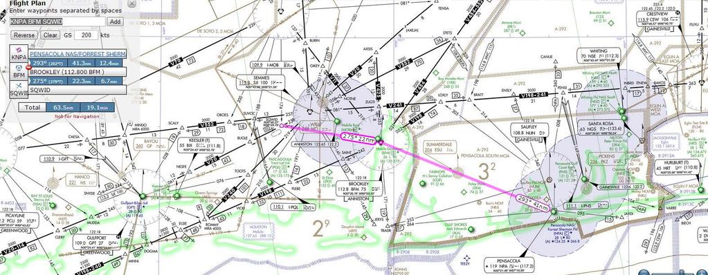
1 I3101 WORKSHEET Planned Route: Takeoff: KNPA, RWY 25R Altitude: 6000 Route: Radar departure from KNPA BFM (VOR holding) SQWID Approaches: KMOB VOR-A (arcing approach), KMOB RVFAC ILS RWY 15 KMOB RVFAC LOC RWY 15 Prerequisites: -IN1203-4, IN1206-7, IN , and IN (Instruments CAI) -Q4390 (NATOPS check-ride) Syllabus Notes: -IUT shall meet or exceed these approach-type requirements. A minimum of six approaches are required for this block. GCA 1 (PAR or ASR) ILS 1 LOC 1 VOR 2 Special Syllabus Requirements: -None Discuss Items a. UFCP DME HOLD function b. FMS setup Flight plan and approaches may be loaded for training however flight should be conducted PFD Source to VOR/LOC c. Scan Patterns FTI information d. Any emergency procedure 1
2 CNATRAINST B IUT T-6B RADIO INSTRUMENTS I3100 BLOCK IUT GRADE SHEET DATE INSTRUCTOR MEDIA: OFT/UTD VT- BRIEF TIME: NAME: EVENT: CTS MANEUVER REF MIF I3101 I GENERAL KNOWLEDGE / PROCEDURES 3+ X X 2 EMERGENCY PROCEDURES 3+ X X 3 HEADWORK / SITUATIONAL AWARENESS 3+ X X 4 BASIC AIRWORK 4+ X X 5 IN-FLIGHT CHECKS / FUEL MANAGEMENT 3+ X X 6 IN-FLIGHT PLANNING / 4+ X X AREA ORIENTATION 7 TASK MANAGEMENT 3+ X X 8 COMMUNICATION 4+ X X 9 MISSION PLANNING / BRIEFING / 3+ X X DEBRIEFING 10 GROUND OPERATIONS 4 11 TAKEOFF 4+ X X 12 DEPARTURE 4+ X X 13 INSTRUCTIONAL SKILLS / STUNDENT 3+ X X MANAGEMENT 41 STEEP TURNS 4+ X 42 IFR UNUSUAL ATTITUDES 4+ X 43 POINT-TO-POINT 3+ X 44 HOLDING 4+ X 45 ENROUTE PROCEDURES 4+ X X 46 ENROUTE DESCENT 4+ X X 47 HIGH-ALTITUDE APPROACH 3 48 TEARDROP APPROACH 4 49 ARCING APPROACH 4 X 50 HILO APPROACH 4 X 51 PROCEDURE TURN APPROACH 4 52 RVFAC APPROACH 4 X X 53 GPS APPROACH 4 54 PAR APPROACH 4 X 55 ASR APPROACH 4 X 56 VOR FINAL 3+ X X 57 ILS FINAL 3+ X 58 LOC FINAL 3+ X 59 GPS FINAL 3 60 BACKUP FLIGHT INSTRUMENT APPROACH 3 61 CIRCLING APPROACH 3 62 MISSED APPROACH 4 63 TRANSITION TO LANDING / LANDING 4+ X X Syllabus Notes: a. I3101 shall be conducted in the OFT. I3102 should be conducted in the OFT, but it may be conducted in the UTD. b. IUTs shall meet or exceed the following approach-type requirements: 1 GCA (PAR or ASR),1 ILS,1 LOC, 2 VOR A minimum of six approaches are required for this block. Discuss 13101: UFCP, FMS Setup, Scan Patterns I3102: Battery Failure, Generator Failure, Backup Flight Instrument B Rev 03/16/2017
3
4 15 R GCV Chan 104 MOBILE, ALABAMA VORTAC SJI Rwy Idg APP CRS TDZE 104 Chan 100 Apt Elev N/A N/A 219 AL-267 (FAA) VOR or TACAN-A MOBILE RGNL(MOB) T ASR MISSED APPROACH: Climb to 900, then climbing right turn to 2000 on heading 200 and SJI R-140 to SAINT INT/BFM 9.2 DME and hold. ATIS MOBILE APP CON MOBILE TOWER GND CON (CTAF) L CLNC DEL UNICOM MSA S J I25 NM 3100 R-284 (IF) TACCU SJI 7 IAF SEMMES SJI Chan 100 SE-4, 17 AUG 2017 to 14 SEP SJI Arc 1800 No P T (7) (IAF) SQWID SJI 7 R UBACE 321 SJI R BROOKLEY BFM Chan 75 R-242 SE-4, 17 AUG 2017 to 14 SEP 2017 ELEV SAINT BFM 9.2 P A from FAF TWR NM 8502 X 150 H H P 4376 X H 36 x 283 x A Remain within 10 NM SJI VORTAC hdg 200 SJI R-140 UBACE SJI 5.6 SAINT MIRL Rwy HIRL Rwy FAF to MAP 5.6 NM Knots Min:Sec 5:36 3:44 2:48 2:14 1:52 MOBILE, ALABAMA Amdt 2A 29MAY14 CATEGORY A B C D C CIRCLING (500-1) 30 41'N-88 15'W 5.6 NM ( ) (600-2) MOBILE RGNL(MOB) VOR or TACAN-A
5 GCV Chan 104 R-174 R-174 MOBILE, ALABAMA LOC I-MOB Rwy Idg 8502 APP CRS TDZE Apt Elev 219 AL-267 (FAA) ILS or LOC RWY 15 MOBILE RGNL(MOB) T ** RVR 1800 authorized with use of FD or AP or HUD to DA. MALSR A For inop MALSR increase S-ILS 15 Cat E visibility to RVR A 3 5 ASR 4000 and S-LOC 15 Cats C/D/E visibility to 1 8 mile. MISSED APPROACH: Climb to 900 then climbing right turn to 2000 on heading 200 and SJI VORTAC R-140 to SAINT INT/BFM 9.2 DME and hold. ATIS MOBILE APP CON MOBILE TOWER GND CON CLNC DEL UNICOM (CTAF) L Cat E Procedure Turn NA - RADAR REQUIRED BFM R-301 (CFLSL) x (IAF) 145 CAYAT INT RADAR R-042 SE-4, 17 AUG 2017 to 14 SEP 2017 SQWID GPT 34.8 GPT109 Chan 27 ALTERNATE MISSED APCH FIX GCV Chan R to CAYAT 042 (3.6) R-061 GPT109 Chan 27 SQWID GPT 34.8 SEMMES SJI Chan R SAINT BFM LOCALIZER I-MOB R-242 ELEV to CAYAT 301 (16) NM from FAF BROOKLEY BFM Chan 75 MSA S JI 25 NM TDZE 215 SE-4, 17 AUG 2017 to 14 SEP 2017 Remain within 10 NM GS 3.00 TCH VGSI and ILS glidepath not coincident (VGSI Angle 3.00/TCH 50). CATEGORY S-ILS 15** S-LOC 15 C CIRCLING MOBILE, ALABAMA Amdt 31A 29MAY14 A (500-1) CAYAT INT RADAR NM hdg 200 B C D E 415/ (200-2 ) 1 700/ (500-2 ) 700/ (500-1) ( ) 561 (600-2) 30 41'N-88 15'W SJI R-140 SAINT NA 15 A 5 Knots P TWR 348 HIRL Rwy X 150 H MIRL Rwy P X 150 A 5 FAF to MAP 4.8 NM x 283 x Min:Sec 4:48 3:12 2:24 1:55 1:36 MOBILE RGNL(MOB) ILS or LOC RWY 15 H H
6 ILS NAVAID Setup - D LIDS D LIDS is a useful acronym to help set up for the ILS approach. DME Hold (as required) Localizer Set ( Set frequency in UFCP ) Inbound course (set FAC in the CDI ) Display (set PFD NAV source for LOC) Speed Some examples: Radar downwind Straight-in - cruise speed until 5 nm from FAF Procedure track until 5 NM from FAF Procedure Turn until 5 NM from FAF

7 ILS NAVAID Setup - D LIDS Lets look at the ILS RWY 13R at KNGP. Prior to turning off the ARC onto the Final Approach course or while being vectored to final D LIDS would be need to be accomplished. DME Hold From the approach plate we can see that the DME for the approach is NOT from the Localizer I-NGP but from the TRUAX VORTAC NGP would be entered into the UFCP via W3 on the UFCP s persistent display page. Once a VHF NAV frequency is loaded, it s associated DME can be locked IN using the DME HOLD function.
8 ILS NAVAID Setup - D LIDS On the UFCP press the NAV TUNE button until the DME page is displayed along with the NAVAID frequency you wish to HOLD
 following the frequency.")
9 ILS NAVAID Setup - D LIDS On the UFCP press the NAV TUNE button until the DME page is displayed along with the NAVAID frequency you wish to HOLD Press the W2 button to activate the DME Hold function. This will be indicated by an (H) following the frequency. (The (H) can be toggled on/off using the W2 button) Once set, the DME will remain referenced from this NAVAID until the (H) is removed.

10 ILS NAVAID Setup - D LIDS Localizer Set Using the UFCP return to the persistent display page and load the Localizer frequency I-NGP into W3. Inbound Course Set the FAC into the CDI
11 ILS NAVAID Setup - D LIDS DISPLAY Ensure that PFD Source is set to LOC
12 ILS NAVAID Setup - D LIDS DISPLAY Ensure that PFD Source is set to LOC On the PFD note the Localizer frequency I-NGP shown below the PFD SOURCE
13 ILS NAVAID Setup - D LIDS DISPLAY Ensure that PFD Source is set to LOC On the PFD note the Localizer frequency shown below the PFD SOURCE Below the Localizer frequency the Distance in NM and the DME hold NAVAID (NGP 114.0) appear in amber colored type. SPEED Maintain the speed appropriate for your position along the approach.
14 CHAPTER TWO PRIMARY INSTRUMENT NAVIGATION T-6B 204. SCAN PATTERNS Once PAT is accomplished, SCAN to maintain the desired performance. Scan is the systematic process of monitoring the crosscheck/performance instruments to detect deviation from desired flight parameters (error detection), then applying the proper controls to make an appropriate timely correction. The goal is: Early Error Detection and Correction! In any scan method there are two basic groups of instruments: Power/Control Instruments: The four basic inputs that the pilot can make in the aircraft are: 1. PITCH 2. ROLL 3. POWER 4. YAW Initial Power and Attitude inputs are made referencing the Power/Control Instruments: 1. ADI 2. TORQUE Crosscheck/Performance Instruments: These instruments are used to detect deviations from required performance and inform you of the inputs required to regain the desired flight parameters. 1. ALTIMETER 2. VSI 3. AIRSPEED 4. ANGLE OF BANK (ROLL POINTER) 5. TURN NEEDLE 6. HSI 2-2 FUNDAMENTAL INAV CONCEPTS
15 CHAPTER TWO PRIMARY INSTRUMENT NAVIGATION T-6B 7. SIDESLIP INDICATOR An active scan will let you know which control needs adjusted, the direction it needs to be moved, and a sense of how much it should be moved. HUB and SPOKE Method: The Hub is the Attitude Gyro (ADI). The Spokes are the crosscheck/performance instruments. A basic instrument scan sequence consists of: GYRO - Set required Attitude for desired performance NOSE - Crosscheck nose instrument(s) GYRO - Adjust Pitch to keep or return to desired parameters WING - Crosscheck wing performance instrument(s) GYRO - Adjust Roll to keep or return to desired parameters PERFORMANCE/PROGRESS - Crosscheck aircraft performance/maneuver progress GYRO - Stabilize attitude ADDITIONAL - Fine tune the rudder for Yaw (sideslip) and Power for needed changes in torque NOTE Approximately 50% of the time the pilot should be looking at the ADI. This will aid in preventing unintended inputs while insuring desired inputs are appropriate and controlled. ADI is big picture, crosscheck/performance instruments are for fine tuning. The crosscheck/performance instruments for Pitch, Roll, and Power depend upon the maneuver being conducted. The crosscheck for Yaw is always the sideslip indicator. The following table outlines the different flight maneuvers you will encounter in this stage of training and the appropriate crosscheck/performance instruments. FUNDAMENTAL INAV CONCEPTS 2-3
16 CHAPTER TWO PRIMARY INSTRUMENT NAVIGATION T-6B MANEUVER STRAIGHT AND LEVEL CONSTANT ANGLE OF BANK TURNS CONSTANT AIRSPEED CLIMBS & DESCENTS CONSTANT RATE TURNS CONSTANT RATE CLIMBS & DESCENTS CLIMBING OR DESCENDING TURN AT CONSTANT ANGLE OF BANK & AISPEED NOSE CROSSCHECK ALTIMETER, VSI ALTIMETER, VSI WING CROSSCHECK PERFORMANCE/ PROGRESS INSTRUMENT ADDITIONAL INSTRUMENTS HSI AIRSPEED SIDESLIP, TORQUE AOB HSI AIRSPEED SIDESLIP, TORQUE AIRSPEED HSI ALTIMETER SIDESLIP, TORQUE ALTIMETER, VSI AIRSPEED AIRSPEED TURN NEEDLE AOB HSI AOB HSI CLOCK AIRSPEED ALTIMETER VSI CLOCK HSI AIRSPEED SIDESLIP, TORQUE SIDESLIP, TORQUE SIDESLIP, TORQUE 205. SPATIAL DISORIENTATION Figure 2-1 Crosscheck/Performance Instruments Spatial disorientation can be defined simply as a body sensation which tells the aviator that his aircraft is in a particular attitude, when the aircraft is actually in an entirely different position relative to the horizon. This false sensation is derived from a number of sources: the inner ear and vestibular stimulation are the most common. Spatial disorientation usually does not occur when a pilot has visual reference to the horizon, or at least, the pilot pays little attention to his body feelings, since his sight simply overcomes them. Disorientation occurs when there is no reference to the horizon; however, this does not necessarily limit vertigo to flying in the clouds. It can occur when the aircraft is flying in visual meteorological conditions (VMC), on a day when there are large buildups, when flying above a layer of clouds, when flying in and out of a broken layer, or when launching at night with no clear horizon. Vertigo or the disorientation sensation is, and always will be, a factor in aviation, but is dangerous only when the pilot believes and flies his senses instead of the reliable instruments. The spatial disorientation training in the T-6B will demonstrate and emphasize three specific facts: 1. A pilot s attitude sensations are generally unreliable. 2. The pilot cannot recover to straight and level flight using these sensations. 3. Instruments are the only way to recognize and recover from unusual attitudes in Instrument Meteorological Conditions (IMC). 2-4 FUNDAMENTAL INAV CONCEPTS
This page is intentionally blank. GARMIN G1000 SYNTHETIC VISION AND PATHWAYS OPTION Rev 1 Page 2 of 27
 This page is intentionally blank. 190-00492-15 Rev 1 Page 2 of 27 Revision Number Page Number(s) LOG OF REVISIONS Description FAA Approved Date of Approval 1 All Initial Release See Page 1 See Page 1 190-00492-15
Fokker 50 - Automatic Flight Control System
 GENERAL The Automatic Flight Control System (AFCS) controls the aircraft around the pitch, roll, and yaw axes. The system consists of: Two Flight Directors (FD). Autopilot (AP). Flight Augmentation System
Table of Contents. Introduction 3. Pictorials of the 40 and 50 Systems 4. List of Applicable Acronyms 6
 Table of Contents Introduction 3 Pictorials of the 40 and 50 Systems 4 List of Applicable Acronyms 6 System 40 Modes of Operation 7 System 40 Functional Preflight Procedures 10 System 40 In Flight Procedures
Integrated Cockpit Display System ICDS 1000 Pilot Operation Handbook
 Integrated Cockpit Display System ICDS 1000 Pilot Operation Handbook ICDS1000 Pilot Operating Handbook Revision 1.3 572-0540 page 1 Table Of Contents Electronic Attitude Direction Indicator (EADI)... 8
NDB Approach Background
 NDB Approaches 1 NDB Approach Background One of the oldest and most disliked approaches Can use NDBs both on and off of the destination airport NDB approaches can be on the TO or FROM side of an NDB; some
Dash8-200/300 - Automatic Flight AUTOMATIC FLIGHT CONTROLS AND INDICATORS. Page 1
 AUTOMATIC FLIGHT CONTROLS AND INDICATORS FLIGHT GUIDANCE MODE SELECTORS (alternate action) - Engages flight director modes of operation. - Flight director command bars display lateral and/or vertical guidance
Instrument Flight Procedures - Glass Cockpits
 Instrument Flight Procedures - Glass Cockpits The concepts contained here are general in nature and can be used by all however, they are targeted toward glass cockpits and, more specifically, integrated
GRT Autopilot User Guide. All GRT EFIS Systems
 All GRT EFIS Systems Revision A 22-May-2014 Copyright 2014 3133 Madison Ave. SE Wyoming, MI 49548 (616) 245-7700 www.grtavionics.com Revision Notes Revision Date Change Description A 22-May-2014 Complete
NAVIGATION INSTRUMENTS - BASICS
 NAVIGATION INSTRUMENTS - BASICS 1. Introduction Several radio-navigation instruments equip the different airplanes available in our flight simulators software. The type of instrument that can be found
SA4550. Pilot s Guide Effectivity and Errata
 SA4550 Pilot s Guide Effectivity and Errata Insert this update ahead of the cover page of the above referenced Pilot s Guide. The environmental categories in the Technical Specifications contained in Section
FlyRealHUDs Very Brief Helo User s Manual
 FlyRealHUDs Very Brief Helo User s Manual 1 1.0 Welcome! Congratulations. You are about to become one of the elite pilots who have mastered the fine art of flying the most advanced piece of avionics in
RJNK / KOMATSU AD CHART KOMATSU AD. AIP Japan KOMATSU RJNK-AD TWY C1 THRU C5. Installed on. Example for MANDATORY
 AIP Japan RJNK-AD2-24.1 RJNK / AD CHART AD TRUE NORTH APRON FLOOD LGT VORTAC () PAPI Angle 2.5 MEHT 20.0m(66ft) 570.86m CENTER-HELIPAD TAXIING GUIDANCE SIGNS 1 2 3 4 5 6 7 8 C-4 C-3 C-2 C-1 EAST-HELIPAD
MILITARY AERONAUTICAL INFORMATION PUBLICATION (M.A.I.P.) LOW ALTITUDE BALKANS THEATER - FALCON BMS 4.33
 LOW ALTITUDE BALKANS THEATER - FALCON BMS 4.33") MILITARY AERONAUTICAL INFORMATION PUBLICATION (M.A.I.P.) LOW ALTITUDE AIRPORT DIAGRAMS STANDARD INSTRUMENT DEPARTURES (SID) INSTRUMENT APPROACH PROCEDURES (IAP) BALKANS THEATER - FALCON BMS 4.33 Created
MILITARY AERONAUTICAL INFORMATION PUBLICATION (M.A.I.P.) LOW ALTITUDE AIRPORT DIAGRAMS STANDARD INSTRUMENT DEPARTURES (SID) INSTRUMENT APPROACH PROCEDURES (IAP) BALKANS THEATER - FALCON BMS 4.33 Created
491229N W DME I-DD. Freq-paired. Anemometer PAPI (3 ) MEHT 55. Fire Station. Hold. Twy E. Hold E Hold C2. Twy A (40) (62) Terminal Building
 MEHT 55. Fire Station. Hold. Twy E. Hold E Hold C2. Twy A (40) (62) Terminal Building") AERODROME CHART - ICAO ELEVATIONS IN FEET AMSL... HEIGHTS IN FEET ABOVE AD... (121) 491229N 0021144W 002 1230W 002 1200W 002 1130W ELEV 002 1100W (1 Sep 05) AD 2--2-1 491300N N 491300N 491230N 09 Displaced
AERODROME CHART - ICAO ELEVATIONS IN FEET AMSL... HEIGHTS IN FEET ABOVE AD... (121) 491229N 0021144W 002 1230W 002 1200W 002 1130W ELEV 002 1100W (1 Sep 05) AD 2--2-1 491300N N 491300N 491230N 09 Displaced
Dash8 - Q400 - Autoflight
 12.3.1 Introduction The Automatic Flight Control System (AFCS), provides fail-safe operation of flight director guidance, autopilot, yaw damper and automatic pitch trim functions. 12.3.2 General The Automatic
FAA APPROVED AIRPLANE FLIGHT MANUAL SUPPLEMENT FOR. Trio Pro Pilot Autopilot
 Page 1 480 Ruddiman Drive TRIO AP Flight Manual Supplement North Muskegon, MI 49445 L-1006-01 Rev D FOR Trio Pro Pilot Autopilot ON Cessna 172, 175, 177, 180, 182, 185 and Piper PA28 Aircraft Document
Page Chg
 Page Chg Cover...0 Page #...1 TOC-1...1 TOC-2..1 1-1.1 1-2.1 1-3.1 1-4...0 1-5...1 1-6. 1 1-7. 1 1-8. 1 1-9. 1 1-10...1 1-11..1 1-12..1 1-13..1 1-14..1 2-1.0 2-2.0 2-3.1 Page Chg 2-4.0 3-1.0 3-2.0 3-3.0
Head-Up Guidance System. HGS Pilot Guide for the Bombardier CRJ 700
 Head-Up Guidance System HGS Pilot Guide for the Bombardier CRJ 700 Registration Notice HGS is a registered trademark of Rockwell Collins Flight Dynamics Proprietary Notice The information contained in
FOUND FBA-2C1/2C2 BUSH HAWK EQUIPPED WITH SINGLE GARMIN GNS-430 # 1 VHF-AM COMM / VOR-ILS / GPS RECEIVER
 FOUND SUPPLEMENT M400-S11 Transport Canada Approved Flight Manual Supplement For FOUND BUSH HAWK EQUIPPED WITH SINGLE # 1 VHF-AM COMM / VOR-ILS / GPS RECEIVER Section 1 General is Unapproved and provided
AUTOMATIC FLIGHT CONTROL SYSTEM
 TRIDEN AUTOMATIC FLIGHT CONTROL SYSTEM PILOT S OPERATING HANDBOOK 68S1135 Rev B 02-05-03 FACTORY SERVICE CENTERS Century Flight Systems, Inc. has established Factory owned and operated Customer Service
EMBRAER 135/145 Autopilot
 EMBRAER 135/145 Autopilot GENERAL The Primus 1000 (P-1000) Automatic Flight Control System (AFCS) is a fully integrated, fail passive three-axis flight control system which incorporates lateral and vertical
Operating Handbook. For. Gemini Autopilot
 Operating Handbook For Gemini Autopilot TRUTRAK FLIGHT SYSTEMS 1488 S. Old Missouri Road Springdale, AR 72764 Ph. 479-751-0250 Fax 479-751-3397 www.trutrakap.com Table of Contents 1. Revisions... 5 2.
SECTION 2-19 AUTOPILOT
 AIRPLANE SECTION 2-19 Block General...2-19-05...01 Automatic Flight Control System...2-19-05...02 Flight Guidance System...2-19-05...04 Flight Director...2-19-05...04 Autopilot...2-19-05...04 Flight Director
DME I-GH & I-UY Freq-paired NDB GUY 361 ILS LLZ I-GH ILS LLZ I-UY PAPI (3 ) MEHT m x 45m Asphalt. TwyB Hold PAPI (3 ) MEHT 47
 MEHT m x 45m Asphalt. TwyB Hold PAPI (3 ) MEHT 47") AERODROME CHART - ICAO 002 3700W ELEVATIONS IN FEET AMSL... HEIGHTS IN FEET ABOVE AD... (51) 002 3630W 002 0W 002 3530W (12 May 05) AD 2--2-1 492606N 0027W ELEV 387 N 492630N 492630N 320 330 ILS LLZ I-GH
AERODROME CHART - ICAO 002 3700W ELEVATIONS IN FEET AMSL... HEIGHTS IN FEET ABOVE AD... (51) 002 3630W 002 0W 002 3530W (12 May 05) AD 2--2-1 492606N 0027W ELEV 387 N 492630N 492630N 320 330 ILS LLZ I-GH
SAARBRÜCKEN Germany (EDDR)
") Hangars 1 2 For flight simulator use only. Not to be used for real world flight. 27 Germany () 27 Area of competency apron control Area of competency DFS TWR Terminal B 09 Noise abetement facility for
Hangars 1 2 For flight simulator use only. Not to be used for real world flight. 27 Germany () 27 Area of competency apron control Area of competency DFS TWR Terminal B 09 Noise abetement facility for
STC FLIGHT FUNCTIONAL TEST
 GDC31 Roll Steering Converter 1049-2080-02 REV A 2004, DAC International All Rights Reserved. 6702 McNeil Drive Austin, Texas 78729 (512) 331-5323 Phone (512) 331-4516 Fax Page 1 of 14 Record of Revisions
HAZARD AVOIDANCE. Displaying traffic on the Navigation Map. Displaying traffic information (PFD Inset Map):
:") HAZARD AVOIDANCE Displaying traffic on the Navigation Map 1) Ensure that the TAS system is operating. With the Navigation Map displayed, select the MAP Softkey. 2) Select the TRAFFIC Softkey. Traffic is
HAZARD AVOIDANCE Displaying traffic on the Navigation Map 1) Ensure that the TAS system is operating. With the Navigation Map displayed, select the MAP Softkey. 2) Select the TRAFFIC Softkey. Traffic is
Understanding Spatial Disorientation and Vertigo. Dan Masys, MD EAA Chapter 162
 Understanding Spatial Disorientation and Vertigo Dan Masys, MD EAA Chapter 162 Topics Why this is important A little aviation history How the human body maintains balance and positional awareness Types
Chapter 10 Navigation
 Chapter 10 Navigation Table of Contents VHF Omnidirectional Range (VOR) VOR Orientation Course Determination VOR Airways VOR Receiver Check Points Automatic Direction Finder (ADF) Global Positioning System
SD3-60 AIRCRAFT MAINTENANCE MANUAL
 AMM 24.0.0.0FLIGHT DIRECTOR SYSTEM - DESCRIPTION & OPERATION 1. Description A. General Refer to Figure 1. Identical, left and right, systems are installed (one for each pilot); each provides information
RJOM / MATSUYAMA AD CHART MATSUYAMA AP N M. AIP Japan MATSUYAMA RJOM-AD WIND DIRECTION INDICATOR LGT RWY 32 OVERRUN LGT APCH LGT BEACONS. 461.
 AIP Japan RJOM-AD2-24.1 RJOM / AD CHART AP 340m TWR 405m T S R Q P N M J K G H E F C D A B 8 9 10 11 12 13 ABN OVERRUN LGT PAPI Angle 3.0 MEHT 20m (66 ft) 190m WIND DIRECTION INDICATOR LGT 85m 1 2 3 5
Page Chg
 Page Chg Cover...0 Page #...2 TOC-1...2 TOC-2..2 1-1 2 1-2.2 1-3.2 1-4...2 1-5...2 1-6. 2 1-7. 2 1-8. 2 1-9. 2 1-10...2 1-11..2 1-12..2 1-13..2 1-14..2 1-15..2 1-16..2 1-17..2 1-18...2 2-1.0 2-2.0 2-3.2
P/N 135A FAA Approved: 7/26/2005 Section 9 Initial Release Page 1 of 10
 FAA APPROVED AIRPLANE FLIGHT MANUAL SUPPLEMENT FOR GARMIN GNS 430 - VHF COMM/NAV/GPS Serial No: Registration No: When installing the Garmin GNS 430 - VHF COMM/NAV/GPS in the Liberty Aerospace XL2, this
ILS or LOC RWY 32. ILS or LOC RWY 32. RNAV 1-GPS or RADAR REQUIRED. NC-1, 01 FEB 2018 to 01 MAR NC-1, 01 FEB 2018 to 01 MAR
 RI CIY, SOU KO LOC/ME I-R 09. Chan0 CRS Rwy Idg 870 ZE 60 pt Elev 204 ME and RV -GS required. ILS glideslope unusable for MLSR coupled approaches below 60. For inop LS, increase S-ILS Cat E visibility
Japan-US Aviation Environmental Workshop Fukutake Hall University of Tokyo 29 November 2017
 Japan-US Aviation Environmental Workshop Fukutake Hall University of Tokyo 29 November 2017 Keiichi Tamura All Nippon Airways B787 Technical Pilot, Dr. Eng. 2 Fundamentals of PBN (RNAV / RNP) Fundamentals
PERFORM A DME ARC. This document illustrates how to perform a DME arc with a HSI-equipped Beechcraft 90. Descent steps
 PERFORM A DME ARC 1. Introduction This document illustrates how to perform a DME arc with a HSI-equipped Beechcraft 90. 2. Preparatory work 2.1. Scenario You will need to open the following charts of Clermont
APPENDIX C VISUAL AND NAVIGATIONAL AIDS
 VISUAL AND NAVIGATIONAL AIDS APPENDIX C VISUAL AND NAVIGATIONAL AIDS An integral part of the airport system is the visual and navigational aids provided to assist pilots in navigating both on the airfield
VOR/DME APPROACH WITH A320
 1. Introduction VOR/DME APPROACH WITH A320 This documentation presents an example of a VOR/DME approach performed with an Airbus 320 at LFRS runway 21. This type of approach is a non-precision approach
Operating Handbook. For. Gemini Autopilot
 Operating Handbook For Gemini Autopilot TRUTRAK FLIGHT SYSTEMS 1488 S. Old Missouri Road Springdale, AR 72764 Ph. 479-751-0250 Fax 479-751-3397 www.trutrakap.com Table of Contents 1. Revisions... 5 2.
ELITE Operator s Manual
 ELITE Jet v8 ELITE Operator s Manual The aircraft simulated by ELITE Jet represents the well known civil airliner MD-81. The instrumentation of the cockpit represents all standard instruments. Only the
not authorized for IFR use. authorized for IFR use under VMC. authorized for IFR use under IMC until the runway is in sight.
 Gleim FAA Test Prep: Instrument Pilot (20 questions) Name: Date: Circle the correct answer on the question sheets AND fill in the corresponding circle on the separate answer sheet. [1] Gleim #: 3.4.32
Understanding VOR's, VORTAC's and How To Use Them
 Understanding VOR's, VORTAC's and How To Use Them by Hal Stoen Used by California Airlines (CAX) with permission from Hal Stoen 1998 first release: 2 December, 1998 INTRODUCTION The practical aspects of
ILS REFERENCE DATUM 53 DGC IFF 0.8DME. FIELD ELEV 30ft TDZ ELEV 32ft STA TO RWY 34. PALS OUT RVR 1400m VIS 1400m PALS AVBL. RVR 1200m VIS 1200m
 FUKUOKA ILS RWY 34 FUKUOKA APP ILS-LLZ FUKUOKA TOWER RADAR AVAILABLE 1191-11965 - 1207 1089 IFF ILS-GP 3293 1184-1262 2612-2708 ILS-DME 987(CH-26X) 2368 ATIS 1272 377 VER6 45 W 2003 253 073 IKE MHA 4000
Page Chg
 Page Chg Cover...0 Page #...4 TOC-1...3 TOC-2..3 1-1 2 1-2.3 1-3.3 1-4...3 1-5...3 1-6. 3 1-7. 3 1-8. 4 1-9. 4 1-10...3 1-11..4 1-12..4 1-13..3 1-14..3 1-15..3 1-16..3 1-17..3 1-18...3 1-19..3 2-1.0 2-2.0
EMERGENCY AND ABNORMAL PROCEDURES...
 TABLE OF CONTENTS 1 GENERAL...5 1.1 SYSTEM OVERVIEW...5 2 LIMITATIONS...6 2.1 SOFTWARE VERSIONS...6 2.2 AIRSPEED LIMITATION...6 2.3 WEIGHT & CENTER OF GRAVITY...6 2.4 RSM GPS USAGE...6 2.5 GEOGRAPHIC LIMITATION...6
Page Chg
 Page Chg Cover...0 Page #...1 TOC-1...1 TOC-2...1 1-1.1 1-2.0 1-3.1 1-4...1 1-5...1 1-6. 1 1-7. 1 1-8. 1 1-9. 1 1-10...1 1-11..1 1-12..1 1-13..2 1-14..1 1-15..1 1-16..1 1-17..1 1-18..1 2-1.0 2-2.0 Page
MOONEY AIRCRAFT CORPORATION P. 0. Box 72 Kerrville, Texas FAA APPROVED
 P. 0. Box 72 Kerrville, Texas 78029 FAA APPROVED AIRPLANE FLIGHT MANUAL SUPPLEMENT FOR MOONEY M20J, M20K, M20L, M20M, M20R with Aircraft Serial No. Aircraft Reg. No. This supplement must be attached to
Navigation Systems. Chapter 7. Introduction. Ground Wave. Basic Radio Principles
 Chapter 7 Navigation Systems Introduction This chapter provides the basic radio principles applicable to navigation equipment, as well as an operational knowledge of how to use these systems in instrument
VT-27 Formation Script
 1 VT-27 Formation Script Cockpit Checklist (BOTH) o Input briefed VHF Tactical Frequency (123.47, 123.57, or 123.67) (BOTH) LEAD: -Tac Call Sign- One is ready to close canopy on VHF Tactical Frequency
AIRCRAFT AVIONIC SYSTEMS
 AIRCRAFT AVIONIC SYSTEMS B-777 cockpit Package C:\Documents and ettings\administrato Course Outline Radio wave propagation Aircraft Navigation Systems - Very High Omni-range (VOR) system - Instrument Landing
MINIMUM EQUIPMENT LIST OPERATIONAL PROCEDURES ATA 34 NAVIGATION F100 ATA 34/ NAVIGATION CAA-01 ATA 34
 1 of 12 ATA 34/ NAVIGATION 2 of 12 11-1 Static ports Dispatch with ports at one side inoperative Take-off: With the static ports capped at one side, compensation for slip and crosswind conditions (take-off
Operating Handbook For FD PILOT SERIES AUTOPILOTS
 Operating Handbook For FD PILOT SERIES AUTOPILOTS TRUTRAK FLIGHT SYSTEMS 1500 S. Old Missouri Road Springdale, AR 72764 Ph. 479-751-0250 Fax 479-751-3397 Toll Free: 866-TRUTRAK 866-(878-8725) www.trutrakap.com
2 Flight Plans 1 Fill in the appropriate boxes 2 Find acceptable routes 3 Useful Newbie Comments
 VATSIM Requirement 1 Download and install essential software 1 Your Sim MSFS, XPlane 2 Pilot Clients SB, FSInn 3 To find ATC Wazzaup, Servinfo, VATSpy, VATSIM Stats, Pilot Client 4 Interpreting This Requirement
11 Traffic-alert and Collision Avoidance System (TCAS)
") 11 Traffic-alert and Collision Avoidance System (TCAS) INSTRUMENTATION 11.1 Introduction In the early nineties the American FAA stated that civil aircraft flying in US airspace were equipped with a Traffic-alert
11 Traffic-alert and Collision Avoidance System (TCAS) INSTRUMENTATION 11.1 Introduction In the early nineties the American FAA stated that civil aircraft flying in US airspace were equipped with a Traffic-alert
KAP 140 Two Axis with Altitude Preselect Operation
 Two Axis/Altitude reselect Operations K 0 Two Axis with Altitude reselect Operation The K 0 is a digital, panel-mounted autopilot system for light aircraft. 7 8 K 0 D AV V AT D Two-axis w/altitude reelect
SkyView. Autopilot In-Flight Tuning Guide. This product is not approved for installation in type certificated aircraft
 SkyView Autopilot In-Flight Tuning Guide This product is not approved for installation in type certificated aircraft Document 102064-000, Revision B For use with firmware version 10.0 March, 2014 Copyright
Digiflight II SERIES AUTOPILOTS
 Operating Handbook For Digiflight II SERIES AUTOPILOTS TRUTRAK FLIGHT SYSTEMS 1500 S. Old Missouri Road Springdale, AR 72764 Ph. 479-751-0250 Fax 479-751-3397 Toll Free: 866-TRUTRAK 866-(878-8725) www.trutrakap.com
Caution : When take off RWY10, high terrain exists in southeast side of airport (Right of departure course).
.") RJNG-AD2-24.1 RJNG / SID NORIC TWO DEPARTURE RWY28 : Climb via GFT R-285 to GFT 6DME, then turn right,... RWY10 : Turn left, climb via GFT R-090 to GFT 7DME, then turn left,......climb via GFT R-044 to
RJNG-AD2-24.1 RJNG / SID NORIC TWO DEPARTURE RWY28 : Climb via GFT R-285 to GFT 6DME, then turn right,... RWY10 : Turn left, climb via GFT R-090 to GFT 7DME, then turn left,......climb via GFT R-044 to
Operations Manual. Caution: Preliminary
 Operations Manual Caution: Preliminary This manual is incomplete at this time. Most, but not all of the data within the manual is accurate, although it is all subject to change and may not match the software
Apollo GPS Database Addendum
 Apollo GPS Database Addendum This document includes information that has been added to the waypoint database after the printing of the user s guide. A new waypoint type has been added to your database
Briefing the Approach
 Transcript Briefing the Approach Featuring: Doug Stewart Copyright PilotWorkshops.com, LLC. This material is available to members of the PilotWorkshops.com web site, which is the only place it can be legally
AUTOMATIC FLIGHT CONTROL SYSTEM TABLE OF CONTENTS CHAPTER 4
 TABLE OF CONTENTS CHAPTER 4 Page TABLE OF CONTENTS DESCRIPTION General Guidance Panel Autopilot System Autopilot Yaw Damper Autopilot Engage Autopilot Disengage PFD Annunciation Flight Director (FD) Flight
JeppView for Windows. General Information. Runway Information. Communication Information. jep=jeppesen
 Airport Information For VOGO Printed on 27 Jan 208 Page (c) SANERSON, INC., 208, ALL RIGHTS RESERVE jep= JeppView for Windows General Information Location: IN ICAO/IATA: VOGO / GOI Lat/Long: N5 22.85',
The Training Database is supplied as part of the RNS, and is loaded at the same time as the main program.
 THE TRAINING DATABASE The Training Database is supplied as part of the RNS, and is loaded at the same time as the main program. The Training Area is fictious, but the procedures are representative of the
HGS Model 5600 Pilot Guide
 Head-Up Guidance System HGS Model 5600 Pilot Guide Dual HGS Installation Embraer 170/190 Registration Notice HGS is a registered trademark of Rockwell Collins. Proprietary Notice The information contained
Airport Information. Details for ALEXANDROS PAPADIAMANDIS. State/Province
 Airport Information etails for ALEXANROS PAPAIAMANIS City SKIATHOS State/Province Country GRC Latitude N 39 0' 39.00" Longitude E 23 30' 3.00" Elevation 54 Longest Runway 5300 Magnetic Variance E 4.0 Fuel
CHAPTER NAVIGATION SYSTEMS
 18--00--1 NAVIGATION SYSTEMS Table of Contents REV 3, May 03/05 CHAPTER 18 --- NAVIGATION SYSTEMS Page TABLE OF CONTENTS 18-00 Table of Contents 18--00--1 INTRODUCTION 18-10 Introduction 18--10--1 FLIGHT
INSTRUCTOR REVIEW GUIDE LESSON N4SYS-17_IGR 1.5 HOURS AVIONICS SYSTEMS REVIEW
 Lecture Discussion 1 INSTRUCTOR REVIEW GUIDE LESSON N4SYS-17_IGR 1.5 HOURS AVIONICS SYSTEMS REVIEW Class Preparation Instructional Aids Aircrew Operating Handbook Volume 2.1 Aircraft Systems for the C-146A
Pilot s Guide KI 825. Bendix/King Safety Display System Electronic Horizontal Situation Indicator For Units Having -2, -3 and -4 Softwa re
 N Pilot s Guide KI 825 Bendix/King Safety Display System Electronic Horizontal Situation Indicator For Units Having -2, -3 and -4 Softwa re W A R N I N G The enclosed technical data is eligible for export
JEPPESEN 10-1R 30NM 20NM 10NM. Cochin 10NM 10NM COCHIN RADAR
 Printed from JeppView for Windows 5.3.. on 7 May 7; Terminal chart data cycle -7 (Expired); Notice: After 9 Feb 7, Z, this chart may no longer be valid VOI/OK INTL JAN 4 -R, INIA.RAAR.MINIMUM.ALTITUES.
Circle the correct answer on the question sheets and fill in the corresponding circle on the separate answer sheet.
 Gleim FAA Test Prep: Instrument Pilot (20 questions) IPGS Study Unit 3: Navigation Systems (IFH Ch 7, PHAK Ch 15) Name: Date: Circle the correct answer on the question sheets and fill in the corresponding
INSTALLATION MANUAL AND OPERATING INSTRUCTIONS
 INSTALLATION MANUAL AND OPERATING INSTRUCTIONS MD200-302/303/306/307 Series COURSE DEVIATION INDICATOR MID-CONTINENT INST. CO., INC MANUAL NUMBER 8017972 Revisions Rev. Date Description of Change ECO#
ENSTROM 480/480B OPERATOR S MANUAL AND FAA APPROVED ROTORCRAFT FLIGHT MANUAL SUPPLEMENT GARMIN GNS 430W/530W NAVIGATION SYSTEM
 ENSTROM 480/480B OPERATOR S MANUAL AND FAA APPROVED ROTORCRAFT FLIGHT MANUAL SUPPLEMENT GARMIN GNS 430W/530W NAVIGATION SYSTEM * * * * * REPORT NO. 28-AC-055 HELICOPTER SERIAL NO. HELICOPTER REGISTRATION
MGL Avionics. Odyssey/Voyager G2 and iefis
 MGL Avionics Odyssey/Voyager G2 and iefis Navigation This document applies to G2 version 1.1.0.1 or later, iefis 1.0.0.3 or later. Note: This document is based on the G2. The iefis system provides identical
The prior specification for navaid data was XP NAV810, which was compatible with X-Plane Changes in the spec for XP NAV1100 were:
 X-PLANE NAVIGATION DATA FOR NAVAIDS (USER_NAV.DAT & EARTH_NAV.DAT) FILE SPECIFICATION VERSION 1100 REVISION HISTORY 7 May 2009 Spec converted to this new format to support new web site (http://data.x-plane.com).
LOG OF REVISIONS Rev 1 RFMS, Eurocopter EC130 B4 G500H System. Page Date Number Description FAA Approved.
 Revision Number LOG OF REVISIONS Page Date Number Description FAA Approved 1 05/15/2014 All Complete Supplement See page 1 190-01527-16 Rev 1 RFMS, Eurocopter EC130 B4 G500H System Page 2 of 25 FAA APPROVED
MGL Avionics. iefis. Integrated Autopilot. User and installation manual. Manual dated 14 November Page 1
 MGL Avionics iefis Integrated Autopilot User and installation manual Manual dated 14 November 2014 Page 1 Table of Contents General...4 Autopilot abilities...4 External autopilot systems...4 Internal autopilot
Digiflight II SERIES AUTOPILOTS
 Operating Handbook For Digiflight II SERIES AUTOPILOTS TRUTRAK FLIGHT SYSTEMS 1500 S. Old Missouri Road Springdale, AR 72764 Ph. 479-751-0250 Fax 479-751-3397 Toll Free: 866-TRUTRAK 866-(878-8725) www.trutrakap.com
INSTALLATION MANUAL AND OPERATING INSTRUCTIONS
 INSTALLATION MANUAL AND OPERATING INSTRUCTIONS MD200-202/203/206/207 Series COURSE DEVIATION INDICATOR Mid-Continent Instruments and Avionics Manual Number 8017702 9400 E. 34 th Street N. Wichita, KS 67226
INSTALLATION MANUAL KI 208, KI 209 NAVIGATION INDICATORS
 RELEASED FOR THE EXCLUSIVE USE BY: AIRCRAFT ELECTRONICS ASSOCIATION h INSTALLATION MANUAL KI 208, KI 209 NAVIGATION INDICATORS MANUAL NUMBER 006-00140-0004 Revision 4, August 2002 RELEASED FOR THE EXCLUSIVE
CHANGE 1 CHAPTER FOUR - TACAN AND VOR NAVIGATION...
 CHANGE 1 CHAPTER FOUR - TACAN AND VOR NAVIGATION... 4-1 400. INTRODUCTION... 4-1 401. LESSON TOPIC LEARNING OBJECTIVES... 4-1 402. VOR - TACAN PROCEDURES AND OPERATING INSTRUCTIONS... 4-2 403. HOLDING...
G1000 Integrated Flight Deck. Cockpit Reference Guide for the Cessna Citation Mustang
 G1000 Integrated Flight Deck Cockpit Reference Guide for the Cessna Citation Mustang FLIGHT INSTRUMENTS NAV/COM/TRANSPONDER/AUDIO PANEL AUTOMATIC FLIGHT CONTROL SYSTEM GPS NAVIGATION FLIGHT PLANNING PROCEDURES
Alsim Simulation Operating Instructions
 Alsim Simulation Operating Instructions Overview of Simulation This Alsim simulation is primarily designed to familiarize you with the avionics in the Alsim MCC200 Flight Simulator. The avionics and autopilot
9.1 General. f-i TABLE OF CONTENTS SECTION 9 SUPPLEMENTS REPORT: VB-880
 TABLE OF CONTENTS Paragraph/ Supplement No. 9.1 General Page No. 9-1 I z J 4 5 6 AutoFIite II Autopilot Installation 9-3 AutoControl IIIB Autopilot Installation 9-5 Piper Electric Pitch Trim 9-9 Air Conditioning
Technology Considerations for Advanced Formation Flight Systems
 Technology Considerations for Advanced Formation Flight Systems Prof. R. John Hansman MIT International Center for Air Transportation How Can Technologies Impact System Concept Need (Technology Pull) Technologies
NAVIGATION AND PITOT-STATIC SYSTEMS
 NAVIGATION AND PITOT-STATIC SYSTEMS. GENERAL This chapter describes the navigation systems, units, and components which provide airplane navigational information. Included are pitot-static, gyros, compass,
Models HX, HS & WS. User s Guide and Reference
 GRT HORIZON Models HX, HS & WS User s Guide and Reference September 2015 Grand Rapids Technologies, Inc. 3133 Madison Avenue SE Wyoming MI 49548 616-245-7700 www.grtavionics.com INTENTIONALLY BLANK GRT
MKN LGMK/JMK PIDAX 1A [PIDA1A] RWY 34 ARRIVALS VARIX 1Q HOLDING OVER MKN 263^ 325^ 337^ 351^ MKN 188^ 016^ 089^ 070^ LETSO PIDAX PEROK NITSA
![MKN LGMK/JMK PIDAX 1A [PIDA1A] RWY 34 ARRIVALS VARIX 1Q HOLDING OVER MKN 263^ 325^ 337^ 351^ MKN 188^ 016^ 089^ 070^ LETSO PIDAX PEROK NITSA](/thumbs/75/71512070.jpg "MKN LGMK/JMK PIDAX 1A [PIDA1A] RWY 34 ARRIVALS VARIX 1Q HOLDING OVER MKN 263^ 325^ 337^ 351^ MKN 188^ 016^ 089^ 070^ LETSO PIDAX PEROK NITSA") ' LETSO N37 27.5 E025 39.5, GREECE 0-2.STAR. Alt Set: hpa When an altitude higher than TA is designated, an equivalent FL shall be specified by ATC. 0.0 N37 26.4 E025 20.7 R083^ 3 LETSO A 2 5000 263^ R250^
' LETSO N37 27.5 E025 39.5, GREECE 0-2.STAR. Alt Set: hpa When an altitude higher than TA is designated, an equivalent FL shall be specified by ATC. 0.0 N37 26.4 E025 20.7 R083^ 3 LETSO A 2 5000 263^ R250^
Safety Enhancement SE (R&D) ASA - Research Attitude and Energy State Awareness Technologies
 ASA - Research Attitude and Energy State Awareness Technologies") Safety Enhancement SE 207.1 (R&D) ASA - Research Attitude and Energy State Awareness Technologies Safety Enhancement Action: Statement of Work: Aviation community (government, industry, and academia) performs
Safety Enhancement SE 207.1 (R&D) ASA - Research Attitude and Energy State Awareness Technologies Safety Enhancement Action: Statement of Work: Aviation community (government, industry, and academia) performs
User s Guide v4.04 EFIS/Lite G4 EFIS/Lite Plus G4 EFIS/Lite Sport G4 EFIS/OneG4
 User s Guide v4.04 EFIS/Lite G4 EFIS/Lite Plus G4 EFIS/Lite Sport G4 EFIS/OneG4 Copyright blue mountain avionics, inc. 2007 Revision History Prepared by blue mountain avionics, inc. Revision Number 4.04
G5 Electronic Flight Instrument Pilot's Guide for Certified Aircraft
 G5 Electronic Flight Instrument Pilot's Guide for Certified Aircraft Blank Page SYSTEM OVERVIEW FLIGHT INSTRUMENTS AFCS ADDITIONAL FEATURES INDEX Blank Page 2017 Garmin Ltd. or its subsidiaries. All rights
AUTOMATIC FLIGHT CONTROL SYSTEM TABLE OF CONTENTS CHAPTER 4
 TABLE OF CONTENTS CHAPTER 4 Page TABLE OF CONTENTS DESCRIPTION General Guidance Panel Autopilot System Autopilot Yaw Damper Autopilot Engage Autopilot Disengage PFD Annunciation Flight Director (FD) Flight
AE4-393: Avionics Exam Solutions
 AE4-393: Avionics Exam Solutions 2008-01-30 1. AVIONICS GENERAL a) WAAS: Wide Area Augmentation System: an air navigation aid developed by the Federal Aviation Administration to augment the Global Positioning
The Black Hole Approach: Don't Get Sucked In!
 The Black Hole Approach: Don't Get Sucked In! Whether you fly a piston single or a heavy jet, a long straight-in approach at night over featureless terrain is a well-proven prescription controlled flight
For Microsoft FSX and FS FriendlyPanels. All right reserved
 FriendlyPanels Software (version 2.0) For Microsoft FSX and FS9 2007 FriendlyPanels. All right reserved FOURTEEN GAUGES FOR YOUR FSX and FS9 AIRCRAFT 1 1. Introduction. 2. Requirements 3. Installing the
AD 2-OERY-1 7 JAN 16 OERY AD 2.1 AERODROME LOCATION INDICATOR AND NAME. OERY - RIYADH/ King Salman Air Base
 AD 2-OERY-1 7 JAN 16 OERY AD 2.1 AERODROME LOCATION INDICATOR AND NAME OERY - RIYADH/ King Salman Air Base OERY AD 2.2 AERODROME GEOGRAPHICAL AND ADMINISTRATIVE DATA 1 ARP coordinates and site at AD 244319N
ARMY MODEL UH-1H/V HELICOPTERS
 OPERATOR S MANUAL ARMY MODEL UH-1H/ HELICOPTERS This manual supersedes TM 55-1520-210-10 dated 1 December 1986, including all changes. HEADQUARTERS, DEPARTMENT OF THE ARMY 15 FEBRUARY 1988 TECHNICAL MANUAL
429.0m. Annual change 1'E VAR 8 W(2009) PAPI Angle 3.0 RWY SIDE. MEHT 65.6ft DETAIL-A APRON FLOOD LGT TAXIING GUIDANCE SIGN 18 /198
 PAPI Angle 3.0 RWY SIDE. MEHT 65.6ft DETAIL-A APRON FLOOD LGT TAXIING GUIDANCE SIGN 18 /198") RJSI / AD CHART AP 45.4m WIND SPEED METER RADIO 118. - 16. PAPI Angle 3.0 MEHT 74ft R S Q W-APRON P N L O M J K E F GH D C B A ABN FIRE STATION APRON FOR SMALL ACFT OVERRUN AREA EDGE LGT ILS SEE DETAIL-A
RJSI / AD CHART AP 45.4m WIND SPEED METER RADIO 118. - 16. PAPI Angle 3.0 MEHT 74ft R S Q W-APRON P N L O M J K E F GH D C B A ABN FIRE STATION APRON FOR SMALL ACFT OVERRUN AREA EDGE LGT ILS SEE DETAIL-A
INSTALLATION MANUAL AND OPERATING INSTRUCTIONS
 INSTALLATION MANUAL AND OPERATING INSTRUCTIONS MD222-( ) SERIES TWO-INCH COURSE DEVIATION INDICATOR Mid-Continent Instruments and Avionics Manual Number 9016311 9400 E. 34 th Street N. Wichita, KS 67226
How to Intercept a Radial Outbound
 How to Intercept a Radial Outbound by Greg Whiley Another practical publication from Aussie Star Flight Simulation How to intercepting a radial outbound 1 Greg Whiley Aussie Star Flight Simulation How