NDB Approach Background
|
|
|
- Esther Johnston
- 6 years ago
- Views:
Transcription

1 NDB Approaches 1
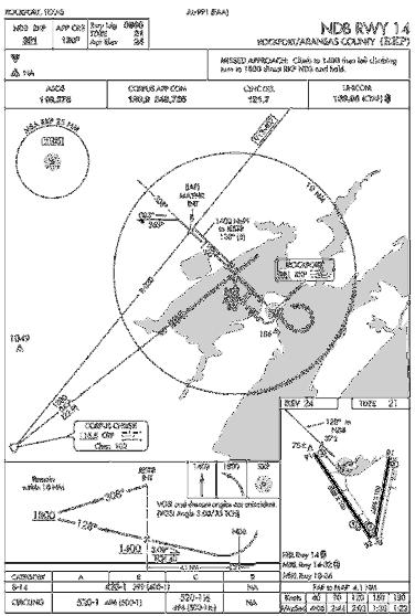
2 NDB Approach Background One of the oldest and most disliked approaches Can use NDBs both on and off of the destination airport NDB approaches can be on the TO or FROM side of an NDB; some use both the TO and FROM sides Navigation is based upon a specific bearing NDB approach may or may not have a final approach fix off airport NDB usually the final approach fix On airport NDB usually has no depicted FAF NDB is normally the IAF but can have others or none with radar It is a non-precision approach as there is no vertical guidance Requires situational awareness and subtle use of geometry MH + RB = MB 2


3 NDB Equipment ADF receiver and ADF radio bearing indicator (RBI) or radio magnetic indicator (RMI) Some approaches also require a VOR NAV receiver 3
 Flight timer or elapsed timer and reset button 4")
4 NDB Receiver Frequency Flight timer Power / identification volume control Tuning knob ADF function button Beat frequency oscillator (generates an audio tone to let you identify unmodulated NDBs that identify themselves using interruptedcarrier keying - seldom used in the United States) Flight timer or elapsed timer and reset button 4

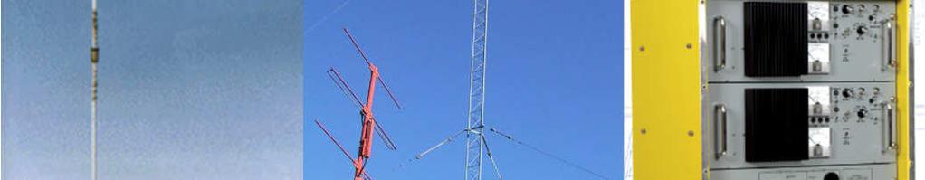
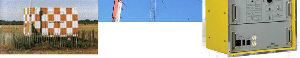
5 NDB Ground Station 5
6 Understanding the Signals Tune the NDB frequency Morse code identifier identify and keep it on in the background No other definitive evidence of signal loss (NDB 3 letters; LOM 2 letters) If equipped, press the test button to check equipment Indicator / Signal Errors Night effect: radio waves reflected back by the ionosphere can cause signal strength fluctuations 30 to 60 nautical miles from the transmitter, especially just before sunrise and just after sunset (more common on frequencies above 350 khz) Terrain / mountain effect: high terrain like mountains and cliffs can reflect radio waves, giving erroneous readings; magnetic deposits can also cause erroneous readings Electrical effect: electrical storms, and sometimes also electrical interference (from a ground-based source or from a source within the aircraft) can cause the ADF needle to deflect towards the electrical source Shoreline effect: low-frequency radio waves will refract or bend near a shoreline, especially if they are close to parallel to it Bank effect: when the aircraft is banked, the needle reading will be offset Quadrantal Error - Signal is bent by aircraft metal; quadrantal effect is minimal at the cardinal points (nose, tail and wing tips), and greater in the intermediate bearings; Needle Oscillation - transmissions; Needle oscillates in conditions of static (rainfall and thunderstorms) and weak Ore Deposits - Can cause needle deflections 6
7 Using the Radio Bearing Indicator (RBI) ADF indicator is a performance instrument Keep it in the scan Set the card to the course, if the RBI has a movable card Look at indicator for needle location and trend; BUT FLY THE ATTITUDE INDICATOR / DG don t chase the RBI Initially steer desired radial +/- wind correction Make corrections with gentle coordinated turns to reference headings on the DG using bracketing Make corrections early and often to avoid the need for large corrections Card Card adjuster knob 7

8 RBI Indications 8

9 Homing vs Flying a Course 9
10 Homing vs Flying a Course To home to a station using ADF: note the relative bearing to the NDB and turn the aircraft so that the relative bearing is on the aircraft s nose (i.e., the magnetic heading of the aircraft equals the magnetic bearing to the NDB); maintain a relative bearing of 360 (on the nose). To intercept a pre-determined track using ADF: orient the aircraft so that the aircraft s heading is the same as the desired track to or from the NDB (paralleling the track); note whether the indicator needle is indicating right or left of the longitudinal axis of the aircraft; if the bearing indicator points to the right of the aircraft s nose, add the desired intercept angle to the current orientated heading and fly the intercept; if the bearing indicator points to the left of longitudinal axis, subtract the desired intercept angle; if you are intercepting a track from the NDB, you slowly pull the tail of the RBI needle to match the intercept angle (turn toward where you want the TAIL of the needle to be) when the tail opens to match your intercept angle, you are on track ; if you are intercepting a track to the NDB, you slowly push the head of the bearing indictor to match the intercept angle (turn toward where you want the HEAD of the needle to be) when the head matches the intercept angle, you are on track. Now turn on course. 10
11 Let s Fly - IAF Starting the Approach Approach starts at the initial approach fix (IAF) There can be several IAF s IAFS join at one or more common intermediate segments You will reach the IAF from a feeder route which can be a radar vector Must fly the entire procedure unless otherwise advised by ATC 11
12 Let s Fly - IAF Starting the Approach IAF is where the initial approach segment begins. Purpose is to align the aircraft with the intermediate or final approach segment Accomplished by using a course reversal, such as a procedure turn or holding pattern, or straight in route IAF is usually a designated intersection, VOR, NDB, or DME fix IAF may be collocated with the intermediate fix of the instrument approach. In that case there is no initial approach segment Segment usually ends at the intermediate approach segment or at an Intermediate Fix (IF) 12
13 Let s Fly Intermediate Segment Starting the Approach Intermediate segment positions the aircraft for the final descent to the airport Normally aligned within 30 of the final approach course Segment begins when you are proceeding inbound to the FAF, are properly aligned with the final approach course, and are located within the prescribed distance before the FAF May not be charted Approach with a procedure turn is the most common example of an uncharted IF intermediate segment begins when you intercept the inbound course after completing the procedure turn Ends at beginning of Final approach 13
14 Let s Fly Final Segment Starting the Approach Final approach segment begins at a designated FAF, depicted as a Maltese cross (X) on the profile view, or at the point where the aircraft is established inbound on the final approach course Mandatory ATC report When leaving the FAF When you go missed in nonradar environment 14


15 Let s Fly Approach Segments Outer marker or other fix 15
16 Before the Initial Segment Preflight Plan the approach Must be familiar with all available information concerning a flight prior to departure and FDC Notams Enroute Get weather (ATIS, FSS information, etc.) to help determine likely approaches and review Calculate / review performance data, approach speeds, and power settings confirm aircraft and weather are appropriate for the ILS procedure for aircraft s certified category or, if higher, the actual speed to be flown Set navigation / communication and automation - The navigation equipment required for an approach is generally indicated by the title of the procedure and chart notes 16
17 Before the Initial Segment Review and brief the approach Don t forget to brief the missed approach Commit to memory Altitude step downs MDA Time from FAF to MAP or DME Visibility minimums Missed approach procedure (at least initial steps) Begin reducing speed Obtain ASOS/ATIS/AWOS on comm 2 listen in the background Note the time you cross the IAF 17
18 Initial Segment Complete briefing the approach Begin landing checklist complete before final segment Reset comm and nav radios with required frequencies Comply with the clearance and approach Finish reducing power to approach settings (consider wind gusts, shear and turbulence) Configure aircraft for landing Flaps Fuel related items set for landing (pumps, mixture, selectors) 18

19 Initial Segment - Briefing Brief and review approach to assure you can execute it - Complete before end of segment NDB identifier and frequency Final approach course Runway length, Touchdown Zone elevation and airport elevation Approach name Takeoff minimums / procedures non-standard Special notes often important! Missed approach information Frequencies Minimums for use as an alternate > nonstandard - - Can t be used as a legal alternate Dark = pilot controlled lighting; 19
20 Initial Segment - Briefing Plan view mentally run through the approach Procedure turn headings Heading for segment IAF with procedure turn Obstruction (highest) Distance and center identifier Holding course in and outbound Sector minimum safe altitude Center of MSA Feeder route Initial missed approach course 20
21 Initial Segment - Briefing Profile view mentally run through the approach Procedure turn notes FAF Graphical missed approach information Descent angle notes Outbound course Procedure turn altitude Non-precision FAF (point to begin MAP timing) Runway Minimums Inbound course FAF altitude Mileage to threshold Mileage from threshold to NDB Descent angle and threshold crossing height Aircraft category A <= 90 B < 121 C <
 Subtract headwind from airspeed (1/2 wind speed for quartering winds) Begin timing point MAP")
22 Segment - Briefing Missed Approach Timing Information (if ground speed information is unavailable estimate from airspeed) Add tailwind to airspeed (1/2 wind speed for quartering winds) Subtract headwind from airspeed (1/2 wind speed for quartering winds) Begin timing point MAP 22
23 Let s Fly The Initial Segment Radios tuned to NDB to 245 Confirm Morse code and leave on in the background Reduce power to approach setting Proceed on feeder at 2,000 feet Proceed outbound from the NDB to the procedure turn (1 4 minutes depending upon speed and NDB location) One minute outbound on procedure turn; Then turn inbound As the NDB needle begins to move towards 45 degree intercept angle (note the rate of movement) turn inbound on course (139 ) determine heading to hold with the wind correction angle 23
24 NDB Procedures On-Airport NDB You can tell NDB is on the airport from the approach chart profile view Generally an on airport NDB approach will have no depicted final approach fix. In which case, the final approach segment begins at the final approach point (FAP). The FAP is the point where you are established in-bound on the final approach course from the procedure turn/radar vector and can begin the final approach descent For a procedure turn fly out 3 to 4 minutes before the procedure turn to assure adequate distance to become established inbound The NDB is the MAP when the needle swings 180 no timing 24
25 Let s Fly The Intermediate Segment Switch to local frequency WHEN INSTRUCTED Complete landing checklist as much as possible You are now at the final segment! 25
26 Let s Fly The Final Segment At FAF (JESTR) start timing for missed approach (timing is based upon ground speed) Expeditious but safe descent (gen <700 ft 90 kts) However, if there is an angle of descent, you should calculate the corresponding rate of descent (inside back cover of TERPS) Maintain a constant speed level and descending FAF inbound report to ATC required in non-radar environment Likely to be told to switch to local frequency swap comm Confirm gear down Second notch flaps Check in white arc 26

27 Rate of Descent Table 27
28 Let s Fly The Final Segment Final speed reduction Glance out the window to look for the runway environment Begin level off about 100 before you reach the MDA 420 Airport Communications Tower Non-towered airport Broadcast your intentions on the CTAF Approach you are executing Your position (every mile for last 5 miles) Arrival over the FAF inbound Missed approach 28
29 Let s Fly The Final Segment If you now have an identifiable segment of the approach environment unmistakably visible and identifiable you may continue the approach if: Visibility is above the minimums for approach category You are in a position to make a normal descent to the intended runway using normal maneuvers FAR If not, commence missed approach turn - do not turn out early MAP identified by Needle swing 180 Time from NDB Other e.g. cross radial 29


30 Let s Fly The Final Segment Commence circle to land When aligned with final, drop full flaps and land At MAP: Runway environment in sight Visibility above minimums Able to make a normal descent to intended runway 30

31 NDB Approach Problems Report any instrument or communication malfunctions to ATC If signal loss or interference at any time, go missed but follow the course - do not turn out early Inoperative components No change in MDA Increase visibility requirements ¼ to ½ sm 31
32 Considerations If you are low generally do NOT climb level off and re-intercept Make small adjustments see what happens and readjust Remember sensitivity increases as you get near the NDB DO NOT FLY NDB needle bad things will happen! FLY the DG and AI With aircraft properly trimmed small changes in power will cause a pitch change and allow you to maintain airspeed Must execute missed after the MAP if you lose sighting of the runway environment Runway environment Approach lighting system not below 100 AGL until you see red side lights or red terminating bar Runway or runway markings or lights Threshold, threshold markings or lighting REILS VASI Touchdown zone or markings or lighting Know for the approach IAF and how to arrive at the FAF Minimum altitudes for each segment and MDA Missed approach procedure 32
33 Common Errors Failure to have essential approach information in memory IAF FAF Altitudes, including MDA MAP Poor communications Failure to complete checklist items or use checklist Descent below altitudes (keep a cushion on checkride) 33


34 QUESTIONS 34
NAVIGATION INTRUMENTATION ADF
 1. Introduction NAVIGATION INTRUMENTATION ADF The Automatic Direction Finding (ADF) equipment on-board of aircraft is used together with the Non Directional Beacon (NDB) transmitters installed on the ground.
VOR/DME APPROACH WITH A320
 1. Introduction VOR/DME APPROACH WITH A320 This documentation presents an example of a VOR/DME approach performed with an Airbus 320 at LFRS runway 21. This type of approach is a non-precision approach
Briefing the Approach
 Transcript Briefing the Approach Featuring: Doug Stewart Copyright PilotWorkshops.com, LLC. This material is available to members of the PilotWorkshops.com web site, which is the only place it can be legally
Chapter 10 Navigation
 Chapter 10 Navigation Table of Contents VHF Omnidirectional Range (VOR) VOR Orientation Course Determination VOR Airways VOR Receiver Check Points Automatic Direction Finder (ADF) Global Positioning System
This page is intentionally blank. GARMIN G1000 SYNTHETIC VISION AND PATHWAYS OPTION Rev 1 Page 2 of 27
 This page is intentionally blank. 190-00492-15 Rev 1 Page 2 of 27 Revision Number Page Number(s) LOG OF REVISIONS Description FAA Approved Date of Approval 1 All Initial Release See Page 1 See Page 1 190-00492-15
PERFORM A DME ARC. This document illustrates how to perform a DME arc with a HSI-equipped Beechcraft 90. Descent steps
 PERFORM A DME ARC 1. Introduction This document illustrates how to perform a DME arc with a HSI-equipped Beechcraft 90. 2. Preparatory work 2.1. Scenario You will need to open the following charts of Clermont
Integrated Cockpit Display System ICDS 1000 Pilot Operation Handbook
 Integrated Cockpit Display System ICDS 1000 Pilot Operation Handbook ICDS1000 Pilot Operating Handbook Revision 1.3 572-0540 page 1 Table Of Contents Electronic Attitude Direction Indicator (EADI)... 8
APPENDIX C VISUAL AND NAVIGATIONAL AIDS
 VISUAL AND NAVIGATIONAL AIDS APPENDIX C VISUAL AND NAVIGATIONAL AIDS An integral part of the airport system is the visual and navigational aids provided to assist pilots in navigating both on the airfield
Instrument Flight Procedures - Glass Cockpits
 Instrument Flight Procedures - Glass Cockpits The concepts contained here are general in nature and can be used by all however, they are targeted toward glass cockpits and, more specifically, integrated
not authorized for IFR use. authorized for IFR use under VMC. authorized for IFR use under IMC until the runway is in sight.
 Gleim FAA Test Prep: Instrument Pilot (20 questions) Name: Date: Circle the correct answer on the question sheets AND fill in the corresponding circle on the separate answer sheet. [1] Gleim #: 3.4.32
Navigation Systems - Enroute. Nolan, Chap 2
 Navigation Systems - Enroute Nolan, Chap 2 1 En-route Navigation Visual Flight Rules Instrument Flight Rules Pilotage/Dead-Reckoning Land-based Space-based Aircraft-based Aeronautic Charts Forecast Wind
Fokker 50 - Automatic Flight Control System
 GENERAL The Automatic Flight Control System (AFCS) controls the aircraft around the pitch, roll, and yaw axes. The system consists of: Two Flight Directors (FD). Autopilot (AP). Flight Augmentation System
Navigation Systems. Chapter 7. Introduction. Ground Wave. Basic Radio Principles
 Chapter 7 Navigation Systems Introduction This chapter provides the basic radio principles applicable to navigation equipment, as well as an operational knowledge of how to use these systems in instrument
ADF-650D Automatic Direction Finder System Pilot s Operating Handbook
 ADF-650D Automatic Direction Finder System Pilot s Operating Handbook V O L 1.1 2 0 MHz ADF List of Effective Pages * Asterisk indicates pages changed, added, or deleted by revision. Record of Revisions
Understanding VOR's, VORTAC's and How To Use Them
 Understanding VOR's, VORTAC's and How To Use Them by Hal Stoen Used by California Airlines (CAX) with permission from Hal Stoen 1998 first release: 2 December, 1998 INTRODUCTION The practical aspects of
The Training Database is supplied as part of the RNS, and is loaded at the same time as the main program.
 THE TRAINING DATABASE The Training Database is supplied as part of the RNS, and is loaded at the same time as the main program. The Training Area is fictious, but the procedures are representative of the
Mode 4A Unsafe terrain clearance with landing gear not down and flaps not in landing position
 1.6.18 Ground Proximity Warning System Allied Signal Aerospace (Honeywell) manufactures the GPWS, part number 965-0648- 008. The GPWS provides the following alerts if thresholds are exceeded: Mode 1 Excessive
2 VHF DIRECTION FINDING
 2 VHF DIRECTION FINDING This chapter explains the principle of operation and the use of the VHF Ground Direction Finding (VDF). VDF provides means of determining the aircraft bearing from a ground station.
NAVIGATION INSTRUMENTS - BASICS
 NAVIGATION INSTRUMENTS - BASICS 1. Introduction Several radio-navigation instruments equip the different airplanes available in our flight simulators software. The type of instrument that can be found
Table of Contents. Introduction 3. Pictorials of the 40 and 50 Systems 4. List of Applicable Acronyms 6
 Table of Contents Introduction 3 Pictorials of the 40 and 50 Systems 4 List of Applicable Acronyms 6 System 40 Modes of Operation 7 System 40 Functional Preflight Procedures 10 System 40 In Flight Procedures
INTERCEPT NDB TRACK. This documentation will present an example of NDB track interception performed with a Beechcraft BE90.
 1. Introduction INTERCEPT NDB TRACK This documentation will present an example of NDB track interception performed with a Beechcraft BE90. 2. Initial situation The initial situation is: 1. The aircraft
KAP 140 Two Axis with Altitude Preselect Operation
 Two Axis/Altitude reselect Operations K 0 Two Axis with Altitude reselect Operation The K 0 is a digital, panel-mounted autopilot system for light aircraft. 7 8 K 0 D AV V AT D Two-axis w/altitude reelect
SAARBRÜCKEN Germany (EDDR)
") Hangars 1 2 For flight simulator use only. Not to be used for real world flight. 27 Germany () 27 Area of competency apron control Area of competency DFS TWR Terminal B 09 Noise abetement facility for
Hangars 1 2 For flight simulator use only. Not to be used for real world flight. 27 Germany () 27 Area of competency apron control Area of competency DFS TWR Terminal B 09 Noise abetement facility for
MILITARY AERONAUTICAL INFORMATION PUBLICATION (M.A.I.P.) LOW ALTITUDE BALKANS THEATER - FALCON BMS 4.33
 LOW ALTITUDE BALKANS THEATER - FALCON BMS 4.33") MILITARY AERONAUTICAL INFORMATION PUBLICATION (M.A.I.P.) LOW ALTITUDE AIRPORT DIAGRAMS STANDARD INSTRUMENT DEPARTURES (SID) INSTRUMENT APPROACH PROCEDURES (IAP) BALKANS THEATER - FALCON BMS 4.33 Created
MILITARY AERONAUTICAL INFORMATION PUBLICATION (M.A.I.P.) LOW ALTITUDE AIRPORT DIAGRAMS STANDARD INSTRUMENT DEPARTURES (SID) INSTRUMENT APPROACH PROCEDURES (IAP) BALKANS THEATER - FALCON BMS 4.33 Created
INSTALLATION MANUAL AND OPERATING INSTRUCTIONS
 INSTALLATION MANUAL AND OPERATING INSTRUCTIONS MD200-202/203/206/207 Series COURSE DEVIATION INDICATOR Mid-Continent Instruments and Avionics Manual Number 8017702 9400 E. 34 th Street N. Wichita, KS 67226
How to Intercept a Radial Outbound
 How to Intercept a Radial Outbound by Greg Whiley Another practical publication from Aussie Star Flight Simulation How to intercepting a radial outbound 1 Greg Whiley Aussie Star Flight Simulation How
Navigation Equipment. Pilotage and Dead Reckoning. Navigational Aids. Radio Waves
 1 Navigation Equipment Successful air navigation not only involves piloting an aircraft from place to place, but also not getting lost, not breaking any FAA regulations, and not endangering the safety
AIRCRAFT AVIONIC SYSTEMS
 AIRCRAFT AVIONIC SYSTEMS B-777 cockpit Package C:\Documents and ettings\administrato Course Outline Radio wave propagation Aircraft Navigation Systems - Very High Omni-range (VOR) system - Instrument Landing
SD3-60 AIRCRAFT MAINTENANCE MANUAL - DESCRIPTION & OPERATION (PRE-MOD A8062) (1) Transceiver, Collins type DME40, (Part No.
 (1) Transceiver, Collins type DME40, (Part No.") AMM 53.0.0.0DME SYSTEM - DESCRIPTION & OPERATION (PRE-MOD A8062) 1. Description A. General Two identical D.M.E. systems are installed, one for each pilot. Frequency selection is made via each respective
AMM 53.0.0.0DME SYSTEM - DESCRIPTION & OPERATION (PRE-MOD A8062) 1. Description A. General Two identical D.M.E. systems are installed, one for each pilot. Frequency selection is made via each respective
Digiflight II SERIES AUTOPILOTS
 Operating Handbook For Digiflight II SERIES AUTOPILOTS TRUTRAK FLIGHT SYSTEMS 1500 S. Old Missouri Road Springdale, AR 72764 Ph. 479-751-0250 Fax 479-751-3397 Toll Free: 866-TRUTRAK 866-(878-8725) www.trutrakap.com
- FlightGear Autopilot and Route-Manager -
 - FlightGear 747-400 Autopilot and Route-Manager - General This documentation is valid for the version of 747-400 from 'buster' (http://flightgear.azuana.de). Our aircraft can be controlled by two different
I3101 WORKSHEET. Prerequisites: -IN1203-4, IN1206-7, IN , and IN (Instruments CAI) -Q4390 (NATOPS check-ride)
 -Q4390 (NATOPS check-ride)") I3101 WORKSHEET Planned Route: Takeoff: KNPA, RWY 25R Altitude: 6000 Route: Radar departure from KNPA BFM (VOR holding) SQWID Approaches: KMOB VOR-A (arcing approach), KMOB RVFAC ILS RWY 15 KMOB RVFAC
I3101 WORKSHEET Planned Route: Takeoff: KNPA, RWY 25R Altitude: 6000 Route: Radar departure from KNPA BFM (VOR holding) SQWID Approaches: KMOB VOR-A (arcing approach), KMOB RVFAC ILS RWY 15 KMOB RVFAC
Human Factors Implications of Continuous Descent Approach Procedures for Noise Abatement in Air Traffic Control
 Human Factors Implications of Continuous Descent Approach Procedures for Noise Abatement in Air Traffic Control Hayley J. Davison Reynolds, hayley@mit.edu Tom G. Reynolds, tgr25@cam.ac.uk R. John Hansman,
INSTALLATION MANUAL AND OPERATING INSTRUCTIONS
 INSTALLATION MANUAL AND OPERATING INSTRUCTIONS MD200-302/303/306/307 Series COURSE DEVIATION INDICATOR MID-CONTINENT INST. CO., INC MANUAL NUMBER 8017972 Revisions Rev. Date Description of Change ECO#
Page K1. The Big Picture. Pilotage
 Page K1 Pilotage 1. [K1/3/2] Pilotage is navigation by A. reference to flight instruments. B. reference to landmarks. C. reference to airborne satellites. Electronic Elucidation The Big Picture 3. [K4/2/1]
VT-27 Formation Script
 1 VT-27 Formation Script Cockpit Checklist (BOTH) o Input briefed VHF Tactical Frequency (123.47, 123.57, or 123.67) (BOTH) LEAD: -Tac Call Sign- One is ready to close canopy on VHF Tactical Frequency
VOR = VHF Omni-directional Radio Range. Cockpit instrument. Navigation charts Different types. What comes to mind?
 VOR = VHF Omni-directional Radio Range What comes to mind? Cockpit instrument Navigation charts Different types 15-12-2009 VOR 1 VOR training BE V.2.1226 p1 FMC, does not come to mind, although it could
CHANGE 1 CHAPTER FOUR - TACAN AND VOR NAVIGATION...
 CHANGE 1 CHAPTER FOUR - TACAN AND VOR NAVIGATION... 4-1 400. INTRODUCTION... 4-1 401. LESSON TOPIC LEARNING OBJECTIVES... 4-1 402. VOR - TACAN PROCEDURES AND OPERATING INSTRUCTIONS... 4-2 403. HOLDING...
GRT Autopilot User Guide. All GRT EFIS Systems
 All GRT EFIS Systems Revision A 22-May-2014 Copyright 2014 3133 Madison Ave. SE Wyoming, MI 49548 (616) 245-7700 www.grtavionics.com Revision Notes Revision Date Change Description A 22-May-2014 Complete
FlyRealHUDs Very Brief Helo User s Manual
 FlyRealHUDs Very Brief Helo User s Manual 1 1.0 Welcome! Congratulations. You are about to become one of the elite pilots who have mastered the fine art of flying the most advanced piece of avionics in
DME I-GH & I-UY Freq-paired NDB GUY 361 ILS LLZ I-GH ILS LLZ I-UY PAPI (3 ) MEHT m x 45m Asphalt. TwyB Hold PAPI (3 ) MEHT 47
 MEHT m x 45m Asphalt. TwyB Hold PAPI (3 ) MEHT 47") AERODROME CHART - ICAO 002 3700W ELEVATIONS IN FEET AMSL... HEIGHTS IN FEET ABOVE AD... (51) 002 3630W 002 0W 002 3530W (12 May 05) AD 2--2-1 492606N 0027W ELEV 387 N 492630N 492630N 320 330 ILS LLZ I-GH
AERODROME CHART - ICAO 002 3700W ELEVATIONS IN FEET AMSL... HEIGHTS IN FEET ABOVE AD... (51) 002 3630W 002 0W 002 3530W (12 May 05) AD 2--2-1 492606N 0027W ELEV 387 N 492630N 492630N 320 330 ILS LLZ I-GH
FAA APPROVED AIRPLANE FLIGHT MANUAL SUPPLEMENT FOR. Trio Pro Pilot Autopilot
 Page 1 480 Ruddiman Drive TRIO AP Flight Manual Supplement North Muskegon, MI 49445 L-1006-01 Rev D FOR Trio Pro Pilot Autopilot ON Cessna 172, 175, 177, 180, 182, 185 and Piper PA28 Aircraft Document
CIVIL AVIATION REQUIREMENTS SECTION 4 - AERODROME STANDARDS & AIR TRAFFIC SERVICES SERIES 'D', PART II 12 TH JULY 2006 EFFECTIVE: FORTHWITH
 GOVERNMENT OF INDIA OFFICE OF DIRECTOR GENERAL OF CIVIL AVIATION TECHNICAL CENTRE, OPP SAFDARJANG AIRPORT, NEW DELHI CIVIL AVIATION REQUIREMENTS SECTION 4 AERODROME STANDARDS & AIR TRAFFIC SERVICES SERIES
ELITE Operator s Manual
 ELITE Jet v8 ELITE Operator s Manual The aircraft simulated by ELITE Jet represents the well known civil airliner MD-81. The instrumentation of the cockpit represents all standard instruments. Only the
2 Flight Plans 1 Fill in the appropriate boxes 2 Find acceptable routes 3 Useful Newbie Comments
 VATSIM Requirement 1 Download and install essential software 1 Your Sim MSFS, XPlane 2 Pilot Clients SB, FSInn 3 To find ATC Wazzaup, Servinfo, VATSpy, VATSIM Stats, Pilot Client 4 Interpreting This Requirement
Operating Handbook For FD PILOT SERIES AUTOPILOTS
 Operating Handbook For FD PILOT SERIES AUTOPILOTS TRUTRAK FLIGHT SYSTEMS 1500 S. Old Missouri Road Springdale, AR 72764 Ph. 479-751-0250 Fax 479-751-3397 Toll Free: 866-TRUTRAK 866-(878-8725) www.trutrakap.com
Digiflight II SERIES AUTOPILOTS
 Operating Handbook For Digiflight II SERIES AUTOPILOTS TRUTRAK FLIGHT SYSTEMS 1500 S. Old Missouri Road Springdale, AR 72764 Ph. 479-751-0250 Fax 479-751-3397 Toll Free: 866-TRUTRAK 866-(878-8725) www.trutrakap.com
INSTALLATION MANUAL KI 208, KI 209 NAVIGATION INDICATORS
 RELEASED FOR THE EXCLUSIVE USE BY: AIRCRAFT ELECTRONICS ASSOCIATION h INSTALLATION MANUAL KI 208, KI 209 NAVIGATION INDICATORS MANUAL NUMBER 006-00140-0004 Revision 4, August 2002 RELEASED FOR THE EXCLUSIVE
AUTOMATIC FLIGHT CONTROL SYSTEM
 TRIDEN AUTOMATIC FLIGHT CONTROL SYSTEM PILOT S OPERATING HANDBOOK 68S1135 Rev B 02-05-03 FACTORY SERVICE CENTERS Century Flight Systems, Inc. has established Factory owned and operated Customer Service
SD3-60 AIRCRAFT MAINTENANCE MANUAL
 AMM 24.0.0.0FLIGHT DIRECTOR SYSTEM - DESCRIPTION & OPERATION 1. Description A. General Refer to Figure 1. Identical, left and right, systems are installed (one for each pilot); each provides information
Airfield Obstruction and Navigational Aid Surveys
 Section I. Section II. Section III. Section IV. Section V. Chapter 7 Airfield Obstruction and Navigational Aid Surveys The purpose of this chapter is to acquaint the Army surveyor with the terminologies
Apollo GPS Database Addendum
 Apollo GPS Database Addendum This document includes information that has been added to the waypoint database after the printing of the user s guide. A new waypoint type has been added to your database
FOUND FBA-2C1/2C2 BUSH HAWK EQUIPPED WITH SINGLE GARMIN GNS-430 # 1 VHF-AM COMM / VOR-ILS / GPS RECEIVER
 FOUND SUPPLEMENT M400-S11 Transport Canada Approved Flight Manual Supplement For FOUND BUSH HAWK EQUIPPED WITH SINGLE # 1 VHF-AM COMM / VOR-ILS / GPS RECEIVER Section 1 General is Unapproved and provided
Page Chg
 Page Chg Cover...0 Page #...1 TOC-1...1 TOC-2..1 1-1.1 1-2.1 1-3.1 1-4...0 1-5...1 1-6. 1 1-7. 1 1-8. 1 1-9. 1 1-10...1 1-11..1 1-12..1 1-13..1 1-14..1 2-1.0 2-2.0 2-3.1 Page Chg 2-4.0 3-1.0 3-2.0 3-3.0
Post-Installation Checkout All GRT EFIS Models
 GRT Autopilot Post-Installation Checkout All GRT EFIS Models April 2011 Grand Rapids Technologies, Inc. 3133 Madison Avenue SE Wyoming MI 49548 616-245-7700 www.grtavionics.com Intentionally Left Blank
Dash8 - Q400 - Autoflight
 12.3.1 Introduction The Automatic Flight Control System (AFCS), provides fail-safe operation of flight director guidance, autopilot, yaw damper and automatic pitch trim functions. 12.3.2 General The Automatic
Dash8-200/300 - Automatic Flight AUTOMATIC FLIGHT CONTROLS AND INDICATORS. Page 1
 AUTOMATIC FLIGHT CONTROLS AND INDICATORS FLIGHT GUIDANCE MODE SELECTORS (alternate action) - Engages flight director modes of operation. - Flight director command bars display lateral and/or vertical guidance
P/N 135A FAA Approved: 7/26/2005 Section 9 Initial Release Page 1 of 10
 FAA APPROVED AIRPLANE FLIGHT MANUAL SUPPLEMENT FOR GARMIN GNS 430 - VHF COMM/NAV/GPS Serial No: Registration No: When installing the Garmin GNS 430 - VHF COMM/NAV/GPS in the Liberty Aerospace XL2, this
INSTALLATION MANUAL AND OPERATING INSTRUCTIONS
 INSTALLATION MANUAL AND OPERATING INSTRUCTIONS MD222-( ) SERIES TWO-INCH COURSE DEVIATION INDICATOR Mid-Continent Instruments and Avionics Manual Number 9016311 9400 E. 34 th Street N. Wichita, KS 67226
GNS 430 Basic Usage. VFR GPS Usage
 GNS 430 Basic Usage VFR GPS Usage Disclaimer This briefing is to designed to give an introductory overview so that as you read the GNS 430 Pilot s Guide and Reference you will have a basic understanding
Alsim Simulation Operating Instructions
 Alsim Simulation Operating Instructions Overview of Simulation This Alsim simulation is primarily designed to familiarize you with the avionics in the Alsim MCC200 Flight Simulator. The avionics and autopilot
For Microsoft FSX and FS FriendlyPanels. All right reserved
 FriendlyPanels Software (version 2.0) For Microsoft FSX and FS9 2007 FriendlyPanels. All right reserved FOURTEEN GAUGES FOR YOUR FSX and FS9 AIRCRAFT 1 1. Introduction. 2. Requirements 3. Installing the
KMD 550/850. Traffic Avoidance Function (TCAS/TAS/TIS) Pilot s Guide Addendum. Multi-Function Display. For Software Version 01/13 or later
 Pilot s Guide Addendum. Multi-Function Display. For Software Version 01/13 or later") N B KMD 550/850 Multi-Function Display Traffic Avoidance Function (TCAS/TAS/TIS) Pilot s Guide Addendum For Software Version 01/13 or later Revision 3 Jun/2004 006-18238-0000 The information contained
N B KMD 550/850 Multi-Function Display Traffic Avoidance Function (TCAS/TAS/TIS) Pilot s Guide Addendum For Software Version 01/13 or later Revision 3 Jun/2004 006-18238-0000 The information contained
AERONAUTICAL CHARTS. ordering is available at the National Aeronautical Charting Office (NACO) Web site:
 Web site:") This chapter provides an introduction to crosscountry flying under visual flight rules (VFR). It contains practical information for planning and executing cross-country flights for the beginning pilot.
This chapter provides an introduction to crosscountry flying under visual flight rules (VFR). It contains practical information for planning and executing cross-country flights for the beginning pilot.
Introduction to: Radio Navigational Aids
 Introduction to: Radio Navigational Aids 1 Lecture Topics Basic Principles Radio Directional Finding (RDF) Radio Beacons Distance Measuring Equipment (DME) Instrument Landing System (ILS) Microwave Landing
SkyView. Autopilot In-Flight Tuning Guide. This product is not approved for installation in type certificated aircraft
 SkyView Autopilot In-Flight Tuning Guide This product is not approved for installation in type certificated aircraft Document 102064-000, Revision B For use with firmware version 10.0 March, 2014 Copyright
II.C. Visual Scanning and Collision Avoidance
 References: FAA-H-8083-3; FAA-8083-3-25; AC 90-48; AIM Objectives Key Elements Elements Schedule Equipment IP s Actions SP s Actions Completion Standards The student should develop knowledge of the elements
17 Wellington Business Park Crowthorne Berkshire RG45 6LS England. Tel: +44 (0)
") 17 Wellington Business Park Crowthorne Berkshire RG45 6LS England Tel: +44 (0) 1344 234047 www.flightdatapeople.com Information Sheet www.flightdatapeople.com Commercial in Confidence Hosted Flight Data
17 Wellington Business Park Crowthorne Berkshire RG45 6LS England Tel: +44 (0) 1344 234047 www.flightdatapeople.com Information Sheet www.flightdatapeople.com Commercial in Confidence Hosted Flight Data
JEPPESEN 10-1R 30NM 20NM 10NM. Cochin 10NM 10NM COCHIN RADAR
 Printed from JeppView for Windows 5.3.. on 7 May 7; Terminal chart data cycle -7 (Expired); Notice: After 9 Feb 7, Z, this chart may no longer be valid VOI/OK INTL JAN 4 -R, INIA.RAAR.MINIMUM.ALTITUES.
Cockpit Voice Recorder Intelligibility Analysis Flight Test Procedures
 Registration: Serial #: Model: Date: Important Note To Flight Crew The procedures detailed in this report are intended to demonstrate that the CVR records the required information. Failure to follow each
Operating Handbook. For. Gemini Autopilot
 Operating Handbook For Gemini Autopilot TRUTRAK FLIGHT SYSTEMS 1488 S. Old Missouri Road Springdale, AR 72764 Ph. 479-751-0250 Fax 479-751-3397 www.trutrakap.com Table of Contents 1. Revisions... 5 2.
Detrum GAVIN-8C Transmitter
 Motion RC Supplemental Guide for the Detrum GAVIN-8C Transmitter Version 1.0 Contents Review the Transmitter s Controls... 1 Review the Home Screen... 2 Power the Transmitter... 3 Calibrate the Transmitter...
Automatic Dependent Surveillance -ADS-B
 ASECNA Workshop on ADS-B (Dakar, Senegal, 22 to 23 July 2014) Automatic Dependent Surveillance -ADS-B Presented by FX SALAMBANGA Regional Officer, CNS WACAF OUTLINE I Definition II Principles III Architecture
Toward an Integrated Ecological Plan View Display for Air Traffic Controllers
 Wright State University CORE Scholar International Symposium on Aviation Psychology - 2015 International Symposium on Aviation Psychology 2015 Toward an Integrated Ecological Plan View Display for Air
Scientific Journal of Silesian University of Technology. Series Transport Zeszyty Naukowe Politechniki Śląskiej. Seria Transport
 Scientific Journal of Silesian University of Technology. Series Transport Zeszyty Naukowe Politechniki Śląskiej. Seria Transport Volume 93 2016 p-issn: 0209-3324 e-issn: 2450-1549 DOI: https://doi.org/10.20858/sjsutst.2016.93.13
SmartFly Cirrus Cirrus. Flight Trainer
 SmartFly SmartFly Cirrus Cirrus Flight Trainer The new PX-Eco Professional BATD Flight Simulator was engineered from the bottom up with a robust mechanism and our new SIMSOFT USB Digital Hardware Controller.
JeppView for Windows. General Information. Runway Information. Communication Information. jep=jeppesen
 Airport Information For VOGO Printed on 27 Jan 208 Page (c) SANERSON, INC., 208, ALL RIGHTS RESERVE jep= JeppView for Windows General Information Location: IN ICAO/IATA: VOGO / GOI Lat/Long: N5 22.85',
9.1 General. f-i TABLE OF CONTENTS SECTION 9 SUPPLEMENTS REPORT: VB-880
 TABLE OF CONTENTS Paragraph/ Supplement No. 9.1 General Page No. 9-1 I z J 4 5 6 AutoFIite II Autopilot Installation 9-3 AutoControl IIIB Autopilot Installation 9-5 Piper Electric Pitch Trim 9-9 Air Conditioning
FLIGHT INSPECTION OF NATO RADIO / RADAR NAVIGATION AND APPROACH AIDS
 FLIGHT INSPECTION OF NATO RADIO / RADAR NAVIGATION AND APPROACH AIDS JUNE 2006 THIS PAGE IS INTENTIONALLY LEFT BLANK THIS PAGE IS INTENTIONALLY LEFT BLANK - iv - RECORD OF CHANGES Change Date Date Entered
A Nugget's Guide to HUD-Symbology
 A Nugget's Guide to HUD-Symbology Rev 2, 02/19/2006, Chewbakka, www.tattoine-skyworx.de Do you remember what all the little numbers in the different modes of the HUD mean? Well you should, because they're
Basic GPS Operation. by Greg Whiley. Another practical publication from Aussie Star Flight Simulation
 Basic GPS Operation by Greg Whiley Another practical publication from Aussie Star Flight Simulation INTENTIONALLY LEFT BLANK Aussie Star Flight Simulation 2 Basic GPS Operations Statement of copyright
Database Coding and Publication
 MIXED MODE Database Coding and Publication Sorin-Dan Onitiu Jeppesen 17 October 2012 An inter-disciplinary overview of PBN design, coding and charting 1 Issue: Chart, Database, and Avionics Harmonization
EMBRAER 135/145 Autopilot
 EMBRAER 135/145 Autopilot GENERAL The Primus 1000 (P-1000) Automatic Flight Control System (AFCS) is a fully integrated, fail passive three-axis flight control system which incorporates lateral and vertical
491229N W DME I-DD. Freq-paired. Anemometer PAPI (3 ) MEHT 55. Fire Station. Hold. Twy E. Hold E Hold C2. Twy A (40) (62) Terminal Building
 MEHT 55. Fire Station. Hold. Twy E. Hold E Hold C2. Twy A (40) (62) Terminal Building") AERODROME CHART - ICAO ELEVATIONS IN FEET AMSL... HEIGHTS IN FEET ABOVE AD... (121) 491229N 0021144W 002 1230W 002 1200W 002 1130W ELEV 002 1100W (1 Sep 05) AD 2--2-1 491300N N 491300N 491230N 09 Displaced
AERODROME CHART - ICAO ELEVATIONS IN FEET AMSL... HEIGHTS IN FEET ABOVE AD... (121) 491229N 0021144W 002 1230W 002 1200W 002 1130W ELEV 002 1100W (1 Sep 05) AD 2--2-1 491300N N 491300N 491230N 09 Displaced
Circle the correct answer on the question sheets and fill in the corresponding circle on the separate answer sheet.
 Gleim FAA Test Prep: Instrument Pilot (20 questions) IPGS Study Unit 3: Navigation Systems (IFH Ch 7, PHAK Ch 15) Name: Date: Circle the correct answer on the question sheets and fill in the corresponding
SECTION 2-19 AUTOPILOT
 AIRPLANE SECTION 2-19 Block General...2-19-05...01 Automatic Flight Control System...2-19-05...02 Flight Guidance System...2-19-05...04 Flight Director...2-19-05...04 Autopilot...2-19-05...04 Flight Director
RADIO NAVIGATION
 details and associated Learning Objectives ATPL CPL ATPL/ ATPL CPL 062 00 00 00 RADIO NAVIGATION 062 01 00 00 BASIC RADIO PROPAGATION THEORY 062 01 01 00 Basic principles 062 01 01 01 Electromagnetic waves
MGL Avionics. iefis. Integrated Autopilot. User and installation manual. Manual dated 14 November Page 1
 MGL Avionics iefis Integrated Autopilot User and installation manual Manual dated 14 November 2014 Page 1 Table of Contents General...4 Autopilot abilities...4 External autopilot systems...4 Internal autopilot
G1000 Integrated Flight Deck. Cockpit Reference Guide for the Cessna Citation Mustang
 G1000 Integrated Flight Deck Cockpit Reference Guide for the Cessna Citation Mustang FLIGHT INSTRUMENTS NAV/COM/TRANSPONDER/AUDIO PANEL AUTOMATIC FLIGHT CONTROL SYSTEM GPS NAVIGATION FLIGHT PLANNING PROCEDURES
NAVIGATION (2) RADIO NAVIGATION
 RADIO NAVIGATION") 1 An aircraft is "homing" to a radio beacon whilst maintaining a relative bearing of zero. If the magnetic heading decreases, the aircraft is experiencing: A left drift B right drift C a wind from the
1 An aircraft is "homing" to a radio beacon whilst maintaining a relative bearing of zero. If the magnetic heading decreases, the aircraft is experiencing: A left drift B right drift C a wind from the
Detrum MSR66A Receiver
 Motion RC User Guide for the Detrum MSR66A Receiver Version 1.0 Contents Review the Receiver s Features... 1 Review the Receiver s Ports and Connection Orientation... 2 Bind the Receiver to a Transmitter
The prior specification for navaid data was XP NAV810, which was compatible with X-Plane Changes in the spec for XP NAV1100 were:
 X-PLANE NAVIGATION DATA FOR NAVAIDS (USER_NAV.DAT & EARTH_NAV.DAT) FILE SPECIFICATION VERSION 1100 REVISION HISTORY 7 May 2009 Spec converted to this new format to support new web site (http://data.x-plane.com).
Operations Manual. Caution: Preliminary
 Operations Manual Caution: Preliminary This manual is incomplete at this time. Most, but not all of the data within the manual is accurate, although it is all subject to change and may not match the software
WARNING This operating manual has been writen to be used only with Microsoft Flight Simulator. FriendlyPanels
 FriendlyPanels Software WARNING This operating manual has been writen to be used only with Microsoft Flight Simulator. FriendlyPanels www.friendlypanels.net fpanels@friendlypanels.net 1. INTRODUCTION This
Copyrighted Material - Taylor & Francis
 22 Traffic Alert and Collision Avoidance System II (TCAS II) Steve Henely Rockwell Collins 22. Introduction...22-22.2 Components...22-2 22.3 Surveillance...22-3 22. Protected Airspace...22-3 22. Collision
EE Chapter 14 Communication and Navigation Systems
 EE 2145230 Chapter 14 Communication and Navigation Systems Two way radio communication with air traffic controllers and tower operators is necessary. Aviation electronics or avionics: Avionic systems cover
Page Chg
 Page Chg Cover...0 Page #...2 TOC-1...2 TOC-2..2 1-1 2 1-2.2 1-3.2 1-4...2 1-5...2 1-6. 2 1-7. 2 1-8. 2 1-9. 2 1-10...2 1-11..2 1-12..2 1-13..2 1-14..2 1-15..2 1-16..2 1-17..2 1-18...2 2-1.0 2-2.0 2-3.2
Operating Handbook. For. Gemini Autopilot
 Operating Handbook For Gemini Autopilot TRUTRAK FLIGHT SYSTEMS 1488 S. Old Missouri Road Springdale, AR 72764 Ph. 479-751-0250 Fax 479-751-3397 www.trutrakap.com Table of Contents 1. Revisions... 5 2.
MOONEY AIRCRAFT CORPORATION P. 0. Box 72 Kerrville, Texas FAA APPROVED
 P. 0. Box 72 Kerrville, Texas 78029 FAA APPROVED AIRPLANE FLIGHT MANUAL SUPPLEMENT FOR MOONEY M20J, M20K, M20L, M20M, M20R with Aircraft Serial No. Aircraft Reg. No. This supplement must be attached to
MGL Avionics. Odyssey/Voyager G2 and iefis
 MGL Avionics Odyssey/Voyager G2 and iefis Navigation This document applies to G2 version 1.1.0.1 or later, iefis 1.0.0.3 or later. Note: This document is based on the G2. The iefis system provides identical