RotoLine Rotary Encoders. Magnetic rotary encoders Optical rotary encoders Geared potentiometers. Platzhalter Titel. Siehe Umschlagdatei RotoLine
|
|
|
- Shonda Richardson
- 6 years ago
- Views:
Transcription

1 RotoLine Rotary Encoders 2 Magnetic rotary encoders Optical rotary encoders Geared potentiometers Platzhalter Titel Siehe Umschlagdatei RotoLine


2 2 SIKO Precision in Motion Success is the result of a commitment to precision, innovation and customer benefit Precision is SIKO s top priority and standard! True to this philosophy, SIKO has been developing and producing innovative solutions in distance and angle measurement technology for more than 45 years now. ased in uchenbach in the foothills of the lack Forest, the company produces its own measurement technologies, which are a global success in all areas of mechanical engineering. Even today, SIKO s core concept is still manifest in its innovative power, product development and company spirit. Since taking over the business in 1990, industrial engineer Horst Wandres, son of its founder, has continued to develop this philosophy with impressive results. Intelligent solutions Attentive ears will always find the right solution. Automation and process optimization are the cornerstones of SIKO s ambitious new technologies and goaloriented measurement solutions. The company pursues a clear, consistent line of development, ranging from digital position indicators and handwheels through incremental encoders, absolute encoders and measurement displays to future-oriented technologies with electronically programmable or magnetic measurement systems (MagLine). SIKO again follows the road to success with its compact, ultra-resilient actuators (DriveLine), which enable automated adjustment of machine axles. 6 distinctive product lines PositionLine Mechanical and electronic position indicators, handwheels with analog indicators, control knobs RotoLine Magnetic and optical encoders, geared potentiometers LinearLine Wire-actuated encoders DriveLine Actuators MagLine Magnetic length and angle measurement systems DisplayLine Measurement displays Consistent teamwork The secret of SIKO s development prowess lies in the motivation and team spirit of its workers. SIKO has a conscious policy of integrating the experiences of its 170 employees, which has a dynamic effect on all areas of company life. Outstanding individual performances blend together to enhance the efficiency of the whole organization. Not one for all but all together this motto typifies SIKO s synergetic development process, delivering solutions which dominate the market in all aspects of measurement technology in mechanical engineering. This is SIKO today. Precision in motion, dynamic and open for the future We speak the same language: At SIKO, a willingness to participate in open dialog enhances engineering performance. Our production site advantages are not interchangeable. 2 RotoLine
3 RotoLine Table of contents 3 RotoLine Product Overview 4 Magnetic rotary encoders 6 Optical rotary encoders 40 Geared potentiometers 60 Accessories 86 Product index, Contact information 96 2 RotoLine

.")
4 4 RotoLine Product Overview Rotary encoders: Precise measuring technology with defined values SIKO has united the rotary encoder range under the name of RotoLine. There are the following three product categories, depending on the measuring principle employed in their typical applications: Magnetic rotary encoders Optical rotary encoders Geared potentiometers Mounted on a shaft or spindle, they track measured values as incremental or absolute signals. The measuring principle can either be optical, magnetic or based on an electrical resistance (geared potentiometer). The information obtained is then available for higher-level controllers or direct display on indicators (refer to catalog 6 DisplayLine). The comprehensive SIKO product knowhow permits a wide selection of types ranging from inexpensive rotary encoders in miniature format with simpler mechanical designs to sophisticated, high resolution products in housings made of plastic or tough die-cast aluminum. SIKO rotary encoders are essential for tracking lengths, angles and speed in machines and systems. With a host of different designs and customized application specifications, rotary encoders serve as the basis for robust measuring processes for a wide range of different mechanical engineering applications. Incremental marking Magnetic rotary encoders Magnetic or optical measurement? Under extreme industrial conditions the magnetic SIKO rotary encoders ensure particularly error-safe measurement. The reason: On magnetic rotary encoders, a sensor tracks the number of northsouth poles of a magnetic ring mounted directly on the hollow or solid shaft. As the measurement principle is based on the alternating pole forces of magnetism and is therefore not dependent on an unobstructed line of vision or system cleanliness, these rotary encoders are particularly suitable for applications in which optical length, angle and speed measurement can produce faulty results. Reliability and precision are redefined, because this SIKO development makes use of the fascinating advantages of a technology with its resolution, scanning reliability and robustness that opens up completely new applications for these compact measuring systems reaching far beyond those of optical rotary encoders. Magnetic incremental encoders Hollow shaft diameters 622 mm Solid shaft diameters 510 mm Resolutions up to 2560 pulses/revolution Output circuit: PP, OP, LD5, LD24 Protection category up to IP65 Magnetic angle encoders Hollow shaft diameters 1020 mm Solid shaft diameters 610 mm Resolutions up to 4096 pulses/revolutions (12 bit) Output circuits: SSI, CAN bus, Profibus Protection category up to IP65 Absolute marking 2 RotoLine Product Overview


5 5 Optical rotary encoders Optical rotary encoders use light as a medium in a similar manner to a light barrier. A code disk with a pattern of opaque and transparent segments rotates in a gap between the light source and sensor. Depending on their transmissivity, this disk either prevents or enables the passage of the light beam to the sensor on the opposite side. The sensor itself is part of the electronic evaluation system, which derives electrical pulses from the opto-electronic scanning system on the basis of which the length, angle or speed information can be calculated. oth optical incremental and absolute value encoders are available in both hollow or solid shaft versions. Standard interfaces or individual field bus links with freely programmable parameters are included in the basic standard product features. The standard versions of the optical rotary encoders can be exchanged one to one with the magnetic rotary encoders. Geared potentiometers With this absolute measuring method, angles or lengths are tracked by a combination of single or multiple coil potentiometers via a gear unit. The position of the potentiometer provides analog signals for follow-up controllers or electronic displays when motion occurs. Geared potentiometers Hollow shaft diameters 1420 mm Solid shaft diameters 620 mm Output: Potentiometer, current 4 20 ma, voltage 0 10 V Protection category up to IP65 Transducers ensure loss-free signal transmission and prevent line losses. An optional cam controller is available for controlling switching operations. Optical incremental encoders Hollow shaft diameters 1020 mm Solid shaft diameters 616 mm Resolutions up to 1024 pulses/revolution Output circuit: PP, OC, OP, LD5, LD24 Protection category up to IP65 Optical angle encoders Hollow shaft diameters 1620 mm Resolutions up to 8192 pulses/revolutions (13 bit) and up to 4096 revolutions (12 bit) Output circuits: SSI, Profibus, Inter-us, RS485 Protection category up to IP65 2 RotoLine Product Overview
6
7 Magnetic Rotary Encoders Table of contents 7 RotoLine Product Overview 3 Magnetic rotary encoders General information and areas of application 8 Function and application 10 Product matrix 11 Products Incremental encoders IH28M 12 IV28M/1 15 IH58M 18 IV58M 21 IG04M 24 IG07M 27 IG09M 30 Angle encoders WH58M 33 WV58M 36 Optical rotary encoders 40 Geared potentiometers 60 Accessories 86 Product index, Contact information 96 2 RotoLine Magnetic rotary encoders


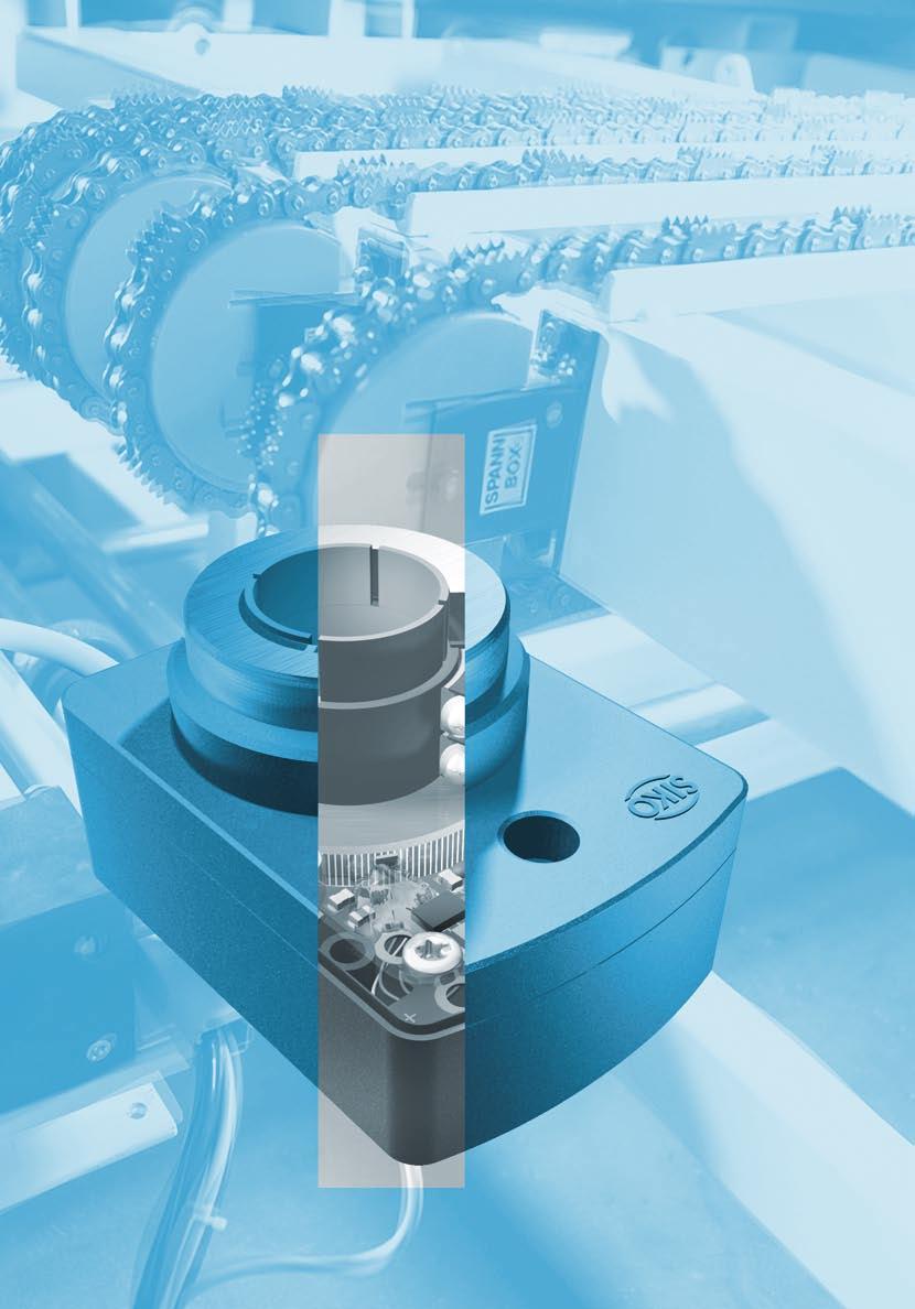
8 8 Magnetic Rotary Encoders General information and areas of application Time for a new generation time for new standards This SIKO development with its indestructible, magnetic scanning technology is suitable for completely new mechanical engineering concepts. oth resolution and scanning reliability as well as the robustness of the compact measuring systems cover application areas which by far exceed those of optical rotary encoders. How it works With a magnetic ring [1] mounted on a hollow or solid shaft, the rotation of machine shafts or spindles can be transmitted to special electronic sensors [2]. The [1] [2] [3] The signal path: A sensor [2] tracks the north-south poles [1] of the specially magnetized ferrite ring and generates pulses [3] which are processed in real time and made available as digital signals. magnetized pole length of the magnetic ring is converted by a customized evaluation electronic system into up to 2,560 pulses per rotation. These incremental counting pulses are available as square wave signals [3] and can therefore be evaluated by any electronic counting system. Sealing of the electronic components also permits safe operation, even with fluid media. The magnetic absolute measurement requires an even more cunning use of the technology, as the possible shaft adjustment is also logged when the system is not supplied with power. Therefore on a magnetic angle encoder, an initial dimetral magnet installed upstream from the functional logic system described above generates a complete sinus signal per rotation. This already absolute single turn signal is also digitized and offset with the sequence signal. enefits Very high shock, vibration and temperature resistance Fully resistant to oil, lubricants, dirt and water Wear and maintenance-free sensor system Optional sealing of the electronics also permits use in oil baths etc. Very compact designs Magnetic encoders are very versatile due to the wide range of versions for hollow shaft and solid shaft installation Magnetic ring with magnetized north and south poles Digital output signal Sensor with downstream real-time processing 2 RotoLine Magnetic rotary encoders


 As well as in all applications where precision measurement is required under extremely difficult conditions 2 3 4 [1] Die for")
9 9 Application areas 1 Magnetic encoders were developed for wet or humid and heavily soiled operating conditions and where machine vibrations make precise operation difficult. These non-contacting measuring encoders almost always feel at home even if they are in contact with corrosive solutions such as saline water or in heated, oily environments. In the food, packaging, energy generation and wood processing sectors or for passenger transport and general mechanical engineering applications, optical measuring systems increasingly reach insurmountable limits due to their basic functional design. For this reason magnetic encoders are predestined for a large number of different applications Sheet metal processing with punching and forming equipment Lifting and elevator equipment In offshore plants Packaging and food industries Chemical and pharmaceutical industries Energy generation (e. g., wind generators) As well as in all applications where precision measurement is required under extremely difficult conditions [1] Die for metal processing [2] Cutting in the wood, metal and stone processing industry. [3] Tire balancing system. [4] Elevator equipment. [5] Rough wood processing: SIKO magnetic encoders are not affected by pronounced vibration or shocks, a greasy environment or coarse or fine dust, either wet or dry, and they also withstand extreme temperature fluctuations. 5 2 RotoLine Magnetic rotary encoders


10 10 Magnetic Rotary Encoders Function and application Ambient conditions Examples of use enefits Moisture Insensitive to moisture, as the scanning process does not require direct visibility. No mounting arrangements or moisture protection necessary e.g., metal saws, food production, portal-type car wash facilities, stoneworking Knocks and vibration Unshakeable: The components employed are indestructible, the glass required in optical encoders is not necessary, all components are safely integrated. High level of reliability High level of operational reliability e.g., presses and dies, construction vehicles, elevators, rough wood processing Climatic fluctuations Absolutely safe function if condensation forms due to fast changes in temperature or icing of components in free-standing installations. High level of operational safety Maintenance-free e.g., cranes, forklifts, wind power plants, ski-lifts Soiling Encapsulated housing and scanning without contact or visibility protects the units against penetrating particles. High level of operational safety No additional protection measures necessary e.g., wood processing, construction machines, tunnel advance, filling systems 2 RotoLine Magnetic rotary encoders
11 Magnetic Rotary Encoders Product matrix 11 Magnetic rotary encoders IH28M IV28M IH58M IV58M IG04M IG07M IG09M WH58M WV58M Page Measurement type Incremental Absolute single-turn Shaft design Hollow shaft Solid shaft Shaft diameters 8 mm 5, 6 mm 6 22 mm 6, 8, 10 mm 10, 14 mm 20 mm mm mm 6, 10 mm Output circuits PP OP LD5 LD24 SSI CAN bus Profibus Housings Plastic Zinc die-cast Aluminum Steel Resolutions Max. pulses/revolution RotoLine Magnetic rotary encoders
 cylindrical 11 27.")
12 12 Magnetic incremental encoder IH28M Small design with through hollow shaft Profile Small design, Ø 28 mm Resolutions of max pulses/revolution Hollow shafts up to Ø 8 mm, stainless steel IP54 protection category Housing made of aluminum and plastic A before cable sleeve (recomm.) cylindrical type of pin connection E1 ø3 DIN 7 type of connection E6X H max fit length 23 ca. grub screw M3 DIN 916 L cable length L cable length ~ 18.5 Mechanical data Feature Technical data Additional information Max. speed 3000 rpm Shaft moment of inertia ~0.24 x 10⁻⁶ kgm 2 Starting torque 0.1 Ncm at 20 C Weight ~0.1 kg Protection category IP54 Operating temperature C Storage temperature C Shock resistance 200 g/6 ms according to DIN EN Vibration resistance 10 g/50 Hz according to DIN EN Shaft stainless steel, 8 mm Housing aluminum and plastic Cable sheath PUR Ø 4.8 mm 2 RotoLine Magnetic rotary encoders
13 Magnetic incremental encoder IH28M Small design with through hollow shaft 13 Electrical data Output circuit Feature PP, OP Push-pull LD5 Line driver LD24 Line driver Additional information Operating voltage V DC +5 V DC ±5 % V DC Power consumpt. w/o load (typ.) <25 ma <25 ma <25 ma A0 variant Maximum load/channel ±30 ma ±30 ma ±30 ma Max. pulse frequency 100 khz 100 khz 100 khz Phasing Signal level high (min.) 29.2 V DC U = 30 V, I OH = -30 ma Signal level low (max.) 0.5 V DC U = 30 V, I OL = 30 ma Signal level RS422 A spec. RS422 A spec. Inverse-polarity protection on U yes no yes Signal image A /A / O I A 0 The state of the signals A and with regard to the reference signal 0 is not defined and can deviate from the signal image. Pin assignment Output circuit PP Signal E1 E6X white 1 +U brown 2 0/I green 3 A yellow 4 GND gray 5 N.C. 6-7 Output circuit OP, LD5, LD24 Signal E1 E6X / blue A N.C. 0 green C /0 red D A yellow E /A pink F N.C. G white H N.C. J GND gray K N.C. L +U brown M PP (Push-pull) LD5 (Line driver) +U A,,0 GND +U A,,0 /A,/,I GND OP (Push-pull, complementary) 5V 24V +U A,,0 /A,/,I GND LD24 (Line driver, 24 V DC supply) +U A,,0 /A,/,I GND 2 RotoLine Magnetic rotary encoders
14 14 Magnetic incremental encoder IH28M Small design with through hollow shaft Order Order table Feature Order data Specification Additional information Output signals A0, AI, AX Pulses/revolution 50, 200, 250, 300, 400, 500, 800, 1000 others on request Order code IH28M 8 A C D E A Type of connection E1 flying leads E6X connector Cable length L (m) 0.3, 1, 2,, 3, 4, 5, 8, 10 Output circuit PP push-pull OP push-pull with inverted signals LD5 line driver LD24 line driver C D E Scope of delivery: IH28M, User information Accessories: Mating connectors Page 88 Cable extension Page 90 Electronic displays MA55, MA10/4 Catalog 6 DisplayLine Additional information: General information and areas of application Page 8 cont. Subject to technical alterations 10/ RotoLine Magnetic rotary encoders

15 Magnetic incremental encoder IV28M/1 Small design with solid shaft 15 Profile Small design, Ø 28 mm Resolutions of max pulses/revolution Solid shafts up to Ø 6 mm, stainless steel IP54 protection category Plastic housing h7 d 10 2 ~35 position of electrical connection A * min.installation space (once-only bend) position of electrical connection R A before 28 ø, 8 deep (for M3) ~42* ca. 47 type of connection E1 type of connection E6X ~ ca cable lengthl cable length L Mechanical data Feature Technical data Additional information Max. speed 3000 rpm Shaft moment of inertia ~0.24 x 10⁻⁶ kgm 2 Starting torque 0.1 Ncm at 20 C Shaft load rating radial 30 N axial 8 N Weight ~0.1 kg Protection category IP54 Operating temperature C Storage temperature C Shock resistance 200 g/6 ms according to DIN EN Vibration resistance 10 g/50 Hz according to DIN EN Shaft stainless steel Housing plastic Cable sheath PUR Ø 4.8 mm 2 RotoLine Magnetic rotary encoders
16 16 Magnetic incremental encoder IV28M/1 Small design with solid shaft Electrical data Output circuit Feature PP, OP Push-pull LD5 Line driver LD24 Line driver Additional information Operating voltage V DC +5 V DC ±5 % V DC Current consumpt. w/o load (typ.) <25 ma <25 ma <25 ma A0 variant Maximum load/channel ±30 ma ±30 ma ±30 ma Max. pulse frequency 100 khz 100 khz 100 khz Phasing Signal level high (min.) 29.2 V DC U = 30 V, I OH = -30 ma Signal level low (max.) 0.5 V DC U = 30 V, I OL = 30 ma Signal level RS422 A spec. RS422 A spec. Inverse-polarity protection on U yes no yes Signal image A /A / O I A 0 The state of the signals A and with regard to the reference signal 0 is not defined and can deviate from the signal image. Pin assignment Output circuit PP Signal E1 E6X white 1 +U brown 2 0/I green 3 A yellow 4 GND gray 5 N.C. 6-7 Output circuit OP, LD5, LD24 Signal E1 E6X / blue A N.C. 0 green C /0 red D A yellow E /A pink F N.C. G white H N.C. J GND gray K N.C. L +U brown M PP (Push-pull) LD5 (Line driver) +U A,,0 GND +U A,,0 /A,/,I GND OP (Push-pull, complementary) 5V 24V +U A,,0 /A,/,I GND LD24 (Line driver, 24 V DC supply) +U A,,0 /A,/,I GND 2 RotoLine Magnetic rotary encoders
17 Magnetic incremental encoder IV28M/1 Small design with solid shaft 17 Order Order table Feature Order data Specification Additional information Output signals A0, AI, AX Pulses/revolution 36, 50, 200, 250, 400, 500, 800, 1000 others on request A Type of connection E1 flying leads E6X connector Position of the electrical connection A R C D E F G axial radial Cable length L (m) 0.07, 0.3, 0.35, 1, 2,, 3, 4, 5, 8, 10 Output circuit PP push-pull OP push-pull with inverted signals LD5 line driver LD24 line driver Shaft diameter 5x10 Ø 5 mm, length 10 mm 6x10 Ø 6 mm, length 10 mm, bush glued on Order code IV28M/1 A C D E F G Subject to technical alterations 03/2009 Scope of delivery: IV28/1, User information Accessories: Mating connectors Page 88 Cable extension Page 90 Electronic displays MA55, MA10/4 Catalog 6 DisplayLine Additional information: General information and areas of application Page 8 cont. 2 RotoLine Magnetic rotary encoders

18 18 Magnetic incremental encoder IH58M Aluminum housing with through hollow shaft Profile Resolutions of max pulses/revolution Hollow shafts up to Ø 22 mm, stainless steel Protection category IP65 Aluminum housing Condensation permitted with sealed electronics unit shaft design grub screw GW 5.5 L recommended installation grub screw GW measureød measureød1 measurel <= > clamping ring KL 2x grub screw M4 d1 H7 d d max. ø cylindrical pin ø4x20 DIN 7 (in the accessories pack) shaft design L clamping ring KL x grub screw M4 measureød measureød1 measure L <= > d1 H7 max. ø22 A before 58 A before body of machine L cable length type of connection E1V 0.5 min ± ± type of connectione2 cylindrical pin ø4x20 DIN 7 (in the accessories pack) Mechanical data Feature Technical data Additional information Max. speed 6000 rpm Shaft moment of inertia ~0.3 x 10⁻⁶ kgm 2 Starting torque 4 Ncm at 20 C Weight ~0.4 kg Protection category IP65 Operating temperature C Storage temperature C Shock resistance 200 g/6 ms according to DIN EN Vibration resistance 10 g/50 Hz according to DIN EN Shaft stainless steel Housing aluminum Cable sheath PUR Ø 4.8 mm 2 RotoLine Magnetic rotary encoders
19 Magnetic incremental encoder IH58M Aluminum housing with through hollow shaft 19 Electrical data Output circuit Feature PP, OP Push-pull LD5 Line driver LD24 Line driver Additional information Operating voltage V DC +5 V DC ±5 % V DC Current consumpt. w/o load (typ.) <25 ma <25 ma <25 ma A0 variant Maximum load/channel ±30 ma ±30 ma ±30 ma Max. pulse frequency 100 khz 100 khz 100 khz Phasing 90 ±15 90 ±15 90 ±15 Signal level high (min.) 29.2 V DC U = 30 V, I OH = -30 ma Signal level low (max.) 0.5 V DC U = 30 V, I OL = 30 ma Signal level RS422 A spec. RS422 A spec. Inverse-polarity protection on U yes no yes Signal image 180 ±30 A /A / O I A 0 90 ± ± /-50 Pin assignment Output circuit PP Signal E1V E2 N.C. 1 N.C. 2 0/I green 3 N.C. 4 A yellow 5 N.C. 6 N.C. 7 white 8 N.C. 9 GND gray 10 N.C. 11 +U brown 12 Output circuit LD5 Signal E1V E2 / blue 1 +SU violet 2 0 green 3 /0 red 4 A yellow 5 /A pink 6 N.C. 7 white 8 N.C. 9 GND gray 10 SGND black 11 +U brown 12 Output circuit OP, LD24 Signal E1V E2 / blue 1 N.C. 2 0 green 3 /0 red 4 A yellow 5 /A pink 6 N.C. 7 white 8 N.C. 9 GND gray 10 N.C. 11 +U brown 12 PP (Push-pull) LD5 (Line driver) +U A,,0 GND +SU +U A,,0 /A,/,I OP (Push-pull, complementary) 5V 24V +U A,,0 /A,/,I GND LD24 (Line driver, 24 V DC supply) +U A,,0 /A,/,I GND SGND GND 2 RotoLine Magnetic rotary encoders
20 20 Magnetic incremental encoder IH58M Aluminum housing with through hollow shaft Order Order table Feature Order data Specification Additional information Output signals A0, AI, AX Pulses/revolution 50, 64, 100, 128, 200, 250, 256, 320, 400, 500, 512, 640, 800, 1000, 1024, 1280, 1600, 2000, 2048, 2560 others on request Order code IH58M A C A Type of connection E1V PG screwing E2 connector C D Cable length L (m) 0.2, 0.3, 0.5, 1, 2, 3, 4, 5, 6, 7, 8, 10, 20 OK without cable only with E2 Output circuit PP push-pull OP push-pull with inverted signals LD5 line driver LD24 line driver Shaft design GW set screw KL clamp ring Shaft diameter 6, 7, 8, 9.525, 10, 12, 14, 15, , 16, 18, 19, 19.05, 20, 22 Ambient condition S condensation not permitted E condensation permitted E F G H D E F G H Scope of delivery: IH58M, User information Accessories: Mating connectors Page 88 Cable extension Page 90 Electronic displays MA55, MA10/4 Catalog 6 DisplayLine Additional information: General information and areas of application Page 8 cont. Subject to technical alterations 03/ RotoLine Magnetic rotary encoders
21 Magnetic incremental encoder IV58M Aluminum housing with solid shaft 21 Profile Resolutions of max pulses/revolution Solid shafts up to Ø 10 mm, stainless steel IP65 protection category Aluminum housing Condensation permitted with sealed electronics unit mounting type M1 g A before M4 x 6 deep (3x120 ) 58 f7 36 d Meas. ød Meas. L L mounting type M2 L cable length L h7 50 g6 d M4 x 6 (3x120 ) 13.5 type of connection E1V 13.5 type of connection E Mechanical data Feature Technical data Additional information Max. speed 6000 rpm Shaft moment of inertia ~0.15 x 10⁻⁶ kgm 2 Starting torque 1.5 Ncm at 20 C Shaft load rating radial 80 N axial 40 N Weight ~0.4 kg Protection category IP65 Operating temperature C Storage temperature C Shock resistance 200 g/6 ms according to DIN EN Vibration resistance 10 g/50 Hz according to DIN EN Shaft stainless steel Housing aluminum Cable sheath PUR Ø 4.8 mm 2 RotoLine Magnetic rotary encoders
22 22 Magnetic incremental encoder IV58M Aluminum housing with solid shaft Electrical data Output circuit Feature PP, OP Push-pull LD5 Line driver LD24 Line driver Additional information Operating voltage V DC +5 V DC ±5 % V DC Current consumpt. w/o load (typ.) <25 ma <25 ma <25 ma A0 variant Maximum load/channel ±30 ma ±30 ma ±30 ma Max. pulse frequency 100 khz 100 khz 100 khz Phasing 90 ±15 90 ±15 90 ±15 Signal level high (min.) 29.2 V DC U = 30 V, I OH = -30 ma Signal level low (max.) 0.5 V DC U = 30 V, I OL = 30 ma Signal level RS422 A spec. RS422 A spec. Inverse-polarity protection on U yes no yes Signal image 180 ±30 A /A / O I A 0 90 ± ± /-50 Pin assignment Output circuit PP Signal E1V E2 N.C. 1 N.C. 2 0/I green 3 N.C. 4 A yellow 5 N.C. 6 N.C. 7 white 8 N.C. 9 GND gray 10 N.C. 11 +U brown 12 Output circuit LD5 Signal E1V E2 / blue 1 +SU violet 2 0 green 3 /0 red 4 A yellow 5 /A pink 6 N.C. 7 white 8 N.C. 9 GND gray 10 SGND black 11 +U brown 12 Output circuit OP, LD24 Signal E1V E2 / blue 1 N.C. 2 0 green 3 /0 red 4 A yellow 5 /A pink 6 N.C. 7 white 8 N.C. 9 GND gray 10 N.C. 11 +U brown 12 PP (Push-pull) LD5 (Line driver) +U A,,0 GND +SU +U A,,0 /A,/,I OP (Push-pull, complementary) 5V 24V +U A,,0 /A,/,I GND LD24 (Line driver, 24 V DC supply) +U A,,0 /A,/,I GND SGND GND 2 RotoLine Magnetic rotary encoders
23 Magnetic incremental encoder IV58M Aluminum housing with solid shaft 23 Order Order table Feature Order data Specification Additional information Output signals A0, AI, AX Pulses/revolution 50, 64, 100, 128, 200, 250, 256, 320, 400, 500, 512, 640, 800, 1000, 1024, 1280, 1600, 2000, 2048, 2560 others on request Order code IV58M A C A Type of connection E1V PG screwing E2 connector C D Cable length L (m) 1, 2, 3, 4, 5, 7, 8, 10, 15, 20 OK without cable only with E2 Mounting type M1 clamping flange M2 servo-flange Output circuit PP push-pull OP push-pull with inverted signals LD5 line driver LD24 line driver Shaft diameter 6x10 Ø 6 mm, length 10 mm 8x10 Ø 8 mm, length 10 mm 10x20 Ø 10 mm, length 20 mm Ambient condition S condensation not permitted E condensation permitted E F G H D E F G H Scope of delivery: IV58M, User information Subject to technical alterations 03/2009 Accessories: Mating connectors Page 88 Cable extension Page 90 Self-aligning coupling Page 94 Servo-clamp Page 95 Electronic displays MA55, MA10/4 Catalog 6 DisplayLine Additional information: General information and areas of application Page 8 cont. 2 RotoLine Magnetic rotary encoders
, IP63 (ball bearing) Housing made of reinforced plastic 9 10 fit length 5 torque pin form A form 5 9 h9 6 intermediate")
24 24 Incremental encoder IG04M Flat design with through hollow shaft Profile Installation depth 25 mm Resolutions of max pulses/revolution Through hollow shafts up to max. Ø 14 mm with plain or ball bearing IP50 protection category (plain bearing), IP63 (ball bearing) Housing made of reinforced plastic 9 10 fit length 5 torque pin form A form 5 9 h9 6 intermediate plate A before grub screw M torque pin H7 d 21* * * only with slide bearing 14 cable lengthl cable lengthl ~61 type of connectione1 type of connection E6X Mechanical data Feature Technical data Additional information Max. speed plain bearing 600 rpm short-time ball bearing 3000 rpm Shaft moment of inertia ~1.9 x 10⁻⁶ kgm 2 Weight ~0.1 kg with 1 m cable Protection category IP50 plain bearing IP63 ball bearing Operating temperature C Storage temperature C Shock resistance 200 g/6 ms according to DIN EN Vibration resistance 10 g/50 Hz according to DIN EN Shaft browned steel Housing reinforced plastic Cable sheath PUR Ø 4.8 mm 2 RotoLine Magnetic rotary encoders
25 Incremental encoder IG04M Flat design with through hollow shaft 25 Electrical data Output circuit Feature PP, OP Push-pull LD5 Line driver LD24 Line driver Additional information Output circuit PP, OP push-pull LD5 line driver LD24 line driver Operating voltage V DC +5 V DC ±5 % V DC Current consumpt. w/o load (typ.) <25 ma <25 ma <25 ma A0 variant Maximum load/channel ±30 ma ±30 ma ±30 ma Max. pulse frequency 100 khz 100 khz 100 khz Phasing Signal level high (min.) 29.2 V DC U = 30 V, I OH = -30 ma Signal level low (max.) 0.5 V DC U = 30 V, I OL = 30 ma Signal level RS422 A spec. RS422 A spec. Inverse-polarity protection on U yes no yes Signal image A /A A The state of the signals A and with regard to the reference signal 0 is not defined and can deviate from the signal image. / O I 0 Pin assignment Output circuit PP Signal E1 E6X white 1 +U brown 2 0/I green 3 A yellow 4 GND gray 5 N.C. 67 PP (Push-pull) +U A,,0 GND OP (Push-pull, complementary) +U A,,0 /A,/,I GND Output circuit OP, LD5, LD24 Signal E1 E6X / blue A N.C. 0 green C /0 red D A yellow E /A pink F N.C. G white H N.C. J GND gray K N.C. L +U brown M LD5 (Line driver) +U A,,0 /A,/,I GND LD24 (Line driver, 24 V DC supply) 5V 24V +U A,,0 /A,/,I GND 2 RotoLine Magnetic rotary encoders
26 26 Incremental encoder IG04M Flat design with through hollow shaft Order Order table Feature Order data Specification Additional information Output signals A0, AI, AX Order code IG04M A Pulses/revolution 50, 100,200, 300, 400, 500, 600, 700, 800, 900, 1000, 1100, 1200, 1300, 1400, 1500, 1600, 1700, 1800, 1900, 2000 others on request Type of connection E1 flying leads E6X connector Cable length L (m) 0.5, 1.0,, 3.0, 4.0, 5.0, 6.0, 7.0, 8.0, 9.0, 10.0, 11.0, 1, 13.0, 14.0, 15.0, 16.0, 17.0, 18.0, 19.0, 20.0 Output circuit PP push-pull OP push-pull with inverted signals LD5 line driver LD24 line driver Shaft diameter G14 plain bearing Ø 14 mm K10 ball bearing Ø 10 mm Torque support A form A, cylindric pin form, for tolerance compensation Intermediate plate OZP without intermediate plate ZP with intermediate plate C D E F G H LO A C D E F G H Scope of delivery: IG04M, User information Accessories: Mating connectors Page 88 Cable extension Page 90 Electronic displays MA55, MA10/4 Catalog 6 DisplayLine Additional information: General information and areas of application Page 8 cont. Subject to technical alterations 03/ RotoLine Magnetic rotary encoders

27 Incremental encoder IG07M Robust housing made of zinc die-cast with through hollow shaft 27 Profile Resolutions of max pulses/revolution High shaft load rating, axial 1400 N; radial 5600 N Through hollow shafts up to Ø 20 mm, stainless steel IP64 protection category Housing made of zinc die-cast Condensation permitted with sealed electronics unit cable lengthl ca x grub screw M4 A before 6 H8 M H7 d max. ø H7 d max. ø20 37 ± x grub screw M4 40 ± type of connection E1 type of connection EX shaft design grub screw GW shaft design clamping ring KL Mechanical data Feature Technical data Additional information Max. speed 6000 rpm, IP rpm, IP65 Shaft moment of inertia ~0.3 x 10⁻⁶ kgm 2 Starting torque 6 Ncm, IP64 at 20 C 10 Ncm, IP65 Shaft load rating radial 5600 N axial 1400 N Weight ~0.75 kg Protection category IP64, high-precision packed sealing gap IP65, enhanced bearing sealing Operating temperature C Storage temperature C Shock resistance 200 g/6 ms according to DIN EN Vibration resistance 10 g/50 Hz according to DIN EN Shaft stainless steel, Ø 20 mm Housing zinc die-cast Cable sheath PUR Ø 4.8 mm 2 RotoLine Magnetic rotary encoders
28 28 Incremental encoder IG07M Robust housing made of zinc die-cast with through hollow shaft Electrical data Output circuit Feature PP, OP Push-pull LD5 Line driver LD24 Line driver Additional information Operating voltage V DC +5 V DC ±5 % V DC Current consumpt. w/o load (typ.) <25 ma <25 ma <25 ma A0 variant Maximum load/channel ±30 ma ±30 ma ±30 ma Max. pulse frequency 100 khz 100 khz 100 khz Phasing 90 ±15 90 ±15 90 ±15 Signal level high (min.) 29.2 V DC U = 30 V, I OH = -30 ma Signal level low (max.) 0.5 V DC U = 30 V, I OL = 30 ma Signal level RS422 A spec. RS422 A spec. Inverse-polarity protection on U yes no yes Signal image 180 ±30 A /A / O I A 0 90 ± ± /-50 Pin assignment Output circuit PP Signal E1 EX N.C. A N.C. 0/I green C N.C. D A yellow E N.C. F N.C. G white H N.C. J GND gray K N.C. L +U brown M Output circuit LD5 Signal E1 E6X / blue A +SU violet 0 green C /0 red D A yellow E /A pink F N.C. G white H N.C. J GND gray K SGND black L +U brown M Output circuit OP, LD24 Signal E1 E6X / blue A N.C. 0 green C /0 red D A yellow E /A pink F N.C. G white H N.C. J GND gray K N.C. L +U brown M PP (Push-pull) LD5 (Line driver) +U A,,0 GND +SU +U A,,0 /A,/,I OP (Push-pull, complementary) LD24 (Line driver, 24 V DC supply) 5V 24V +U A,,0 /A,/,I GND +U A,,0 /A,/,I GND SGND GND 2 RotoLine Magnetic rotary encoders
29 Incremental encoder IG07M Robust housing made of zinc die-cast with through hollow shaft 29 Order Order table Feature Order data Specification Additional information Output signals A0, AI, AX Pulses/revolution 50, 64, 100, 200, 250, 256, 320, 400, 512, 640, 800, 900, 1000, 1024, 1280, 1600, 2000, 2048, 2560 others on request Order code A Type of connection E1 flying leads EX connector C D Cable length L (m) 01.0, 0, 03.0, 04.0, 05.0, 08.0, 10 OK without cable only with EX Output circuit PP push-pull OP push-pull with inverted signals LD5 line driver LD24 line driver Shaft design GW set screw KL clamp ring earing MS IP64, high-precision packed sealing gap RS IP65, enhanced bearing sealing Ambient condition S condensation not permitted E condensation permitted E F G H IG07M 20 M1 A C D E F G H Subject to technical alterations 03/2009 Scope of delivery: IG07M, User information Accessories: Mating connectors Page 88 Cable extension Page 90 Electronic displays MA55, MA10/4 Catalog 6 DisplayLine Additional information: General information and areas of application Page 8 cont. 2 RotoLine Magnetic rotary encoders

30 30 Incremental encoder IG09M Flat design with through hollow shaft Profile Resolutions of max pulses/revolution Through hollow shafts up to Ø 20 mm IP53 and IP63 protection categories Housing made of reinforced plastic Condensation permitted with sealed electronics unit Can be combined with the DA09S position indicator 5 shaft design grub screw GW 2x grub screw M d d H7 max. ø torque pin form A 9 6 h9 30 ±0.1 form intermediate plate torque pin type of connection E6X ~ ± ca. 15 type of connection E1 35 H7 max. ø A vor shaft design clamping ringkl 2x grub screw M4 50 cable length L cable length L Mechanical data Feature Technical data Additional information Max. speed plain bearing 6000 rpm Shaft moment of inertia ~0.15 x 10⁻⁶ kgm 2 Starting torque 2 Ncm, IP53 at 20 C 3.5 Ncm, IP63 Weight ~0.12 kg Protection category IP53 IP63 Operating temperature C Storage temperature C Shock resistance 200 g/6 ms according to DIN EN Vibration resistance 10 g/50 Hz according to DIN EN Shaft browned steel Housing reinforced plastic Cable sheath PUR Ø 4.8 mm 2 RotoLine Magnetic rotary encoders
31 Incremental encoder IG09M Flat design with through hollow shaft 31 Electrical data Output circuit Feature PP, OP Push-pull LD5 Line driver LD24 Line driver Additional information Operating voltage V DC +5 V DC ±5 % V DC Current consumpt. w/o load (typ.) <25 ma <25 ma <25 ma A0 variant Maximum load/channel ±30 ma ±30 ma ±30 ma Max. pulse frequency 100 khz 100 khz 100 khz Phasing 90 ±15 90 ±15 90 ±15 Signal level high (min.) 29.2 V DC U = 30 V, I OH = -30 ma Signal level low (max.) 0.5 V DC U = 30 V, I OL = 30 ma Signal level RS422 A spec. RS422 A spec. Inverse-polarity protection on U yes no yes Signal image 180 ±30 A /A / O I A 0 90 ± ± /-50 Pin assignment Output circuit PP Signal E1 E6X N.C. A N.C. 0/I green C N.C. D A yellow E N.C. F N.C. G white H N.C. J GND gray K N.C. L +U brown M Output circuit OP, LD5, LD24 Signal E1 E6X / blue A N.C. 0 green C /0 red D A yellow E /A pink F N.C. G white H N.C. J GND gray K N.C. L +U brown M PP (Push-pull) LD5 (Line driver) +U A,,0 GND +U A,,0 /A,/,I GND OP (Push-pull, complementary) LD24 (Line driver, 24 V DC supply) 5V 24V +U A,,0 /A,/,I GND +U A,,0 /A,/,I GND 2 RotoLine Magnetic rotary encoders
32 32 Incremental encoder IG09M Flat design with through hollow shaft Order Order table Feature Order data Specification Additional information Output signals A0, AI, AX Pulses/revolution 50, 64, 100, 128, 200, 250, 256, 320, 400, 512, 640, 800, 1000, 1024, 1280, 1600, 2000, 2048, 2560 others on request A Type of connection E1 flying leads E6X connector Cable length L (m) 0.3, 0.4, 1, 2, 3, 4, 5, 6, 7, 8, 10, 11, 12, 15, 20 Output circuit PP push-pull OP push-pull with inverted signals LD5 line driver LD24 line driver C D Shaft design GW set screw KL clamp ring E F G H Shaft diameter 12, 14, 15, 16, 20 Ambient condition S condensation not permitted E condensation permitted I K L Torque support A form A, cylindric pin form, for tolerance compensation Protection category IP53 IP63 Intermediate plate OZP without intermediate plate ZP with intermediate plate Order code IG09M A C D E F G H I K L Scope of delivery: IG09M, User information Accessories: Mating connectors Page 88 Cable extension Page 90 Electronic displays MA55, MA10/4 Catalog 6 DisplayLine Additional information: General information and areas of application Page 8 cont. Subject to technical alterations 03/ RotoLine Magnetic rotary encoders

33 Angle encoder WH58M Metal housing with through hollow shaft 33 Profile Very compact design Hollow shafts up to max. Ø 22 mm Robust contactless scanning 12 bit, single-turn Standard: SSI output; RS485 and fieldbus as options Hood made of sheet steel shaft design grub screw GW 2x grub screw M4 25 H7 d max. ø xgrub screw M4 37 shaft design clamping ring KL H7 d max. ø ±0.8 E sense of rotation I cylindrical pin ø4x20 DIN 7 (in accessories pack) type of connection E2 5 ±2 33 fit length 55.5 locking screw for setting the addresses or parameter, resp. type of connection E4 5.5 type of connectione12 (screw thread M12) US-IN (pin) supply US-OUT (bushing) Mechanical data Feature Technical data Additional information Max. speed 6000 rpm Shaft moment of inertia ~17 x 10-6 kgm 2 Starting torque 0.03 Nm at 20 C Weight ~0.4 kg Protection category IP65 Operating temperature C Storage temperature C Shock resistance 200 g/6 ms according to DIN EN Vibration resistance 10 g/5 150 Hz according to DIN EN Shaft stainless steel Housing aluminum and steel 2 RotoLine Magnetic rotary encoders
34 34 Angle encoder WH58M Metal housing with through hollow shaft Electrical data Feature Additional information Protocol SIKONETZ-3 SSI CAN bus Profibus P CANopen Operating voltage V DC V DC V DC V DC Output driver interface RS485 RS422 CAN high-speed RS485 acc. to ISO/DIS Current consumption ~0.4 W ~0.9 W <1.1 W <1.1 W without load (typical) SSI clock rate min. 65 khz (<400 m cable length) max. 1 MHz (<25 m cable length) aud rate (kbit/s) , 250, 500, , 19.2, 93.75, 187.5, 500, 1500, 3000, 6000, Short-circuit resistant outputs yes yes yes yes output against output or output against GND in case of short circuit Inverse-polarity protection on U yes yes yes yes External calibration input no yes no no Pin configuration Connector pin assignment E2; SSI interface Signal PIN GND 1 +U 2 Clock + 3 Clock - 4 Data + 5 Data - 6 RS485 DÜA 10 RS485 DÜ 12 N.C. 79, 11 Connector pin assignment E2; SSI interface with external calibration input Signal PIN GND 1 +U 2 Clock + 3 Clock - 4 Data + 5 Data - 6 External calibration input 8 RS485 DÜA 10 RS485 DÜ 12 N.C. 7, 9, 11 Connector pin assignment E12; Profibus interface Signal Signal PIN Profibus-IN Profibus-OUT N.C. VP (2P5) 1 US-A US-A 2 N.C. DGND (2M) 3 US- US- 4 N.C. screen 5 Connector pin assignment E12; interface CAN bus Signal Signal PIN CANopen-IN CANopen-OUT N.C. N.C. 1 N.C. N.C. 2 CAN_GND CAN_GND 3 CAN_H CAN_H 4 CAN_L CAN_L 5 Connector pin assignment E12; power supply Power supply PIN +U 1 N.C. 2 GND 3 N.C. 4 Connector pin assignment E4; SIKONETZ-3 interface Signal PIN DÜA 1 DÜ 2 GND 3 N.C. 4 +U 5 N.C RotoLine Magnetic rotary encoders
35 Angle encoder WH58M Metal housing with through hollow shaft 35 Order Order table Feature Order text Specification Additional information Interface/protocol CAN CAN bus CANopen P A Profibus DP S3/06 SIKONETZ-3 RS485 S6/04 SSI RS422 S6/04-K SSI with external calibration input RS422 Type of connection E2 connector for SSI E4 connector for SIKONETZ-3 E12 connector for CAN bus or Profibus Steps per revolution bit bit C D Shaft design GW set screw only with hollow shaft Ø 14 mm KL clamp ring only with hollow shaft Ø 20 mm Hollow shaft/diameter 14, 20 others on request Ambient condition S condensation not permitted E condensation permitted E F Order code WH58M 1 A C D E F Subject to technical alterations 03/2009 Scope of delivery: WH58M, User information Accessories: Mating connectors Page 88 Cable extension Page 90 Electronic displays MA55, MA10/4 Catalog 6 DisplayLine Additional information: General information and areas of application Page 8 cont. 2 RotoLine Magnetic rotary encoders
36 36 Angle encoder WV58M Metal housing with solid shaft Profile Very compact design Robust contactless scanning 12 bit, single-turn Standard: SSI output; RS485 and fieldbus as options Hood made of sheet steel measure ød measure L E sense of rotation I M4 x 6 deep (3x120 ) 42 type of connection E d g h7 50 L 50 type of connection E4 locking screw for setting the addresses or parameter, resp type of connection E12 (screw thread M12) US-IN (pin) supply US-OUT (bushing) Mechanical data Feature Technical data Additional information Max. speed 6000 rpm Shaft moment of inertia ~5 x 10⁻⁶ kgm 2 Starting torque 0.01 Nm at 20 C Shaft load rating radial 80 N axial 40 N Weight ~0.4 kg Protection category IP65 Operating temperature C Storage temperature C Shock resistance 200 g/6 ms according to DIN EN Vibration resistance 10 g/5 150 Hz according to DIN EN Shaft stainless steel Housing aluminum and steel 2 RotoLine Magnetic rotary encoders
37 Angle encoder WV58M Metal housing with solid shaft 37 Electrical data Feature Additional information Protocol SIKONETZ-3 SSI CAN bus Profibus P CANopen Operating voltage V DC V DC V DC V DC Output driver interface RS485 RS422 CAN high-speed RS485 acc. to ISO/DIS Current consumption ~0.4 W ~0.9 W <1.1 W <1.1 W without load (typical) SSI clock rate min. 65 khz (<400 m cable length) max. 1 MHz (<25 m cable length) aud rate (kbit/s) , 250, 500, , 19.2, 93.75, 187.5, 500, 1500, 3000, 6000, Short-circuit resistant outputs yes yes yes yes output against output or output against GND in case of short circuit Inverse-polarity protection on U yes yes yes yes External calibration input no yes no no Pin assignment Connector pin assignment E2; SSI interface Signal PIN GND 1 +U 2 Clock + 3 Clock - 4 Data + 5 Data - 6 RS485 DÜA 10 RS485 DÜ 12 N.C. 79, 11 Connector pin assignment E2; SSI interface with external calibration input Signal PIN GND 1 +U 2 Clock + 3 Clock - 4 Data + 5 Data - 6 External calibration input 8 RS485 DÜA 10 RS485 DÜ 12 N.C. 7, 9, 11 Connector pin assignment E12; Profibus interface Signal Signal PIN Profibus-IN Profibus-OUT N.C. VP (2P5) 1 US-A US-A 2 N.C. DGND (2M) 3 US- US- 4 N.C. screen 5 Connector pin assignment E12; Can bus interface Signal Signal PIN CANopen-IN CANopen-OUT N.C. N.C. 1 N.C. N.C. 2 CAN_GND CAN_GND 3 CAN_H CAN_H 4 CAN_L CAN_L 5 Connector pin assignment E12; Power supply Power supply PIN +U 1 N.C. 2 GND 3 N.C. 4 Connector pin assignment E4; SIKONETZ-3 interface Signal PIN DÜA 1 DÜ 2 GND 3 N.C. 4 +U 5 N.C RotoLine Magnetic rotary encoders
38 38 Angle encoder WV58M Metal housing with solid shaft Order Order table Feature Order text Specification Additional information Interface/protocol CAN CAN bus CANopen P A Profibus DP S3/06 SIKONETZ-3 RS485 S6/04 SSI RS422 S6/04-K SSI with external calibration input RS422 Type of connection E2 connector for SSI E4 connector for SIKONETZ-3 E12 connector for CAN bus or Profibus Steps per revolution bit bit Shaft/diameter x length 6x10 Ø 6 mm, length 10 mm 10x20 Ø 10 mm, length 20 mm Ambient condition S condensation not permitted E condensation permitted C D E Order code WV58M 1 A C D E Scope of delivery: WV58M, User information Accessories: Mating connectors Page 88 Cable extension Page 90 Self-aligning coupling Page 94 Servo-clamp Page 95 Electronic displays MA55, MA10/4 Catalog 6 DisplayLine Additional information: General information and areas of application Page 8 cont. Subject to technical alterations 03/ RotoLine Magnetic rotary encoders
39 39 2 RotoLine Magnetic rotary encoders

40
41 Optical rotary encoders Table of contents 41 RotoLine Product Overview 3 Magnetic rotary encoders 6 Optical rotary encoders General information and areas of application 42 Function and application 44 Product matrix 45 Products Incremental encoders IG06 46 IG07 49 IG17 53 Angle encoders WK50/1 57 Geared potentiometers 60 Accessories 86 Product index, Contact information 96 2 RotoLine Optical rotary encoders

42 42 Optical rotary encoders General information and areas of application Sophisticated technology for high-resolution applications Optical encoders have an excellent cost-benefit ratio. This fully developed technology offers robust and well-sealed housings, permitting reliable measurement with very high resolutions in a large number of industrial applications. Signal sequences are generated, which form the basis for calculating the respective rotation angle. Combined with an intelligent follow-up electronic system, reliable calculation of angles, lengths and even speeds is possible. The core of optical encoder technology is precisely segmented code discs with patterns in a circular arrangement. Well protected against external influences, the transparent and opaque sections alternate at defined intervals, dividing a beam of light directed onto a sensor into digital yes and no counting units. As two signal sequences A and, offset by 90, are scanned with each rotation, the electronic system also detects the clockwise/counter-clockwise direction of rotation due to the phase offset, with the advantage of enhancing the mechanical and electrical safety and reliability of the system. The hollow shaft incremental encoders are simply slipped onto the shaft or spindle. Solid shaft encoders are mounted with a flange and a connecting coupling. The absolute, opto-electronic scanning principle using an angle encoder as an example Incremental encoders During incremental processes, an optoelectronic scanning unit tracks the uniform-incremental dividing pattern of the code disc and converts these into a number of electronic pulses that is proportional to the rotation. In the event of a voltage drop, however, the measured value is lost the incremental encoder requires a reference operation. The opto-electronic scanning unit (here in the IG06) converts light pulses into digital signals. Light module High resolutions, a clever housing concept, functional overall design with simple slip-on mounting and locking: The optical SIKO encoders are excellently equipped for demanding measuring assignments Code disc with incremental or absolute patterns (light transparency) 2 RotoLine Optical rotary encoders

.")
, it is also possible to track very long linear paths with a fine resolution.")

43 43 Angle encoders Absolute encoders or angle encoders measure angles absolutely and directly. Linear motion can also be tracked if this is converted to a rotating motion by toothed belts, drive wheels or cables. The absolute encoding disc has transparent or opaque encoding on several tracks. As a result the measured values can be tracked absolutely and are also still available after power interruptions without a reference operation. The range includes single turn versions for repeated single rotations and multiturn versions for absolute multiple rotation Single turn permits up to 8192 measuring steps/rotation (13 bits). Encoding starts again at the initial value after each full rotation. Multi-turn is performed in the same manner as single turn, but permits 4096 rotations with an encoded reduction gear (12 bits). Due to the very high number of measuring steps (> 33 million, 12 bits plus 13 bits = 25 bits), it is also possible to track very long linear paths with a fine resolution. Applications Optical encoders are the right choice when it comes to applications with very high resolution requirements. Angle encoders are, for example, particularly suitable for applications in the wood, metal, printing and packaging industries. The devices tirelessly track the complex and highly dynamic motion of robot arms and do not require maintenance. They perform excellently on linear shafts, during angle adjustment operations and monitoring synchronized operations. These encoders are reliable and offer a quick return on investment due to their track-proven specifications. Even load limits determined by the measuring principle can be almost completely eliminated by effective installation on the machine [1] Paper dust and precision monitoring printing speed, roller alignment and setting of paper formats. [2] Dynamics and resolution cooperating robots during the deflectometric inspection of a bodywork section (photo: indigo werbefotografie Fraunhofer Institute for Information and Data Processing IIT 2008, Chair for interactive real-time systems at the University of Karlsruhe, TH). [3] High air humidity food production Handtmann Maschinenfabrik GmbH & Co. KG, [4] Shavings, high mechanical loads cutting and surface processing in the wood industry. 2 RotoLine Optical rotary encoders
, drilling systems, foil production Tracking paths (running and extension length, distance, stops, etc.")


44 44 Optical rotary encoders Function and application Ambient conditions Examples of use enefits Tracking the number of revolutions or speed The high mechanical load capacity permits applications which require a constantly reliable long-term function. Variable diameter Can be installed in any position High mechanical load capacity e.g., turning techniques (lathes), drilling systems, foil production Tracking paths (running and extension length, distance, stops, etc.) Reliable incremental or absolute path measurement: Robust housings encapsulate the high-resolution encoders, guarantee precise measuring results on a large and small scale. Simple installation Robust components e.g., run length control, storage technology, elevators for material, packing and cutting Tracking of spindle adjustment (angle and positioning measurement) High repeat accuracy with exact positioning the optical SIKO encoders are designed for demanding operations. Very high resolution Precise positioning e.g., dowel drilling units and surface refinement in the furniture industry, industrial robotics Application with compound and rotary tables, material testing, forming technology or Access control 2 RotoLine Optical rotary encoders
45 Optical rotary encoders Product matrix 45 Optical rotary encoders IG06 IG07 IG17 WK50/1 Page Measurement type Incremental Absolute multi-turn Shaft design Hollow shaft Solid shaft Shaft diameter mm mm 6 16 mm 16, 20 mm Output circuit PP OC OP LD5 LD24 SSI Housing Plastic Zinc die-cast Aluminum Resolution Max. pulses/revolution Max. number of revolutions RotoLine Optical rotary encoders
46 46 Incremental encoder IG06 Sturdy plastic housing with through hollow shaft Profile Resolutions of max pulses/revolution Through hollow shafts up to Ø 20 mm Housing made of impact-resistant plastic Low-cost version ±0.1 ± A vor ± mounting type M1 M4 (2x120 ) H H ± mounting type M ± ± H8 d M3x 6 deep (2x) M4 (2x120 ) 17 H8 d shaft design W type of connectione type of connection E1 E6 + cable lengthl2 E6 50 cable length L E6X shaft design W02 9 shaft design W ~ 61 cable length L2 ~61 cable length L 2 RotoLine Optical rotary encoders
47 Incremental encoder IG06 Sturdy plastic housing with through hollow shaft 47 Mechanical data Electrical data Feature Technical data Additional information Max. speed 6000 rpm 600 rpm with W02, W04 with W01, W01N Shaft moment of inertia ~10.5 x 10⁻⁶ kgm 2 ~9.5 x 10⁻⁶ kgm 2 ~9 x 10⁻⁶ kgm 2 with W01, W01N with W02 with W04 Starting torque at 20 C 15 Ncm, with W Ncm, with W02 and W04 Shaft load rating radial 20 N axial 10 N radial 50 N axial 25N with W01 with W01 with W02, W04 with W02, W04 Weight ~0.14 kg Protection category IP54 Operating temperature C Storage temperature C Shock resistance 200 g/6 ms according to DIN EN Vibration resistance 10 g/50 Hz according to DIN EN Shaft browned steel Housing reinforced plastic Cable sheath PVC or PUR Output circuit Feature PP Push-pull OC (NPN) Open collector Additional information Operating voltage V DC V DC Current consumpt. w/o load (typ.) <50 ma <50 ma A0 variant Maximum load/channel ±40 ma, short circuit-resistant ±50 ma Max. pulse frequency 25 khz 25 khz Phasing 90 ±30 90 ±30 Signal level high (min.) U -2 V, at 20 ma wiring-dependent Signal level low (max.) 1 V, at 20 ma 0.1 V DC Inverse-polarity protection on U yes yes Signal image A /A A 180 ±30 90 ±30 / 360 ± 40 O I /-50 Pin assignment Output circuit PP, OC Signal E1 E6X, E6 GND gray 1 A yellow 2 white 3 0/I green 4 +U brown 5 N.C. 6, 7 PP (Push-pull) +U A,,0 GND OC Open Collector, NPN-type +U A,,0 GND 2 RotoLine Optical rotary encoders
48 48 Incremental encoder IG06 Sturdy plastic housing with through hollow shaft Order Maximum pulses with output signals Output signal Plain bearing W01 all bearing, W02, W04 AXX AX A AI The max. permissible pulses/ revs. must not be exceeded by the output signals. Order table Feature Order text Specification Additional information Output signals AXX, AX, A0, AI A Pulses/revolution 1, 2, 5, 10, 20, 25, 36, 40, 50, 60, 70, 80, 90, 100, 125, 140, 150, 180, 200, 220, 240, 250, 280, 300, 360, 400, 500, 600, 1000, 1024 others on request Cable sheath PUR oil-resistant PVC Type of connection E1 flying leads E6 cable coupler with cable extension E6X cable coupler C D E Cable length L 0.3, 2 40 m, in steps of 1 m only PVC 0.3, 2, 3 only PUR F Cable length L2 0.3, 2 15 m, in steps of 1 m only PVC 0.3, 2, 3 only PUR Mounting type M1 with blind hole bore M2 with mounting plate G H Output circuit PP push-pull OC open collector Shaft design W01 set screw/plain bearing W02 clamp ring/ball bearing W04 set screw/ball bearing I K Hollow shaft/diameter (mm) 20 Ø 20 mm with W01 14, 15 mm with W02 10, 12 mm with W04 Order code IG06 A C D E F G H I K Scope of delivery: IG06, User information Accessories: Electronic displays MA55, MA10/4 Additional information: General information and areas of application Catalog 6 DisplayLine Page 42 cont. Subject to technical alterations 03/ RotoLine Optical rotary encoders
49 Incremental encoder IG07 Housing made of zinc die-cast with through hollow shaft 49 Profile Resolutions of max pulses/revolution Through hollow shafts up to Ø 20 mm Housing made of zinc die-cast High shaft load rating: radial 5600 N, axial 1400 N (EX+E3+E4) (E1) shaft design W01 grub screw 2x M4 mounting type M1 58 A before 90 mounting type M2 40 H8 H ± M fit length 40 ± ± shaft design W fit length 14 H ca. 20 L cable length 40 ca. ~ 54 E3 + cable length L E cable length E4 + cable length L E4 50 L cable length ca type of connection EX type of connection E1 20 type of connection E type of connection E RotoLine Optical rotary encoders
50 50 Incremental encoder IG07 Housing made of zinc die-cast with through hollow shaft Mechanical data Electrical data Feature Technical data Additional information Max. speed 6000 rpm 3000 rpm with IP64 with IP65 Shaft moment of inertia ~28.5 x 10⁻⁶ kgm 2 ~58.5 x 10⁻⁶ kgm 2 ~35.5 x 10⁻⁶ kgm 2 with W01 with W02 with W03 Starting torque at 20 C 6 Ncm 10 Ncm with IP64 with IP65 Shaft load rating radial 5600 N axial 1400 N Weight ~0.75 kg Protection category IP64, IP65 Operating temperature C Storage temperature C Shock resistance 200 g/6 ms according to DIN EN Vibration resistance 10 g/50 Hz according to DIN EN Shaft browned steel Housing zinc, die-cast Cable sheath PVC Output circuit Feature PP, OP Push-pull LD Line driver LD24 Line driver Additional information Operating voltage V DC +5 V DC ±5 % V DC Current consumpt. w/o load (typ.) <40 ma <40 ma <40 ma A0 variant Maximum load/channel ±40 ma, short circuit-resist. ±40 ma, short circuit-resist. ±40 ma, short circuit-resist. Max. pulse frequency 80 khz 50 khz 50 khz Phasing 90 ±30 90 ±30 90 ±30 Signal level high (min.) U -2 V Signal level low (max.) 1 V, at 40 ma Signal level RS422 A spec. RS422 A spec. Inverse-polarity protection on U yes no no Signal image A /A A 180 ±30 90 ±30 / 360 ± 40 O I /-50 2 RotoLine Optical rotary encoders
51 Incremental encoder IG07 Housing made of zinc die-cast with through hollow shaft 51 Pin assignment Output circuit PP Output signals AXX, AX0, AX, A0 Signal E1 EX, E3, E4 GND gray 1 A yellow 2 white 3 0/I green 4 +U brown 5 N.C. 6, 7 PP (Push-pull) +U A,,0 GND OP (Push-pull) +U A,,0 /A,/,I GND Output circuit OP Output signals AXX, AX0, AX Signal E1 EX, E3, E4 GND gray 1 A yellow 2 white 3 N.C. 4 +U brown 5 /A pink 6 / blue 7 Output circuit OP Output signals A0 Signal E1 EX, E3, E4 A yellow A white 0 green C /A pink D / blue E I violet F GND gray G GND black H +U brown J +U red K N.C. L, M LD5 Line driver, differential +SU +U A,,0 /A,/,I GND SGND LD24 OP Line driver, differential +U A,,0 /A,/,I GND Output circuit LD, LD24 Output signals AXX, AX0, AX, A0 Signal E1 EX, E3, E4 A yellow A /A green GND gray C +U pink D white E / brown F +SU red G only with LD5 SGND blue H only with LD5 0 red-blue J I gray-pink K GND black L +U violet M 2 RotoLine Optical rotary encoders
52 52 Incremental encoder IG07 Housing made of zinc die-cast with through hollow shaft Order Order table Feature Order text Specification Additional information Output signals AXX, AX, A0, AI, AX0, AXI Order code A Pulses/revolution 1, 2, 5, 10, 20, 25, 30, 36, 40, 50, 60, 70, 80, 90, 100, 125, 140, 150, 160, 180, 200, 220, 250, 280, 300, 350, 360, 400, 450, 500, 512, 585, 600, 750, 800, 900, 1000, 1024 others on request Type of connection EX without cable E1 flying leads E3 angle plug E4 connector Cable length L 0.5, 2 50 m, in steps of 1 m OK without cable Mounting type M1 with blind hole bore M2 with flange Output circuit PP push-pull OP push-pull with inverted signals LD line driver LD24 line driver, 24 V C D E F G Shaft design/diameter W01 Ø 20 mm ball bearing and clamping screw W01/RH12 with reducing bush Ø 12 mm ball bearing and clamping screw W01/RH14 with reducing bush Ø 14 mm ball bearing and clamping screw W01/RH15 with reducing bush Ø 15 mm ball bearing and clamping screw W01/RH16 with reducing bush Ø 16 mm ball bearing and clamping screw W02 Ø 20 mm ball bearing und clamp ring W02N Ø 20 mm, stainless steel ball bearing und clamp ring earing MS high-precision packed sealing gap, IP64 RS enhanced bearing sealing, IP65 H IG07 SV SG A C D E F G H Scope of delivery: IG07, User information Accessories: Electronic displays MA55, MA10/4 Additional information: General information and areas of application Catalog 6 DisplayLine Page 42 cont. Subject to technical alterations 03/ RotoLine Optical rotary encoders
53 Incremental encoder IG17 Housing made of zinc die-cast with solid shaft 53 Profile Resolutions of max pulses/revolution Solid shafts up to Ø 16 mm Housing made of zinc die-cast High shaft load rating, radial 5600 N, axial 1400 N 89 mounting type M1 58 A before ± (EX, E3, E4) (E1) g6 18 mounting type M3 (IP64) M4 (IP65) M6 (3x120 ) 60 ± ± M4 6 shaft design W f ca. 20 L cable length ca. 40 ~54 E3 18 E3 + cable length L 50 cable length L E4 + cable length L E4 50 cable length L ca type of connection EX type of connection E1 type of connection E3... type of connection E RotoLine Optical rotary encoders
54 54 Incremental encoder IG17 Housing made of zinc die-cast with solid shaft Mechanical data Feature Technical data Additional information Max. speed 6000 rpm 3000 rpm with IP64 with IP65 Shaft moment of inertia ~28.5 x 10⁻⁶ kgm 2 with W01 Starting torque at 20 C 6 Ncm 10 Ncm with IP64 with IP65 Shaft load rating radial 5600 N axial 1400 N Weight ~0.75 kg Protection category IP64, IP65 Operating temperature C Storage temperature C Shock resistance 200 g/6 ms according to DIN EN Vibration resistance 20 g/ Hz according to DIN EN Shaft browned steel Housing zinc, die-cast Cable sheath PVC Electrical data Output circuit Feature PP, OP Push-pull LD Line driver LD24 Line driver Additional information Operating voltage V DC +5 V DC ±5 % V DC Current consumpt. w/o load (typ.) <40 ma <40 ma <40 ma A0 variant Maximum load/channel ±40 ma, short circuit-resist. ±40 ma, short circuit-resist. ±40 ma, short circuit-resist. Max. pulse frequency 80 khz 50 khz 50 khz Phasing 90 ±30 90 ±30 90 ±30 Signal level high (min.) U -2 V Signal level low (max.) 1 V, at 40 ma Signal level RS422 A spec. RS422 A spec. Inverse-polarity protection on U yes no no Signal image A /A / O I A ±30 90 ± ± /-50 2 RotoLine Optical rotary encoders
55 Incremental encoder IG17 Housing made of zinc die-cast with solid shaft 55 Pin assignment Output circuit PP Output signals AXX, AX0, AX, A0 Signal E1 EX, E3, E4 GND gray 1 A yellow 2 white 3 0/I green 4 +U brown 5 N.C. 6, 7 PP (Push-pull) +U A,,0 GND OP (Push-pull) +U A,,0 /A,/,I GND Output circuit OP Output signals AXX, AX0, AX Signal E1 EX, E3, E4 GND gray 1 A yellow 2 white 3 N.C. 4 +U brown 5 /A pink 6 / blue 7 Output circuit OP Output signals A0 Signal E1 EX, E3, E4 A yellow A white 0 green C /A pink D / blue E I violet F GND gray G GND black H +U brown J +U red K N.C. L, M LD5 Line driver, differential +SU +U A,,0 /A,/,I GND SGND LD24 OP Line driver, differential +U A,,0 /A,/,I GND Output circuit LD, LD24 Output signals AXX, AX0, AX, A0 Signal E1 EX, E3, E4 A yellow A /A green GND gray C +U pink D white E / brown F +SU red G only with LD5 SGND blue H only with LD5 0 red-blue J I gray-pink K GND black L +U violet M 2 RotoLine Optical rotary encoders
56 56 Incremental encoder IG17 Housing made of zinc die-cast with solid shaft Order Order table Feature Order text Specification Additional information Output signals AXX, AX, A0, AI, AX0, AXI Order code A Pulses/revolution 1, 2, 5, 10, 20, 25, 30, 36, 40, 50, 60, 70, 80, 90, 100, 125, 140, 150, 160, 180, 200, 220, 250, 280, 300, 350, 360, 400, 450, 500, 512, 585, 600, 750, 800, 900, 1000, 1024 others on request Type of connection EX without cable E1 flying leads E3 angle plug E4 connector Cable length L 0.5, 2 60 m, in steps of 1 m OK without cable C D E Mounting type M 1 with blind hole bore 3 with flange, IP64 only with MS 4 with flange, IP65 only with RS Output circuit PP push-pull OP push-pull with inverted signals LD line driver LD24 line driver, 24 V Shaft diameter 12 Ø 12 mm others on request earing MS high-precision packed sealing gap, IP64 RS enhanced bearing sealing, IP65 F G H IG17 W01 SG A C D E F G H Scope of delivery: IG17, User information Accessories: Servo-clamp Page 95 Electronic displays MA55, MA10/4 Catalog 6 DisplayLine Additional information: General information and areas of application Page 42 cont. Subject to technical alterations 03/ RotoLine Optical rotary encoders
57 Angle encoder WK50/1 Metal housing with through hollow shaft 57 Profile Up to 8192 steps per revolution and 4096 revolutions SSI interface Gray or binary output code Programmable Through hollow shaft E sense of rotation I 4x M5, 10 deep 19 max ± H7 40 f torque pin form A ± Z type of connection E2 X cable length L 50 shaft design H h9 type of connection E2 ca E2 E2 + cable length L 2 RotoLine Optical rotary encoders
58 58 Angle encoder WK50/1 Metal housing with through hollow shaft Mechanical data Electrical data Pin assignment Feature Technical data Additional information Accuracy ±1 LS Max. speed 3000 rpm 2000 rpm with IP54 with IP65 Shaft moment of inertia ~1 x 10⁻⁴ kgm2 Angular acceleration 2 x 10⁵ rad/s2 Starting torque at 20 C ~5 Ncm ~15 Ncm with IP54 with IP65 Shaft load rating radial 1200 N axial 400 N Weight ~1.2 kg Protection category IP64, IP65 Operating temperature C Storage temperature C earing life min. 400 x 106 revolutions 109 with 20 N shaft load Shock resistance 30 g/13 ms according to DIN EN Vibration resistance 10 g/5 150 Hz, 20 g/ Hz according to DIN EN Shaft browned steel, on double ball bearing Housing aluminum Cable sheath PVC Electrical data SSI Additional information Operating voltage 24 V DC ±20 % Output driver RS 485 Power consumption <1.3 W Permissible load/channel max. 1 MHz SSI clock rate min./max. 100 khz/500 khz Signal level high typ. 3.8 V Signal level low typ. 1.3 V (20 ma) Ramp up time tr max. 100 ns without cable Ramp down time tf max. 100 ns without cable Short-circuit resistant outputs yes, short-circuit to GND permissible Inverse-polarity protection on U Type of connection E2, E2X Interface S6/04, SSI yes Signal Cable color PIN Data- pink 1 Data+ blue 2 Clock - red 3 Clock+ black 4 +U (Power supply) brown 5 GND (Interface) white 6 DÜA (Interface) yellow 7 DÜ (Interface) green 8 GND (Power supply) gray 9 2 RotoLine Optical rotary encoders
59 Angle encoder WK50/1 Metal housing with through hollow shaft 59 Order Order table Feature Order text Specification Additional information Interface/protocol S6/04 RS422/SSI clock rate depending on cable length 100 khz 1 MHz Inter-us-S and Profibus on request A Type of connection E2 with mating connectors for SSI E2X without mating connectors for SSI C Cable length L 0.5, 2 20 m, in steps of 1 m only with E1, E2, E6 OK without cable D Steps per revolution 256, 360, 512, 720, 1024, 2048, 4096, 8192 max. 13 bit E Number of revolutions 128, 256, 512, 1024, 2048, 4096 max. 12 bit Output code binary code G Gray code F G H Sense of rotation E counter-clockwise ascending values I clockwise ascending values Protection category IP 54 IP54 65 IP65 Torque support/form A form A, cylindric pin O without torque support I K Shaft diameter 16 Ø 16 mm 20 Ø 20 mm Order code WK50/1 A C D E F G H I M1 H2 K Subject to technical alterations 03/2009 Scope of delivery: WK50/1, User information Accessories: Servo-clamp Page 95 Electronic displays MA55, MA10/4 Catalog 6 DisplayLine Additional information: General information and areas of application Page 42 cont. 2 RotoLine Optical rotary encoders

60
61 Geared potentiometers Table of contents 61 RotoLine Product Overview 3 Magnetic rotary encoders 6 Optical rotary encoders 40 Geared potentiometers General information and areas of application 62 Technical details 64 Function and application 66 Product matrix 67 Products GP02 68 GP03/1 71 GP04/1 74 GP09 77 GP43 80 GP44 83 Accessories 86 Product index, Contact information 96 2 RotoLine Geared potentiometers


62 62 Geared potentiometers General information and areas of application Robust analog units for absolute length and angle measurement Geared potentiometers are used for absolute measurement of angles and lengths. Adjustment motions which are performed without operating voltage are automatically tracked by the position of the wiper and forwarded to the measurement indicator or controller when the power supply is restored. Referencing for determining the position is not necessary. This mature and track-proven geared potentiometer measuring method, also referred to as GP, registers rotation and makes this available for length and angle definition. A combination of gear unit and potentiometer tracks rotation and forwards the information to the follow-up evaluators (such as indicators, controllers) as analog signals (potentiometers, current, voltage). A large number of ratios and analog outputs are available and enable optimum adaptation to the required measuring ranges. Gear unit for gear reduction of rotary motion Optional integrated converters permit loss-free signal transmission, even over long line lengths. A useful additional effect: Cable breaks can be automatically displayed as status information, which enables simple programming of emergency stop operations. An integrated cam controller is available for the models GP43 and GP44, which can also control switching operations at the same time as absolute measurement when equipped with up to three switches. Geared potentiometers are also suitable for rough environments. For example, the GP09 is also available as an oil-filled version and permits absolute measurement in applications with protection category IP68. Switch cam with configurable switching patterns The devices can be inconspicuously integrated into the machine configuration. The compact and dust-tight housings are connected to the machine shaft with hollow shaft or solid shaft installation. A friction clutch (all types except GP02) prevents mechanical damage of the GP unit when the end stops are exceeded. enefits Long service life resulting from consistent further development Optimized dimensions: High performance in a compact housing Absolute tracking directly on the machine shaft rotation Versatile analog signal on the encoder output Robust housing versions Easy integration due to hollow and solid shaft design Numerous gear ratios for optimum adaptation to the customer s measuring range Unit with switch cam and potentiometer Functional principle of geared potentiometers absolute and reliable: Equipped with analog intelligence, geared potentiometers work with an electromagnetic memory. 2 RotoLine Geared potentiometers


![[2] Moisture, shavings and vibration rough wood cutting in sawmills.](/docs-images/77/75357320/images/63-4.jpg "[3] Changing weather conditions passenger boarding bridge at Dresden airport, (photo: Weimer Flughafen Dresden GmbH).")
63 Areas of application A large number of designs and variable technical features open up a wide range of applications for the robust geared potentiometers. The simple installation of the hollow shaft versions also ensures short setup times and simple retrofitting. SIKO encoders are used during the initial stage of cutting tree trunks in the wood industry, because they can withstand the high mechanical stresses in this environment. Accuracy and reliability are also advantages of the SIKO encoders in the conveying technology and automation sectors. Together with geared potentiometers, they are also indispensable in the paper and printing industry. Here they are used in multi-color printing presses for register adjustment to ensure exact alignment of the rollers. 4 3 [1] Temperature fluctuations and a high humidity horizontal/vertical position control of water cannons for firefighting. [2] Moisture, shavings and vibration rough wood cutting in sawmills. [3] Changing weather conditions passenger boarding bridge at Dresden airport, (photo: Weimer Flughafen Dresden GmbH). [4] Fine dust, precision roller alignment, contact pressure/speed control and fine adjustment for paper infeed for newspaper and magazine printing, adischer Verlag & Co. KG, Freiburg. [5] Direct installation motor feedback on a roller unit (paper industry). 5 2 RotoLine Geared potentiometers

64 64 Geared potentiometers Technical details Gear ratio calculation Due to the variety of different gear ratios and the use of 1-coil or 10-coil potentiometers, all measuring ranges can be covered individually. The minimum ratio is calculated with the following formula. The selection of the gear ratio depends on the maximum measurement path, i.e., the total number of rotations. A friction clutch between the gear unit and potentiometer (on all except GP02) prevents the mechanical destruction of the potentiometer. Example A measuring path of n = 500 rotations is achieved by the use of a 10-coil potentiometer and a gear ratio of i = 50 (refer to formula). Formula: 1 = n x 360 a n = number of revolutions on the driving shaft a = potentiometer angle of rotation 340 with 1-coil potentiometer 3600 with 10-coil potentiometer i1 = order feature for gear ratios Note 1-coil potentiometers have a measuring range of 340 and do not have a mechanical stop (type 01). 10-coil potentiometers cover a measuring range of 3600 and are equipped with a mechanical stop (type 02/03). 10-coil potentiometers are protected against mechanical destruction by a friction clutch (type 02/03). Drive and gear i1 cam mechanism i2 = 10 to 10-coil potentiometer 1 to 1-coil potentiometer potentiometer switch Available ratios The available ratios are shown for the individual products in the ordering table. Other ratios, also intermediate values, are available upon request. A C drive shaft cam slipping clutch Fine adjustment of the cam discs is performed with the screw gear. The time for a switching pulse can therefore be determined individually and precisely. 2 RotoLine Geared potentiometers
65 65 Switching cam function diagram GP43 and GP44 are available with up to three cam switches to control additional switching operations. Switching angle Cam switches are available in three different switching angle versions (refer to table). Types 1, 2 and 3 are standard products for various control functions. Individual switching angles are possible upon request. Cam form/switching angle Type Actuating angle Special technical features 1 ~ 16 end position limitation 2 ~ 80 control functions 3 ~ 196 control functions 10 Typ Especially for end position limitation For control functions Fine adjustment Switching angle of the three switching cams Interfaces With a transducer the SIKO geared potentiometers are available with various analog outputs: Potentiometer output 0 1 kω, 0 5 kω and 0 10 kω Without transducer... kω Pe S Po Current output All GPs are also optionally available with a ma transducer. When ordering always state the direction of rotation code, either i or e. Advantage: Long line lengths are possible and cable breaks are detected immediately. Transducer MWI ducer MWI 10 kω I+ I- Voltage output A stable voltage of V is output via an external power supply depending on the potentiometer setting. Transducer MWU R/I-transducer +U 10 kω U out GND R/U-transducer Transducer adjustment On the potentiometers with transducers the measurement path can be modified with so-called trimming potentiometers. Transducer MWI The potentiometer resistance is converted into a current of ma (standard value). These values can be adapted to the actual beginning and end settings of the application with two trimming potentiometers Po and Pe. Transducer MWU The potentiometer resistance is converted into a voltage of V DC. With a trimming potentiometer Pe the end value can be adapted to the actual end position of the application. 2 RotoLine Geared potentiometers


66 66 Geared potentiometers Function and application Ambient conditions Examples of use enefits Level and distance measurement Acts directly via the shaft or spindle. The principle of operation corresponds to that of a wire-actuated encoder. Easy mounting Delay-free reaction time Absolute measurement e.g., mobile derrick jibs, warehousing/forklift technologies, level measurement... Path measurement Acts indirectly (offset) on toothed racks via cogwheel or worm gear. Various shaft diameters Variable mounting positions e.g., door locking, dowel drilling machines... Position measurement Acts directly via the shaft or spindle. Suitable gear reductions or ratios enable very high fine resolution. Precise position monitoring Variable attachment diameters (hollow/solid shaft) Angle measurement e.g., edge glueing or grinding technologies... Acts directly (offset). Safe absolute measurement since currentless adjustment is recorded. Exact angle indication Variable mounting positions Solid electromechanical design and construction for tough industrial environments e.g., textile-/foil production, building crane technology, fire-fighting cannons Or hoisting and conveying 2 RotoLine Geared potentiometers
67 Geared potentiometers Product matrix 67 Geared potentiometers GP02 GP03/1 GP04/1 GP09 GP43 GP44 Page Shaft design Hollow shaft Solid shaft Shaft diameter 14 mm 6 mm 16, 20 mm 20 mm 6 mm 16, 20 mm Analog outputs Potentiometer Power output Voltage output Housing Plastic Plastic reinforced Aluminum Zinc die-cast Protection category IP52 IP65 IP68 Switching cam Friction clutch 2 RotoLine Geared potentiometers

68 68 Geared potentiometer GP02 Compact design with through hollow shaft Profile Through hollow shaft Ø 14 mm Adaptation to various measurement paths owing to a wide range of gear ratios Compact, low-cost design Potentiometer or power output Easy mounting i sense of rotation 14 e fit depth M3, 4x90 turned 14 H form torque pin form A h9 Mechanical data Feature Technical data Additional information Gear ratio Speed max. 500 rpm depending on gear ratio Operating temperature C Condensation inadmissible Service life of axial movement 1 x x 10 6 with P01, P02 with P03 Protection category IP52 according to DIN VDE 0470 Shaft browned steel, Ø 14 mm Housing plastic 2 RotoLine Geared potentiometers
69 Geared potentiometer GP02 Compact design with through hollow shaft 69 Electrical data Feature Technical data Additional information Interference protection class 3 according to IEC 801 Analog outputs Feature Technical data Voltage supply Potentiometer output 0 1 kω, 0 5 kω, 0 10 kω depending on the potentiometer type used Power output 4 20 ma 24 V DC ±20 %, with load 500 Ω Potentiometer type Feature /0.1 Design hybrid wire hybrid Resistance 1 kω, 5 kω, 10 kω 1 kω, 5 kω, 10 kω 1 kω, 5 kω, 10 kω Resistance tolerance ±5 % ±5 % ±5 % Linearity tolerance ±0.25 % ±0.25 % ±0.1 % Load rating 1 W at 70 C 1 W at 70 C 2 W at 70 C Range of rotation 340 ± ± ±10 (mechanically straight-through) Standard terminal resistor (the higher value is always valid) 0.5 % or 1 Ω 0.5 % or 1 Ω 0.5 % or 1 Ω Note: Characters highlighted in orange color are order features. Pin assignment Potentiometric outputs P01, P05, P10 Signal Po Pe S Transducer MWI Cable color brown white green Signal Cable color I+ brown I- white Potentiometric outputs P01, P05, P10 Pe S... kω Po Transducer MWI I+ 10 kω I- R/I-transducer 2 RotoLine Geared potentiometers
70 70 Geared potentiometer GP02 Compact design with through hollow shaft Order Ratio calculation (order table, feature A) Formula: i1 = n x 360 a n = number of revolutions on the driving shaft a = potentiometer angle of rotation 340 with 1-coil potentiometer 3600 with 10-coil potentiometer i1 = order feature for gear ratio If the calculated ratio i1 is the same as a value in the ordering table for the ratio feature, but this is not available, select the next highest ratio. Order table Feature Order data Specifications Additional information Gear ratio 0.125, 0.2, 0.25, 0.333, 0.5, 1, 2, 3, 4, 5, A 6, 7, 9, 10, 12, 15, 16, 20, , 24, 28, 30, 36, , 48, 55, 68, 80, 112, 128 others on request Torque support A form A, cylindric pin form for tolerance compensation Potentiometer type 01 1 coil, hybrid coils, wire coils, hybrid 03/0,1 10 coils, hybrid, linear tolerance 0.1 C D Resistance P01 resistance 1 kω P05 resistance 5 kω P10 resistance 10 kω Order code E Transducer MWI transducer 4 20 ma only with P10 OMW without F Sense of rotation ODR without indication of sense of rotation with P01, P05 or P10 e counter-clockwise ascending values with MWI i clockwise ascending values with MWI Cable length m in steps of 0.1 m G GP02 A C D E F G H I K L M N Scope of delivery: GP02, User information Accessories: Electronic display MA50 Additional information: General information and areas of application Catalog 6 DisplayLine Page 62 cont. Subject to technical alterations 10/ RotoLine Geared potentiometers

71 Geared potentiometer GP03/1 Compact design with solid shaft 71 Profile Solid shaft Ø 4 mm or Ø 6 mm Adaptation to various measurement paths owing to a wide range of gear ratios Integrated friction clutch to protect the potentiometer Compact design Potentiometer, power or voltage output IP65 protection category 10 e sense of rotation i 4 2 flange 360 rotatable f7 70 g (PG7) 35 (PG9) type of connection E1/7 type of connection E1/ max. allowable shaft load radial 400N axial 150N 18 M12x1 type of connection EX Mechanical data Feature Technical data Additional information Gear ratio Speed max. 500 rpm depending on gear ratio Operating temperature C Condensation inadmissible Service life of axial movement 1 x x 10 6 with P01, P02 with P03 Protection category IP65 according to DIN VDE 0470 Maximum shaft load radial 400 N axial 150 N Shaft stainless steel, Ø 6 mm Housing reinforced plastic and aluminum 2 RotoLine Geared potentiometers
72 72 Geared potentiometer GP03/1 Compact design with solid shaft Electrical data Feature Technical data Additional information Interference protection class 3 according to IEC 801 Analog outputs Feature Technical data Voltage supply Potentiometer output 0 1 kω, 0 5 kω, 0 10 kω depending on the potentiometer type used Power output 4 20 ma 24 V DC ±20 %, with load 500 Ω Voltage output 0 10 V 24 V DC ±20 % Potentiometer type Characteristic/Specification Design hybrid wire hybrid Resistance 1 kω, 5 kω, 10 kω 1 kω, 5 kω, 10 kω 1 kω, 5 kω, 10 kω Resistance tolerance ±5 % ±5 % ±5 % Linearity tolerance ±0.25 % ±0.25 % ±0.25 % Load rating 1 W at 70 C 1 W at 70 C 2 W at 70 C Range of rotation 340 ± ± ±10 (mechanically straight-through) Standard terminal resistor (the higher value is always valid) 0.5 % or 1 Ω 0.5 % or 1 Ω 0.5 % or 1 Ω Note: Characters highlighted in orange color are order features. Pin assignment Potentiometric outputs P01, P05, P10 Signal E1 (Terminal) EX (Connector pin) Po 3 1 Pe 1 2 S 2 3 N.C. 4 Transducer MWI Signal E1 (Terminal) EX (Connector pin) I+ 1 1 I- 2 2 N.C. 3 3 N.C. 4 Potentiometric outputs P01, P05, P10 Pe S... kω Po Transducer MWI Transducer MWU Signal E1 (Terminal) EX (Connector pin) +24 V DC 1 1 GND 2 2 U out 3 3 N.C kω R/I-transducer I+ I- Transducer MWU +U 10 kω U out GND R/U-transducer 2 RotoLine Geared potentiometers
73 Geared potentiometer GP03/1 Compact design with solid shaft 73 Order Ratio calculation (ord er table, feature A) Formula: i1 = n x 360 a n = number of revolutions on the driving shaft a = potentiometer angle of rotation 340 with 1-coil potentiometer 3600 with 10-coil potentiometer i1 = order feature for gear ratio If the calculated ratio i1 is the same as a value in the ordering table for the ratio feature, but this is not available, select the next highest ratio. Order table Feature Order data Specifications Additional information Gear ratio 0.1, 0.166, 0.25, 0.333, 0.5,1, 2, 3, 4, 5, A 6, 7, 10, 12, 15, 20, 24, 30, 40, 55 others on request Type of connection E1/7 screwed cable gland PG7 E1/9 screwed cable gland PG9 EX for M12 connector Potentiometer type 01 1 coil, hybrid coils, wire coils, hybrid C D Analog output MWI transducer 4 20 ma only with P10 MWU transducer 0 10 V only with P10 P01 potentiometer 1 kω P05 potentiometer 5 kω P10 potentiometer 10 kω E Sense of rotation ODR without indication of sense of rotation with P01, P05 or P10 e counter-clockwise ascending values with MWI or MWU i clockwise ascending values with MWI or MWU Order code GP03/1 V/6 A C D E Scope of delivery: GP03/1, User information Accessories: Mating connectors Page 88 Self-aligning coupling Page 94 Electronic display MA50 Catalog 6 DisplayLine Additional information: General information and areas of application Page 62 cont. 2 RotoLine Geared potentiometers
74 74 Geared potentiometer GP04/1 With solid or blind hole shaft Profile Extremely resistant to external influence Solid or blind-hole shaft, max. Ø 20 mm Adaptation to various measurement paths owing to a wide range of gear ratios Integrated friction clutch to protect the potentiometer Potentiometer, power or voltage output IP65 protection category possible e sense of rotation 10 i 15 4 max. allowable shaft load radial 1000N axial 1700N 15 g max. 30 feather key groove DIN 6885/1 H/16 16 H H7 120 V/16 PG Mechanical data Feature Technical data Additional information Gear ratio Speed max. 500 rpm depending on gear ratio Voltage supply 24 VDC ±20 % transducer MWI (with load 500 Ω) Operating temperature C Condensation inadmissible Service life of axial movement 1 x x 10 6 with P01, P02 with P03 Protection category IP52, IP65 according to DIN VDE 0470 Maximum shaft load radial 1000 N, axial 1700 N Shaft aluminum (IP52) browned steel (IP65) Housing aluminum 2 RotoLine Geared potentiometers
75 Geared potentiometer GP04/1 With solid or blind hole shaft 75 Electrical data Feature Technical data Additional information Interference protection class 3 according to IEC 801 Analog outputs Feature Technical data Voltage supply Potentiometer output 0 1 kω, 0 5 kω, 0 10 kω depending on the potentiometer type used Power output 4 20 ma 24 V DC ±20 %, with load 500 Ω Voltage output 0 10 V 24 V DC ±20 % Potentiometer type Characteristic/Specification Design hybrid wire hybrid Resistance 1 kω, 5 kω, 10 kω 1 kω, 5 kω, 10 kω 1 kω, 5 kω, 10 kω Resistance tolerance ±5 % ±5 % ±5 % Linearity tolerance ±0.25 % ±0.25 % ±0.25 % Load rating 1 W at 70 C 1 W at 70 C 2 W at 70 C Range of rotation 340 ± ± ±10 (mechanically straight-through) Standard terminal resistor (the higher value is always valid) 0.5 % or 1 Ω 0.5 % or 1 Ω 0.5 % or 1 Ω Note: Characters highlighted in orange color are order features. Pin assignment Potentiometric outputs P01, P05, P10 Signal Terminal Po 3 Pe 1 S 2 Potentiometric outputs P01, P05, P10 Pe Transducer MWI Signal Terminal I+ 1 I kω S Po Transducer MWU Signal Terminal +24 V DC 1 GND 2 U out 3 Transducer MWI 10 kω I+ I- R/I-transducer Transducer MWU +U 10 kω U out GND R/U-transducer 2 RotoLine Geared potentiometers
76 76 Geared potentiometer GP04/1 With solid or blind hole shaft Order Ratio calculation (ord er table, feature A) Formula: i1 = n x 360 a n = number of revolutions on the driving shaft a = potentiometer angle of rotation 340 with 1-coil potentiometer 3600 with 10-coil potentiometer i1 = order feature for gear ratio If the calculated ratio i1 is the same as a value in the ordering table for the ratio feature, but this is not available, select the next highest ratio. Order table Feature Order data Specifications Additional information Gear ratio 0.1, 0.166, 0.166, 0.25, 0.333, 0.5, 1, 2, A 3, 4, 5, 6, 10, 12, 15, 20, 24, 30, 40, 55 others on request Driving shaft H/20 hollow shaft Ø 20 mm H/16 hollow shaft Ø 16 mm V/20 solid shaft Ø 20 mm V/16 solid shaft Ø 16 mm Order code D GP04/1 A C D E Potentiometer type 01 1 coil, hybrid coils, wire coils, hybrid C Analog output MWI transducer 4 20 ma only with P10 MWU transducer 0 10 V only with P10 P01 potentiometer 1 kω P05 potentiometer 5 kω P10 potentiometer 10 kω E Sense of rotation ODR without indication of sense of rotation with P01, P05 or P10 e counter-clockwise ascending values with MWI or MWU i clockwise ascending values with MWI or MWU Protection category IP52 IP65 F F Scope of delivery: GP04/1, User information Accessories: Electronic display MA50 Additional information: General information and areas of application Catalog 6 DisplayLine Page 62 cont. Subject to technical alterations 10/ RotoLine Geared potentiometers
77 Geared potentiometer GP09 Robust housing with through hollow shaft 77 Profile Resistant to external influences Through hollow shaft Ø 20 mm Adaptation to various measurement paths owing to a wide range of gear ratios Integrated friction clutch to protect the potentiometer Compact design Potentiometer, power or voltage output IP68 protection category with oil filling possible Easy mounting ca. 11 e sense of rotation access trimming potentiometer i torque pin form A form h9 20 H type of connectione1 12 L cable length ca. 55 cable length L type of connection E fit length 46 grub screw 3x M4 Mechanical data Feature Technical data Additional information Gear ratio Speed max. 500 rpm depending on gear ratio Operating temperature C Condensation inadmissible Service life of axial movement 1 x x 10 6 with P01, P02 with P03 Protection category IP52, IP65, IP68 according to DIN VDE 0470 Maximum shaft load radial 400 N axial 150 N Shaft stainless steel, Ø 20 mm Housing zinc die-cast 2 RotoLine Geared potentiometers
78 78 Geared potentiometer GP09 Robust housing with through hollow shaft Electrical data Feature Technical data Additional information Interference protection class 3 according to IEC 801 Analog outputs Feature Technical data Voltage supply Potentiometer output 0 1 kω, 0 5 kω, 0 10 kω depending on the potentiometer type used Power output 4 20 ma 24 V DC ±20 %, with load 500 Ω Voltage output 0 10 V 24 V DC ±20 % Potentiometer type Characteristic/Specification Design hybrid wire hybrid Resistance 1 kω, 5 kω, 10 kω 1 kω, 5 kω, 10 kω 1 kω, 5 kω, 10 kω Resistance tolerance ±5 % ±5 % ±5 % Linearity tolerance ±0.25 ±0.25 % ±0.1 % Load rating 1 W at 70 C 1 W at 70 C 2 W at 70 C Range of rotation 340 ± ± ±10 (mechanically straight-through) Standard terminal resistor (the higher value is always valid) 0.5 % or 1 Ω 0.5 % or 1 Ω 0.5 % or 1 Ω Note: Characters highlighted in orange color are order features. Pin assignment Potentiometric outputs P01, P05, P10 Signal E1 (Cable color) E12 (Connector pin) Po brown 3 Pe white 1 S green 2 N.C. 4 Transducer MWI Signal E1 (Cable color) E12 (Connector pin) I+ brown 3 I- white 1 N.C. 2 N.C. 4 Potentiometric outputs P01, P05, P10 Pe S... kω Po Transducer MWI Transducer MWU Signal E1 (Cable color) E12 (Connector pin) +24 V DC brown 3 GND white 1 U out green 2 N.C kω R/I-transducer I+ I- Transducer MWU +U 10 kω U out GND R/U-transducer 2 RotoLine Geared potentiometers
79 Geared potentiometer GP09 Robust housing with through hollow shaft 79 Order Ratio calculation (order table, feature A) Formula: i1 = n x 360 a n = number of revolutions on the driving shaft a = potentiometer angle of rotation 340 with 1-coil potentiometer 3600 with 10-coil potentiometer i1 = order feature for gear ratio If the calculated ratio i1 is the same as a value in the ordering table for the ratio feature, but this is not available, select the next highest ratio. Order table Feature Order data Specifications Additional information Gear ratio 0.184, 0.27, 0.361, 0.740, 1, 2, 03, A 3.048, 4, 5.213, 6, 8.003, 10, 12, , 20, , , , , , , , others on request Torque support A form A, cylindric pin form for tolerance compensation Potentiometer type 01 1 coil, hybrid coils, wire 03/0,1 10 coils, hybrid, linear tolerance 0.1 C D Analog output MWI transducer 4 20 ma only with P10 MWU transducer 0 10 V only with P10 P01 potentiometer 1 kω P05 potentiometer 5 kω P10 potentiometer 10 kω E Sense of rotation ODR without indication of sense of rotation with P01, P05 or P10 e counter-clockwise ascending values with MWI or MWU i clockwise ascending values with MWI or MWU Type of connection E1 flying leads E12 connector, M12 Cable length L (m) m, in steps of 0.1 m Protection category IP52 IP65 IP68 F G H I with oil filling, against condensation Max. number of revolutions* OAU customer-adjustable except with IP , 0.25, 0.333, 0.6, 1,, 4, 5, only with IP68 prot. categ. and analog output MWI, MWU 10, 12, 20, 24, 40, 60, 75, 100 others on request only with IP68 prot. categ. and analog output MWI, MWU *The max. number of revolutions must be the measuring range. Order code GP09 A C D E F G H I Subject to technical alterations 10/2008 Scope of delivery: GP09, User information Accessories: Mating connectors Page 88 Self-aligning coupling Page 94 Electronic display MA50 Catalog 6 DisplayLine Additional information: General information and areas of application Page 62 cont. 2 RotoLine Geared potentiometers
80 80 Geared potentiometer GP43 Aluminum housing with solid shaft Profile Solid shaft Ø 6 mm Adaptation to various measurement paths owing to a wide range of gear ratios Integrated friction clutch to protect the potentiometer Compact design Potentiometer or power output IP65 protection category possible Up to 3 switching cam outputs, freely adjustable 10 e sense of rotation i 4 2 flange 360 rotatable 4.5 g f PG7 PG9 ca max. allowable shaft load radial 400N axial 150N Mechanical data Feature Technical data Additional information Gear ratio Speed max. 500 rpm depending on gear ratio Operating temperature C with P01, P02 Condensation inadmissible Service life of axial movement 1 x x 10 6 with P03 Protection category IP52, IP65 according to DIN VDE 0470 Maximum shaft load radial 400 N axial 150 N Shaft browned steel, Ø 6 mm Housing aluminum 2 RotoLine Geared potentiometers
81 Geared potentiometer GP43 Aluminum housing with solid shaft 81 Electrical data Feature Technical data Additional information Interference protection class 3 according to IEC 801 Analog outputs Feature Technical data Voltage supply Potentiometer output 0 1 kω, 0 5 kω, 0 10 kω depending on the potentiometer type used Power output 4 20 ma 24 V DC ±20 %, with load 500 Ω Potentiometer type Feature Design hybrid wire hybrid Resistance 1 kω, 5 kω, 10 kω 1 kω, 5 kω, 10 kω 1 kω, 5 kω, 10 kω Resistance tolerance ±5 % ±5 % ±5 % Linearity tolerance ±0.25 % ±0.25 % ±0.25 % Load rating 1 W at 70 C 1 W at 70 C 2 W at 70 C Range of rotation 340 ± ± ±10 (mechanically straight-through) Standard terminal resistor (the higher value is always valid) 0.5 % or 1 Ω 0.5 % or 1 Ω 0.5 % or 1 Ω Note: Characters highlighted in orange color are order features. Pin assignment Potentiometric outputs P01, P05, P10 Signal Terminal Po 11 Pe 13 S 12 Transducer MWI Signal Terminal I+ 12 I- 11 N.C. 13 Switching cam Assignment Switching cam 1 Terminal Switching cam 2 Terminal Switching cam 3 Terminal Potentiometric outputs P01, P05, P10 Pe S... kω Po Transducer MWI 10 kω I+ I- R/I-transducer 2 RotoLine Geared potentiometers
82 82 Geared potentiometer GP43 Aluminum housing with solid shaft Order Ratio calculation (ord er table, feature A) Formula: i1 = n x 360 a n = number of revolutions on the driving shaft a = potentiometer angle of rotation 340 with 1-coil potentiometer 3600 with 10-coil potentiometer i1 = order feature for gear ratio If the calculated ratio i1 is the same as a value in the ordering table for the ratio feature, but this is not available, select the next highest ratio. Switching cam order (example of order table, feature F) Digit 1 Digit 2 Digit 3 Order data cam form 2 2 cam form 1 cam form 3 13 cam form 1 cam form 2 cam form Order table C D E F G Order switching cams! 13 switching cams can be ordered. Therefore, the order element can have 1 to 3 digits. Feature Order data Specifications Additional information Gear ratio 0.1/10, /10, 0.2/10, 0.25/10, 0.333/10, A 0.5/10, 0.5/2,5, 0.8/10, 1, 1.400, 1/3.0357, 2, 4,, 3, 3.333, 4, 5, 5.385, 6, 6.5, 7, 8, 10, 12, 15, 14, 15, 20, 21, 24, 25, 30, 33, 35, 40, 48, 55, 60.5, 64, , 70, 80, 96, 101.5, 121, , 150, 256, 348.8, 384, , 512 others on request Potentiometer type 01 1 coil, hybrid coils, wire coils, hybrid 03/0,1 10 coils, hybrid, linear tolerance ±0,1 % Resistance P01 potentiometer 1 kω P05 potentiometer 5 kω P10 potentiometer 10 kω Transducer MWI transducer 4 20 ma only with P10 OMW without Sense of rotation ODR without indication of sense of rotation with P01, P05 or P10 e counter-clockwise ascending values with MWI i clockwise ascending values with MWI or MWU Switching cam/form 1, 2, 3, 11, 12, 13, 22, 23, 33, 111, 112, 113, 122, 123, 221, 222, 223, 233, 331, 333 others on request Operating voltage of switching cam 1 above 48 V dielectric strength 2 up to 48 V dielectric strength Typ Switching angle of the 3 switching cams: specifically for end position limiter (1), for control functions (2, 3). Order code GP43 A C D E F G Scope of delivery: GP43, User information Accessories: Self-aligning coupling Page 94 Electronic display MA50 Catalog 6 DisplayLine Additional information: General information and areas of application Page 62 cont. Subject to technical alterations 10/ RotoLine Geared potentiometers

83 Geared potentiometer GP44 With solid or blind hole shaft 83 Profile Extremely resistant to external influences Solid or blind-hole hollow shaft, max. Ø 20 mm Adaptation to various measurement paths owing to a wide range of gear ratios Integrated friction clutch to protect the potentiometer Potentiometer or power output IP65 protection category possible Up to 3 switching cam outputs, freely adjustable e sense of rotation 10 i max. allowable shaft load radial 1000N axial 1700N 15 g H7 120 V/16 19 PG PG max. 30 feather key groove DIN 6885/1 H/16 16 H7 Mechanical data Feature Technical data Additional information Gear ratio Speed max.500 rpm depending on gear ratio Operating temperature C Condensation inadmissible Service life of axial movement 1 x x 10 6 with P01, P02 with P03 Protection category IP52, IP65 according to DIN VDE 0470 Maximum shaft load radial 1000 N with solid shaft axial 1700 N Shaft aluminum (IP52) browned steel (IP65) Housing aluminum 2 RotoLine Geared potentiometers
84 84 Geared potentiometer GP44 With solid or blind hole shaft Electrical data Feature Technical data Additional information Interference protection class 3 according to IEC 801 Analog outputs Feature Technical data Voltage supply Potentiometer output 0 1 kω, 0 5 kω, 0 10 kω depending on the potentiometer type used Power output 4 20 ma 24 V DC ±20 %, with load 500 Ω Potentiometer type Characteristic/Specification /0,1 Design hybrid wire hybrid Resistance 1 kω, 5 kω, 10 kω 1 kω, 5 kω, 10 kω 1 kω, 5 kω, 10 kω Resistance tolerance ±5 % ±5 % ±5 % Linearity tolerance ±0.25 % ±0.25 % ±0.1 % Load rating 1 W at 70 C 1 W at 70 C 2 W at 70 C Range of rotation 340 ± ± ±10 (mechanically straight-through) Standard terminal resistor (the higher value is always valid) 0.5 % or 1 Ω 0.5 % or 1 Ω 0.5 % or 1 Ω Note: Characters highlighted in orange color are order features. Pin assignment Potentiometric outputs P01, P05, P10 Signal Terminal Po 11 Pe 13 S 12 Transducer MWI Signal Terminal I+ 12 I- 11 N.C. 13 Switching cam Assignment Switching cam 1 Terminal Switching cam 2 Terminal Switching cam 3 Terminal Potentiometric outputs P01, P05, P10 Pe S... kω Po Transducer MWI 10 kω I+ I- R/I-transducer 2 RotoLine Geared potentiometers
85 Geared potentiometer GP44 With solid or blind hole shaft 85 Order Ratio calculation (order table, feature A) Formula: i1 = n x 360 a n = number of revolutions on the driving shaft a = potentiometer angle of rotation 340 with 1-coil potentiometer 3600 with 10-coil potentiometer i1 = order feature for gear ratio If the calculated ratio i1 is the same as a value in the ordering table for the ratio feature, but this is not available, select the next highest ratio. Switching cam order (example of order table, feature F) Digit 1 Digit 2 Digit 3 Order data cam form 2 2 cam form 1 cam form 3 13 cam form 1 cam form 2 cam form Order table C D E F G H Order switching cams! 13 switching cams can be ordered. Therefore, the order element can have 1 to 3 digits. Feature Order data Specifications Additional information Gear ratio 0.1/10, 0.134/10, 0.15/10,0.1666/10, 0.2/10, A 0.25/10, 0.333/10, 0.5/10, 0.5/, 1, 1.125, 1/3.0357, 2, 4,, 3, 4, 5, 6.5, 7, 8, 10, 12, 15, 14, 15, 20, 24, 25, 30, 33, 35, 40, 48, 55, 64, 70, 80, 101.5, 121, 150, 176, 256, , 348.8, 360, 384, 3.830, 512 others on request Driving shaft H/16 hollow shaft Ø 16 mm H/20 hollow shaft Ø 20 mm V/16 solid shaft Ø 16 mm V/20 solid shaft Ø 20 mm Potentiometer type 01 1 coil, hybrid coils, wire coils, hybrid 03/ coils, hybrid, linear tolerance ±0.1 % Resistance P01 potentiometer 1 kω P05 potentiometer 5 kω P10 potentiometer 10 kω Transducer MWI transducer 4 20 ma only with P10 OMW without Sense of rotation ODR without indication of sense of rotation with P01, P05 or P10 e counter-clockwise ascending values with MWI i clockwise ascending values with MWI Switching cam/form 1, 2, 3, 11, 12, 13, 22, 23, 33, 111, 112, 113, 122, 123, 221, 222, 223, 233, 331, 333 others on request Operating voltage of switching cam 1 above 48 V dielectric strength 2 up to 48 V dielectric strength Typ Actuating angle of the 3 switching cams: specifically for end position limiter (1), for control functions (2, 3). Order code GP44 A C D E F G H Subject to technical alterations 10/2008 Scope of delivery: GP44, User information Accessories: Electronic display MA50 Additional information: General information and areas of application Catalog 6 DisplayLine Page 62 cont. 2 RotoLine Geared potentiometers

86
87 Accessories Table of contents 87 RotoLine Product Overview 3 Magnetic rotary encoders 6 Optical rotary encoders 40 Geared potentiometers 60 Accessories Products Mating connectors 88 Cable extensions KV 90 Self-aligning coupling AK18 94 Servo-clamp SK 95 Product index, Contact information 96 2 RotoLine Accessories
88 88 Product and ordering matrix, mating connectors Accessories Accessories RotoLine Matrix for mating connectors Mating connectors are available for a number of RotoLine encoders. The suitable connectors depend on the combination of the interface or output circuits ( ) and the connection type ( ) of the encoder. Corresponding connection assignments are shown on the product pages (refer to matrix). Pict. PINs cable Ø Order data Magnetic rotary encoders IH28M IV28M/1 IH58M IV58M IG04M IG07M IG09M WH58M WV58M Geared potentiometers Mating connectors, straight EX E PP E6X PP E6X S3/06 E OP, LD5, LD24 E6X OP, LD5, LD24 E6X 4 12 max E2 S6/04, S6/04-K E2 Mating connectors, offset EX S3/06 E4 Profibus IN P E12 Profibus OUT P E12 CAN bus IN CAN E12 CAN bus OUT CAN E12 us supply P CAN E12 EX E6X GP03/1 GP09 us terminator, straight Profibus P E12 CAN bus CAN E12 Order Order code (see Product matrix) 2 RotoLine Accessories
89 Product and ordering table, mating connectors Accessories 89 Profile Mating connectors, straight Mating connectors, offset us terminator, straight When screwed on, the distance t to the device will increase by approx. 3 mm. Mating connectors, straight ~61 ~ ~54 Art.Nr ~56 Art.Nr Art.Nr SW22 Art.Nr Art.Nr Art.Nr Mating connectors, offset Art.Nr Art.Nr ~ Art.Nr Art.Nr Art.Nr SW ~ Art.Nr Art.Nr SW ~ 54 ~41 ~41 us terminator, straight ca ca Art.Nr Art.Nr RotoLine Accessories
90 90 Product matrix for cable extensions Accessories Accessories RotoLine Matrix for cable extension Cable extensions are available for a range of RotoLine encoders. The corresponding cable extensions depend on the combination of the interface or output circuits ( ) and the connection type ( ) of the encoder. Corresponding connection assignments are shown on the data sheets of the cable extensions (refer to matrix). Cable extension Page Cable sheath Product Magnetic rotary encoders IH28M IV28M/1 IH58M IV58M IG04M IG07M IG09M WH58M WV58M 91 PUR KV07S0 PP E6X PP E6X S3/06 E4 92 PUR KV12S0 OP, LD5, LD24 E6X OP, LD5, LD24 E6X EX E6X 93 PUR KV12S1 E2 S6/04, S6/04-K E2 2 RotoLine Accessories

91 Cable extension KV07S0 Accessories 91 Profile Ready-to-use cable connection Cable lengths up to 20 m GE Type of connection 20 W Type of connection 18.5 ~61 cable length L ~ cable length L 50 Mechanical data Feature Technical data Additional information Cable sheath PUR Temperature range C Pin assignment KV07S0 Cable color PIN white 1 brown 2 green 3 yellow 4 Cable color PIN gray 5 pink 6 blue 7 Order Order table Feature Order text Specification Additional information Type of connection GE straight connector W angle plug not with KV12S1 Cable length 1 20 m, in steps of 1 m A Subject to technical alterations 10/2008 Order code KV07S0 A Scope of delivery: KV07S0, User information 2 RotoLine Accessories
92 92 Cable extension KV12S0 Accessories Profile Ready-to-use cable connection Cable lengths up to 20 m GE Type of connection 20 W Type of connection 18.5 ~62 cable length L ~ cable length L 50 Mechanical data Feature Technical data Additional information Cable sheath PUR Temperature range C Pin assignment KV12S0 Cable color blue violet green red yellow pink PIN A C D E F Cable color red-blue white gray-pink gray-pink black brown PIN G H J K L M Order Order table Feature Order text Specification Additional information Type of connection GE straight connector W angle plug Cable length 1 20 m, in steps of 1 m Order code KV12S0 A Scope of delivery: KV12S0, User information A Subject to technical alterations 10/ RotoLine Accessories

93 Cable extension KV12S1 Accessories 93 Profile Ready-to-use cable connection Cable lengths up to 20 m cable length L 50 Mechanical data Feature Technical data Additional information Cable sheath PUR Temperature range C Pin assignment KV12S1 Cable color PIN blue 1 violet 2 green 3 red 4 yellow 5 pink 6 Cable color PIN red-blue 7 white 8 gray-pink 9 gray-pink 10 black 11 brown 12 Order Order table Feature Order text Specification Additional information Cable length 1 20 m, in steps of 1 m A Subject to technical alterations 10/2008 Order code KV12S1 GE A Scope of delivery: KV12S1, User information 2 RotoLine Accessories
94 94 Self-aligning coupling AK18 Accessories Profile acklash-free compensation of mechanical manufacturing tolerances Various diameters of 4 10 mm 2 M3 e2 e Mechanical data Feature Technical data Additional information Speed max rpm Admissible offset max. 0.1 mm radial and axial ore diameter 4 10 mm Material aluminum Order Order table Feature Order text Specification Additional information ore diameter e1 4, 5, 6, 8, 10 mm A ore diameter e2 4, 5, 6, 8, 10 mm Order code AK18 A Scope of delivery: AK18 Subject to technical alterations 10/ RotoLine Accessories

95 Servo-clamp SK Accessories 95 Profile For easy and secure fastening of rotary encoders with servo-flange M3 x Mechanical data Feature Technical data Additional information Material steel Order Order code SK Subject to technical alterations 10/2008 Scope of delivery: 1x eccentric fastening device, 1x spring lock washer, 1x cylinder head bolt 2 RotoLine Accessories

96
Rotary encoders. absolute / optical. Bright ideas in the measurement of rotation: robust, precise, versatile.
 Rotary encoders absolute / optical right ideas in the measurement of rotation: robust, precise, versatile. Absolute encoder WK02/1 Hollow shaft WK02/1 - robust single-turn angle encoder with through hollow
Technical data. General specifications. Linearity error ± 0.1 Electrical specifications Operating voltage U B
 Model Number SYNCHRON SERIELLES INTERFACE Features Very small housing Up to 32 Bit multiturn SSI interface Free of wear magnetic sampling High resolution and accuracy Description The ENA36IL series are
Magnetic absolute multi-turn hollow shaft encoder BMMH MAGRES SSI
 Magnetic absolute multi-turn hollow shaft encoder BMMH MAGRES SSI features robust multi-turn encoder up to - 2 bit single-turn resolution - 3 bit multi-turn resolution miniature housing zero point programmable
ROTA MAG Magnetic Rotary Encoders. Precise measurement of angle of rotation, anytime...unaffected by dirt and vibration
 ROTA MAG Magnetic Rotary ncoders Precise measurement of angle of rotation, anytime...unaffected by dirt and vibration Short profile The ROTA MAG family of rotary encoders opens up areas of application
Magnetic absolute single-turn encoder BMSH MAGRES parallel
 Magnetic absolute single-turn encoder BMSH MAGRES parallel features robust single-turn encoder up to 9 bit parallel interface miniature housing zero-point programmable general data voltage supply 5 VDC
RoHS. High shaft load capacity. Shock / vibration resistant
 Due to their sturdy bearing construction in Safety Lock Design, the Sendix 5000 and 5020 offer high resistance against vibration and installation errors. The rugged housing, high protection level of up
Technical data. General specifications V DC Power consumption P 0. 1 W Time delay before availability t v
 Model Number SYNCHRON SERIELLES INTERFACE Features Very small housing Up to 32 Bit multiturn SSI interface Free of wear magnetic sampling High resolution and accuracy Description The ENA36IL series are
Technical data. General specifications. Linearity error ± 0.1 Functional safety related parameters MTTF d 700 a at 40 C Mission Time (T M ) L 10
 L 10") Model Number SYNCHRON SERIELLES INTERFACE Features Solid shaft SSI interface Up to Bit multiturn Free of wear magnetic sampling High resolution and accuracy Additionally push buttons for preset function
Model Number SYNCHRON SERIELLES INTERFACE Features Solid shaft SSI interface Up to Bit multiturn Free of wear magnetic sampling High resolution and accuracy Additionally push buttons for preset function
Technical data. General specifications. Linearity error ± 0.1 Functional safety related parameters MTTF d 700 a at 40 C Mission Time (T M ) L 10
 L 10") Model Number SYNCHRON SERIELLES INTERFACE Features Recessed hollow shaft SSI interface Up to Bit multiturn Free of wear magnetic sampling High resolution and accuracy Additionally push buttons for preset
Model Number SYNCHRON SERIELLES INTERFACE Features Recessed hollow shaft SSI interface Up to Bit multiturn Free of wear magnetic sampling High resolution and accuracy Additionally push buttons for preset
Absolute Encoders Multiturn
 Absolute Encoders Multiturn Functional Safety, optical The absolute multiturn encoders Sendix 5863 SIL and 5883 SIL are perfectly suited for use in safety-related applications up to SIL3 according to DIN
LENORD. +BAUER... automates motion. GEL 2037 with heavy duty flange or tooth wheel adapter. Technical information Version General.
 GEL 2037 with heavy duty flange or tooth wheel adapter LENORD +BAUER... automates motion. Technical information Version 2014-07 General Multiturn absolute rotary encoders with a resolution of up to 25
Absolute Encoders - Singleturn
 The Sendix 5853 and Sendix 5873 singleturn encoders with SSI or BiSS interface and optical sensor technology can achieve a resolution of max. 7 bits. These encoders are also available with an optional
Absolute Encoders Multiturn
 The Sendix F36 multiturn with the patented Intelligent Scan Technology is an optical multiturn encoder in miniature format, without gears and with 00% insensitivity to magnetic fields. With a size of just
Technical data. General specifications V DC No-load supply current I 0. typ. 50 ma Power consumption P 0
 Model Number SYNCHRON SERIELLES INTERFACE Cable pull rotary encoder with SSI interface Features Solid yet lightweight plastic construction Compact, slim design (the shaft of the mounted rotary encoder
LENORD. +BAUER... automates motion. GEL 2351 with current or voltage interface. Technical information Version General. Features.
 GEL 2351 with current or voltage interface LENORD +BAUER... automates motion. Technical information Version 201-11 General Single turn absolute rotary encoder with a resolution of 16 bits Magneto-resistive
LENORD. +BAUER... automates motion. Magnetic absolute rotary encoder GEL 2037 with heavy duty flange or tooth wheel adapter
 Magnetic absolute rotary encoder GEL 2037 with heavy duty flange or tooth wheel adapter LENORD +BAUER... automates motion. Technical information Version 01.12 General Multiturn absolute rotary encoders
Absolute encoders - SSI Solid shaft with clamping or synchro flange Optical multiturn encoders up to 14 bit ST / 16 bit MT
 Features Encoder multiturn / SSI Optical sensing method Resolution: max. singleturn 14 bit, multiturn 16 bit Clamping or synchro flange Electronic setting of zero point Counting direction input Available
Absolute Encoders Singleturn
 The absolute singleturn encoders Sendix 5853 SIL and 5873 SIL are perfectly suited for use in safety-related applications up to SIL3 according to DIN EN ISO 6800-5- or PLe to DIN EN ISO 3849. The extra
Absolute encoders - SSI Solid shaft with clamping or synchro flange Optical multiturn encoders up to 14 bit ST / 16 bit MT
 Features Encoder multiturn / SSI Optical sensing method Resolution: max. singleturn 14 bit, multiturn 16 bit Clamping or synchro flange Electronic setting of zero point Counting direction input Available
Phone: Fax: Web: -
 ue to their sturdy bearing construction in Safety-ock esign, the Sendix 5000 and 500 offer high resistance against vibration and installation errors. The rugged housing, high protection level of up to
Incremental encoders Blind hollow shaft or cone shaft pulses per revolution
 Features TTL output driver for cable length up to 550 m Very high resistance to shock and vibrations Hybrid bearing for extended service life Shaft insulation up to.8 kv Large terminal box, turn by 80
ABSOLUTE ROTARY ENCODER SSI
 Main Features - Compact and heavy-duty industrial model - Interface: Synchronous-serial (RS422/485) - Housing: 58 mm - Shaft: 6 or 10 mm - Resolution: Max. 25 Bit =,554,42 steps over 4,096 revolutions
Standard Sendix 5000 / 5020 (shaft / hollow shaft) Push-Pull / RS422 / Open collector. Robust performance. Many variants
 Push-Pull / RS422 / Open collector. Robust performance. Many variants") ue to their sturdy bearing construction in Safety-ock esign, the Sendix 5000 and 500 offer high resistance against vibration and installation errors. The rugged housing, high protection level of up to
ue to their sturdy bearing construction in Safety-ock esign, the Sendix 5000 and 500 offer high resistance against vibration and installation errors. The rugged housing, high protection level of up to
Multiturn absolute encoder
 SYNCHRON SERIELLES INTERFACE Multiturn absolute encoder Release date: 2016-07-12 16:14 Date of issue: 2016-07-12 t4917_eng.xml Model Number Features Industrial standard housing Ø58 mm 0 Bit multiturn Data
Absolute Encoders - Singleturn
 The Sendix 5 and Sendix 7 singleturn encoders with SSI or BiSS-C interface and optical sensor technology can achieve a resolution of max. 7 bits. These encoders are also available with an optional SinCos
ABSOLUTE ROTARY ENCODER MULTI-TURN BIT PARALLEL
 Main Features - Compact and heavy-duty industrial model - Interface: Bit-parallel, push pull ΠShort circuit proof - Housing: 58 mm - Shaft: 6 or 10 mm - Resolution: Max. 25 Bit =,554,42 steps over 4,096
Rotary Measurement Technology Absolute Encoders, Multiturn
 Mechanical drive Safety-LockTM High rotational speed -40 to 90 C IP Temperature High IP High shaft load capacity Shock/ vibration resistant Magnetic field proof Short-circuit proof Reverse polarity protection
Multiturn absolute encoder
 SYNCHRON SERIELLES INTERFACE Multiturn absolute encoder Model Number Features Industrial standard housing Ø58 mm 30 Bit multiturn Data transfer up to 2 MBaud Optically isolated RS 422 interface Recessed
Absolute encoders - SSI Solid shaft with clamping or synchro flange Optical multiturn encoders 18 bit ST / 12 bit MT
 Features High resolution encoder multiturn / SSI Optical sensing method Resolution: singleturn 18 bit, multiturn 12 bit Electronic setting of zero point Counting direction input Available with additional
LENORD. +BAUER... automates motion. Magnetic incremental encoder GEL 293 for heavy duty applications. Technical Information Version 04.
 Magnetic incremental encoder GEL 293 for heavy duty applications LENORD +BAUER... automates motion. Technical Information Version 04.14 General information High-resolution magnetic incremental rotary encoder
TECHNICAL DATASHEET Absolute Encoder AC 36 - BiSS / SSI
 Overall length: 36 mm For equipment engineering and industry Up to 22 Bit Resolution Singleturn + 12 Bit Multiturn Solid or hollow shaft version available +100 C operating temperature 10,000 rpm (continuous)
LinearLine Wire-Actuated Encoders
 03 2009 LinearLine Wire-ctuated Encoders 3 SIKO Precision in Motion Success is the result of a commitment to precision, innovation and customer benefit Precision is SIKO s top priority and standard! True
Absolute encoders - SSI Shaft with clamping or synchro flange Optical multiturn encoders 14 bit ST / 12 bit MT
 Features Encoder multiturn / SSI Optical sensing Resolution: singleturn 14 bit, multiturn 12 bit Clamping or synchro flange Electronic setting of zero point Counting direction input Suitable for high positive,
XXXX e. X d.. X X X a
 The Heavy Duty incremental encoder type 0H boasts a high degree of ruggedness in a very compact design. Its special construction makes it perfect for all applications in very harsh environments. / RoHS
XXXX e. X d.. X X X a
 The Heavy uty incremental encoder type 0H boasts a high degree of ruggedness in a very compact design. Its special construction makes it perfect for all applications in very harsh environments. / RoHS
Absolute encoders - SSI
 with through hollow shaft Features Encoder multiturn / SSI Optical sensing method Resolution: singleturn 14 bit, multiturn 12 bit Compact design Cost-efficient mounting High reliability by self-diagnostics
Online data sheet AFS60E-S1AA AFS/AFM60 SSI ABSOLUTE ENCODERS
 Online data sheet FS0E-S0009 FS/FM0 SSI SOLUTE ENCODERS FS0E-S0009 FS/FM0 SSI SOLUTE ENCODERS C D E F Ordering information Type Part no. FS0E-S0009 0 Other models and accessories www.sick.com/fs_fm0_ssi
DRS61: Incremental encoders, number of lines and zero pulse width freely programmable DRS60: Incremental Encoders with Zero-Pulse-Teach
 NEW DRS: Incremental encoders, number of lines and zero pulse width freely programmable DRS: s with Zero-Pulse-Teach Further highlights of this generation of encoders: Simple zero-pulse-teach by pressing
Incremental encoders Redundant sensing, isolated blind hollow shaft ø mm, cone shaft ø17 mm pulses per revolution
 Features Robust, compact housing Two bearings with large distance, one at each end High shaft load up to 450 N Shock resistant up to 250 g Shaft insulation up to 2.8 kv Highest operating speed 10000 rpm
Incremental EX and Stainless Steel Encoders
 Incremental EX and Stainless Steel Encoders RX 70-TI / RX 71-TI (Stainless) RI 59 explosion-proof according to EX II 2 G/D EEX d IIC T6/T4 highest operating safety applications e.g. lacquering lines, surface
ABSOLUTE ROTARY ENCODER DEVICE NET
 Main Features - Compact and heavy-duty industrial model - Certified: By ODVA - Interface: Device Net - Housing: 58 mm - Full or hollow shaft: 6 or 0 mm / 5 mm - Max. 6556 steps per revolution (6 Bit) -
Product Information. ERN 1085 Incremental Rotary Encoder with Z1 Track
 Product Information ERN 1085 Incremental Rotary Encoder with Z1 Track 02/2018 ERN 1085 Rotary encoder with mounted stator coupling Compact dimensions Blind hollow shaft 6 mm Z1 track for sine commutation
ABSOLUTE ROTARY ENCODER SSI
 Main Features - Compact and heavy-duty industrial model - Interface: Synchronous-serial (RS 422) - Housing: 58 mm - Shaft: 6 or 10 mm - Hollow shaft 12 mm - Blind hollow shaft 15 mm - Max. 65,56 steps
Multiturn absolute encoder
 0102 Model Number SYNCHRON SERIELLES INTERFACE Features Up to 30 Bit multiturn ATEX approval IECEx approval Flameproof enclosure Removable connection cap Galvanically isolated RS 22 interface Description
MIG Encoders BEGE MIG NOVA+ Your drive, our (trans)mission. BEGE Power Transmission
mission. BEGE Power Transmission") MIG Encoders BEGE MIG NOVA+ BEGE Power Transmission Anton Philipsweg 30 2171 KX Sassenheim The Netherlands T: +31 252-220 220 E: bege@bege.nl W: www.bege.nl Your drive, our (trans)mission Mounting a conventional
MIG Encoders BEGE MIG NOVA+ BEGE Power Transmission Anton Philipsweg 30 2171 KX Sassenheim The Netherlands T: +31 252-220 220 E: bege@bege.nl W: www.bege.nl Your drive, our (trans)mission Mounting a conventional
LENORD. PowerDRIVE-Positioning GEL 6109 Compact positioning drive for installation situations with little space. +BAUER... automates motion.
 PowerDRIVE-Positioning GEL 6109 Compact positioning drive for installation situations with little space LENORD +BAUER... automates motion. Technical information Version 2017-07 General The PowerDRIVE-Positioning
DATASHEET ABSOLUTE MAGNETIC ROTARY ENCODER SSI
 Robust rotary sensor based on reliable magnetic technology. Stainless steel housing capable to withstand extreme environmental conditions. Ideal suited for outdoor applications. Sturdy ball bearings for
Incremental encoders Blind or through hollow shaft ø12 mm pulses per revolution
 Blind or through hollow shaft ø mm...5 pulses per revolution Features Encoder with blind or through hollow shaft ø mm Optical sensing method Max. 5 pulses per revolution Small profile depth Versatile mounting
Rotary Measurement Technology Incremental Encoders
 -20 to 60 C Temperature Shock/vibration resistant Short-circuit protection Reverse polarity protection High rotational speed Rugged Balanced, stainless-steel clamping rings, special bearing-shaft connection
Express Delivery. Axial. Connection
 HIGH RESOLUTION INCREMENTAL SOLID SHAFT ENCODER FOR INDUSTRIAL APPLICATIONS Resolution up to 50.000 pulses per turn External diameter 58 mm Shaft from Ø 6 to 12 mm Protection class IP67 according to DIN
TECHNICAL DATASHEET Absolute Encoder AC 58 - BiSS / SSI
 Compact design: 50 mm length for single or multiturn Aids for start up and operation: diagnostic LED, preset key with optical response, status information Use of sine/ cosine signals for fast control task
Online data sheet AFS60B-S4PA AFS/AFM60 SSI ABSOLUTE ENCODERS
 Online data sheet FS60-S4P032768 FS/FM60 SSI FS60-S4P032768 FS/FM60 SSI C D E F Ordering information Type Part no. FS60-S4P032768 1037483 Other models and accessories www.sick.com/fs_fm60_ssi Illustration
Product Information. RCN 2000 RCN 5000 RCN 8000 Absolute Angle Encoders for Safety-Related Applications
 Product Information RCN 2000 RCN 5000 RCN 8000 Absolute Angle Encoders for Safety-Related Applications September 2013 RCN 2000 series Absolute angle encoders for safety-related applications Safe absolute
Incremental Encoder for special applications
 Model Number Features Up to 50,000 ppr Extended temperature range Industrial standard housing Ø58 mm Servo or clamping flange 10 V... 30 V with short-circuit proof push-pull output Description High performance
Standard Industrial types RI 36-H
 Miniature industry encoder for high number of pulses Short mounting length Easy mounting procedure Applications: motors, machine tools, robots, automated SMD equipment NUMBER OF PULSES 5 / 0 / 0 / 5 /
DG 60 L Incremental Encoder
 Incremental Encoder Features Incremental encoder with 60 mm outer diameter ugged die-cast aluminum housing Quadrature output with reference marker, complementary output signals Protection to IP 67 Square
TECHNICAL DATASHEET Absolute Encoder AC 36 - BiSS / SSI
 Overall length: 36 mm For equipment engineering and industry Up to 17 Bit Resolution Singleturn + 12 Bit Multiturn Solid shaft 6 mm (Hollow shaft version: AD 36) +100 C operating temperature 10,000 rpm
ABSOLUTE ROTARY ENCODER SSI
 Main Features - Compact and heavy-duty industrial model - Interface: Synchronous -serial (RS 422) - Housing: 58 mm - Shaft: 6 or 10 mm - Hollow shaft 12 mm - Blind hollow shaft 15 mm - Max. 65,56 steps
IXARC Incremental Encoder UCD-IPT M100-PRD. Interface Programmable Incremental. Configuration Tool UBIFAST Configuration Tool (Version 1.6.
 IXARC Incremental Encoder UCD-IPT00-08192-M100-PRD Interface Interface Programmable Incremental Programming Functions PPR (1-16384), Output, Counting Direction Configuration Tool UBIFAST Configuration
ENCODER. SSI Multiturn. Series , Key-Features: Content:
 ENCOER SSI Multiturn Series 8.5863, 8.5883 Content: Order Code Shaft... Order Code Hollow Shaft...3 Order Code Blind Hollow Shaft...3 Connection...4 Technical rawing...5 Technical ata...8 Key-Features:
Encoders and angle measurement
 Encoders and angle measurement Flexible, robust, precise Product overview Edition 2017 Flexible, robust and precise. OptoPulse EIL580-SC with clamping flange and M23 connector Incremental encoders Incredibly
Online data sheet AFS60A-BJPA AFS/AFM60 SSI ABSOLUTE ENCODERS
 Online data sheet FS0-JP FS/FM0 SSI FS0-JP FS/FM0 SSI C D E F H I J K L M N O P Q R S T Ordering information Type Part no. FS0-JP 09 Other models and accessories www.sick.com/fs_fm0_ssi Illustration may
Online data sheet DFS60B-S4PA00S74 DFS60 INCREMENTAL ENCODERS
 Online data sheet DFS60B-S4PA00S74 DFS60 A B C D E F Illustration may differ Ordering information Type Part no. DFS60B-S4PA00S74 1081183 Other models and accessories www.sick.com/dfs60 H I J K L M N O
Rotary Position Technology Incremental Encoders
 -40 to 80 C Temperature Shock/vibration resistant Short-circuit protected Reverse polarity protection High rotational speed Rugged Balanced, stainless-steel clamping rings, special bearing-shaft connection
Online data sheet DFS60A-TEPZ00S09 DFS60 INCREMENTAL ENCODERS
 Online data sheet DFS60A-TEPZ00S09 DFS60 A B C D E F H I J K L M N O P Q R S T Illustration may differ Detailed technical data Features Special device Specialty Ordering information Other models and accessories
MHAD 50 - HDmag. Features
 Magnetic sensing, hollow shaft 30 mm MHAD 50 with cable Features Absolute encoder with magnetic sensing and without bearings Absolute resolution max. 16 bit singleturn Additional incremental signals Robust
Online data sheet AFM60B-S4PC AFS/AFM60 SSI ABSOLUTE ENCODERS
 Online data sheet FM60-S4PC032768 FS/FM60 SSI C D E F H I J K L M N O P Q R S T Ordering information Type Part no. FM60-S4PC032768 1037504 Other models and accessories www.sick.com/fs_fm60_ssi Illustration
Rotary Position Technology
 Magnetic Rings LM-2 / RMT-2 High rotational speed IP High IP Shock/vibration resistant Reverse polarity protection Robust Increased ability to withstand vibrations and rough installation: Eliminates machine
Product Overview. Rotary Encoders with Optimized Scanning
 Product Overview Rotary Encoders with Optimized Scanning November 2006 Rotary encoders for electrical drives are subject to high requirements: they are expected to function reliably and provide dependable
Rotary Measuring Technology
 SSI or parallel interface Highest shock resistance on the market ( 2500 m/s2, 6 ms acc. to DIN IEC 68-2-27) Divisions: up to 16384 (14 bits), singleturn Housing Ø 58 mm IP 66 Various options (e.g. LATCH,
Standard Industrial Types RI 58-O / RI 58-T
 Synchro flange Universal industry standard encoder Up to 40 000 steps with 10 000 pulses High signal accuracy Protection class up to IP67 Flexible due to many flange and configuration variants Suitable
Incremental encoders With blind or through hollow shaft pulses per revolution programmable
 Features Size ø58 mm Precise optical sensing Output signal level programmable (TTL or HTL) Blind or through hollow shaft, ø8 15 mm Connection axial, radial or tangential Pulses per revolution 1...65536,
TECHNICAL DATASHEET Incremental Encoder RI 58-O / RI 58-T
 Universal industry standard encoder Up to 40 000 steps with 0 000 pulses High signal accuracy Protection class up to IP67 Flexible due to many flange and configuration variants Suitable for high shock
Technical data. General specifications. Measurement range min max. 360
 Model Number Features Very small housing High climatic resistance 12 Bit singleturn Analog output Surge and reverse polarity protection Description This absolute rotary encoder with internal magnetic sampling
NOVOHALL Rotary Sensor non-contacting. Series RSC2800 digital SSI, SPI, Incremental
 NOVOHALL Rotary Sensor non-contacting Series RSC2800 digital SSI, SPI, Incremental The RSC 2800 sensor utilizes a contactless magnetic measurement technology to determine the measured angle. Unlike conventional
Incremental Encoder Model: FOI58
 Incremental Encoder Model: FI58 Document no. FI 188 BE Date: 1.01.201 Robust mechanical construction, high vibration and shock resistance 1 to 16,8 pulses/ revolution perating temperature - 0 C to + 85
LENORD. +BAUER... automates motion. GEL 295x Customer-specific precision encoder. Technical Information Version General information.
 GEL 95x Customer-specific precision encoder LENORD +BAUER... automates motion. Technical Information Version 04- General information Extremly robust rotary encoder with stainless steel housing for measuring
Incremental hollow shaft encoder BRIH EcoMag
 Incremental hollow shaft encoder BRIH EcoMag features miniaturized hollow shaft encoder with wide pulse range radial cable connection or connector end shaft mounting up to mm general data voltage supply
Absolute encoders multiturn
 The Sendix M6 with Energy Harvesting Technology is an electronic multiturn encoder in miniature format, without gear and without battery. With a size of just 6 x 5 mm it offers a blind hollow shaft of
Magnetic sensor MSK5000 Incremental, digital interface, resolution 1 μm, scaling factor
 Incremental, digital interface, resolution μm, scaling factor 250 Profile Max. resolution μm Repeat accuracy ±0.0 mm Repeat accuracy of ± increment Status L display Works with magnetic tape M500/, MR500,
Standard Industrial types RI 58-O / RI 58-T
 Universal industry standard encoder Up to 40 000 steps with 0 000 pulses High signal accuracy Protection class up to IP67 Flexible due to many flange and configuration variants Suitable for high shock
ABSOLUTE ROTARY ENCODER SSI PROGRAMMABLE
 Main Features - Compact and heavy-duty industrial model - Interface: Synchronous-serial (RS422/485) - Housing: 58 mm - Shaft: 6 or 10 mm - Resolution: Max. 25 Bit =,554,42 steps over 4,096 revolutions
Positioning drives DC motor, brushless Absolute multiturn position detection, Profibus-DP
 Features Positioning drive with worm gear bevel geared shaft Profibus-DP Brushless DC motor Absolute multiturn position detection Nominal power output 80 W inputs programmable Separate communication and
Incremental encoders 6
 Incremental encoders ELECTRONIC GmbH Incremental encoders 6 6.1 Explanatory notes...6-3 6.2 Functional description...6-4 6.3 Applications...6-5 6.4 Assembly examples...6-6 6.5 Alternative designs...6-8
Incremental Shaft Encoders Industrial types
 Synchro flange Universal industry standard encoder Up to 40 000 steps with 10 000 pulses High signal accuracy Protection class up to IP67 Operating temperature up to 100 C (RI 58-T) Flexible due to many
Online data sheet AFS60E-S4AC AFS/AFM60 SSI ABSOLUTE ENCODERS
 Online data sheet FS60E-S4000256 FS/FM60 SSI FS60E-S4000256 FS/FM60 SSI D E F Ordering information Type Part no. FS60E-S4000256 1052119 Other models and accessories www.sick.com/fs_fm60_ssi Illustration
Absolute multi-turn hollow shaft encoder BOMH Dignalizer SSI
 features high resolution multi-turn encoder up to - 8 bit single-turn - 8 bit multi-turn interface programmable permanent self-test reference point programmable general data voltage supply 5 VDC (05C)
ABSOLUTE ROTARY ENCODER DEVICE NET
 Main Features - Compact and heavy-duty industrial model - Interface: CAN according to Device Net - Housing: 8 mm - Shaft: 6 or 0 mm - Resolution: Max. 2 Bit =,,2 steps over,096 revolutions - Code: Binary
Encoders. Series 21 Hollow-Shaft Rotary Optical Encoders Digital incremental or sine/cosine and absolute format. Features & Benefits.
 Digital incremental or sine/cosine and absolute format Allied Motion s Series 21 are cost effective, hollow shaft optical encoders that are easy to mount and provide high data rate capabilities. These
NOVOTURN Multiturn Sensor non-contacting. Series RSM-2800
 NOVOTURN Multiturn Sensor non-contacting Series RSM-2800 Special features Non-contacting, magnetic Long life Electrical range 720 up to 5760 in 360 -steps available (2 to 16 turns) True-Power-On System:
Rotary Measuring Technology
 Our ATEX encoders now also carry approval for Dust Flameproof-enclosure type of construction with approval for Zone 1 and 21 ExII2GEExdIICT6 and ExII2DIP6xT85 C Shaft ø 12 mm One type for every situation:
Incremental encoders With blind or through hollow shaft pulses per revolution programmable
 Features Size mm Precise optical sensing Output signal level programmable (TTL or HTL) Blind or through hollow shaft, ø8 15 mm Connection axial, radial or tangential Pulses per revolution 1...65536, programmable
Series BC 58. Absolute Rotary Encoder Series BC 58
 Mechanical specifications Shaft diameter Shaft load 6 mm (synchro flange) 10 mm (clamping flange) 10/12 mm (blind hollow shaft) Series BC 58 E Absolute single- and multiturn rotary-encoder with solid shaft
Heavy Duty Push-pull / RS422 / speed switch. RoHS 2/22. Magnetic field proof. XXXX e
 Sendix H00 (shaft) The Sendix encoder H00 is an extremely rugged available in 3 versions: encoder with or without speed switch and double encoder. Thanks to the special HD-Safety-Lock construction it is
ENCODER. Analog Multiturn Encoder. Serie 8.M3661/M3681. Key-Features:
 ENCODER Multiturn Encoder Serie 8.M366/M368 Key-Features: Content: Order Code...2 Technical Data...3 Outputs & Connections...5 Dimensions...6 - Shaft with max. 0 mm diameter - 0...5/0V, 4...20 ma analog
Online data sheet. ACM60B-S1KE13x06 ACM60 ABSOLUTE ENCODERS
 Online data sheet ACM60B-S1KE1x06 ACM60 A B C D E F H I J K L M N O P Q R S T Illustration may differ Detailed technical data Performance Number of steps per revolution Number of revolutions Ordering information
Electrical data Units FVS 58, FHS 58. Operating voltage (PELV) [VDC] Current consumption at 24 VDC [ma] 85
![Electrical data Units FVS 58, FHS 58. Operating voltage (PELV) [VDC] Current consumption at 24 VDC [ma] 85](/thumbs/80/82459193.jpg "Electrical data Units FVS 58, FHS 58. Operating voltage (PELV) [VDC] Current consumption at 24 VDC [ma] 85") Parallel Singleturn bsolute Value Encoder Features 13-bit Singleturn High code change frequency Inputs for: - Selection of counting direction - Buffer memory (LTCH) - Multiplex operation (TRISTTE) Short-circuit
Parallel Singleturn bsolute Value Encoder Features 13-bit Singleturn High code change frequency Inputs for: - Selection of counting direction - Buffer memory (LTCH) - Multiplex operation (TRISTTE) Short-circuit
Angle Encoder Modules
 Angle Encoder Modules May 2015 Angle encoder modules Angle encoder modules from HEIDENHAIN are combinations of angle encoders and high-precision bearings that are optimally adjusted to each other. They
Product Information. EQN 1337 F Absolute Rotary Encoder with Tapered Shaft for Fanuc Controls with i Interface
 Product Information EQN 1337 F Absolute Rotary Encoder with Tapered Shaft for Fanuc Controls with i Interface 11/2017 EQN 1337 F Rotary encoders for absolute position values Installation diameter 65 mm
Material: Weight: Bearing Life: Shaft Speed: Starting Torque: Mass Moment of Inertia: Shaft Loads:
 Shaft Encoder - Ø 50 mm Shaft: Ø 6 mm to Ø 12 mm Resolution up to 12.500 ppr IP 65 (IP 67 option) Formerly named 2R or 2R-3L Automation / Electrical Specifications Code: Resolution: Supply Voltage: Voltage: