X-band Accelerator Structures R&D at SLAC
|
|
|
- Mark Parsons
- 6 years ago
- Views:
Transcription

1 X-band Accelerator Structures R&D at SLAC Juwen Wang SLAC/LLNL Discussion March 5, 2011
2 Outline 1. Introduction Brief history Achievements 2. Basics of X-Band Accelerator Structures Design Principle and Description Accelerator Structures Performance 3. Structure Assembly Technology Mechanical QC and Microwave QC Chemical cleaning Accelerator parts joining (diffusion bonding, brazing and welding) Microwave tuning and characterization Vacuum baking Alignment 4. Discussion on Fabrication Technology and Locations
3 Contributors SLAC: C. Adolphsen, N. Baboi, K. Bane, G. Bowden, D.L. Burke, J. Cornuelle, S. Doebert, V. Dolgashev, A. Hasse, H. Hoag, E. Jongewarrd, K. Jobe, R.M. Jones, R. Kirby, k. Ko, Z. Li, G.A. Loew, J. Lewandowski, R.J. Loewen, D. McCormick, R.H. Miller, C. Nantista, C.K. Ng, E. Paterson, C. Pearson, N. Phinny, T. Raubenheimer, M. Ross, R.D. Ruth, S. Tantawi, K. Thompson, J. Van Pelt, F. Wang, J. W. Wang, P.B. Wilson. KEK: Y. Funahashi, Y. Higashi, T. Higo, N. Hitomi, H. Kudo, T. Kume, H. Matsumoto, Y. Morozumi, K. Takata, T. Takatomi, N. Toge, K. Ueno, Y. Watanabe. FNAL: T. Arkan, H. Carter, D. Finley, I. Gonin, T. Khabiboulline, S. Mishra, G. Romanov, N. Solyak. LLNL: J. Klingmann, K. Van Bibber.
4 1. Introduction Brief history Achievements
5 Achievements of X-Band Structures R&D at SLAC Motivation: Main Linac for the Future Linear Colliders (NLC, GLC and CLIC) Brief History: X-Band accelerator structures R&D for the NLC/GLC in collaboration with KEK, FNAL and LLNL. Designed, fabricated and tested 50 X-Band accelerator structure sections. (Among them, 8 were made with KEK collaboration and 12 were fabricated by FNAL) Present X-Band accelerator structures R&D for the CLIC main linac in collaboration with CERN and KEK. Participated the design, fabrication and testing of more than 12 X-Band accelerator structure sections. 3. Ongoing Support Work for LLNL Project of the Compton Scattering Light Source MEGa-Ray.

6 Evolution of Structures New types of couplers Optimized cell shape
7 Contribution to the Accelerator Technology through NLC/GLC X-Band Structures R&D Theoretical analysis for full understanding of HOM suppression in RF accelerator structures. Damped and Detuned Structures can be applied to any low emittance, high beam loading accelerators. Simulation methods for beam-structure interaction: structure wakefield, emittance growth and analysis of structure alignment and dimension tolerances. Optimization of accelerator parameters for highest RF efficiency and dimension determination with sub-micron precision. Manifold damping gives structure position monitor with micron transverse sensitivity and frequency multiplexed longitudinal resolution of the order of several cells. Fabrication technologies for normal conducting accelerator structures such as precision machining, diffusion bonding and long structure alignment. Extensive studies for high gradient RF operation to meet the NLC requirement rate at 65 MV/m: new types of couplers, Procedure for structure treatments.
8 2. Basics of X-Band Accelerator Structures Design Principle and Description Accelerator Structures Performance
9 Requirements of Accelerator Structures for Linear Colliders High Accelerating Gradient to Optimize Length and Cost. Control of Short and Long- Range Wakefields to Ensure the Preservation of Low Emittance for Multi-Bunch Beams.


10 Transverse wakefields - II Single Bunch Emittance Growth (Head-Tail Instability) due to the short range transverse wakefields Computed transverse δ-function wake potential per cell for S-Band SLAC structure. Solid line: Total wake Dashed line: 495 modes Dot-dashed line: lowest frequency dipole mode (λ=7 cm) Multi-bunch Beam Breakup due to the long range transverse wakefields.
11 Early Studies on Two Types of Heavily Damped Structures Example of structure with radial slots in iris. Example of structure with circumferential-slot coupling: crossed-waveguide structure, with two half-cells and one full cell.

12 Test Cells for Damped Structures in 1980s at SLAC

13 CERN CLIC Waveguide Damped (WDS) Structure Minimize E-field Minimize H-field Provide good HOM damping Provide good vacuum pumping
14 Long Range Dipole Mode Suppression - Idea of Detuning of Dipole Modes Cells for a Detuned Structure have profiles with Gaussian dimensional distribution. dn k df 1 Dipole mode distribution for Detuned Structure In the time domain, the excited wakefield by the cells with Gaussian distribution dipole frequencies has Gaussian amplitude profile.
.")
15 F1 (GHz) Long-Range Wakefield Calculation avoided crossing Phase (deg) Treat each cell as periodic. Calculate several sample cells to obtain dispersion curves for studying synchronous kick factor and avoided crossing (coupling). Fit dispersion curves of sample cells to obtain cell parameters for equivalent circuits. Interpolate to obtain parameters of all cells Solve coupled circuit system. Integrate spectrum for wake in order to provide all important design information to optimize cell-manifold parameters


16 Precision Fabrication for Accelerator Discs Profile tolerance 1 μm and Surface finishing better than 50 nm

17 Microwave QC for Single Disk

18 Stack Microwave QC Setup
![Frequency Deviation [MHz] Super Precision Machining with Single Diamond Cutter Tuning Not Needed 2b offset [micron] Frequency [MHz] Integrated Phase Slip [degree] del_sf00 del_sf0pi del_sf1pi](/docs-images/74/70517880/images/19-0.jpg "del_sf20 2 1.5 Single-disk RF-QC 3 2 Accelerating mode frequency Measured Frequency Integrated Phase Slip 1 1 0.5 0-0.5-1 0-1 -2 2b_offset -1.")
19 Frequency Deviation [MHz] Super Precision Machining with Single Diamond Cutter Tuning Not Needed 2b offset [micron] Frequency [MHz] Integrated Phase Slip [degree] del_sf00 del_sf0pi del_sf1pi del_sf Single-disk RF-QC 3 2 Accelerating mode frequency Measured Frequency Integrated Phase Slip b_offset Disk number Disk number Single-Crystal Diamond Turning Polycrystalline Diamond Turning
20 Regular Precision Machining with Polycrystalline Diamond Cutter Tuning Needed Microwave QC of Fundamental Modes for H60VG4SL17A/B Regular Cups Temperature and humidity corrected
21 Regular Precision Machining with Polycrystalline Diamond Cutter Tuning Needed (Continued) Microwave QC of Dipole Modes for H60VG4SL17A/B Regular Cups Temperature and humidity corrected


22 Prototype Accelerator Structure for the NLC/GLC Main Linac High Power RF Coupler Port for Terminating and Extracting Dipole Mode Power Cutoff view of a structure end A 60 cm structure with most of final design features

23 Damped Detuned Structures for the NLC/GLC DDS1 (Round Damped Detuned) 2π/3 Mode TW Structure Single diamond turning discs without tuning; Micron level cell-to-cell alignment.


24 High Gradient Test Structures One of four T-type Structures -- T53VG3, 60-Cell 2π/3 Mode TW SW20PIL 15-Cell π Mode SW For the LLNL Campton Scattering Light Source. One of more than 10 High Phase Advance 5π/6 Mode TW Structures, H60VG3S18 with HOM Slots and Manifolds.
25 Theoretical and Experimental Proof of Transverse Wakefield Suppression Comparison of the measurement for a pair of dipole Interleaved 60 cm Damped Detuned X-Band Structures with error bars (red) and calculated wakefield (black) Data from early 2005.


26 Edge Damage on Cavity Side of Coupling Iris due to RF Pulse Heating T53VG3 Distribution of Breakdowns (70 MV/m, 400 ns, 10 hr run) RF Pulse Heating causes: Surface Roughening and Cracks Local Surface Melting Input coupler Rate in cells.1/hr 58 Cells Output coupler Performances of some structures were found to be limited by pulse heating of coupler matching irises. Beam s eye view of input coupler. RF RF SEM picture of input matching iris. Pulse heating was in excess of 100 C.

27 Field Distribution in Coupler Region and RF Pulse Heating Temperature increase due to RF pulse heating T Magnetic field H 2 t T p Pulse width R s c Surface resistivity Specific heat Thermal conductivity Surface temperature distribution in the region of coupler iris for 400 ns pulses, 48 MW. The maximum temperature increase was 127º C.


28 Improved Coupler Design E s max = ~34 48 MW H s max = ~ MW Pulse Heating ~ 3 C By proper choice of matching cell b dimension, matching cell length can be made equal to standard cell length.
 and 1500 hours (lower line) of RF processing.")
29 NLC Prototype Structures Can Stably Operate at 65 MV/m to Meet the Required RF Breakdown Rate Average breakdown rates for a series of NLC test structures as a function of accelerating gradient after 500 hours (upper line) and 1500 hours (lower line) of RF processing.

30 Breakdown Rate Dependence on Pulse Length for Various NLC Structures.


31 Some of KEK/SLAC Made Accelerator Structures for Testing CLIC Main Linac Design T18_VG2.4_DSC with SLAC Flanges TD18_VG2.4_DISC with SLAC Flanges T28_VG2.9 (T26) with SLAC Flanges TD18_VG2.4_DISC with KEK Flanges


32 T18_VG2.4_DISC Structure Test Field Amplitude E acc E _ out acc _ in ~ 1.5 Cumulated Phase Change 120 Microwave Tuning and test High power test set-up
33 CLIC Prototype Structures Can Stably Operate at 100 MV/m to Meet the Required RF Breakdown Rate RF BKD Rate Gradient Dependence for 230ns Pulse at Different Conditioning Time After 250hrs RF Condition RF BKD Rate Pulse Width Dependence at Different Conditioning Time G=108MV/m After 500hrs RF Condition G=108MV/m After 900hrs RF Condition After 1200hrs RF Condition G=110MV/m This performance maybe good enough for 100MV/m structure for a warm collider, however, it does not yet contain all necessary features such as wake field damping. Future traveling wave structure designs will also have better efficiencies
34 3. Structure Fabrication Technology Mechanical QC and Microwave QC Chemical cleaning Accelerator parts joining (diffusion bonding, brazing and welding) Microwave tuning and characterization Vacuum baking Alignment

35 Lathe with Twin Spindles and Twin Turrets Profile tolerance 5 μm and Surface finishing nm

36 ZYGO Surface Flatness Measurement for Typical Cups of T18_VG2.4_DISC Structures Both sides show less than 1 micron concaved 16D-A 14D-C 17D-A 17D-C

37 Stacking for Body Diffusion Bonding of a CLIC Structure

38 Diffusion Bonding of T18_vg2.4_DISC Pressure: 40 PSI Holding for 1 hour at 1020º C

39 Brazing of QUAD with Water Flange Au/Cu Alloy: 25/75 Brazing temperature: º C

40 First Assembly Brazing of T18_vg2.4_DISC Body / Two Coupler Assemblies / Cooling/One Beam Pipe / Tuning Studs Au/Cu Alloy: 35/65 Brazing temperature: º C

41 Final Brazing of T18_vg2.4_DISC Au/Cu Alloy: 50/50 Brazing temperature: º C Adding One Beam Pipe

42 Flange Welding for a Accelerator Structure

43 Microwave Tuning and Characterization

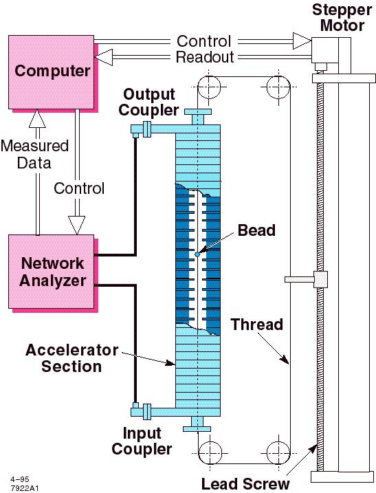
44 Tuning and Structure Characterization

 Electrical field amplitudes along the structure.")

45 Example of Phases and Amplitudes along the Axis of a 77-Cell TW Accelerator Typical modulation due to uncompleted tuning of output coupler Phases and amplitudes plotted in a complex plane (5π/6 mode structure, 2x150º=300º per cell for reflection) Electrical field amplitudes along the structure. There are small amplitude and phase modulation due to slightly imperfections of the couplers, which almost no impact to the power efficiency and beam acceleration.

 = 2 S")

46 Reflection and Transmission f Wiggles due to the beating of reflections from slightly mismatched input/output couplers. f 1 2 T f Transmitted power (left to the load) = 2 S 21 2 S 12 Reflected S 11 from input coupler as a function of frequencies. Transmission S 12 from input port to output port as a function of frequencies.

47 Vacuum Baking of Two Structures 650 C 10 days

48 Alignment Measurement Using CMM Machine
49 4. Fabrication Technology and Locations
50 Fabrication Locations 1. National Laboratories for the X-Band Structures: SLAC KEK LLNL 2. Private Vendors for the X-Band Structures: US Robertson Precision, Inc. (California) LeVezzi Precision, Inc. (Illinois) Japan IHI Morikawa co. Europe VDL Enabling Technologies Group (Netherland)
51 Manufacturability Case of Small Amount Production (less than few hundreds) Case of Mass Production (10k for future X-Band compact FEL or even 1.8 millions precisely machined parts for Linear Collider, which was studied extensively in late 1990s) Design of Manufacturability (DFM) Studies with Huge Cost Reduction
Fabrication Techniques for the X-band Accelerator Structures. Juwen Wang WORKSHOP ON X-BAND RF TECHNOLOGY FOR FELs March 5, 2010
 Fabrication Techniques for the X-band Accelerator Structures Juwen Wang WORKSHOP ON X-BAND RF TECHNOLOGY FOR FELs March 5, 2010 Outline 1. Introduction Brief history Achievements 2. Basics of X-Band Accelerator
High Gradient Studies at the NLC Test Accelerator (NLCTA)
") Chris Adolphsen High Gradient Studies at the NLC Test Accelerator (NLCTA) NLCTA Linac RF Unit (One of Two) Contributors C. Adolphsen, G. Bowden, D. Burke, J. Cornuelle, S. Dobert, V. Dolgashev, J. Frisch,
Chris Adolphsen High Gradient Studies at the NLC Test Accelerator (NLCTA) NLCTA Linac RF Unit (One of Two) Contributors C. Adolphsen, G. Bowden, D. Burke, J. Cornuelle, S. Dobert, V. Dolgashev, J. Frisch,
International Technology Recommendation Panel. X-Band Linear Collider Path to the Future. RF System Overview. Chris Adolphsen
 International Technology Recommendation Panel X-Band Linear Collider Path to the Future RF System Overview Chris Adolphsen Stanford Linear Accelerator Center April 26-27, 2004 Delivering the Beam Energy
HIGH-GRADIENT TESTING OF SINGLE-CELL TEST CAVITIES AT KEK / NEXTEF
 Presented at the 13th Annual Meeting of Particle Accelerator Society of Japan, Aug. 2016 (Paper ID: MOP015) 1 HIGH-GRADIENT TESTING OF SINGLE-CELL TEST CAVITIES AT KEK / NEXTEF Tetsuo Abe, Yoshio Arakida,
PROGRESS OF X-BAND ACCELERATING STRUCTURES
 PROGRESS OF X-BAND ACCELERATING STRUCTURES T. Higo #, KEK, Tsukuba, Ibaraki 305-0801, Japan Abstract In the present paper, we try to review the progress on high gradient X-band accelerator structures for
Attosecond Diagnostics of Muti GeV Electron Beams Using W Band Deflectors
 Attosecond Diagnostics of Muti GeV Electron Beams Using W Band Deflectors V.A. Dolgashev, P. Emma, M. Dal Forno, A. Novokhatski, S. Weathersby SLAC National Accelerator Laboratory FEIS 2: Femtosecond Electron
Christopher Nantista ISG8 SLAC June 25, 2002
 Christopher Nantista ISG8 SLAC June 25, 2002 TM 01 Mode Launcher Development Developed for upcoming traveling-wave single- structure tests as part of R&D to solve rf breakdown problem. Launchers to be
X-Band Linear Collider Report*
 SLAC DOE Program Review X-Band Linear Collider Path to the Future X-Band Linear Collider Report* D. L. Burke NLC Program Director * Abstracted from recent presentations to the International Technical Recommendation
BASIC STUDY ON HIGH-GRADIENT ACCELERATING STRUCTURES AT KEK / NEXTEF
 BASIC STUDY ON HIGH-GRADIENT ACCELERATING STRUCTURES AT KEK / NEXTEF Tetsuo Abe, Yoshio Arakida, Toshiyasu Higo, Shuji Matsumoto, Toshikazu Takatomi, KEK, Tsukuba, Ibaraki 305-0801, Japan Abstract So far,
RF Design of Normal Conducting Deflecting Cavity
 RF Design of Normal Conducting Deflecting Cavity Valery Dolgashev (SLAC), Geoff Waldschmidt, Ali Nassiri (Argonne National Laboratory, Advanced Photon Source) 48th ICFA Advanced Beam Dynamics Workshop
Cavity BPMs for the NLC
 SLAC-PUB-9211 May 2002 Cavity BPMs for the NLC Ronald Johnson, Zenghai Li, Takashi Naito, Jeffrey Rifkin, Stephen Smith, and Vernon Smith Stanford Linear Accelerator Center, 2575 Sand Hill Road, Menlo
Design and RF Measurements of an X-band Accelerating Structure for the Sparc Project
 Design and RF Measurements of an X-band Accelerating Structure for the Sparc Project INFN-LNF ; UNIVERSITY OF ROME LA SAPIENZA ; INFN - MI Presented by BRUNO SPATARO Erice, Sicily, October 9-14; 2005 SALAF
Progress in High Gradient Accelerator Research at MIT
 Progress in High Gradient Accelerator Research at MIT Presented by Richard Temkin MIT Physics and Plasma Science and Fusion Center May 23, 2007 MIT Accelerator Research Collaborators MIT Plasma Science
Cavity BPM With Dipole-Mode Selective Coupler
 Cavity BPM With Dipole-Mode Selective Coupler Zenghai Li Advanced Computations Department Stanford Linear Accelerator Center Presented at PAC23 Portland, Oregon. May 12-16, 23 Work supported by the U.S.
CERN EUROPEAN ORGANIZATION FOR NUCLEAR RESEARCH INVESTIGATION OF A RIDGE-LOADED WAVEGUIDE STRUCTURE FOR CLIC X-BAND CRAB CAVITY
 CERN EUROPEAN ORGANIZATION FOR NUCLEAR RESEARCH CLIC Note 1003 INVESTIGATION OF A RIDGE-LOADED WAVEGUIDE STRUCTURE FOR CLIC X-BAND CRAB CAVITY V.F. Khan, R. Calaga and A. Grudiev CERN, Geneva, Switzerland.
High-field test at KEK
 High-field test at KEK CLIC Workshop Oct. 16-18, CERN T. Higo, KEK Contributors Accelerator S. Fukuda S. Matsumoto M. Akemoto M. Yoshida K. Yokoyama N. Kudoh T. Higo Total FTE = 4~5 KEK MEC staff K. Ueno
Stanford Linear Accelerator Center, Stanford University, Stanford, CA Abstract
 SLAC-PUB-7488 May 1997 RF Systems for the NLCTA* J. W. Wang, C. Adolphsen, R. Atkinson, W. Baumgartner,J. Eichner, R.W. F & &, $ L F 3 S. M. Hanna, S.G.Holmes, R. F. Koontz, T.L. Lavine, R.J. Loewen, R.
NanoBPM tests in the ATF extraction line
 NLC - The Next Linear Collider Project NanoBPM tests in the ATF extraction line Calibrate movers (tilters) and BPM s Understand and test dynamic range and resolution June 2003 Marc Ross What are the uses
Performance Measurements of SLAC's X-band. High-Power Pulse Compression System (SLED-II)
") SLAC PUB 95-6775 June 995 Performance Measurements of SLAC's X-band High-Power Pulse Compression System (SLED-II) Sami G. Tantawi, Arnold E. Vlieks, and Rod J. Loewen Stanford Linear Accelerator Center
SLAC PUB 95-6775 June 995 Performance Measurements of SLAC's X-band High-Power Pulse Compression System (SLED-II) Sami G. Tantawi, Arnold E. Vlieks, and Rod J. Loewen Stanford Linear Accelerator Center
Room Temperature High Repetition Rate RF Structures for Light Sources
 Room Temperature High Repetition Rate RF Structures for Light Sources Sami G. Tantawi SLAC Claudio Pellegrini, R. Ruth, J. Wang. V. Dolgashev, C. Bane, Zhirong Huang, Jeff Neilson, Z. Li Outline Motivation
Precision RF Beam Position Monitors for Measuring Beam Position and Tilt Progress Report
 Precision RF Beam Position Monitors for Measuring Beam Position and Tilt Progress Report UC Berkeley Senior Personnel Yury G. Kolomensky Collaborating Institutions Stanford Linear Accelerator Center: Marc
Resonant Excitation of High Order Modes in the 3.9 GHz Cavity of LCLS-II Linac
 Resonant Excitation of High Order Modes in the 3.9 GHz Cavity of LCLS-II Linac LCLS-II TN-16-05 9/12/2016 A. Lunin, T. Khabiboulline, N. Solyak, A. Sukhanov, V. Yakovlev April 10, 2017 LCLSII-TN-16-06
FAST RF KICKER DESIGN
 FAST RF KICKER DESIGN David Alesini LNF-INFN, Frascati, Rome, Italy ICFA Mini-Workshop on Deflecting/Crabbing Cavity Applications in Accelerators, Shanghai, April 23-25, 2008 FAST STRIPLINE INJECTION KICKERS
Development of the X-band structure at Fermilab
 Development of the X-band structure at Fermilab Outline: N. Solyak Infrastructure and History Production & FY04 schedule Calculations RF QC Girder studies (Slides from MAC, AAC and meeting presentations.
Normal-conducting high-gradient rf systems
 Normal-conducting high-gradient rf systems Introduction Motivation for high gradient Order of 100 GeV/km Operational and state-of-the-art SwissFEL C-band linac: Just under 30 MV/m CLIC prototypes: Over
Christopher Nantista ISG-X SLAC June 17, 2003
 Christopher Nantista ISG-X SLAC June 17, 2003 8-Pack Phase II NLC/JGLC R2 requirement: a linac subunit test rf power distribution dual-moded SLED-II eight 60cm structures Goals: Transport several hundred
The Next Linear Collider Test Accelerator s RF Pulse Compression and Transmission Systems
 SLAC-PUB-7247 February 1999 The Next Linear Collider Test Accelerator s RF Pulse Compression and Transmission Systems S. G. Tantawi et al. Presented at the 5th European Particle Accelerator Conference
Multimoded RF Systems for Future Linear Colliders. Sami G. Tantawi
 Multimoded RF Systems for Future Linear Colliders Sami G. Tantawi Acknowledgment This work is a result of a continuous effort by many researches and engineers over many years. In particular, The efforts
NLC - The Next Linear Collider Project. NLC Update. CLIC Group. CERN September D. L. Burke SLAC
 NLC Update CLIC Group September 2003 SLAC Configuration Electron Injector 560 m ~10 m 170 m Pre-Linac 6 GeV (S) Compressor 136 MeV (L) 2 GeV (S) ~100 m 0.6 GeV (X) ~20 m Compressor Damping Ring e (UHF)
The TESLA Linear Collider. Winfried Decking (DESY) for the TESLA Collaboration
 for the TESLA Collaboration") The TESLA Linear Collider Winfried Decking (DESY) for the TESLA Collaboration Outline Project Overview Highlights 2000/2001 Publication of the TDR Cavity R&D TTF Operation A0 and PITZ TESLA Beam Dynamics
The TESLA Linear Collider Winfried Decking (DESY) for the TESLA Collaboration Outline Project Overview Highlights 2000/2001 Publication of the TDR Cavity R&D TTF Operation A0 and PITZ TESLA Beam Dynamics
Physics Requirements Document Document Title: SCRF 1.3 GHz Cryomodule Document Number: LCLSII-4.1-PR-0146-R0 Page 1 of 7
 Document Number: LCLSII-4.1-PR-0146-R0 Page 1 of 7 Document Approval: Originator: Tor Raubenheimer, Physics Support Lead Date Approved Approver: Marc Ross, Cryogenic System Manager Approver: Jose Chan,
Maurizio Vretenar Linac4 Project Leader EuCARD-2 Coordinator
 Maurizio Vretenar Linac4 Project Leader EuCARD-2 Coordinator Every accelerator needs a linac as injector to pass the region where the velocity of the particles increases with energy. At high energies (relativity)
Detection of Beam Induced Dipole-Mode Signals in the SLC S-Band Structures* Abstract
 -. SLAC-PUB-79 June 1997 Detection of Beam nduced Dipole-Mode Signals in the SLC S-Band Structures* M. Seidel, C. Adolphsen, R. Assmann, D.H. Whittum Stanford Linear Accelerator Center, Stanford University,
Status of Warm-Cold Linear Collider Competition
 Status of Warm-Cold Linear Collider Competition Nick Walker (DESY) SRF 2003 Travemünde 12.09.2003 What s in Store? Pedestrians Guide to e + e - linear colliders The Findings of the 2 nd International Linear
Demonstration of exponential growth and saturation at VUV wavelengths at the TESLA Test Facility Free-Electron Laser. P. Castro for the TTF-FEL team
 Demonstration of exponential growth and saturation at VUV wavelengths at the TESLA Test Facility Free-Electron Laser P. Castro for the TTF-FEL team 100 nm 1 Å FEL radiation TESLA Test Facility at DESY
CLIC Compact Linear Collider
 f1 CLIC Compact LInear Collider Frank Zimmermann for the CLIC Study Team many CLIC contributors! special thanks to Hans Braun, Jean-Pierre Delahaye, & Frank Tecker! Frank Zimmermann UPHUK3 2007, Bodrumr,
Using Higher Order Modes in the Superconducting TESLA Cavities for Diagnostics at DESY
 Using Higher Order Modes in the Superconducting TESLA Cavities for Diagnostics at FLASH @ DESY N. Baboi, DESY, Hamburg for the HOM team : S. Molloy 1, N. Baboi 2, N. Eddy 3, J. Frisch 1, L. Hendrickson
Electromagnetic characterization of materials for the CLIC Damping Rings and high frequency issues
 Electromagnetic characterization of materials for the CLIC Damping Rings and high frequency issues Eirini Koukovini-Platia CERN, EPFL Acknowlegdements G. De Michele, C. Zannini, G. Rumolo (CERN) 1 Outline
Accelerator Structure Breakdown Analysis Using Acoustic Sensors
 Accelerator Structure Breakdown Analysis Using Acoustic Sensors NLC Collaboration Meeting November 2002 Janice Nelson Contributors, M. Ross, T. Smith, F. Le Pimpec, D. McCormick, K. Jobe, J. Frisch, F.
THE ORION PHOTOINJECTOR: STATUS and RESULTS
 THE ORION PHOTOINJECTOR: STATUS and RESULTS Dennis T. Palmer SLAC / ARDB ICFA Sardinia 4 July 2002 1. Introduction 2. Beam Dynamics Simulations 3. Photoinjector 1. RF Gun 2. Solenoidal Magnet 3. Diagnostics
SIMULATIONS OF TRANSVERSE HIGHER ORDER DEFLECTING MODES IN THE MAIN LINACS OF ILC
 SIMULATIONS OF TRANSVERSE HIGHER ORDER DEFLECTING MODES IN THE MAIN LINACS OF ILC C.J. Glasman, R.M. Jones, I. Shinton, G. Burt, The University of Manchester, Manchester M13 9PL, UK Cockcroft Institute
REVIEW OF HIGH POWER CW COUPLERS FOR SC CAVITIES. S. Belomestnykh
 REVIEW OF HIGH POWER CW COUPLERS FOR SC CAVITIES S. Belomestnykh HPC workshop JLAB, 30 October 2002 Introduction Many aspects of the high-power coupler design, fabrication, preparation, conditioning, integration
Crab Cavity Systems for Future Colliders. Silvia Verdú-Andrés, Ilan Ben-Zvi, Qiong Wu (Brookhaven National Lab), Rama Calaga (CERN)
, Rama Calaga (CERN)") International Particle Accelerator Conference Copenhagen (Denmark) 14-19 May, 2017 Crab Cavity Systems for Future Colliders Silvia Verdú-Andrés, Ilan Ben-Zvi, Qiong Wu (Brookhaven National Lab), Rama Calaga
International Particle Accelerator Conference Copenhagen (Denmark) 14-19 May, 2017 Crab Cavity Systems for Future Colliders Silvia Verdú-Andrés, Ilan Ben-Zvi, Qiong Wu (Brookhaven National Lab), Rama Calaga
HIGH POWER INPUT COUPLERS FOR THE STF BASELINE CAVITY SYSTEM AT KEK
 HIGH POWER INPUT COUPLERS FOR THE STF BASELINE CAVITY SYSTEM AT KEK E. Kako #, H. Hayano, S. Noguchi, T. Shishido, K. Watanabe and Y. Yamamoto KEK, Tsukuba, Ibaraki, 305-0801, Japan Abstract An input coupler,
Third Harmonic Superconducting passive cavities in ELETTRA and SLS
 RF superconductivity application to synchrotron radiation light sources Third Harmonic Superconducting passive cavities in ELETTRA and SLS 2 cryomodules (one per machine) with 2 Nb/Cu cavities at 1.5 GHz
CLIC Power Extraction and Transfer Structure. (2004)
") CLIC Power Extraction and Transfer Structure. (24) CLIC linac subunit layout: CLIC accelerating Structure (HDS) Main beam 3 GHz, 2 MW per structure Drive beam (64 A) CLIC Power Extraction and Transfer
CLIC Power Extraction and Transfer Structure. (24) CLIC linac subunit layout: CLIC accelerating Structure (HDS) Main beam 3 GHz, 2 MW per structure Drive beam (64 A) CLIC Power Extraction and Transfer
Normal-Conducting Photoinjector for High Power CW FEL
 LA-UR-04-5617,-5808 www.arxiv.org: physics/0404109 Normal-Conducting Photoinjector for High Power CW FEL Sergey Kurennoy, LANL, Los Alamos, NM, USA An RF photoinjector capable of producing high continuous
DQW HOM Coupler for LHC
 DQW HOM Coupler for LHC J. A. Mitchell 1, 2 1 Engineering Department Lancaster University 2 BE-RF-BR Section CERN 03/07/2017 J. A. Mitchell (PhD Student) HL LHC UK Jul 17 03/07/2017 1 / 27 Outline 1 LHC
... George Gollin. University of Illinois at Urbana-Champaign and Fermi National Accelerator Laboratory
 George Gollin, Damping ring kicker, December 15, 2004 1 I hysics Fourier Series ulse Compression Damping Ring Kicker: a rogress Report George Gollin University of at Urbana-Champaign and Fermi National
FAST KICKERS LNF-INFN
 ILC Damping Rings R&D Workshop - ILCDR06 September 26-28, 2006 at Cornell University FAST KICKERS R&D @ LNF-INFN Fabio Marcellini for the LNF fast kickers study group* * D. Alesini, F. Marcellini P. Raimondi,
HIGHER ORDER MODES FOR BEAM DIAGNOSTICS IN THIRD HARMONIC 3.9 GHZ ACCELERATING MODULES *
 HIGHER ORDER MODES FOR BEAM DIAGNOSTICS IN THIRD HARMONIC 3.9 GHZ ACCELERATING MODULES * N. Baboi #, N. Eddy, T. Flisgen, H.-W. Glock, R. M. Jones, I. R. R. Shinton, and P. Zhang # # Deutsches Elektronen-Synchrotron
CEBAF waveguide absorbers. R. Rimmer for JLab SRF Institute
 CEBAF waveguide absorbers R. Rimmer for JLab SRF Institute Outline Original CEBAF HOM absorbers Modified CEBAF loads for FEL New materials for replacement loads High power loads for next generation FELs
Superstructures; First Cold Test and Future Applications
 Superstructures; First Cold Test and Future Applications DESY: C. Albrecht, V. Ayvazyan, R. Bandelmann, T. Büttner, P. Castro, S. Choroba, J. Eschke, B. Faatz, A. Gössel, K. Honkavaara, B. Horst, J. Iversen,
Proposal of test setup
 Proposal of test setup Status of the study The Compact Linear collider (CLIC) study is a site independent feasibility study aiming at the development of a realistic technology at an affordable cost for
Use of Acoustic Emission to Diagnose Breakdown in Accelerator RF Structures * Abstract
 SLAC PUB 9808 May 2003 Use of Acoustic Emission to Diagnose Breakdown in Accelerator RF Structures * J. Nelson, M. Ross, J. Frisch, F. Le Pimpec, K. Jobe, D. McCormick, T. Smith Stanford Linear Accelerator
The transition for the Elettra Input Power Coupler to the standard WR1800
 The transition for the Elettra Input Power Coupler to the standard WR1800 Cristina Pasotti, Mauro Bocciai, Luca Bortolossi, Alessandro Fabris, Marco Ottobretti, Mauro Rinaldi Alessio Turchet Sincrotrone
LC Technology Hans Weise / DESY
 LC Technology Hans Weise / DESY All you need is... Luminosity! L σ 2 N e x σ y σ y σ x L n b f rep Re-writing reflects the LC choices... L P E b c. m. N e σ σ x y... beam power... bunch population... Ac-to-beam
High acceleration gradient. Critical applications: Linear colliders e.g. ILC X-ray FELs e.g. DESY XFEL
 High acceleration gradient Critical applications: Linear colliders e.g. ILC X-ray FELs e.g. DESY XFEL Critical points The physical limitation of a SC resonator is given by the requirement that the RF magnetic
Beam BreakUp at Daresbury. Emma Wooldridge ASTeC
 Beam BreakUp at Daresbury Emma Wooldridge ASTeC Outline The causes of Beam Breakup (BBU) Types of BBU Why investigate BBU? Possible solutions Causes of BBU There are four main causes. Interaction with
MULTIPACTING IN THE CRAB CAVITY
 MULTIPACTING IN TH CRAB CAVITY Y. Morita, K. Hara, K. Hosoyama, A. Kabe, Y. Kojima, H. Nakai, KK, 1-1, Oho, Tsukuba, Ibaraki 3-81, JAPAN Md. M. Rahman, K. Nakanishi, Graduate University for Advanced Studies,
Review of New Shapes for Higher Gradients
 Review of New Shapes for Higher Gradients Rong-Li Geng LEPP, Cornell University Rong-Li Geng SRF2005, July 10-15, 2005 1 1 TeV 800GeV 500GeV ILC(TESLA type) energy reach Rapid advances in single-cell cavities
Experience with 3.9 GHz cavity HOM couplers
 Cornell University, October 11-13, 2010 Experience with 3.9 GHz cavity HOM couplers T. Khabiboulline, N. Solyak, FNAL. 3.9 GHz cavity general parameters Third harmonic cavity (3.9GHz) was proposed to compensate
High Power Couplers for TTF - FEL
 High Power Couplers for TTF - FEL 1. Requirements for High Power Couplers on superconducting Cavities 2. Characteristics of pulsed couplers 3. Standing wave pattern in the coaxial coupler line 4. Advantages
Project X Cavity RF and mechanical design. T. Khabiboulline, FNAL/TD/SRF
 Project X Cavity RF and mechanical design T. Khabiboulline, FNAL/TD/SRF TTC meeting on CW-SRF, 2013 Project X Cavity RF and mechanical design T 1 High ß Low ß 0.5 HWR SSR1 SSR2 0 1 10 100 1 10 3 1 10 4
A Design of a 3rd Harmonic Cavity for the TTF 2 Photoinjector
 TESLA-FEL 2002-05 A Design of a 3rd Harmonic Cavity for the TTF 2 Photoinjector J. Sekutowicz, R. Wanzenberg DESY, Notkestr. 85, 22603 Hamburg, Germany W.F.O. Müller, T. Weiland TEMF, TU Darmstadt, Schloßgartenstr.
RF Cavity Design. Erk Jensen CERN BE/RF. CERN Accelerator School Accelerator Physics (Intermediate level) Darmstadt 2009
 Darmstadt 2009") RF Cavity Design Erk Jensen CERN BE/RF CERN Accelerator School Accelerator Physics (Intermediate level) Darmstadt 009 CAS Darmstadt '09 RF Cavity Design 1 Overview DC versus RF Basic equations: Lorentz
RF Cavity Design Erk Jensen CERN BE/RF CERN Accelerator School Accelerator Physics (Intermediate level) Darmstadt 009 CAS Darmstadt '09 RF Cavity Design 1 Overview DC versus RF Basic equations: Lorentz
COMPARISON OF BUFFERED CHEMICAL POLISHED AND ELECTROPOLISHED 3.9 GHz CAVITIES*
 COMPARISON OF BUFFERED CHEMICAL POLISHED AND ELECTROPOLISHED 3.9 GHz CAVITIES* H. Edwards #, C.A. Cooper, M. Ge, I.V. Gonin, E.R. Harms, T. N. Khabiboulline, N. Solyak Fermilab, Batavia IL, USA Abstract
Cavity development for TESLA
 Cavity development for TESLA Lutz.Lilje@desy.de DESY -FDET- Cavity basics History: Limitations and solutions»material inclusions»weld defects»field emission»increased surface resistance at high field Performance
Report of working group 5
 Report of working group 5 Materials Cavity design Cavity Fabrication Preparatioin & Testing Power coupler HOM coupler Beam line absorber Tuner Fundamental R&D items Most important R&D items 500 GeV parameters
The impedance budget of the CERN Proton Synchrotron (PS)
") The impedance budget of the CERN Proton Synchrotron (PS) Serena Persichelli CERN Hadron Synchrotron Collective effects University of Rome La Sapienza serena.persichelli@cern.ch Why do we study the beam
The impedance budget of the CERN Proton Synchrotron (PS) Serena Persichelli CERN Hadron Synchrotron Collective effects University of Rome La Sapienza serena.persichelli@cern.ch Why do we study the beam
HOM/LOM Coupler Study for the ILC Crab Cavity*
 SLAC-PUB-1249 April 27 HOM/LOM Coupler Study for the ILC Crab Cavity* L. Xiao, Z. Li, K. Ko, SLAC, Menlo Park, CA9425, U.S.A Abstract The FNAL 9-cell 3.9GHz deflecting mode cavity designed for the CKM
Tuning systems for superconducting cavities at Saclay
 Tuning systems for superconducting cavities at Saclay 1 MACSE: 1990: tuner in LHe bath at 1.8K TTF: 1995 tuner at 1.8K in the insulating vacuum SOLEIL: 1999 tuner at 4 K in the insulating vacuum Super-3HC:
Third Harmonic Cavity Status
 Third Harmonic Cavity Status General parameters Cavity design Main coupler calculation HOM analysis and HOM coupler design Lorentz Forces and Stress analysis Summary General parameters Third harmonic cavity
Cornell ERL s Main Linac Cavities
 Cornell ERL s Main Linac Cavities N. Valles for Cornell ERL Team 1 Overview RF Design Work Cavity Design Considerations Optimization Methods Results Other Design Considerations Coupler Kicks Stiffening
SwissFEL Design and Status
 SwissFEL Design and Status Hans H. Braun Mini Workshop on Compact X ray Free electron Lasers Eastern Forum of Science and Technology Shanghai July 19, 2010 SwissFEL, the next large facility at PSI SwissFEL
COUPLER DESIGN CONSIDERATIONS FOR THE ILC CRAB CAVITY
 COUPLER DESIGN CONSIDERATIONS FOR THE ILC CRAB CAVITY C. Beard 1), G. Burt 2), A. C. Dexter 2), P. Goudket 1), P. A. McIntosh 1), E. Wooldridge 1) 1) ASTeC, Daresbury laboratory, Warrington, Cheshire,
On the RF system of the ILC
 On the RF system of the ILC Sami G. Tantawi Chris Nantista Valery Dolgashev Jiquan Guo SLAC Outline This talk is a collection of thoughts about the rf system based on our experience with X-band system!
Main Injector Cavity Simulation and Optimization for Project X
 Main Injector Cavity Simulation and Optimization for Project X Liling Xiao Advanced Computations Group Beam Physics Department Accelerator Research Division Status Meeting, April 7, 2011 Outline Background
Breakdown in Waveguides and Components
 Breakdown in Waveguides and Components Alfred Moretti Fermilab ILC Snowmass Workshop August 16, 2005 08/16/2005 Alfred Moretti 1 Outline of Talk 1) Description of the RF high Power System 2) Breakdown
2 Theory of electromagnetic waves in waveguides and of waveguide components
 RF transport Stefan Choroba DESY, Hamburg, Germany Abstract This paper deals with the techniques of transport of high-power radiofrequency (RF) power from a RF power source to the cavities of an accelerator.
Snowmass WG5: Superconducting Cavities and Couplers (Draft August 12, 2005 Rong-Li Geng) Topic 1: Cavity Shape
 Topic 1: Cavity Shape") Snowmass WG5: Superconducting Cavities and Couplers (Draft August 12, 2005 Rong-Li Geng) Topic 1: Cavity Shape Overview The cavity shape determines the fundamental mode as well as the higher order modes
Snowmass WG5: Superconducting Cavities and Couplers (Draft August 12, 2005 Rong-Li Geng) Topic 1: Cavity Shape Overview The cavity shape determines the fundamental mode as well as the higher order modes
HOM Based Diagnostics at the TTF
 HOM Based Diagnostics at the TTF Nov 14, 2005 Josef Frisch, Nicoleta Baboi, Linda Hendrickson, Olaf Hensler, Douglas McCormick, Justin May, Olivier Napoly, Rita Paparella, Marc Ross, Claire Simon, Tonee
O. Napoly LC02, SLAC, Feb. 5, Higher Order Modes Measurements
 O. Napoly LC02, SLAC, Feb. 5, 2002 Higher Order Modes Measurements with Beam at the TTF Linac TTF Measurements A collective effort including most of Saclay, Orsay and DESY TTF physicists : S. Fartoukh,
Advance on High Power Couplers for SC Accelerators
 Advance on High Power Couplers for SC Accelerators Eiji Kako (KEK, Japan) IAS conference at Hong Kong for High Energy Physics, 2017, January 23th Eiji KAKO (KEK, Japan) IAS at Hong Kong, 2017 Jan. 23 1
Next Linear Collider Beam Position Monitors
 NLC - The Project Beam Position Monitors Steve Smith SLAC October 23, 2002 What s novel, extreme, or challenging? Push resolution frontier Novel cavity BPM design for high resolution, stability Push well
Development of a 20-MeV Dielectric-Loaded Accelerator Test Facility
 SLAC-PUB-11299 Development of a 20-MeV Dielectric-Loaded Accelerator Test Facility S.H. Gold, et al. Contributed to 11th Advanced Accelerator Concepts Workshop (AAC 2004), 06/21/2004--6/26/2004, Stony
Status and Plans for the 805 MHz Box Cavity MuCool RF Workshop III 07/07/09 Al Moretti
 Status and Plans for the 805 MHz Box Cavity MuCool RF Workshop III 07/07/09 Al Moretti 7/6/2009 1 Outline : Description of the Box cavity Concept. Box Cavity Summary Plans. HFSS Models of orthogonal and
STATUS OF THE ILC CRAB CAVITY DEVELOPMENT
 STATUS OF THE ILC CRAB CAVITY DEVELOPMENT SLAC-PUB-4645 G. Burt, A. Dexter, Cockcroft Institute, Lancaster University, LA 4YR, UK C. Beard, P. Goudket, P. McIntosh, ASTeC, STFC, Daresbury laboratories,
W-band vector network analyzer based on an audio lock-in amplifier * Abstract
 SLAC PUB 7884 July 1998 W-band vector network analyzer based on an audio lock-in amplifier * R. H. Siemann Stanford Linear Accelerator Center, Stanford University, Stanford CA 94309 Abstract The design
STATE OF THE ART IN EM FIELD COMPUTATION*
 SLAC-PUB-12020 August 2006 STATE OF THE ART IN EM FIELD COMPUTATION* C. Ng, V. Akcelik, A. Candel, S. Chen, N. Folwell, L. Ge, A. Guetz, H. Jiang, A. Kabel, L.-Q. Lee, Z. Li, E. Prudencio, G. Schussman,
3.9 GHz Deflecting Mode Cavity
 3.9 GHz Deflecting Mode Cavity Timothy W. Koeth July 12, 2005 History of 3.9 GHz DMC Cavity Simulations The Other Modes concern and modeling R/Q Wake Field Simulations Design: OM couplers Testing: Vertical
Design of ESS-Bilbao RFQ Linear Accelerator
 Design of ESS-Bilbao RFQ Linear Accelerator J.L. Muñoz 1*, D. de Cos 1, I. Madariaga 1 and I. Bustinduy 1 1 ESS-Bilbao *Corresponding author: Ugaldeguren III, Polígono A - 7 B, 48170 Zamudio SPAIN, jlmunoz@essbilbao.org
3.9 GHz work at Fermilab
 3.9 GHz work at Fermilab + CKM 13-cell cavity Engineering and designing W.-D. Moeller Desy, MHF-sl Protocol of the meeting about 3 rd harmonic cavities during the TESLA collaboration meeting at DESY on
NEW OPPORTUNITIES IN VACUUM ELECTRONICS USING PHOTONIC BAND GAP STRUCTURES
 NEW OPPORTUNITIES IN VACUUM ELECTRONICS USING PHOTONIC BAND GAP STRUCTURES J. R. Sirigiri, C. Chen, M. A. Shapiro, E. I. Smirnova, and R. J. Temkin Plasma Science and Fusion Center Massachusetts Institute
Status of the HOM Damped Cavity Project
 Status of the HOM Damped Cavity Project E. Weihreter / BESSY for the HOM Damped Cavity Collaboration BESSY, Daresbury Lab, DELTA, MaxLab, NTHU Project funded by the EC under contract HPRI-CT-1999-50011
Design of S-band re-entrant cavity BPM
 Nuclear Science and Techniques 20 (2009) 133 139 Design of S-band re-entrant cavity BPM LUO Qing SUN Baogen * HE Duohui National Synchrotron Radiation Laboratory, School of Nuclear Science and Technology,
Accelerating Cavities
 Accelerating Cavities for the Damping Ring (DR) Tetsuo ABE For KEKB RF/ARES Cavity Group (T. Abe, T. Kageyama, H. Sakai, Y. Takeuchi, and K. Yoshino) The 16 th KEKB Accelerator Review Meeting February
Accelerator Technology and High Gradient Collaboration
 Accelerator Technology and High Gradient Collaboration Sami Tantawi (Accelerator Technology Research Department) Gordon Bowden, Valery Dolgashev, Hattie Dong, David Farkas, John Fox, Jiquan Guo, Jim Lewandowski,
Invited talk presented at The Computational Accelerator Conference (CAP 93) Pleasanton, CA February 22-26, 2993
 Pleasanton, CA February 22-26, 2993") MODELING ACCELERATOR STRUCTURES AND RF COMPONENTS* K. Ko, C.-K. Ng and W. B. Herrmannsfeldt Stanford Linear Accelerator Center Stanford University, Stanford, CA 94309 SLAC-PUB-6084 March 1993 (A) I ABSTRACT
MODELING ACCELERATOR STRUCTURES AND RF COMPONENTS* K. Ko, C.-K. Ng and W. B. Herrmannsfeldt Stanford Linear Accelerator Center Stanford University, Stanford, CA 94309 SLAC-PUB-6084 March 1993 (A) I ABSTRACT
200 MHz 350 MHz 750 MHz Linac2 RFQ2 202 MHz 0.5 MeV /m Weight : 1000 kg/m Ext. diameter : 45 cm
 M. Vretenar, CERN for the HF-RFQ Working Group (V.A. Dimov, M. Garlasché, A. Grudiev, B. Koubek, A.M. Lombardi, S. Mathot, D. Mazur, E. Montesinos, M. Timmins, M. Vretenar) 1 1988-92 Linac2 RFQ2 202 MHz