BASIC STUDY ON HIGH-GRADIENT ACCELERATING STRUCTURES AT KEK / NEXTEF
|
|
|
- Dominick Perkins
- 5 years ago
- Views:
Transcription
1 BASIC STUDY ON HIGH-GRADIENT ACCELERATING STRUCTURES AT KEK / NEXTEF Tetsuo Abe, Yoshio Arakida, Toshiyasu Higo, Shuji Matsumoto, Toshikazu Takatomi, KEK, Tsukuba, Ibaraki , Japan Abstract So far, we have developed X-band high-gradient accelerating structures of prototypes for normal-conducting linear colliers in a comprehensive way, establishing a full production process of fabrication and test. On the other hand, focusing on the fact that we do not know both the highgradient limit of performance and breakdown trigger mechanism on the normal-conducting RF acceleration, we have been preparing a new test stand for a fresh basic study on vacuum breakdown, where we use compact test structures with an RF field concentrated in a single test cell. In this paper, we report the status of the new test stand called Shield-B together with a list of test structures ready for high-gradient test or under fabrication. INTRODUCTION X-band (11.4 GHz) normal-conducting RF acceleration technology can be applied to high-gradient accelerators, such as compact linear colliders and medical linacs. Based on the development results and experiences through the NLC/GLC projects (aiming at an operational gradient of 65 MV/m) [1], high-gradient accelerating structures with higher-order-mode (HOM) damped structure (hereinafter simply referred to as damped structure ) have been developed, aiming at an operational gradient of 100 MV/m [2]. We also have been establishing a full production process of fabrication and test of prototype structures, including 1. Machining of components, such as disks and waveguides, 2. Cleaning and surface process, such as chemical polishing of disks, 3. Diffusion bonding of disks, 4. Assembly, 5. Pretest low-power RF measurement, 6. Vacuum baking, 7. High-gradient test, 8. Posttest low-power RF measurement, and 9. Postmortem by microscopy. One of the recent significant achievements is a highgradient test result of a multi-cell prototype structure for CLIC [3], which meets requirements of CLIC: an accelerating gradient (E acc ) of 100 MV/m, an RF pulse width around 200 ns, a repetition rate of 50 Hz, and a breakdown rate (BDR) lower than /m/pulse although this has no damped structure (undamped structure) [4]. The latest prototype structure for CLIC has a HOM heavily damped structure with waveguides (HOM waveguides), which has about tetsuo.abe@kek.jp two orders of magnitude higher BDR than that of the corresponding undamped one [5]. Although it has been found that such large BDR difference is related to the large surface current around the HOM waveguides [10, 11], we do not yet fully understand the real reason, and in addition, we do not know the real cause of breakdown (breakdown trigger mechanism); these two facts motivate us to perform further basic study on breakdown characteristics of the structures. In parallel with the above-mentioned comprehensive development of multi-cell prototypes, we have been preparing a test stand focused on basic study on vacuum breakdown, in collaboration with the high-gradient accelerating-structure development teams at CERN and SLAC, because such comprehensive development is cost and time consuming. Here, we use compact test cavities with an RF field concentrated in a single test cell coupled with an upstream coupling cell and a downstream end cell. This is a minimum structure keeping a realistic RF field for acceleration in the test cell, and easy to make and test. In this study, we refer to this three-cavity structure as single-cell structure. This type of testing method is originated from [6]. In this paper, we report the status of our new test stand called Shield-B at KEK / Nextef for implementing the above-mentioned agile experimental research, followed by showing accelerating structures to be tested at the test stand in the near future. TEST STAND Figure 1 shows our X-band test facility: Nextef, which consists of two radiation shields of Shield-A and Shield- B. In Shield-A, we perform high-gradient tests of multicell prototypes, while in Shield-B, high-gradient tests for basic study using single-cell structures will be performed. As shown in Fig. 1, the X-band klystron for Shied-B is not located in the same room as Shield-B, so that we have constructed a 30 m-long high-power RF transmission line (power line), as shown with a red dashed line in Fig. 1. The major part of the power line is a low-loss line consisting of a circular waveguide (WC40) for TE 01 mode. The inside of the power line has been evacuated into ultrahigh vacuum. Figure 2 shows the current status of Shield-B, where the power line is terminated by a dummy load. We have been performing RF conditioning of the power line, as shown in Fig. 3, reaching 6.8 MW of input RF power as of July 28, The current target is 10 MW, which corresponds to 100 MW/m at the test cell of a single-cell structure. TEST STRUCTURES All of the test structures shown in this paper:

 dashed line")
.")
![Vacuum Pressure [Pa] X-Band Klystron](/docs-images/92/110507883/images/2-3.jpg "for Shield-B X-Band Klystron for")
![Shield-A Input RF Power [MW] KEK /](/docs-images/92/110507883/images/2-4.jpg "Nextef 6 5 4 3 2 1 0-5 10-6 10 Near the")

![75 100 125 RF-ON Time [hours] Figure 3:](/docs-images/92/110507883/images/2-6.jpg "Status of RF conditioning of the power")


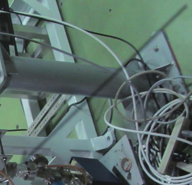


2 Shield-B for Basic Study fo Shield-A for Prototype Development Figure 1: X-band test facility: Nextef. The red (light yellow) dashed line indicates a power line for Shield-B (ShieldA). Vacuum Pressure [Pa] X-Band Klystron for Shield-B X-Band Klystron for Shield-A Input RF Power [MW] KEK / Nextef Near the Klystron Near the Dummy Load WR90 Waveguide from the Klystron RF-ON Time [hours] Figure 3: Status of RF conditioning of the power line until July 28, 2015, where only the data with non-zero input RF power are plotted here. RF power input to the dummy load. Vacuum pressure inside the power line. which will be explained in detail in the following subsections. Undamped Structures Spu!er Ion Pump Dummy Load Figure 2: Photograph of the inside of Shield-B as of July, Consist of three cells of a coupling cell, an end cell, and a test cell in-between, Made of high-purity oxygen-free copper satisfying C10100, where unless otherwise specified, the grain size of the copper material is of the order of 0.1 mm after fabrication, and Are used to excite π-mode like standing wave as an accelerating mode. We have various test structures to be high-gradient tested and compared, as classified and summarized in Tab. 1, Although our ultimate goal is to have an damped structure with a sufficiently-low BDR at Eacc = 100 MV/m or higher, undamped structures are useful to understand basic characteristics of test structures on geometries, materials, machining, cleaning, and other characteristics not related to the damped structure. What is also important is that an undamped structure, made of usual material, machined and fabricated in a usual way for prototype structures can be a reference in BDR measurements. Hereinafter referred to this cavity as standard cavity. Standard cavity Although there are various geometries of undamped single-cell structures tested so far [7], we have chosen a geometry with an iris aperture radius of a = 3.75 mm and iris thickness of t = 2.6 mm as a standard geometry in this study. Figure 4a shows its solid model. This geometry can be machined only by turning with an arithmetical mean roughness (Ra ) of 0.03 to 0.1 µm for the inner surface, where the skin depth of copper is 0.5 µm at 11.4 GHz. Figure 4b and 4c show RF field of the accelerating mode (π-mode like). Frequency of the coupling and end cells are slightly detuned so that the field strength in the test cell is almost double of those in the coupling and end cells as shown in Fig. 5.


 TM01 in WC90 φ12 φ12.")

, we use a reusable mode converter to launch TM01 mode")
![in a circular waveguide (WC90) [8] located close to the test structure. Such mode converter can be used for any other test cavities.](/docs-images/92/110507883/images/3-5.jpg "Figure 6 shows a conceptual diagram including the mode converter. Figure 4: RF simulation for the standard cavity. Solid model (vacuum region).")


3 Table 1: Classification of the materials, methods, and structures to be high-gradient tested at Shield-B. Items described in parentheses indicate future options. Structure Grain size of copper material Undamped Disk-type or 5 to 50 mm (6N) Damped with HOM waveguides Disk-type Quadrant-type Choke-mode damped Disk-type Turning only or Milling only Turning + Milling Milling only Turning only Surface finishing Chemical polishing Chemical polishing None (Advanced polishing) None Bonding method for disks or quadrants Diffusion bonding Diffusion bonding or Brazing EBW (or Brazing) Diffusion bonding Machining method for disks or quadrants TE10 in WR90 φ22.86 (WC90) TM01 in WC90 φ12 φ12.7 RF Figure 6: Standard cavity mounted with the mode converter (TE10 in the rectangular waveguide (WR90) to TM01 in the circular waveguide (WC90)). Solid model of the vacuum region. Snapshot of the electric-field strength shown in log scale. Photograph of a corresponding real setup, including the standard cavity and the mode converter. RF Since RF power is delivered to a test cavity as a TE10 mode in the rectangular waveguide (WR90), we use a reusable mode converter to launch TM01 mode in a circular waveguide (WC90) [8] located close to the test structure. Such mode converter can be used for any other test cavities. Figure 6 shows a conceptual diagram including the mode converter. Figure 4: RF simulation for the standard cavity. Solid model (vacuum region). Electric and magnetic field of the accelerating mode (π-mode like). CPL means coupling. Figure 5: Magnitude of the RF field of the accelerating mode shown as a height of the carpet in linear scale. Input RF wave comes from the right. Electric field strength. Magnetic field strength. Made of large-grain copper Grain boundary is one of the most significant crystal defects. There is speculation that BDR has some correlation with grain boundaries because surface damage by electro-migration [9] is relatively large at grain boundaries. We have been making undamped test cavities with the same geometry as that of the standard cavity with a grain size of 5 to 50 mm from six nines copper. Machined by milling only Damped structures with HOM waveguides cannot be machined without milling. Surface roughness (damage) by milling is large (deep) in case of milling compared with surface by turning, which is guess to have any effect on BDR. We have been making undamped test cavities with the same geometry as that
 surface magnetic field of the the")


![resultant BDR is orders of magnitude higher than that of a corresponding undamped structure, as shown in the recent high-gradient tests [5].](/docs-images/92/110507883/images/4-3.jpg "We study effects of such damped structure with different fabrication methods for comparison, where the coupling and end cells are basically have the same")

 diffusion-bonded We have made disks of the damped test cell, which will be diffusion-bonded with disks of the coupling and")
 brazed By postmortem using microscopy for a CLIC prototype structure after its high-gradient test, microscopic gaps and")
![suspicious objects were found around the diffusion bonded planes [12].](/docs-images/92/110507883/images/4-7.jpg "Brazing of disks might be a good solution, filling those gaps, although the accuracy is supposed to be lower than that by diffusion bonding.")
. End Cell Arbitrary Scale Bead-Pull Measurement 0 20 40 CPL Cell Test Cell φ12.")
![7 ßEnd cell 60 80 100 z [mm] Figure 9: Comparison of the electric-field strength between the bead-pull measurement and simulation. CPL means coupling.](/docs-images/92/110507883/images/4-9.jpg "on TD24R05, as shown in Fig. 8. We have performed lowpower RF measurements, and found no problem with no tuning.")
 Quadranttype structure has a definite advantage that no surface current associated with magnetic field flows across")
![any junction or bonding plane 1 in addition to possible significant cost reduction by the simple machining and assembly [13].](/docs-images/92/110507883/images/4-11.jpg "We once fabricated a quadrant-type prototype structure with 18 cells, and performed a high-gradient test.")
4 (d) RF φ22.86 φ (W (WC90) (d) Figure 7: Test cavity with HOM waveguides. For the solid model shown in, simulation results on the electricfield strength, surface electric field, and (d) surface magnetic field of the the accelerating mode are shown. Also shown in and (d) is curved tetrahedral meshing used in this RF simulation. CPL means coupling. Figure 8: Test cavity with HOM waveguides, where disks were bonded by brazing. Brazing filler metal and grooves. Test brazing of two disks. Checking the brazing performance. (d) Just after the delivery. Simula!on For high-energy applications, damped structures are often required. HOM damping with waveguides is a simple and promising way although surface magnetic field, or surface current, is enhanced around the HOM waveguides, and resultant BDR is orders of magnitude higher than that of a corresponding undamped structure, as shown in the recent high-gradient tests [5]. We study effects of such damped structure with different fabrication methods for comparison, where the coupling and end cells are basically have the same geometry as those of the standard cavity except for the coupling iris. Figure 7a is the solid model, where the design of the test cell is based on the optimized structure for CLIC called TD24R05 [3, 5]. Figure 7b shows magnitude of the electric field, and Fig. 7c (7d) shows the surface electric (magnetic) field strength. Consisting of disks (disk-type) diffusion-bonded We have made disks of the damped test cell, which will be diffusion-bonded with disks of the coupling and end cells in the standard method applied to multi-cell prototype structures. Consisting of disks (disk-type) brazed By postmortem using microscopy for a CLIC prototype structure after its high-gradient test, microscopic gaps and suspicious objects were found around the diffusion bonded planes [12]. Brazing of disks might be a good solution, filling those gaps, although the accuracy is supposed to be lower than that by diffusion bonding. We have made a single-cell damped test cavity by brazing, where the test cell is based End Cell CPL Cell Damped Structures with HOM Waveguides Test Cell of the standard cavity, machined by milling only (without turning). End Cell Arbitrary Scale Bead-Pull Measurement CPL Cell Test Cell φ12.7 ßEnd cell z [mm] Figure 9: Comparison of the electric-field strength between the bead-pull measurement and simulation. CPL means coupling. on TD24R05, as shown in Fig. 8. We have performed lowpower RF measurements, and found no problem with no tuning. Figure 9 shows measured and simulated electricfield strengths along the beam axis, where the measurement is in good agreement with the simulation result. Consisting of quadrants (quadrant-type) Quadranttype structure has a definite advantage that no surface current associated with magnetic field flows across any junction or bonding plane 1 in addition to possible significant cost reduction by the simple machining and assembly [13]. We once fabricated a quadrant-type prototype structure with 18 cells, and performed a high-gradient test. The result was that the accelerating gradient was limited to 60 MV/m or lower, and we observed no conditioning effects [14]. Going back to its basics, we have identified disadvantages of the naive quadrant-type structure, and proposed measures to overcome all of the disadvantages, as shown in Fig. 10. Based on this new design, we have made quadrants of a single-cell structure for high-gradient testing [13]. After the machining of the quadrants by high-precision milling, we performed assembly in a highly-precise way as shown in Fig Typical surface current during X-band high-gradient tests is of the order of 108 A/cm2.


 Figure 11: Precise assembly of the quadrants of the singlecell damped")

 After the last two quadrants aligned.")
 3D drawing of the alignment frame including the quadrants.")


![tolerance for stress originated from the surface current [15].](/docs-images/92/110507883/images/5-10.jpg "Figure 12a is a photograph after the EBW.")


5 The inner surface of this cavity is shaped by high-precision milling, followed by polishing for ultra-smooth surface. 1.5 mm Contact surface End cell elll Test celllll CPL cell elll Thermocouple Large round chamfer Small gap Figure 10: New quadrant-type structure as a single-cell test cavity, which overcomes all of the disadvantages. CPL means coupling. (d) (e) Figure 12: EBW of the quadrants. After the EBW. Welding penetration depth for the EBW conditions described in [13]. A thermocouple is attached. (f) Figure 11: Precise assembly of the quadrants of the singlecell damped structure. One quadrant fixed on an alignment frame. Two quadrants aligned using an alignment block. Replacing the alignment block by two quadrants. (d) After the last two quadrants aligned. (e) During the alignment of the last two quadrants using a CMM. (f) 3D drawing of the alignment frame including the quadrants. After the precise assembly, we have performed electron beam welding (EBW) to bond the four quadrants with EBW conditions described in [13]. Bonding with EBW enables us to make accelerating structures made of hard copper only, leading possibly to lower BDR because of its higher tolerance for stress originated from the surface current [15]. Figure 12a is a photograph after the EBW. Figure 12b shows the welding penetration depth, which is 1.5 mm, and enough from mechanical and vacuum-sealing points of view. During the EBW, we measured temperature of one of the quadrants at a position shown in Fig. 12c, and found that maximum temperature rise measured at the position far from the EBW beads was lower than 10 degc. Finally, we have confirmed no vacuum leak with a background level lower than Pa m3 /s. We have measured the accelerating-mode frequency before and after the EBW by using a pickup antenna, and found that the frequency has become higher by 5.6 MHz. We have also measured transverse lengths by using a CMM before and after the EBW; the length change was 9.7 µm in average around the test cell, which corresponds to 7.2 MHz frequency increase if we assume uniform shrinkage only Figure 13: Photograph of the X-band single-cell test cavity with the choke-mode damped structure in the test cell. CPL means coupling. Courtesy of Tsinghua University. at the contact surface of the adjacent quadrants during the EBW. Therefore, the measured frequency change of 5.6 MHz can be attributed to the transverse uniform shrinkage. It should be emphasized that such frequency change is within the scope of the frequency-tuning mechanism of this test cavity. As for the surface finishing for quadrants, we have been testing an advanced polishing which meets the following requirements [16]: Ultra-smooth surface with Ra < 10 nm, and Applicability to any curved surface. Choke-Mode Damped Structure Choke-mode damped structure [17] is smart in its electrical design with axial symmetry and no enhancement of surface-magnetic field, and is successful at a C-band XFEL facility [18] although such structure is relatively complicated. Our collaborators at Tsinghua University (China) are working to make X-band accelerating structures with such choke-mode damped structure [19]. Figure 13 shows an Xband single-cell test cavity recently made by the team for bonding test and RF measurement. They are fabricating a corresponding test cavity for a high-gradient test to be performed at Shield-B.
6 SCHEDULE The RF conditioning of the power line to Shield-B will be finished this summer. Then, we will replace the dummy load by a test cavity in Shield-B to check and establish the system of the monitoring and data acquisition. We will start the first high-gradient test for the standard cavity this coming autumn, including measurement of a reference BDR, where we will start a gradient range of 80 to 100 MV/m, which corresponds to practical applications. Then, we will step up the gradient, depending on results of the high-gradient test and our scientific interests. After the high-gradient test of the standard cavity, we will select and install a second test cavity from those shown in this paper. SUMMARY Basic study on vacuum breakdown, in the form of single cell, based on the X-band technology developed so far, is beginning at KEK / Nextef / Shield-B, where the klystron is working well, the RF conditioning of the power line is also progressing well, and the first high-gradient test will start this coming autumn. We have many structures to be tested, including undamped and damped structures, structure with large grain, disks machined by turning only and by milling only, chokemode structure, and new quadrants. REFERENCES [1] J. Wang and T. Higo, Accelerator Structure Development for NLC/GLC, ICFA Beam Dynamics Newsletter 32, 27, [2] T. Higo et al., High Gradient Performance of TW Accelerator Structures Targeting 100 MV/m, in Proceedings of the 12th Annual Meeting of Particle Accelerator Society of Japan, August 2015 (Paper ID: WEP047). [3] M. Aicheler et al., A Multi-TeV Linear Collider Based on CLIC Technology : CLIC Conceptual Design Report, CERN , SLAC-R-985, KEK-Report , PSI , JAI [4] T. Higo et al., Advancement of High Gradient Study at 100 MV/m Range, in Proceedings of the 8th Annual Meeting of Particle Accelerator Society of Japan, August 2011 (Paper ID: TUPS129). [5] T. Higo et al., Comparison of High Gradient Performance in Varying Cavity Geometries, in Proceedings of IPAC2013, Shanghai, China, 2013 (Paper ID: WEPFI018). [6] V. A. Dolgashev, S. G. Tantawi, C. D. Nantista, Y. Higashi and T. Higo, Travelling Wave and Standing Wave Single Cell High Gradient Tests, SLAC-PUB-10667, [7] V. A. Dolgashev, S. G. Tantawi, Y. Higashi and T. Higo, Status of High Power Tests of Normal Conducting Single-cell Structures, Conf. Proc. C , MOPP083 (2008). [8] C. Nantista, S. Tantawi and V. Dolgashev, Low-Field Accelerator Structure Couplers and Design Techniques, Phys. Rev. ST Accel. Beams 7, (2004). [9] D. P. Pritzkau and R. H. Siemann, Experimental study of RF pulsed heating on oxygen free electronic copper, Phys. Rev. ST Accel. Beams 5, (2002). [10] F. Wang, C. Adolphsen and C. Nantista, Performance limiting effects in X-band accelerators, Phys. Rev. ST Accel. Beams 14, (2011) [Phys. Rev. ST Accel. Beams 15, (2012)]. [11] V. A. Dolgashev, J. Neilson, S. G. Tantawi and A. D. Yeremian, A Dual-mode Accelerating Cavity to Test RF Breakdown Dependence on RF Magnetic Fields, Conf. Proc. C , 247 (2011). [12] M. Aicherer, CERN EDMS, SEM analysis, [13] T. Abe et al., Fabrication of Quadrant-Type X-Band Single- Cell Structure used for High Gradient Tests, in Proceedings of the 11th Annual Meeting of Particle Accelerator Society of Japan, August 2014 (Paper ID: SUP042). [14] T. Higo, KEK activities on CLIC X-band Accelerating Structures, presented at the mini-workshop on CLIC X-band structure R&D at THU, 2010 ( [15] V. Dolgashev, S. Tantawi, A. Yeremian, Y. Higashi and B. Spataro, Status of High Power Tests of Normal Conducting Single-Cell Standing Wave Structures, Conf. Proc. C , THPEA060 (2010). [16] T. Abe, Basic Study on High-Gradient Accelerating Structures at KEK / Nextef, presented at International Workshop on Breakdown Science and High Gradient Technology (HG2015), Tsinghua University, China, 2015 ( [17] T. Shintake, The Choke Mode Cavity, Jpn. J. Appl. Phys. 31, p.1567, [18] T. Inagaki, C. Kondo, H. Maesaka, T. Ohshima, Y. Otake, T. Sakurai, K. Shirasawa and T. Shintake, High-Gradient C-band Linac for a Compact X-ray Free-Electron Laser Facility, Phys. Rev. ST Accel. Beams 17, no. 8, (2014). [19] H. Zha, J. Shi, H. Chen, A. Grudiev, W. Wuensch, C. Tang and W. Huang, Choke-Mode Damped Structure Design for the Compact Linear Collider Main Linac, Phys. Rev. ST Accel. Beams 15, (2012).
HIGH-GRADIENT TESTING OF SINGLE-CELL TEST CAVITIES AT KEK / NEXTEF
 Presented at the 13th Annual Meeting of Particle Accelerator Society of Japan, Aug. 2016 (Paper ID: MOP015) 1 HIGH-GRADIENT TESTING OF SINGLE-CELL TEST CAVITIES AT KEK / NEXTEF Tetsuo Abe, Yoshio Arakida,
PROGRESS OF X-BAND ACCELERATING STRUCTURES
 PROGRESS OF X-BAND ACCELERATING STRUCTURES T. Higo #, KEK, Tsukuba, Ibaraki 305-0801, Japan Abstract In the present paper, we try to review the progress on high gradient X-band accelerator structures for
Fabrication Techniques for the X-band Accelerator Structures. Juwen Wang WORKSHOP ON X-BAND RF TECHNOLOGY FOR FELs March 5, 2010
 Fabrication Techniques for the X-band Accelerator Structures Juwen Wang WORKSHOP ON X-BAND RF TECHNOLOGY FOR FELs March 5, 2010 Outline 1. Introduction Brief history Achievements 2. Basics of X-Band Accelerator
High-field test at KEK
 High-field test at KEK CLIC Workshop Oct. 16-18, CERN T. Higo, KEK Contributors Accelerator S. Fukuda S. Matsumoto M. Akemoto M. Yoshida K. Yokoyama N. Kudoh T. Higo Total FTE = 4~5 KEK MEC staff K. Ueno
International Technology Recommendation Panel. X-Band Linear Collider Path to the Future. RF System Overview. Chris Adolphsen
 International Technology Recommendation Panel X-Band Linear Collider Path to the Future RF System Overview Chris Adolphsen Stanford Linear Accelerator Center April 26-27, 2004 Delivering the Beam Energy
High Gradient Studies at the NLC Test Accelerator (NLCTA)
") Chris Adolphsen High Gradient Studies at the NLC Test Accelerator (NLCTA) NLCTA Linac RF Unit (One of Two) Contributors C. Adolphsen, G. Bowden, D. Burke, J. Cornuelle, S. Dobert, V. Dolgashev, J. Frisch,
Chris Adolphsen High Gradient Studies at the NLC Test Accelerator (NLCTA) NLCTA Linac RF Unit (One of Two) Contributors C. Adolphsen, G. Bowden, D. Burke, J. Cornuelle, S. Dobert, V. Dolgashev, J. Frisch,
Development of a 20-MeV Dielectric-Loaded Accelerator Test Facility
 SLAC-PUB-11299 Development of a 20-MeV Dielectric-Loaded Accelerator Test Facility S.H. Gold, et al. Contributed to 11th Advanced Accelerator Concepts Workshop (AAC 2004), 06/21/2004--6/26/2004, Stony
X-band Accelerator Structures R&D at SLAC
 X-band Accelerator Structures R&D at SLAC Juwen Wang SLAC/LLNL Discussion March 5, 2011 Outline 1. Introduction Brief history Achievements 2. Basics of X-Band Accelerator Structures Design Principle and
CERN EUROPEAN ORGANIZATION FOR NUCLEAR RESEARCH INVESTIGATION OF A RIDGE-LOADED WAVEGUIDE STRUCTURE FOR CLIC X-BAND CRAB CAVITY
 CERN EUROPEAN ORGANIZATION FOR NUCLEAR RESEARCH CLIC Note 1003 INVESTIGATION OF A RIDGE-LOADED WAVEGUIDE STRUCTURE FOR CLIC X-BAND CRAB CAVITY V.F. Khan, R. Calaga and A. Grudiev CERN, Geneva, Switzerland.
Christopher Nantista ISG8 SLAC June 25, 2002
 Christopher Nantista ISG8 SLAC June 25, 2002 TM 01 Mode Launcher Development Developed for upcoming traveling-wave single- structure tests as part of R&D to solve rf breakdown problem. Launchers to be
Cavity BPMs for the NLC
 SLAC-PUB-9211 May 2002 Cavity BPMs for the NLC Ronald Johnson, Zenghai Li, Takashi Naito, Jeffrey Rifkin, Stephen Smith, and Vernon Smith Stanford Linear Accelerator Center, 2575 Sand Hill Road, Menlo
HIGH POWER INPUT COUPLERS FOR THE STF BASELINE CAVITY SYSTEM AT KEK
 HIGH POWER INPUT COUPLERS FOR THE STF BASELINE CAVITY SYSTEM AT KEK E. Kako #, H. Hayano, S. Noguchi, T. Shishido, K. Watanabe and Y. Yamamoto KEK, Tsukuba, Ibaraki, 305-0801, Japan Abstract An input coupler,
Room Temperature High Repetition Rate RF Structures for Light Sources
 Room Temperature High Repetition Rate RF Structures for Light Sources Sami G. Tantawi SLAC Claudio Pellegrini, R. Ruth, J. Wang. V. Dolgashev, C. Bane, Zhirong Huang, Jeff Neilson, Z. Li Outline Motivation
Maurizio Vretenar Linac4 Project Leader EuCARD-2 Coordinator
 Maurizio Vretenar Linac4 Project Leader EuCARD-2 Coordinator Every accelerator needs a linac as injector to pass the region where the velocity of the particles increases with energy. At high energies (relativity)
Performance Measurements of SLAC's X-band. High-Power Pulse Compression System (SLED-II)
") SLAC PUB 95-6775 June 995 Performance Measurements of SLAC's X-band High-Power Pulse Compression System (SLED-II) Sami G. Tantawi, Arnold E. Vlieks, and Rod J. Loewen Stanford Linear Accelerator Center
SLAC PUB 95-6775 June 995 Performance Measurements of SLAC's X-band High-Power Pulse Compression System (SLED-II) Sami G. Tantawi, Arnold E. Vlieks, and Rod J. Loewen Stanford Linear Accelerator Center
MULTIPACTING IN THE CRAB CAVITY
 MULTIPACTING IN TH CRAB CAVITY Y. Morita, K. Hara, K. Hosoyama, A. Kabe, Y. Kojima, H. Nakai, KK, 1-1, Oho, Tsukuba, Ibaraki 3-81, JAPAN Md. M. Rahman, K. Nakanishi, Graduate University for Advanced Studies,
Crab Cavity Systems for Future Colliders. Silvia Verdú-Andrés, Ilan Ben-Zvi, Qiong Wu (Brookhaven National Lab), Rama Calaga (CERN)
, Rama Calaga (CERN)") International Particle Accelerator Conference Copenhagen (Denmark) 14-19 May, 2017 Crab Cavity Systems for Future Colliders Silvia Verdú-Andrés, Ilan Ben-Zvi, Qiong Wu (Brookhaven National Lab), Rama Calaga
International Particle Accelerator Conference Copenhagen (Denmark) 14-19 May, 2017 Crab Cavity Systems for Future Colliders Silvia Verdú-Andrés, Ilan Ben-Zvi, Qiong Wu (Brookhaven National Lab), Rama Calaga
The TESLA Linear Collider. Winfried Decking (DESY) for the TESLA Collaboration
 for the TESLA Collaboration") The TESLA Linear Collider Winfried Decking (DESY) for the TESLA Collaboration Outline Project Overview Highlights 2000/2001 Publication of the TDR Cavity R&D TTF Operation A0 and PITZ TESLA Beam Dynamics
The TESLA Linear Collider Winfried Decking (DESY) for the TESLA Collaboration Outline Project Overview Highlights 2000/2001 Publication of the TDR Cavity R&D TTF Operation A0 and PITZ TESLA Beam Dynamics
Attosecond Diagnostics of Muti GeV Electron Beams Using W Band Deflectors
 Attosecond Diagnostics of Muti GeV Electron Beams Using W Band Deflectors V.A. Dolgashev, P. Emma, M. Dal Forno, A. Novokhatski, S. Weathersby SLAC National Accelerator Laboratory FEIS 2: Femtosecond Electron
RF Design of Normal Conducting Deflecting Cavity
 RF Design of Normal Conducting Deflecting Cavity Valery Dolgashev (SLAC), Geoff Waldschmidt, Ali Nassiri (Argonne National Laboratory, Advanced Photon Source) 48th ICFA Advanced Beam Dynamics Workshop
Superconducting 1.3 GHz Cavities for European XFEL
 Superconducting 1.3 GHz Cavities for European XFEL W. Singer, J. Iversen, A. Matheisen, X. Singer (DESY, Germany) P. Michelato (INFN, Italy) Presented by Waldemar Singer Main issues: preparation phase
Normal-conducting high-gradient rf systems
 Normal-conducting high-gradient rf systems Introduction Motivation for high gradient Order of 100 GeV/km Operational and state-of-the-art SwissFEL C-band linac: Just under 30 MV/m CLIC prototypes: Over
Study of RF Breakdown in Strong Magnetic Fields
 The University of Chicago E-mail: kochemir@uchicago.edu Daniel Bowring, Katsuya Yonehara, Alfred Moretti Fermi National Laboratory Yagmur Torun, Ben Freemire Illinois Institute of Technology RF cavities
Christopher Nantista ISG-X SLAC June 17, 2003
 Christopher Nantista ISG-X SLAC June 17, 2003 8-Pack Phase II NLC/JGLC R2 requirement: a linac subunit test rf power distribution dual-moded SLED-II eight 60cm structures Goals: Transport several hundred
Status and Plans for the 805 MHz Box Cavity MuCool RF Workshop III 07/07/09 Al Moretti
 Status and Plans for the 805 MHz Box Cavity MuCool RF Workshop III 07/07/09 Al Moretti 7/6/2009 1 Outline : Description of the Box cavity Concept. Box Cavity Summary Plans. HFSS Models of orthogonal and
Development of a 20 MeV Dielectric-Loaded Test Accelerator
 SLAC-PUB-12454 Development of a 20 MeV Dielectric-Loaded Test Accelerator Steven H. Gold*, Allen K. Kinkead, Wei Gai, John G. Power, Richard Konecny, Chunguang Jing, Jidong Long, Sami G. Tantawi, Christopher
Design and RF Measurements of an X-band Accelerating Structure for the Sparc Project
 Design and RF Measurements of an X-band Accelerating Structure for the Sparc Project INFN-LNF ; UNIVERSITY OF ROME LA SAPIENZA ; INFN - MI Presented by BRUNO SPATARO Erice, Sicily, October 9-14; 2005 SALAF
SIGNAL TRANSMISSION CHARACTERISTICS IN STRIPLINE-TYPE BEAM POSITION MONITOR
 SIGNAL TRANSISSION CHARACTERISTICS IN STRIPLINE-TYPE BEA POSITION ONITOR T. Suwada, KEK, Tsukuba, Ibaraki 305-0801, Japan Abstract A new stripline-type beam position monitor (BP) system is under development
DEVELOPMENT OF A BETA 0.12, 88 MHZ, QUARTER WAVE RESONATOR AND ITS CRYOMODULE FOR THE SPIRAL2 PROJECT
 DEVELOPMENT OF A BETA 0.12, 88 MHZ, QUARTER WAVE RESONATOR AND ITS CRYOMODULE FOR THE SPIRAL2 PROJECT G. Olry, J-L. Biarrotte, S. Blivet, S. Bousson, C. Commeaux, C. Joly, T. Junquera, J. Lesrel, E. Roy,
Progress in High Gradient Accelerator Research at MIT
 Progress in High Gradient Accelerator Research at MIT Presented by Richard Temkin MIT Physics and Plasma Science and Fusion Center May 23, 2007 MIT Accelerator Research Collaborators MIT Plasma Science
The Next Linear Collider Test Accelerator s RF Pulse Compression and Transmission Systems
 SLAC-PUB-7247 February 1999 The Next Linear Collider Test Accelerator s RF Pulse Compression and Transmission Systems S. G. Tantawi et al. Presented at the 5th European Particle Accelerator Conference
SwissFEL Design and Status
 SwissFEL Design and Status Hans H. Braun Mini Workshop on Compact X ray Free electron Lasers Eastern Forum of Science and Technology Shanghai July 19, 2010 SwissFEL, the next large facility at PSI SwissFEL
Cavity development for TESLA
 Cavity development for TESLA Lutz.Lilje@desy.de DESY -FDET- Cavity basics History: Limitations and solutions»material inclusions»weld defects»field emission»increased surface resistance at high field Performance
SIGNAL TRANSMISSION CHARACTERISTICS IN STRIPLINE-TYPE BEAM POSITION MONITOR
 Proceedings of IBIC01, Tsukuba, Japan SIGNAL TRANSISSION CHARACTERISTICS IN STRIPLINE-TYPE BEA POSITION ONITOR T. Suwada, KEK, Tsukuba, Ibaraki 305-0801, Japan Abstract A new stripline-type beam position
HIGH POWER COUPLER FOR THE TESLA TEST FACILITY
 Abstract HIGH POWER COUPLER FOR THE TESLA TEST FACILITY W.-D. Moeller * for the TESLA Collaboration, Deutsches Elektronen-Synchrotron DESY, D-22603 Hamburg, Germany The TeV Energy Superconducting Linear
2 Theory of electromagnetic waves in waveguides and of waveguide components
 RF transport Stefan Choroba DESY, Hamburg, Germany Abstract This paper deals with the techniques of transport of high-power radiofrequency (RF) power from a RF power source to the cavities of an accelerator.
CAGE CAVITY: A LOW COST, HIGH PERFORMANCE SRF ACCELERATING STRUCTURE*
 CAGE CAVITY: A LOW COST, HIGH PERFORMANCE SRF ACCELERATING STRUCTURE* J. Noonan, T.L. Smith, M. Virgo, G.J. Waldsmidt, Argonne National Laboratory J.W. Lewellen, Los Alamos National Laboratory Abstract
A few results [2,3] obtained with the individual cavities inside their horizontal cryostats are summarized in Table I and a typical Q o
![A few results [2,3] obtained with the individual cavities inside their horizontal cryostats are summarized in Table I and a typical Q o](/thumbs/78/77724292.jpg "A few results [2,3] obtained with the individual cavities inside their horizontal cryostats are summarized in Table I and a typical Q o") Particle Accelerators, 1990, Vol. 29, pp. 47-52 Reprints available directly from the publisher Photocopying permitted by license only 1990 Gordon and Breach, Science Publishers, Inc. Printed in the United
Particle Accelerators, 1990, Vol. 29, pp. 47-52 Reprints available directly from the publisher Photocopying permitted by license only 1990 Gordon and Breach, Science Publishers, Inc. Printed in the United
High acceleration gradient. Critical applications: Linear colliders e.g. ILC X-ray FELs e.g. DESY XFEL
 High acceleration gradient Critical applications: Linear colliders e.g. ILC X-ray FELs e.g. DESY XFEL Critical points The physical limitation of a SC resonator is given by the requirement that the RF magnetic
KEK ERL CRYOMODULE DEVELOPMENT
 KEK ERL CRYOMODULE DEVELOPMENT H. Sakai*, T. Furuya, E. Kako, S. Noguchi, M. Sato, S. Sakanaka, T. Shishido, T. Takahashi, K. Umemori, K. Watanabe and Y. Yamamoto KEK, 1-1, Oho, Tsukuba, Ibaraki, 305-0801,
Review of New Shapes for Higher Gradients
 Review of New Shapes for Higher Gradients Rong-Li Geng LEPP, Cornell University Rong-Li Geng SRF2005, July 10-15, 2005 1 1 TeV 800GeV 500GeV ILC(TESLA type) energy reach Rapid advances in single-cell cavities
Design, Development and Testing of RF Window for C band 250 kw CW Power Klystron
 Available online www.ejaet.com European Journal of Advances in Engineering and Technology, 2016, 3(6): 26-30 Research Article ISSN: 2394-658X Design, Development and Testing of RF Window for C band 250
FAST RF KICKER DESIGN
 FAST RF KICKER DESIGN David Alesini LNF-INFN, Frascati, Rome, Italy ICFA Mini-Workshop on Deflecting/Crabbing Cavity Applications in Accelerators, Shanghai, April 23-25, 2008 FAST STRIPLINE INJECTION KICKERS
THE MULTIPACTING STUDY OF NIOBIUM SPUTTERED HIGH-BETA QUARTER-WAVE RESONATORS FOR HIE-ISOLDE
 THE MULTIPACTING STUDY OF NIOBIUM SPUTTERED HIGH-BETA QUARTER-WAVE RESONATORS FOR HIE-ISOLDE P. Zhang and W. Venturini Delsolaro CERN, Geneva, Switzerland Abstract Superconducting Quarter-Wave Resonators
A HIGH-POWER LOW-LOSS MULTIPORT RADIAL WAVEGUIDE POWER DIVIDER
 Progress In Electromagnetics Research Letters, Vol. 31, 189 198, 2012 A HIGH-POWER LOW-LOSS MULTIPORT RADIAL WAVEGUIDE POWER DIVIDER X.-Q. Li *, Q.-X. Liu, and J.-Q. Zhang School of Physical Science and
The HOM measurement of a TESLA cavity (Z84) for HOM-BPM and cavity alignment
 for HOM-BPM and cavity alignment") The HOM measurement of a TESLA cavity (Z84) for HOM-BPM and cavity alignment Ken.Watanabe:GUAS/AS (KEK) : presenter Hitoshi.Hayano, Shuichi.Noguchi, Eiji.Kako, Toshio.Shishido (KEK) Joint DESY and University
The HOM measurement of a TESLA cavity (Z84) for HOM-BPM and cavity alignment Ken.Watanabe:GUAS/AS (KEK) : presenter Hitoshi.Hayano, Shuichi.Noguchi, Eiji.Kako, Toshio.Shishido (KEK) Joint DESY and University
Progresses on China ADS Superconducting Cavities
 Progresses on China ADS Superconducting Cavities Peng Sha IHEP, CAS 2013/06/12 1 Outline 1. Introduction 2. Spoke012 cavity 3. Spoke021 cavity 4. Spoke040 cavity 5. 650MHz β=0.82 5-cell cavity 6. High
Resonant Excitation of High Order Modes in the 3.9 GHz Cavity of LCLS-II Linac
 Resonant Excitation of High Order Modes in the 3.9 GHz Cavity of LCLS-II Linac LCLS-II TN-16-05 9/12/2016 A. Lunin, T. Khabiboulline, N. Solyak, A. Sukhanov, V. Yakovlev April 10, 2017 LCLSII-TN-16-06
X-Band Linear Collider Report*
 SLAC DOE Program Review X-Band Linear Collider Path to the Future X-Band Linear Collider Report* D. L. Burke NLC Program Director * Abstracted from recent presentations to the International Technical Recommendation
On the RF system of the ILC
 On the RF system of the ILC Sami G. Tantawi Chris Nantista Valery Dolgashev Jiquan Guo SLAC Outline This talk is a collection of thoughts about the rf system based on our experience with X-band system!
New SLED 3 system for Multi-mega Watt RF compressor. Chen Xu, Juwen Wang, Sami Tantawi
 New SLED 3 system for Multi-mega Watt RF compressor Chen Xu, Juwen Wang, Sami Tantawi SLAC National Accelerator Laboratory, Stanford University, Stanford, CA 94309, USA Electronic address: chenxu@slac.stanford.edu
CAVITY DIAGNOSTIC SYSTEM FOR THE VERTICAL TEST OF THE BASELINE SC CAVITY IN KEK-STF
 CAVITY DIAGNOSTIC SYSTEM FOR THE VERTICAL TEST OF THE BASELINE SC CAVITY IN KEK-STF Y. Yamamoto #, H. Hayano, E. Kako, S. Noguchi, T. Shishido, K. Umemori, K. Watanabe, KEK, Tsukuba, 305-0801, Japan, H.
Commissioning of the ALICE SRF Systems at Daresbury Laboratory Alan Wheelhouse, ASTeC, STFC Daresbury Laboratory ESLS RF 1 st 2 nd October 2008
 Commissioning of the ALICE SRF Systems at Daresbury Laboratory Alan Wheelhouse, ASTeC, STFC Daresbury Laboratory ESLS RF 1 st 2 nd October 2008 Overview ALICE (Accelerators and Lasers In Combined Experiments)
CEBAF waveguide absorbers. R. Rimmer for JLab SRF Institute
 CEBAF waveguide absorbers R. Rimmer for JLab SRF Institute Outline Original CEBAF HOM absorbers Modified CEBAF loads for FEL New materials for replacement loads High power loads for next generation FELs
CHALLENGES IN ILC SCRF TECHNOLOGY *
 CHALLENGES IN ILC SCRF TECHNOLOGY * Detlef Reschke #, DESY, D-22603 Hamburg, Germany Abstract With a baseline operating gradient of 31,5 MV/m at a Q-value of 10 10 the superconducting nine-cell cavities
Multimoded RF Systems for Future Linear Colliders. Sami G. Tantawi
 Multimoded RF Systems for Future Linear Colliders Sami G. Tantawi Acknowledgment This work is a result of a continuous effort by many researches and engineers over many years. In particular, The efforts
Stanford Linear Accelerator Center, Stanford University, Stanford, CA Abstract
 SLAC-PUB-7488 May 1997 RF Systems for the NLCTA* J. W. Wang, C. Adolphsen, R. Atkinson, W. Baumgartner,J. Eichner, R.W. F & &, $ L F 3 S. M. Hanna, S.G.Holmes, R. F. Koontz, T.L. Lavine, R.J. Loewen, R.
The BESSY Higher Order Mode Damped Cavity - Further Improvements -
 The BESSY Higher Order Mode Damped Cavity - Further Improvements - Ernst Weihreter Reminder of Technical Problems Solutions Conclusions BESSY HOM Damped Cavity Project collaboration: (EC funded) - BESSY
Advance on High Power Couplers for SC Accelerators
 Advance on High Power Couplers for SC Accelerators Eiji Kako (KEK, Japan) IAS conference at Hong Kong for High Energy Physics, 2017, January 23th Eiji KAKO (KEK, Japan) IAS at Hong Kong, 2017 Jan. 23 1
High Power 12-Element Triangular-Grid Rectangular Radial Line Helical Array Antenna
 Progress In Electromagnetics Research C, Vol. 55, 17 24, 2014 High Power 12-Element Triangular-Grid Rectangular Radial Line Helical Array Antenna Xiang-Qiang Li *, Qing-Xiang Liu, and Jian-Qiong Zhang
Studies of vacuum discharges in the CLIC accelerating structure
 Faculty of Engineering - LTH Master s Thesis Studies of vacuum discharges in the CLIC accelerating structure Author: Anton Tropp, Lund University June 22, 2016 Supervisor: Anders Karlsson, Lund University
LOW BETA CAVITY DEVELOPMENT FOR AN ATLAS INTENSITY UPGRADE
 LOW BETA CAVITY DEVELOPMENT FOR AN ATLAS INTENSITY UPGRADE M. P. Kelly, Z. A. Conway, S. M. Gerbick, M. Kedzie, T. C. Reid, R. C. Murphy, B. Mustapha, S.H. Kim, P. N. Ostroumov, Argonne National Laboratory,
HOM/LOM Coupler Study for the ILC Crab Cavity*
 SLAC-PUB-1249 April 27 HOM/LOM Coupler Study for the ILC Crab Cavity* L. Xiao, Z. Li, K. Ko, SLAC, Menlo Park, CA9425, U.S.A Abstract The FNAL 9-cell 3.9GHz deflecting mode cavity designed for the CKM
Status of the HOM Damped Cavity Project
 Status of the HOM Damped Cavity Project E. Weihreter / BESSY for the HOM Damped Cavity Collaboration BESSY, Daresbury Lab, DELTA, MaxLab, NTHU Project funded by the EC under contract HPRI-CT-1999-50011
REVIEW OF HIGH POWER CW COUPLERS FOR SC CAVITIES. S. Belomestnykh
 REVIEW OF HIGH POWER CW COUPLERS FOR SC CAVITIES S. Belomestnykh HPC workshop JLAB, 30 October 2002 Introduction Many aspects of the high-power coupler design, fabrication, preparation, conditioning, integration
UPDATE ON THE R&D OF VERTICAL BUFFERED ELECTROPOLISHING ON NIOBIUM SAMPLES AND SRF SINGLE CELL CAVITIES*
 UPDATE ON THE R&D OF VERTICAL BUFFERED ELECTROPOLISHING ON NIOBIUM SAMPLES AND SRF SINGLE CELL CAVITIES* A.T. Wu 1, S. Jin 1,2, X.Y Lu 2, R.A. Rimmer 1, K. Zhao 2, L. Lin 2, and J. Mammosser 1 1 Institute
Cavity BPM With Dipole-Mode Selective Coupler
 Cavity BPM With Dipole-Mode Selective Coupler Zenghai Li Advanced Computations Department Stanford Linear Accelerator Center Presented at PAC23 Portland, Oregon. May 12-16, 23 Work supported by the U.S.
Behavior of the TTF2 RF Gun with long pulses and high repetition rates
 Behavior of the TTF2 RF Gun with long pulses and high repetition rates J. Baehr 1, I. Bohnet 1, J.-P. Carneiro 2, K. Floettmann 2, J. H. Han 1, M. v. Hartrott 3, M. Krasilnikov 1, O. Krebs 2, D. Lipka
OVERVIEW OF INPUT POWER COUPLER DEVELOPMENTS, PULSED AND CW*
 Presented at the 13th International Workshop on RF Superconductivity, Beijing, China, 2007 SRF 071120-04 OVERVIEW OF INPUT POWER COUPLER DEVELOPMENTS, PULSED AND CW* S. Belomestnykh #, CLASSE, Cornell
MuCool Test Area Experimental Program Summary
 MuCool Test Area Experimental Program Summary Alexey Kochemirovskiy The University of Chicago/Fermilab Alexey Kochemirovskiy NuFact'16 (Quy Nhon, August 21-27, 2016) Outline Introduction Motivation MTA
Third Harmonic Cavity Status
 Third Harmonic Cavity Status General parameters Cavity design Main coupler calculation HOM analysis and HOM coupler design Lorentz Forces and Stress analysis Summary General parameters Third harmonic cavity
SIMULATIONS OF TRANSVERSE HIGHER ORDER DEFLECTING MODES IN THE MAIN LINACS OF ILC
 SIMULATIONS OF TRANSVERSE HIGHER ORDER DEFLECTING MODES IN THE MAIN LINACS OF ILC C.J. Glasman, R.M. Jones, I. Shinton, G. Burt, The University of Manchester, Manchester M13 9PL, UK Cockcroft Institute
High Power Antenna Design for Lower Hybrid Current Drive in MST
 High Power Antenna Design for Lower Hybrid Current Drive in MST M.A. Thomas, J.A. Goetz, M.C. Kaufman, S.P. Oliva University of WisconsinMadison J.B.O. Caughman, P.M. Ryan Oak Ridge National Laboratory
MULTIPLE EXTRACTION CAVITIES FOR HIGH POWER KLYSTRONS*
 SLAC-PUB-6011 Rev. February 1993 (4 MULTIPLE EXTRACTION CAVITIES FOR HIGH POWER KLYSTRONS* T. G. Lee Stanford Linear Accelerator Center Stanford University, Stanford, CA 94309 ABSTRACT The design, performance,
Report of working group 5
 Report of working group 5 Materials Cavity design Cavity Fabrication Preparatioin & Testing Power coupler HOM coupler Beam line absorber Tuner Fundamental R&D items Most important R&D items 500 GeV parameters
Accelerator Technology and High Gradient Collaboration
 Accelerator Technology and High Gradient Collaboration Sami Tantawi SLAC 12/21/2005 1 Outline The US High Gradient Collaboration for Multi TeV Linear Collider Introduction: motivation, governance structure,
H. Weise, Deutsches Elektronen-Synchrotron, Hamburg, Germany for the XFEL Group
 7+(7(6/$;)(/352-(&7 H. Weise, Deutsches Elektronen-Synchrotron, Hamburg, Germany for the XFEL Group $EVWUDFW The overall layout of the X-Ray FEL to be built in international collaboration at DESY will
A Multi-Moded RF Delay Line Distribution System (MDLDS) for the Next Linear Collider *
 for the Next Linear Collider *") SLAC-PUB-915 February A Multi-Moded RF Delay Line Distribution System (MDLDS) for the Next Linear Collider * S. G. Tantawi, C. Nantista, N. Kroll, Z. Li, R. Miller, R. Ruth, P. Wilson, Stanford Linear
SLAC-PUB-915 February A Multi-Moded RF Delay Line Distribution System (MDLDS) for the Next Linear Collider * S. G. Tantawi, C. Nantista, N. Kroll, Z. Li, R. Miller, R. Ruth, P. Wilson, Stanford Linear
The design of a radio frequency quadrupole LINAC for the RIB project at VECC Kolkata
 PRAMANA cfl Indian Academy of Sciences Vol. 59, No. 6 journal of December 2002 physics pp. 957 962 The design of a radio frequency quadrupole LINAC for the RIB project at VECC Kolkata V BANERJEE 1;Λ, ALOK
Nb 3 Sn Present Status and Potential as an Alternative SRF Material. S. Posen and M. Liepe, Cornell University
 Nb 3 Sn Present Status and Potential as an Alternative SRF Material S. Posen and M. Liepe, Cornell University LINAC 2014 Geneva, Switzerland September 2, 2014 Limits of Modern SRF Technology Low DF, high
PETS On-Off demonstration in CTF3
 CERN PETS On-Off demonstration in CTF3 Alexey Dubrovskiy 16.02.2012 Introduction The PETS On-Off mechanism is required for the future linear collider CLIC serving to a basic function permitting switching
TESLA RF POWER COUPLERS DEVELOPMENT AT DESY.
 TESLA RF POWER COUPLERS DEVELOPMENT AT DESY. Dwersteg B., Kostin D., Lalayan M., Martens C., Möller W.-D., DESY, D-22603 Hamburg, Germany. Abstract Different RF power couplers for the TESLA Test Facility
HIGHER ORDER MODES FOR BEAM DIAGNOSTICS IN THIRD HARMONIC 3.9 GHZ ACCELERATING MODULES *
 HIGHER ORDER MODES FOR BEAM DIAGNOSTICS IN THIRD HARMONIC 3.9 GHZ ACCELERATING MODULES * N. Baboi #, N. Eddy, T. Flisgen, H.-W. Glock, R. M. Jones, I. R. R. Shinton, and P. Zhang # # Deutsches Elektronen-Synchrotron
High Order Modes Survey and Mitigation of the CEBAF C100 Cryomodules
 Available online at www.sciencedirect.com ScienceDirect Physics Procedia (2015) 000 000 www.elsevier.com/locate/procedia ICFA mini Workshop on High Order Modes in Superconducting Cavities, HOMSC14 High
Possible High Power Limitations From RF Pulsed Heating *
 SLAC-PUB-8013 November 1998 Possible High Power Limitations From RF Pulsed Heating * David P. Pritzkau, Gordon B. Bowden, Al Menegat, Robert H. Siemann Stanford Linear Accelerator Center Stanford University,
HIGH POWER PULSED TESTS OF A BETA=0.5 5-CELL 704 MHZ SUPERCONDUCTING CAVITY
 HIGH POWER PULSED TESTS OF A BETA=0.5 5-CELL 704 MHZ SUPERCONDUCTING CAVITY G. Devanz, D. Braud, M. Desmons, Y. Gasser, E. Jacques, O. Piquet, J. Plouin, J.- P. Poupeau, D. Roudier, P. Sahuquet, CEA-Saclay,
THE ORION PHOTOINJECTOR: STATUS and RESULTS
 THE ORION PHOTOINJECTOR: STATUS and RESULTS Dennis T. Palmer SLAC / ARDB ICFA Sardinia 4 July 2002 1. Introduction 2. Beam Dynamics Simulations 3. Photoinjector 1. RF Gun 2. Solenoidal Magnet 3. Diagnostics
Proposal of test setup
 Proposal of test setup Status of the study The Compact Linear collider (CLIC) study is a site independent feasibility study aiming at the development of a realistic technology at an affordable cost for
Compact Radio Frequency Technology for Applications in Cargo and Global
 Compact Radio Frequency Technology for Applications in Cargo and Global Security Peter McIntosh STFC Daresbury Laboratory CLASP Security Event Tuesday 5 th July 2011, London Compact RF Technologies S-band
5.5 SNS Superconducting Linac
 JP0150514 ICANS - XV 15 th Meeting of the International Collaboration on Advanced Neutron Sources November 6-9, 2000 Tsukuba, Japan Ronald M. Sundelin Jefferson Lab* 5.5 SNS Superconducting Linac 12000
Accelerator Technology and High Gradient Collaboration
 Accelerator Technology and High Gradient Collaboration Sami Tantawi (Accelerator Technology Research Department) Gordon Bowden, Valery Dolgashev, Hattie Dong, David Farkas, John Fox, Jiquan Guo, Jim Lewandowski,
Precision RF Beam Position Monitors for Measuring Beam Position and Tilt Progress Report
 Precision RF Beam Position Monitors for Measuring Beam Position and Tilt Progress Report UC Berkeley Senior Personnel Yury G. Kolomensky Collaborating Institutions Stanford Linear Accelerator Center: Marc
Couplers for Project X. S. Kazakov, T. Khabiboulline
 Couplers for Project X S. Kazakov, T. Khabiboulline TTC meeting on CW-SRF, 2013 Requirements to Project X couplers Cavity SSR1 (325MHz): Cavity SSR2 (325MHz): Max. energy gain - 2.1 MV, Max. power, 1 ma
RF thermal and new cold part design studies on TTF-III input coupler for Project-X
 RF thermal and new cold part design studies on TTF-III input coupler for Project-X PEI Shilun( 裴士伦 ) 1; 1) Chris E Adolphsen 2 LI Zenghai( 李增海 ) 2 Nikolay A Solyak 3 Ivan V Gonin 3 1 Institute of High
MEASURES TO REDUCE THE IMPEDANCE OF PARASITIC RESONANT MODES IN THE DAΦNE VACUUM CHAMBER
 Frascati Physics Series Vol. X (1998), pp. 371-378 14 th Advanced ICFA Beam Dynamics Workshop, Frascati, Oct. 20-25, 1997 MEASURES TO REDUCE THE IMPEDANCE OF PARASITIC RESONANT MODES IN THE DAΦNE VACUUM
RF STATUS OF SUPERCONDUCTING MODULE DEVELOPMENT SUITABLE FOR CW OPERATION: ELBE CRYOSTATS
 RF STATUS OF SUPERCONDUCTING MODULE DEVELOPMENT SUITABLE FOR CW OPERATION: ELBE CRYOSTATS J. Teichert, A. Büchner, H. Büttig, F. Gabriel, P. Michel, K. Möller, U. Lehnert, Ch. Schneider, J. Stephan, A.
Crab Cavities for FCC
 Crab Cavities for FCC R. Calaga, A. Grudiev, CERN FCC Week 2017, May 30, 2017 Acknowledgements: O. Bruning, E. Cruz-Alaniz, K. Ohmi, R. Martin, R. Tomas, F. Zimmermann Livingston Plot 100 TeV FCC-hh: 0.5-3x1035
MHz NCRF R&D Program and Plans. R. Rimmer, A. Ladran, D. Li LBNL
 201.25 MHz NCRF R&D Program and Plans R. Rimmer, A. Ladran, D. Li LBNL 201.25 MHz cavity design status RF parameters for MICE Components Proposed manufacturing plan Fabrication tests Foils and grids Forces
Using Higher Order Modes in the Superconducting TESLA Cavities for Diagnostics at DESY
 Using Higher Order Modes in the Superconducting TESLA Cavities for Diagnostics at FLASH @ DESY N. Baboi, DESY, Hamburg for the HOM team : S. Molloy 1, N. Baboi 2, N. Eddy 3, J. Frisch 1, L. Hendrickson
3.9 GHz work at Fermilab
 3.9 GHz work at Fermilab + CKM 13-cell cavity Engineering and designing W.-D. Moeller Desy, MHF-sl Protocol of the meeting about 3 rd harmonic cavities during the TESLA collaboration meeting at DESY on