LC Technology Hans Weise / DESY
|
|
|
- Frank Robbins
- 6 years ago
- Views:
Transcription
1 LC Technology Hans Weise / DESY
2 All you need is... Luminosity! L σ 2 N e x σ y σ y σ x L n b f rep Re-writing reflects the LC choices... L P E b c. m. N e σ σ x y... beam power... bunch population... Ac-to-beam efficiency L N e σ x, y luminosity nbr. of e per bunch beam sizes n b f rep P b nbr. of bunches per pulse pulse repetition rate beam power


3 Linear Collider schedule readiness gradient tests luminosity efficiency technology
4 CLIC 3 GeV c.m. Layout km 10 km km e - Main Linac (30 GHz 150 MV/m) Final Focus From Main Beam Generation Complex e - e + Detectors Final Focus Main Beams 9 GeV/c 154 bunches of 4 x 10 9 e + e - 20 cm between bunches e + Main Linac Laser γ γ Laser Drive Beam Decelerator 624 m Injector Drive Beam Accelerator Delay 937 MHz GeV MV/m 78 m 182 Klystrons 50 MW 92 µs 78 m 39 m e - e - 39 m 312 m Combiner Rings Bunch Compression 4 x 312 m 39 m 92 µs 22 drive beams of 1952 bunches at 1.18 GeV charge 31 µc / beam - energy 37 kj / beam 92 µs 42,944 bunches up to 16 nc / bunch at 50 MeV total charge 690 µc 92 µs 352 trains of 122 bunches at 1.18 GeV total energy 812 kj
 2 m C-PETS (12 damping slots) Transfer Structure Quad")
5 The CLIC Idea 50 mm 25 mm CLIC Drive Beam Structure (SICA type) 2 m C-PETS (12 damping slots) Transfer Structure Quad Transfer Structure Quad 230 MW, 30 GHz Acc. Struct. Acc. Struct. Acc. Struct. Acc. Struct. 2 mm Tapered-Damped Structure (30 GHz)
6 NLC TeV c.m. High Energy HEP Detector Final Focus Final Focus Compressor Low Energy HEP Detector e - Injector e + Target e + Pre-Damping and Damping Ring e - Damping Ring e - Injector
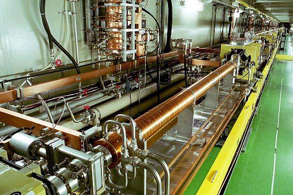
7 TESLA TeV c.m. 33 km X-ray laser e + linear accelerator linear accelerator e - damping ring positron preaccelerator HEP experiments positron source damping ring electron sources
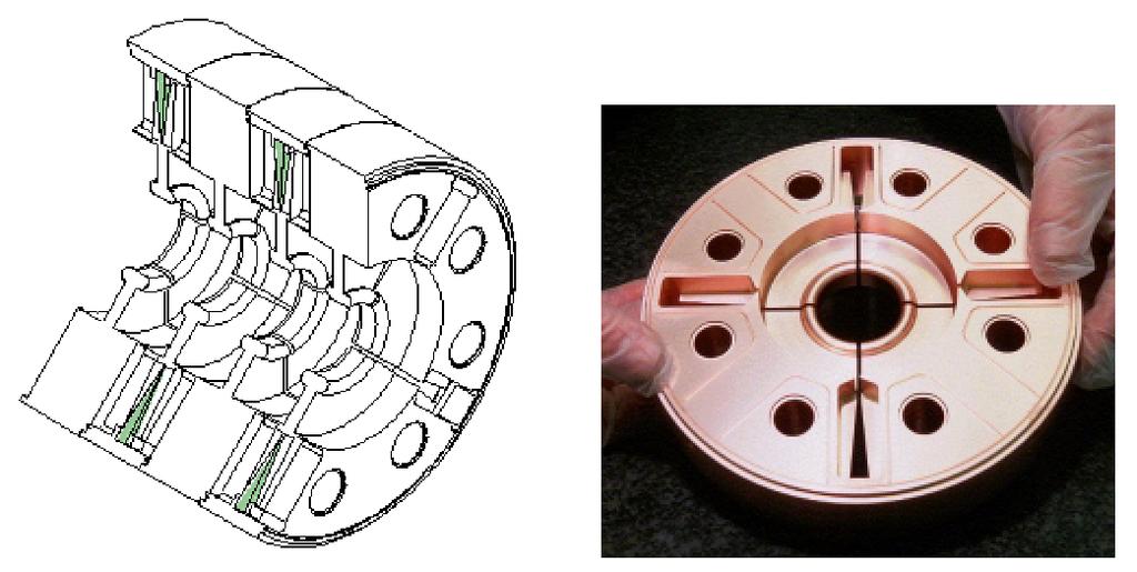
8 CLIC Tapered Damped Structures (TDS) Design criteria: Short & long range wakefields Shunt impedance Operation frequency 30 GHz RF mode 2π / 3 Accelerating Gradient 150 MV/m Iris diameter 2 mm Iris thickness 0.55 mm Alignment tolerances 10 µm Four waveguides with SiC loads guarantee heavy local damping Field limitations due to electrical breakdown and related surface damage required changes in the TDS design. Just recently 150 MV/m peak unloaded gradient were reached in a low group velocity structure with tungsten irises. Testing was limited by rf power source pulse length: 15 ns instead of the required 130 ns. Damping and detuning (1st dipole passband) methods at 30 GHz under study.

 Made with Class 1 OFE Copper.")

9 NLC Next Linear Collider NLC / JLC Rounded Damped-Detuned Structure (RDDS) Operation frequency 11.4 GHz RF mode 2π / 3 Accelerating Gradient 70 MV/m Iris diameter mm RF Input Beam RDDS Cutaway View (8 of 206 cells) HOM Manifold Accerator Cell (Iris diam mm) Made with Class 1 OFE Copper. Cells are precision machined (few µm tolerances) and diffusion bonded to form structures. Fill time attenuation time 100 ns, i.e. length 1.8 m. Operated at 45ºC with water cooling. RF losses approx. 3 kw/m RF ramped during filling to compensate beam loading (21%). In steady state approx. 50% input power goes into the beam.

10 NLC Next Linear Collider Design criteria: Travelling wave structures Disc loaded design Iris surface roughly constant Gradient profile shaped by varying RF group velocity RF time structure influenced by RF attenuation Result: 206 cells, 1.8 m overall length 12% 3% group velocity 70 MV/m, i.e. cost minimum But breakdown related damage!!!
11 NLC Next Linear Collider Surface damage problems An unexpected problem... During conditioning of the first long NLC structures changes in the field profile were observed. A careful inspection has shown - surface damage due to field emission - crater with approx. 30 µm diameter are covering a few percent of the surface - after 1000 h high power operation a 20 deg. phase error was measured at the input coupler s structure end; no error at the other end of the structure - previously built short structures had no problems A possible explanation... Field emission / breakdown cause an RF power absorption being proportional to the group velocity squared. For long structures the group velocity is much higher at the input coupler. before 1000 h of high power operation Bead -pull measurement of the DS2 phase profile after 1000 h of high power operation C. Adolphson et al., RF Processing of X-Band Accelerator Structures at the NLCTA, LINAC 2000 Conference Remark: π-mode standing wave structures have v g 0.

12 High Gradient Structures Goal: 70 MV/m unloaded for 0.5 & 1 TeV Compare performance versus different initial structure group velocity and length cell machining and cleaning methods structure type: traveling wave vs. standing wave 12 structures (5000 h at 60 Hz) processed so far Systematic study of rf breakdown measure breakdown related RF light sound X-rays current gas measure surface roughness / cleanliness / damage with SEM, EDX, XPS and AES Improve structure handling and cleaning methods 53 cm Traveling-Wave Structure Group velocity 3.3% 1.6% c
13 Superconducting Accelerating Structures for TESLA Goal during past decade Increase cavity gradient from 5 to 25 MV/m Reduce costs by a comparable factor 1256 mm 1036 mm mm HOM coupler power coupler Common effort of almost all laboratories using s.c. accelerating cavities, e.g. (CERN), Cornell, DESY, INFN, (KEK), Saclay, TJNL 35 partners from 11 countries rf pick up HOM coupler Improved material quality check New cavity preparation procedures 1400 ºC annealing with a titanium getter ultra-pure, high pressure water rinsing high peak power processing One standard 9-cell TESLA accelerating structure operated as a π-mode standing-wave cavity. One 230 kw rf input coupler, an rf pick up antenna and two Higher Order Mode antennas are assembled to each cavity.


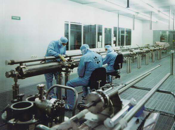
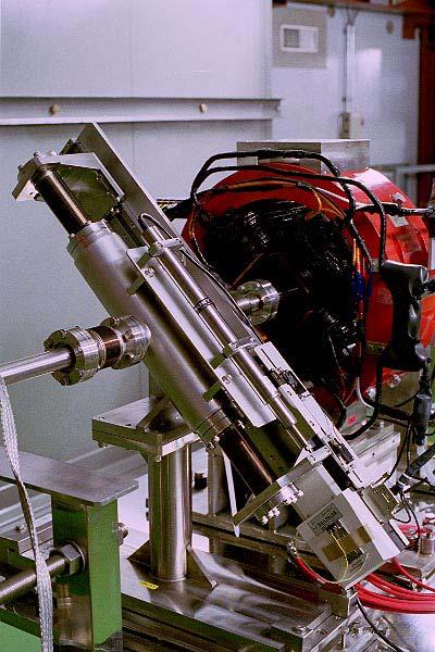
14 Preparation of TESLA Cavities
15 TESLA Cavities Made with solid, pure (RRR >300, high thermal cond.) Niobium Nb sheets are deep-drawn to make cups ( 100 µm tolerances), which are electron beam welded to form structures. Fill time 420 µs, i.e. Q ext =Q beam 3 x 10 6, f 400 Hz RF pulse length (400 µs filling µs flat top) = 1320 µs. Operated at 2 K in superfluid Helium bath. RF losses approx. 1 W/m. RF amplitude and phase adjusted during filling and flat top to compensate beam loading. In steady state essentially 100% rf input power goes into the beam. Q f o = 2π 1 frequency f Q o = = f quality factor f 1Hz LC G R s f 0 = 1,300,000,000 Hz L C f R s
16 High Gradient Performance Unloaded Quality Factor Q 0 Exciation Curves for Cavities from the 3 rd Production Series TESLA goal TESLA goal TESLA goal The First Three Production Series TESLA goal Accelerating Gradient ( MV/m ) Approx. 70 cavities were produced in three production series. Gradient and gradient spread improved a lot. Five accelerator modules with 8 cavities each were assembled. Three of them were used in the TTF Linac. Modules 4 and 5 are going to be tested in early spring The First Five Accelerator Modules

 Unloaded Quality Factor Q 0 Excitation Curves for Cavities from the 3 rd Production Series TESLA goal TESLA goal Unloaded Quality Factor Q 0 First TESLA")
17 35 MV/m for 800 GeV c.m. Electro-polishing (EP) instead of the standard chemical polishing (BCP) eliminates grain boundary steps. First electro-polished single cell cavities Gradients of 40 MV/m at Q values above are now reliably achieved in single 0.5 mm cells at KEK, DESY/CERN and TJNAF. 0.5 mm BCP Surface (1µm roughness) The highest gradient achieved was 42 MV/m. EP Surface (0.1µm roughness) Unloaded Quality Factor Q 0 Excitation Curves for Cavities from the 3 rd Production Series TESLA goal TESLA goal Unloaded Quality Factor Q 0 First TESLA 9-cell cavity above 35 MV/m TESLA 800 goal TESLA 800 goal Accelerating Gradient ( MV/m ) Accelerating Gradient ( MV/m )
18 TESLA Cavity Operation The maximum operating gradient of s.c. cavities is set by cavity quench, field emission, or Q-degradation not by structure breakdown is not a hard limit. It results in high cryogenic load, radiation, and dark current does not trip off cavities in ns but in typ. 100 µs if cavities are operated at the threshold During operation at the TESLA Test Facility Linac it was demonstrated that the trip threshold can be determined easily. An exception handler as part of the LLRF can avoid quenches. Action can be taken prior to the next pulse. High Gradient long pulse run in spring 2002 stable beam operation at 21.5 MV/m (5% below limit) beam energy 195 MeV, beam current 5 ma, 800 µs Accelerator module 39 days at 19.5 MV/m, 800 µs, 5 Hz 4 days at 20.0 MV/m, 800 µs, 1 Hz 6 days at 21.5 MV/m, 800 µs, 1 Hz typ. module on-time 90% Cavities in module 3 (limit at 22.7 MV/m) were operated for approx. 10,000 hours w/o any degradation. 10,000 hours 50% of the time at 800 µs Mostly MV/m 1 Hz rep.rate, during FEL operation

19 NLC vs. TESLA Efficiencies & Power LLRF Klystron 55% RF Distribution 85% Modulator 80% NLC: 10% 13 MW Cryogenics 20 MW Other 8 MW AC-to-Beam Efficiency 139 MW Cooling 15 MW Other 3 MW TESLA 24% Modulator 85% 97 MW 23 MW RF Distribution 94% Klystron 65% LLRF
20 NLC Linac RF Unit Low Level RF System (not shown) One 490 kv 3-Turn Induction Modulator Eight 3 kw TWT Klystron Drivers (not shown) Eight 75 MW PPM Klystrons Delay Line Distribution System (2 Mode, 4 Lines) Eight Accelerator Structure Sextets


21 NLC Induction Modulator Prototype 10 core test 22 kv, 6 ka, 3µs Klystron (5045 for testing) Water Load MetGlas Cores Capacitors IGBTs 10 cm Driver Circuit


22 NLC XP-Klystron Program 50 MW Solenoid Focused Tubes were built for testing Solenoid Power = 25 kw Periodic Permanent Magnet focusing is used for XP type klystrons. The first tube finally reached 70 MW, 3.1 µs, limited by the modulator. The next generation tubes are still not performing well. Eight tubes in total are needed for the 8-pack test with DLDS and accel.structures (scheduled for mid 2004).

23 JLC PPM Klystron Program KEK with Toshiba have built a 75 MW, 1.5 µs tube (PPM-2) which basically meets the JLC design goals. PPM-2 Peak Power Efficiency Puls Width Repetition rate Design 75 MW 55% 1.5 µs 150 Hz Achieved 75.1 MW 56% 1.4 µs at 74 MW 1.5 µs at 70 W 25 Hz New tubes with 60% efficiency (PPM-3) and easier manufacturability (PPM-4) are foreseen.


24 NLC DLDS System Feeding of six structures RF Power Distribution incl. Pulse-Compression from 75 MW / 3.2 µs to 600 MW / 0.4 µs mid 2004
25 TESLA RF Unit 1 klystron for 3 accelerating modules, 12 nine-cell cavities each vector modulator MBK Klystron DAC DAC Low Level RF System circulator stub tuner (phase & Qext) coaxial coupler Mechanical tuner (frequency adj.) and piezo-electric tuner (Lorentz force compensation) cavity #1 cavity #12 vector sum pickup signal ADC ADC accelerator module 1 of 3 vector demodulator

 Switches instead of IGBT or")

26 TESLA Modulator Based on good experience with three FNAL Bouncer Type Modulators the next generation features A constant power High Voltage Power Supply Matching to TH2104C (5 MW) and TH1801 (10 MW MBK) Integrated Gate Commutated Thyristor (IGCT) Switches instead of IGBT or GTO Technology A Lower Leakage Inductance Pulse Transformer Partially manufactured in industry IGCT Stack HV Power Supply Capacitor Bank Bouncer Pulse Transformer


27 TESLA Multi Beam Klystrons MBKs reduce HV requirements and improve the efficiency because of lower space charge. Seven beams, 18.6 A, 110 kv, produce 10 MW with 70% eff. Three Thales TH1801 Multi Beam Klystrons were produced. Achieved efficiency 65% RF pulse width Repetition rate Operation experience 1.5 ms 5 Hz > 5000 h Approx. 10% of operation time at full spec s
28 CLIC Test Facility CTF3

29 JLC Japan Linear Collider Accelerator Test Facility


30 JLC Japan Linear Collider Cavity Production Damping Ring Wire-Scanner S-Band Linac Wiggler-Magnet
31 NLC Test Accelerator (NLCTA) Goals: RF system integration test of a NLC linac section test efficient, stable and uniform acceleration of a NLC-like bunch train Construction started in 1993 using first generation RF component design. In 1997, 15% beam loading compensation of a 120 ns bunch train to <0.3% was demonstrated. klystron SLED II pulse compression X 4 3db hybrid 40 m resonant delay lines beam accelerating structures


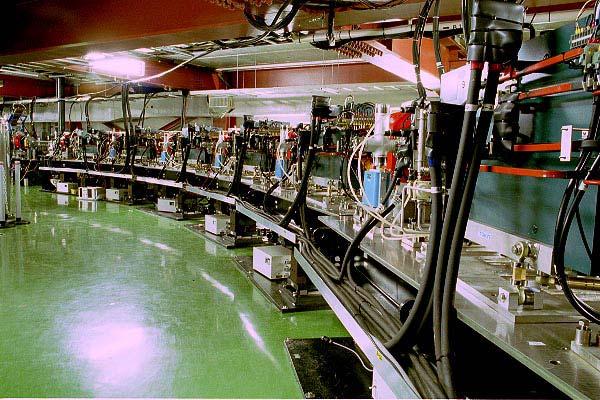
32 TESLA Test Facility Linac e - beam diagnostics undulator bunch compressor e - beam diagnostics laser driven electron gun photon beam diagnostics superconducting accelerator modules preaccelerator 250 MeV 120 MeV 16 MeV 4 MeV

33 TESLA Test Facility - Operation The TTF Linac is operated 7 days per week, 24 hours. Approx. 50% of the time is allocated to FEL operation including a large percentage of user time. The FEL requires very stable beam conditions. In its different set-ups, approx. 13,000 hours beamtime were achieved since Based of the TTF experience several FELs using superconducting accelerator technology are proposed. DOWN 8% OFF 6% DOWN 6% OFF 8% USERS 0% Beam uptime and operational uptime (users or acc.studies) TUNING 19% TUNING 25% 100% STUDIES 4% USERS 63% STUDIES 61% 80% 60% week 3 / 2002 week 7 / % 20% FEL User Operation Accelerator Studies week


34 TESLA Test Facility Linac Phase II FEL User Facility in the nm Wavelength Range Six accelerator modules to reach 1 GeV beam energy. Module #6 will contain 8 electro-polished cavities. Engineering with respect to TESLA needs. Klystrons and modulators build in industry. High gradient operation of accelerator modules. Space for module #7 (12 cavity TESLA module). Commissioning RF in spring 2003 FEL in fall 2003 experimental area bypass 1000 MeV 450 MeV 150 MeV BC 3 BC 2 4MeV undulators seeding collimator #7 #6 #5 #4 #3 #2 module #1 RF gun 250 m
35 TESLA R&D Schedule Structures long-term operation at full 500 GeV c.m.specs. module 1* at 25 MV/m 7 10 / 02 module 4 & 5 above 25 MV/m (rf test) 3 5 / 03 high gradient 35 MV/m tests for 800 GeV c.m. ongoing one complete module in Power Sources testing HV cables 2003 lifetime MBK (multi-beam klystron) on hold Power distribution circulators for upgrade to 800 GeV c.m. ongoing Injectors, Damping Rings etc. laser R&D for polarized source ongoing kicker magnets & pulser ongoing, instrumentation (identical to all LC projects) ongoing
36 NLC R&D Schedule Structures study break down damage ongoing build final NLC structure long-term testing of final NLC structure 2004 Power Sources build 3 x XP-3 klystron 2002 test 2-pack + SLED II 2003 build 6 x XP test 8-pack incl. MDLDS etc. plus 6 Acc.Structures 2004 Power distribution SLED II test 2003 MDLDS test mid 2004 Injectors, Damping Rings etc. conventional e+ source undulator e+ source instrumentation (identical to all LC projects) BDS crab crossing on hold proposed ongoing on hold
37 Summary CTF3 in 2006 ILC-TRC Report in 12/ pack test mid 2004 TESLA 500 now 35 MV/m to be tested in 2003 / 2004
The TESLA Linear Collider. Winfried Decking (DESY) for the TESLA Collaboration
 for the TESLA Collaboration") The TESLA Linear Collider Winfried Decking (DESY) for the TESLA Collaboration Outline Project Overview Highlights 2000/2001 Publication of the TDR Cavity R&D TTF Operation A0 and PITZ TESLA Beam Dynamics
The TESLA Linear Collider Winfried Decking (DESY) for the TESLA Collaboration Outline Project Overview Highlights 2000/2001 Publication of the TDR Cavity R&D TTF Operation A0 and PITZ TESLA Beam Dynamics
International Technology Recommendation Panel. X-Band Linear Collider Path to the Future. RF System Overview. Chris Adolphsen
 International Technology Recommendation Panel X-Band Linear Collider Path to the Future RF System Overview Chris Adolphsen Stanford Linear Accelerator Center April 26-27, 2004 Delivering the Beam Energy
X-Band Linear Collider Report*
 SLAC DOE Program Review X-Band Linear Collider Path to the Future X-Band Linear Collider Report* D. L. Burke NLC Program Director * Abstracted from recent presentations to the International Technical Recommendation
TESLA TeV Collider Project Overview
 Hamburg-Zeuthen Linear Collider Meeting TESLA TeV Collider Project Overview Carlo Pagani Milano & DESY carlo.pagani@desy.de The TESLA Challenge Physical limit is 50 MV/m > 25 MV/m could be obtained Common
Demonstration of exponential growth and saturation at VUV wavelengths at the TESLA Test Facility Free-Electron Laser. P. Castro for the TTF-FEL team
 Demonstration of exponential growth and saturation at VUV wavelengths at the TESLA Test Facility Free-Electron Laser P. Castro for the TTF-FEL team 100 nm 1 Å FEL radiation TESLA Test Facility at DESY
NLC - The Next Linear Collider Project. NLC Update. CLIC Group. CERN September D. L. Burke SLAC
 NLC Update CLIC Group September 2003 SLAC Configuration Electron Injector 560 m ~10 m 170 m Pre-Linac 6 GeV (S) Compressor 136 MeV (L) 2 GeV (S) ~100 m 0.6 GeV (X) ~20 m Compressor Damping Ring e (UHF)
TESLA Progress on R1 & R2 issues
 TESLA Progress on R1 & R2 issues Carlo Pagani Milano & DESY carlo.pagani@desy.de The TESLA Challenge for LC Physical limit at 50 MV/m > 25 MV/m could be obtained Common R&D effort for TESLA Higher conversion
Low-Level RF. S. Simrock, DESY. MAC mtg, May 05 Stefan Simrock DESY
 Low-Level RF S. Simrock, DESY Outline Scope of LLRF System Work Breakdown for XFEL LLRF Design for the VUV-FEL Cost, Personpower and Schedule RF Systems for XFEL RF Gun Injector 3rd harmonic cavity Main
H. Weise, Deutsches Elektronen-Synchrotron, Hamburg, Germany for the XFEL Group
 7+(7(6/$;)(/352-(&7 H. Weise, Deutsches Elektronen-Synchrotron, Hamburg, Germany for the XFEL Group $EVWUDFW The overall layout of the X-Ray FEL to be built in international collaboration at DESY will
FLASH at DESY. FLASH. Free-Electron Laser in Hamburg. The first soft X-ray FEL operating two undulator beamlines simultaneously
 FLASH at DESY The first soft X-ray FEL operating two undulator beamlines simultaneously Katja Honkavaara, DESY for the FLASH team FEL Conference 2014, Basel 25-29 August, 2014 First Lasing FLASH2 > First
Status of Warm-Cold Linear Collider Competition
 Status of Warm-Cold Linear Collider Competition Nick Walker (DESY) SRF 2003 Travemünde 12.09.2003 What s in Store? Pedestrians Guide to e + e - linear colliders The Findings of the 2 nd International Linear
Cavity development for TESLA
 Cavity development for TESLA Lutz.Lilje@desy.de DESY -FDET- Cavity basics History: Limitations and solutions»material inclusions»weld defects»field emission»increased surface resistance at high field Performance
Normal-conducting high-gradient rf systems
 Normal-conducting high-gradient rf systems Introduction Motivation for high gradient Order of 100 GeV/km Operational and state-of-the-art SwissFEL C-band linac: Just under 30 MV/m CLIC prototypes: Over
Superstructures; First Cold Test and Future Applications
 Superstructures; First Cold Test and Future Applications DESY: C. Albrecht, V. Ayvazyan, R. Bandelmann, T. Büttner, P. Castro, S. Choroba, J. Eschke, B. Faatz, A. Gössel, K. Honkavaara, B. Horst, J. Iversen,
Present Status of R&D for the Superconducting Linac
 International Conference on Linear Colliders Colloque international sur les collisionneurs linéaires LCWS 04 : 19-23 April 2004 - "Le Carré des Sciences", Paris, France Present Status of R&D for the Superconducting
FAST RF KICKER DESIGN
 FAST RF KICKER DESIGN David Alesini LNF-INFN, Frascati, Rome, Italy ICFA Mini-Workshop on Deflecting/Crabbing Cavity Applications in Accelerators, Shanghai, April 23-25, 2008 FAST STRIPLINE INJECTION KICKERS
HIGH POWER COUPLER FOR THE TESLA TEST FACILITY
 Abstract HIGH POWER COUPLER FOR THE TESLA TEST FACILITY W.-D. Moeller * for the TESLA Collaboration, Deutsches Elektronen-Synchrotron DESY, D-22603 Hamburg, Germany The TeV Energy Superconducting Linear
THE CRYOGENIC SYSTEM OF TESLA
 THE CRYOGENIC SYSTEM OF TESLA S. Wolff, DESY, Notkestr. 85, 22607 Hamburg, Germany for the TESLA collaboration Abstract TESLA, a 33 km long 500 GeV centre-of-mass energy superconducting linear collider
High Gradient Studies at the NLC Test Accelerator (NLCTA)
") Chris Adolphsen High Gradient Studies at the NLC Test Accelerator (NLCTA) NLCTA Linac RF Unit (One of Two) Contributors C. Adolphsen, G. Bowden, D. Burke, J. Cornuelle, S. Dobert, V. Dolgashev, J. Frisch,
Chris Adolphsen High Gradient Studies at the NLC Test Accelerator (NLCTA) NLCTA Linac RF Unit (One of Two) Contributors C. Adolphsen, G. Bowden, D. Burke, J. Cornuelle, S. Dobert, V. Dolgashev, J. Frisch,
RF STATUS OF SUPERCONDUCTING MODULE DEVELOPMENT SUITABLE FOR CW OPERATION: ELBE CRYOSTATS
 RF STATUS OF SUPERCONDUCTING MODULE DEVELOPMENT SUITABLE FOR CW OPERATION: ELBE CRYOSTATS J. Teichert, A. Büchner, H. Büttig, F. Gabriel, P. Michel, K. Möller, U. Lehnert, Ch. Schneider, J. Stephan, A.
Using Higher Order Modes in the Superconducting TESLA Cavities for Diagnostics at DESY
 Using Higher Order Modes in the Superconducting TESLA Cavities for Diagnostics at FLASH @ DESY N. Baboi, DESY, Hamburg for the HOM team : S. Molloy 1, N. Baboi 2, N. Eddy 3, J. Frisch 1, L. Hendrickson
ALICE SRF SYSTEM COMMISSIONING EXPERIENCE A. Wheelhouse ASTeC, STFC Daresbury Laboratory
 ALICE SRF SYSTEM COMMISSIONING EXPERIENCE A. Wheelhouse ASTeC, STFC Daresbury Laboratory ERL 09 8 th 12 th June 2009 ALICE Accelerators and Lasers In Combined Experiments Brief Description ALICE Superconducting
Experience with 3.9 GHz cavity HOM couplers
 Cornell University, October 11-13, 2010 Experience with 3.9 GHz cavity HOM couplers T. Khabiboulline, N. Solyak, FNAL. 3.9 GHz cavity general parameters Third harmonic cavity (3.9GHz) was proposed to compensate
Overview of ERL Projects: SRF Issues and Challenges. Matthias Liepe Cornell University
 Overview of ERL Projects: SRF Issues and Challenges Matthias Liepe Cornell University Overview of ERL projects: SRF issues and challenges Slide 1 Outline Introduction: SRF for ERLs What makes it special
3 General layout of the XFEL Facility
 3 General layout of the XFEL Facility 3.1 Introduction The present chapter provides an overview of the whole European X-Ray Free-Electron Laser (XFEL) Facility layout, enumerating its main components and
XFEL Cryo System. Project X Collaboration Meeting, FNAL September 8-9, 2010 Bernd Petersen DESY MKS (XFEL WP10 & WP13) 1 st stage. Possible extension
 1 st stage. Possible extension") XFEL Cryo System Possible extension 1 st stage Project X Collaboration Meeting, FNAL September 8-9, 2010 (XFEL WP10 & WP13) Outline 2 XFEL accelerator structure TESLA technology Basic cryogenic parameters
XFEL Cryo System Possible extension 1 st stage Project X Collaboration Meeting, FNAL September 8-9, 2010 (XFEL WP10 & WP13) Outline 2 XFEL accelerator structure TESLA technology Basic cryogenic parameters
The European Spallation Source. Dave McGinnis Chief Engineer ESS\Accelerator Division IVEC 2013
 The European Spallation Source Dave McGinnis Chief Engineer ESS\Accelerator Division IVEC 2013 Overview The European Spallation Source (ESS) will house the most powerful proton linac ever built. The average
Third Harmonic Cavity Status
 Third Harmonic Cavity Status General parameters Cavity design Main coupler calculation HOM analysis and HOM coupler design Lorentz Forces and Stress analysis Summary General parameters Third harmonic cavity
Fabrication Techniques for the X-band Accelerator Structures. Juwen Wang WORKSHOP ON X-BAND RF TECHNOLOGY FOR FELs March 5, 2010
 Fabrication Techniques for the X-band Accelerator Structures Juwen Wang WORKSHOP ON X-BAND RF TECHNOLOGY FOR FELs March 5, 2010 Outline 1. Introduction Brief history Achievements 2. Basics of X-Band Accelerator
RF Design of Normal Conducting Deflecting Cavity
 RF Design of Normal Conducting Deflecting Cavity Valery Dolgashev (SLAC), Geoff Waldschmidt, Ali Nassiri (Argonne National Laboratory, Advanced Photon Source) 48th ICFA Advanced Beam Dynamics Workshop
Behavior of the TTF2 RF Gun with long pulses and high repetition rates
 Behavior of the TTF2 RF Gun with long pulses and high repetition rates J. Baehr 1, I. Bohnet 1, J.-P. Carneiro 2, K. Floettmann 2, J. H. Han 1, M. v. Hartrott 3, M. Krasilnikov 1, O. Krebs 2, D. Lipka
High acceleration gradient. Critical applications: Linear colliders e.g. ILC X-ray FELs e.g. DESY XFEL
 High acceleration gradient Critical applications: Linear colliders e.g. ILC X-ray FELs e.g. DESY XFEL Critical points The physical limitation of a SC resonator is given by the requirement that the RF magnetic
TESLA RF POWER COUPLERS DEVELOPMENT AT DESY.
 TESLA RF POWER COUPLERS DEVELOPMENT AT DESY. Dwersteg B., Kostin D., Lalayan M., Martens C., Möller W.-D., DESY, D-22603 Hamburg, Germany. Abstract Different RF power couplers for the TESLA Test Facility
Maurizio Vretenar Linac4 Project Leader EuCARD-2 Coordinator
 Maurizio Vretenar Linac4 Project Leader EuCARD-2 Coordinator Every accelerator needs a linac as injector to pass the region where the velocity of the particles increases with energy. At high energies (relativity)
Commissioning of the ALICE SRF Systems at Daresbury Laboratory Alan Wheelhouse, ASTeC, STFC Daresbury Laboratory ESLS RF 1 st 2 nd October 2008
 Commissioning of the ALICE SRF Systems at Daresbury Laboratory Alan Wheelhouse, ASTeC, STFC Daresbury Laboratory ESLS RF 1 st 2 nd October 2008 Overview ALICE (Accelerators and Lasers In Combined Experiments)
MuCool Test Area Experimental Program Summary
 MuCool Test Area Experimental Program Summary Alexey Kochemirovskiy The University of Chicago/Fermilab Alexey Kochemirovskiy NuFact'16 (Quy Nhon, August 21-27, 2016) Outline Introduction Motivation MTA
Report of working group 5
 Report of working group 5 Materials Cavity design Cavity Fabrication Preparatioin & Testing Power coupler HOM coupler Beam line absorber Tuner Fundamental R&D items Most important R&D items 500 GeV parameters
C100 Cryomodule. Seven cell Cavity, 0.7 m long (high Q L ) 8 Cavities per Cryomodule Fits the existing Cryomodule footprint
 8 Cavities per Cryomodule Fits the existing Cryomodule footprint") 1 new module C100 Cryomodule Seven cell Cavity, 0.7 m long (high Q L ) 8 Cavities per Cryomodule Fits the existing Cryomodule footprint Fundamental frequency f 0 Accelerating gradient E acc 1497 MHz >
1 new module C100 Cryomodule Seven cell Cavity, 0.7 m long (high Q L ) 8 Cavities per Cryomodule Fits the existing Cryomodule footprint Fundamental frequency f 0 Accelerating gradient E acc 1497 MHz >
The ILC Accelerator Complex
 The ILC Accelerator Complex Nick Walker DESY/GDE UK LC meeting 3 rd September 2013 Oxford University, UK. 1 ILC in a Nutshell 200-500 GeV E cm e + e - collider L ~2 10 34 cm -2 s -1 upgrade: ~1 TeV central
Tuning systems for superconducting cavities at Saclay
 Tuning systems for superconducting cavities at Saclay 1 MACSE: 1990: tuner in LHe bath at 1.8K TTF: 1995 tuner at 1.8K in the insulating vacuum SOLEIL: 1999 tuner at 4 K in the insulating vacuum Super-3HC:
R.Bachimanchi, IPAC, May 2015, Richmond, VA
 1 new module C100 Cryomodule Seven cell Cavity, 0.7 m long (high Q L ) 8 Cavities per Cryomodule Fits the existing Cryomodule footprint Fundamental frequency f 0 Accelerating gradient E acc 1497 MHz >
Superconducting 1.3 GHz Cavities for European XFEL
 Superconducting 1.3 GHz Cavities for European XFEL W. Singer, J. Iversen, A. Matheisen, X. Singer (DESY, Germany) P. Michelato (INFN, Italy) Presented by Waldemar Singer Main issues: preparation phase
Status of the European XFEL Accelerator Construction Project. Reinhard Brinkmann, DESY
 Status of the European XFEL Accelerator Construction Project Reinhard Brinkmann, DESY European XFEL Introduction Some specifications Photon energy 0.3-24 kev Pulse duration ~ 10-100 fs Pulse energy few
Performance of Superconducting Cavities for the European XFEL. Detlef Reschke DESY for the EU-XFEL Accelerator Consortium
 Performance of Superconducting Cavities for the European XFEL Detlef Reschke DESY for the EU-XFEL Accelerator Consortium Outline 2 European XFEL Linear Accelerator Cavity Production Vertical Acceptance
Physics Requirements Document Document Title: SCRF 1.3 GHz Cryomodule Document Number: LCLSII-4.1-PR-0146-R0 Page 1 of 7
 Document Number: LCLSII-4.1-PR-0146-R0 Page 1 of 7 Document Approval: Originator: Tor Raubenheimer, Physics Support Lead Date Approved Approver: Marc Ross, Cryogenic System Manager Approver: Jose Chan,
Room Temperature High Repetition Rate RF Structures for Light Sources
 Room Temperature High Repetition Rate RF Structures for Light Sources Sami G. Tantawi SLAC Claudio Pellegrini, R. Ruth, J. Wang. V. Dolgashev, C. Bane, Zhirong Huang, Jeff Neilson, Z. Li Outline Motivation
Project X Cavity RF and mechanical design. T. Khabiboulline, FNAL/TD/SRF
 Project X Cavity RF and mechanical design T. Khabiboulline, FNAL/TD/SRF TTC meeting on CW-SRF, 2013 Project X Cavity RF and mechanical design T 1 High ß Low ß 0.5 HWR SSR1 SSR2 0 1 10 100 1 10 3 1 10 4
High Power Couplers for TTF - FEL
 High Power Couplers for TTF - FEL 1. Requirements for High Power Couplers on superconducting Cavities 2. Characteristics of pulsed couplers 3. Standing wave pattern in the coaxial coupler line 4. Advantages
Progress in High Gradient Accelerator Research at MIT
 Progress in High Gradient Accelerator Research at MIT Presented by Richard Temkin MIT Physics and Plasma Science and Fusion Center May 23, 2007 MIT Accelerator Research Collaborators MIT Plasma Science
SwissFEL Design and Status
 SwissFEL Design and Status Hans H. Braun Mini Workshop on Compact X ray Free electron Lasers Eastern Forum of Science and Technology Shanghai July 19, 2010 SwissFEL, the next large facility at PSI SwissFEL
CLIC Compact Linear Collider
 f1 CLIC Compact LInear Collider Frank Zimmermann for the CLIC Study Team many CLIC contributors! special thanks to Hans Braun, Jean-Pierre Delahaye, & Frank Tecker! Frank Zimmermann UPHUK3 2007, Bodrumr,
DEVELOPMENT OF A BETA 0.12, 88 MHZ, QUARTER WAVE RESONATOR AND ITS CRYOMODULE FOR THE SPIRAL2 PROJECT
 DEVELOPMENT OF A BETA 0.12, 88 MHZ, QUARTER WAVE RESONATOR AND ITS CRYOMODULE FOR THE SPIRAL2 PROJECT G. Olry, J-L. Biarrotte, S. Blivet, S. Bousson, C. Commeaux, C. Joly, T. Junquera, J. Lesrel, E. Roy,
Beam Diagnostics, Low Level RF and Feedback for Room Temperature FELs. Josef Frisch Pohang, March 14, 2011
 Beam Diagnostics, Low Level RF and Feedback for Room Temperature FELs Josef Frisch Pohang, March 14, 2011 Room Temperature / Superconducting Very different pulse structures RT: single bunch or short bursts
Advance on High Power Couplers for SC Accelerators
 Advance on High Power Couplers for SC Accelerators Eiji Kako (KEK, Japan) IAS conference at Hong Kong for High Energy Physics, 2017, January 23th Eiji KAKO (KEK, Japan) IAS at Hong Kong, 2017 Jan. 23 1
FLASH Operation at DESY From a Test Accelerator to a User Facility
 FLASH Operation at DESY From a Test Accelerator to a User Facility Michael Bieler FLASH Operation at DESY WAO2012, SLAC, Aug. 8, 2012 Vocabulary DESY: Deutsches Elektronen-Synchrotron, Hamburg, Germany
FLASH. FLASH Training: RF Gun. FLASH: the first soft X-ray FEL operating two undulator beamlines simultaneously. Siegfried Schreiber, DESY
 FLASH Training: RF Gun FLASH: the first soft X-ray FEL operating two undulator beamlines simultaneously Siegfried Schreiber, DESY FLASH Training DESY 17-Mar-2017 FLASH1 RF Gun History RF Guns operated
Engineering Challenges and Solutions for MeRHIC. Andrew Burrill for the MeRHIC Team
 Engineering Challenges and Solutions for MeRHIC Andrew Burrill for the MeRHIC Team Key Components Photoinjector Design Photocathodes & Drive Laser Linac Cavities 703.75 MHz 5 cell cavities 3 rd Harmonic
Grounding for EMC at the European XFEL
 Grounding for EMC at the European XFEL Herbert Kapitza, Hans-Jörg Eckoldt, Markus Faesing Deutsches Elektronensynchrotron (DESY) D-22603 Hamburg, Germany Email: herbert.kapitza@desy.de Abstract The European
Attosecond Diagnostics of Muti GeV Electron Beams Using W Band Deflectors
 Attosecond Diagnostics of Muti GeV Electron Beams Using W Band Deflectors V.A. Dolgashev, P. Emma, M. Dal Forno, A. Novokhatski, S. Weathersby SLAC National Accelerator Laboratory FEIS 2: Femtosecond Electron
Current Industrial SRF Capabilities and Future Plans
 and Future Plans Capabilities in view of Design Engineering Manufacturing Preparation Testing Assembly Taking into operation Future Plans Participate in and contribute to development issues, provide prototypes
INSTALLATION AND FIRST COMMISSIONING OF THE LLRF SYSTEM
 INSTALLATION AND FIRST COMMISSIONING OF THE LLRF SYSTEM FOR THE EUROPEAN XFEL Julien Branlard, for the LLRF team TALK OVERVIEW 2 Introduction Brief reminder about the XFEL LLRF system Commissioning goals
Status of superconducting module development suitable for cw operation: ELBE cryostats
 Status of superconducting module development suitable for cw operation: ELBE cryostats, A. Büchner, H. Büttig, F. Gabriel, P. Michel, K. Möller, U. Lehnert, Ch. Schneider, J. Stephan, A. Winter Forschungszentrum
SNS LLRF Design Experience and its Possible Adoption for the ILC
 SNS LLRF Design Experience and its Possible Adoption for the ILC Brian Chase SNS - Mark Champion Fermilab International Linear Collider Workshop 11/28/2005 1 Why Consider the SNS System for ILC R&D at
Message from the Americas
 Message from the Americas G. Dugan, Cornell Univ. for the United States Linear Collider Steering Group (USLCSG) First ILC Workshop KEK, Tsukuba, Japan Nov. 13, 2004 Outline Perspectives on the ILC from
5.5 SNS Superconducting Linac
 JP0150514 ICANS - XV 15 th Meeting of the International Collaboration on Advanced Neutron Sources November 6-9, 2000 Tsukuba, Japan Ronald M. Sundelin Jefferson Lab* 5.5 SNS Superconducting Linac 12000
THE HIGH LUMINOSITY PERFORMANCE OF CESR WITH THE NEW GENERATION SUPERCONDUCTING CAVITY
 Presented at the 1999 Particle Accelerator Conference, New York City, NY, USA, March 29 April 2 CLNS 99/1614 / SRF 990407-03 THE HIGH LUMINOSITY PERFORMANCE OF CESR WITH THE NEW GENERATION SUPERCONDUCTING
LLRF Operation and Performance of the European XFEL. An overview
 LLRF Operation and Performance of the European XFEL. An overview Mathieu Omet LLRF, Barcelona, 16.10.2017 Contents > Introduction > LLRF commissioning > Energy Reach > LLRF performance > Summary / Outlook
ERLP Status. Mike Dykes
 ERLP Status Mike Dykes Content ASTeC RF & Diagnostics Group Work of the Group 4GLS ERLP Photo-injector Accelerating Modules Summary High Power RF Engineering Andy Moss SRS Support; DIAMOND; ERLP; MICE;
HIGH POWER INPUT COUPLERS FOR THE STF BASELINE CAVITY SYSTEM AT KEK
 HIGH POWER INPUT COUPLERS FOR THE STF BASELINE CAVITY SYSTEM AT KEK E. Kako #, H. Hayano, S. Noguchi, T. Shishido, K. Watanabe and Y. Yamamoto KEK, Tsukuba, Ibaraki, 305-0801, Japan Abstract An input coupler,
REVIEW OF HIGH POWER CW COUPLERS FOR SC CAVITIES. S. Belomestnykh
 REVIEW OF HIGH POWER CW COUPLERS FOR SC CAVITIES S. Belomestnykh HPC workshop JLAB, 30 October 2002 Introduction Many aspects of the high-power coupler design, fabrication, preparation, conditioning, integration
LLRF Plans for SMTF. Ruben Carcagno (Fermilab) Nigel Lockyer (University of Pennsylvania) Thanks to DESY, PISA, KEK, Fermilab, SLAC Colleagues
 Nigel Lockyer (University of Pennsylvania) Thanks to DESY, PISA, KEK, Fermilab, SLAC Colleagues") LLRF Plans for SMTF Ruben Carcagno (Fermilab) Nigel Lockyer (University of Pennsylvania) Thanks to DESY, PISA, KEK, Fermilab, SLAC Colleagues Outline Near-term (< 1.5 years) SMTF LLRF plan Long-term (>
LLRF Plans for SMTF Ruben Carcagno (Fermilab) Nigel Lockyer (University of Pennsylvania) Thanks to DESY, PISA, KEK, Fermilab, SLAC Colleagues Outline Near-term (< 1.5 years) SMTF LLRF plan Long-term (>
Performance of the TTF Photoinjector Laser System
 Performance of the TTF Photoinjector Laser System S. Schreiber, DESY Laser Issues for Electron Photoinjectors, October 23-25, 22, Stanford, California, USA & I. Will, A. Liero, W. Sandner, MBI Berlin Overview
Does the short pulse mode need energy recovery?
 Does the short pulse mode need energy recovery? Rep. rate Beam power @ 5GeV 1nC @ 100MHz 500MW Absolutely 1nC @ 10MHz 1nC @ 1MHz 50MW 5MW Maybe 1nC @ 100kHz 0.5MW No Most applications we have heard about
Design considerations for the RF phase reference distribution system for X-ray FEL and TESLA
 Design considerations for the RF phase reference distribution system for X-ray FEL and TESLA Krzysztof Czuba *a, Henning C. Weddig #b a Institute of Electronic Systems, Warsaw University of Technology,
STATUS OF THE RF SUPERCONDUCTIVITY ACTIVITIES AT DESY
 STATUS OF THE RF SUPERCONDUCTIVITY ACTIVITIES AT DESY Axel Matheisen** Deutsches Elektronen-Synchrotron DESY Notkestraße 85, D 22607 Hamburg, Germany for the TESLA collaboration* Abstract At DESY one major
TECHNICAL CHALLENGES OF THE LCLS-II CW X-RAY FEL *
 TECHNICAL CHALLENGES OF THE LCLS-II CW X-RAY FEL * T.O. Raubenheimer # for the LCLS-II Collaboration, SLAC, Menlo Park, CA 94025, USA Abstract The LCLS-II will be a CW X-ray FEL upgrade to the existing
Calibrating the Cavity Voltage. Presentation of an idea
 Calibrating the Cavity Voltage. Presentation of an idea Stefan Wilke, DESY MHF-e 21st ESLS rf meeting Kraków, 15th/16th nov 2017 Accelerators at DESY. linear and circular Page 2 Accelerators at DESY. linear
2 Results of Superconducting Accelerator Development
 II-19 2 Results of Superconducting Accelerator Development 2.1 Superconducting Cavities 2.1.1 Introduction Historically, the main drawback of superconducting (sc) accelerating structures has been the low
RF Cavity Design. Erk Jensen CERN BE/RF. CERN Accelerator School Accelerator Physics (Intermediate level) Darmstadt 2009
 Darmstadt 2009") RF Cavity Design Erk Jensen CERN BE/RF CERN Accelerator School Accelerator Physics (Intermediate level) Darmstadt 009 CAS Darmstadt '09 RF Cavity Design 1 Overview DC versus RF Basic equations: Lorentz
RF Cavity Design Erk Jensen CERN BE/RF CERN Accelerator School Accelerator Physics (Intermediate level) Darmstadt 009 CAS Darmstadt '09 RF Cavity Design 1 Overview DC versus RF Basic equations: Lorentz
CHALLENGES IN ILC SCRF TECHNOLOGY *
 CHALLENGES IN ILC SCRF TECHNOLOGY * Detlef Reschke #, DESY, D-22603 Hamburg, Germany Abstract With a baseline operating gradient of 31,5 MV/m at a Q-value of 10 10 the superconducting nine-cell cavities
Design and RF Measurements of an X-band Accelerating Structure for the Sparc Project
 Design and RF Measurements of an X-band Accelerating Structure for the Sparc Project INFN-LNF ; UNIVERSITY OF ROME LA SAPIENZA ; INFN - MI Presented by BRUNO SPATARO Erice, Sicily, October 9-14; 2005 SALAF
SOLID-STATE SWITCHING MODULATOR R&D FOR KLYSTRON
 SOLID-STATE SWITCHING MODULATOR R&D FOR KLYSTRON M. Akemoto High Energy Accelerator Research Organization (KEK), Tsukuba, Japan Abstract KEK has two programs to improve reliability, energy efficiency and
HIGH POWER PULSED TESTS OF A BETA=0.5 5-CELL 704 MHZ SUPERCONDUCTING CAVITY
 HIGH POWER PULSED TESTS OF A BETA=0.5 5-CELL 704 MHZ SUPERCONDUCTING CAVITY G. Devanz, D. Braud, M. Desmons, Y. Gasser, E. Jacques, O. Piquet, J. Plouin, J.- P. Poupeau, D. Roudier, P. Sahuquet, CEA-Saclay,
Acceleration of High-Intensity Protons in the J-PARC Synchrotrons. KEK/J-PARC M. Yoshii
 Acceleration of High-Intensity Protons in the J-PARC Synchrotrons KEK/J-PARC M. Yoshii Introduction 1. J-PARC consists of 400 MeV Linac, 3 GeV Rapid Cycling Synchrotron (RCS) and 50 GeV Main synchrotron
THE TRANSFORMATION OF THE TESLA TEST FACILITY INTO THE VUV FEL USER FACILITY AT DESY
 THE TRANSFORMATION OF THE TESLA TEST FACILITY INTO THE VUV FEL USER FACILITY AT DESY Abstract A. Gamp, Deutsches Elektronensynchrotron DESY, D22670, Hamburg for the TESLA Collaboration* After the end of
EXPERIMENTAL RESULT OF LORENTZ DETUNING IN STF PHASE-1 AT KEK-STF
 EXPERIMENTAL RESULT OF LORENTZ DETUNING IN STF PHASE-1 AT KEK-STF Y. Yamamoto #, H. Hayano, E. Kako, T. Matsumoto, S. Michizono, T. Miura, S. Noguchi, M. Satoh, T. Shishidio, K. Watanabe, KEK, Tsukuba,
Drive Beam Photo-injector Option for the CTF3 Nominal Phase
 CTF3 Review Drive Beam Photo-injector Option for the CTF3 Nominal Phase Motivation CTF3 Drive Beam Requirements CTF3 RF gun design The Laser (I. Ross / RAL) The Photocathode Cost estimate Possible schedule
Test of two Nb superstructure prototypes
 SLAC-PUB-1413 Test of two Nb superstructure prototypes J. Sekutowicz, P. Castro, A. Gössel, G. Kreps, R. Lange, A. Matheisen, W.-D. Möller, H.-B. Peters, D. Proch, H. Schlarb, S. Schreiber, S. Simrock,
Superconducting RF System. Heung-Sik Kang
 Design of PLS-II Superconducting RF System Heung-Sik Kang On behalf of PLS-II RF group Pohang Accelerator Laboratory Content 1. Introduction 2. Physics design 3. Cryomodules 4. Cryogenic system 5. High
SUPERCONDUCTING PROTOTYPE CAVITIES FOR THE SPALLATION NEUTRON SOURCE (SNS) PROJECT *
 PROJECT *") SUPERCONDUCTING PROTOTYPE CAVITIES FOR THE SPALLATION NEUTRON SOURCE (SNS) PROJECT * G. Ciovati, P. Kneisel, J. Brawley, R. Bundy, I. Campisi, K. Davis, K. Macha, D. Machie, J. Mammosser, S. Morgan, R.
SUPERCONDUCTING PROTOTYPE CAVITIES FOR THE SPALLATION NEUTRON SOURCE (SNS) PROJECT * G. Ciovati, P. Kneisel, J. Brawley, R. Bundy, I. Campisi, K. Davis, K. Macha, D. Machie, J. Mammosser, S. Morgan, R.
Superconducting RF cavities activities for the MAX project
 1 Superconducting RF cavities activities for the MAX project OECD-NEA TCADS-2 Workshop Nantes, 22 May 2013 Marouan El Yakoubi, CNRS / IPNO 2 Contents 352 MHz spoke Cryomodule design 700 MHz test area 700
Proceedings of the Fourth Workshop on RF Superconductivity, KEK, Tsukuba, Japan
 ACTVTES ON RF SUPERCONDUCTVTY N FRASCAT, GENOVA, MLAN0 LABORATORES R. Boni, A. Cattoni, A. Gallo, U. Gambardella, D. Di Gioacchino, G. Modestino, C. Pagani*, R. Parodi**, L. Serafini*, B. Spataro, F. Tazzioli,
Use of Acoustic Emission to Diagnose Breakdown in Accelerator RF Structures * Abstract
 SLAC PUB 9808 May 2003 Use of Acoustic Emission to Diagnose Breakdown in Accelerator RF Structures * J. Nelson, M. Ross, J. Frisch, F. Le Pimpec, K. Jobe, D. McCormick, T. Smith Stanford Linear Accelerator
Accelerator Technology and High Gradient Collaboration
 Accelerator Technology and High Gradient Collaboration Sami Tantawi SLAC 12/21/2005 1 Outline The US High Gradient Collaboration for Multi TeV Linear Collider Introduction: motivation, governance structure,
Third Harmonic Superconducting passive cavities in ELETTRA and SLS
 RF superconductivity application to synchrotron radiation light sources Third Harmonic Superconducting passive cavities in ELETTRA and SLS 2 cryomodules (one per machine) with 2 Nb/Cu cavities at 1.5 GHz
KEK ERL CRYOMODULE DEVELOPMENT
 KEK ERL CRYOMODULE DEVELOPMENT H. Sakai*, T. Furuya, E. Kako, S. Noguchi, M. Sato, S. Sakanaka, T. Shishido, T. Takahashi, K. Umemori, K. Watanabe and Y. Yamamoto KEK, 1-1, Oho, Tsukuba, Ibaraki, 305-0801,
Resonant Excitation of High Order Modes in the 3.9 GHz Cavity of LCLS-II Linac
 Resonant Excitation of High Order Modes in the 3.9 GHz Cavity of LCLS-II Linac LCLS-II TN-16-05 9/12/2016 A. Lunin, T. Khabiboulline, N. Solyak, A. Sukhanov, V. Yakovlev April 10, 2017 LCLSII-TN-16-06
The low level radio frequency control system for DC-SRF. photo-injector at Peking University *
 The low level radio frequency control system for DC-SRF photo-injector at Peking University * WANG Fang( 王芳 ) 1) FENG Li-Wen( 冯立文 ) LIN Lin( 林林 ) HAO Jian-Kui( 郝建奎 ) Quan Sheng-Wen( 全胜文 ) ZHANG Bao-Cheng(
SRF Advances for ATLAS and Other β<1 Applications
 SRF Advances for ATLAS and Other β
A few results [2,3] obtained with the individual cavities inside their horizontal cryostats are summarized in Table I and a typical Q o
![A few results [2,3] obtained with the individual cavities inside their horizontal cryostats are summarized in Table I and a typical Q o](/thumbs/78/77724292.jpg "A few results [2,3] obtained with the individual cavities inside their horizontal cryostats are summarized in Table I and a typical Q o") Particle Accelerators, 1990, Vol. 29, pp. 47-52 Reprints available directly from the publisher Photocopying permitted by license only 1990 Gordon and Breach, Science Publishers, Inc. Printed in the United
Particle Accelerators, 1990, Vol. 29, pp. 47-52 Reprints available directly from the publisher Photocopying permitted by license only 1990 Gordon and Breach, Science Publishers, Inc. Printed in the United