ELEC 425 Interference Control in Electronics Lecture 7(a) Introduction to Antennas: Terminology
|
|
|
- Laureen Owens
- 6 years ago
- Views:
Transcription
 Introduction to Antennas: Terminology")
1 Dr. Gregory J. Mazzaro Fall 017 ELEC 45 Interference Control in Electronics Lecture 7(a) Introduction to Antennas: Terminology Chapter 9 THE CITADEL, THE MILITARY COLLEGE OF SOUTH CAROLINA 171 Moultrie Street, Charleston, SC 9409
2 Antenna: Definition antenna -- a transducer between a wave guided by a transmission line and an unbounded propagating EM wave -- or vice versa -- changes energy traveling in a TL circuit to energy traveling over-the-air reciprocity -- to transmit as efficiently as receive -- most practical antennas are reciprocal
3 Types of Antennas radiation sources -- currents vs. aperture fields -- ultimately all EM radiation is produced by time-varying currents 3


4 Types of Antennas radiation sources -- currents vs. aperture fields -- ultimately all EM radiation is produced by time-varying currents 4
5 Antenna Terminology E-field (antenna) polarization -- orientation of the E/H fields that are transmitted from (or received by) the antenna -- e.g. linear (horizontal, vertical), circular, elliptical (antenna) impedance -- the circuit quantity that models the transfer of energy from the feedline to unbounded EM waves (or vice versa) 5
6 Antenna Terminology radiation resistance, R rad -- a circuit model for the portion of EM energy that arrives at the antenna and is radiated into free space -- R loss is a model for the EM energy that is lost (as heat in the antenna; not radiated) -- X antenna is a model for the portion that is reflected back into the transmission-line feed a b rad I R rad RMS rad I R loss RMS loss R loss X antenna radiation efficiency, x -- the fraction of power that arrives at the antenna that is radiated: a t I rad R rad x rad Rrad R R t rad loss b 6
7 Example: Rad. Resistance & Efficiency The radiation resistance of a quarter-wave monopole antenna is 36.5 W. It is 85% efficient. The antenna is connected directly to a function generator with an internal impedance of 50 W. Determine the peak-to-peak (open-circuit) voltage of the source required to radiate an average power of mw from the antenna. Neglect reactance in the antenna. I R rad ant rad x rad Rrad R R t rad loss 7

8 Antenna Array: Biconical Log-eriodic 9
9 Antenna Terminology antenna factor (or directive gain ), AF -- one way of calculating transmitted/received signal -- calculated as the ratio of electric field strength (applied to or emanating from an antenna) to the voltage across the antenna s input terminals + V E AF E V effective area (or effective aperture), A eff -- another way of calculating received signal -- calculated as the ratio of power received ( intercepted ) to the power density incident on the antenna inc x 1 inc A eff inc inc 10
10 Antenna Array: Biconical Log-eriodic 11
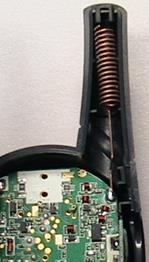
11 Example: Antenna Factor An electric field of 60.0 dbmv/m is incident on an antenna, as depicted. The electric field oscillates along the antenna axis. The antenna factor for this antenna is db/m. Determine the power input to the spectrum analyzer, in decibels referenced to 1 milliwatt. AF E V AF E V db dbμv/m dbμv 1
12 Dr. Gregory J. Mazzaro Fall 017 ELEC 45 Interference Control in Electronics Lecture 7(b) Building-Block Antennas Chapter 9 THE CITADEL, THE MILITARY COLLEGE OF SOUTH CAROLINA 171 Moultrie Street, Charleston, SC 9409
13 Hertzian ( Short ) Dipole Hertzian (or short ) dipole -- a straight-line antenna -- the length of the antenna (l) is much smaller than the wavelength of the radiation transmitted/received (l) I l l Aligned with the z axis, the E-field pattern is cylindrically symmetric (i.e. it does not vary with f ) and is given by and it follows that the average power density is E short dipole jkr I l e j sin ˆ θ l R I l 1 sin 8 l R avg normalized short F sin dipole 15
")
14 Half-Wave Dipole Antenna half-wave dipole -- a straight-line antenna -- the length of the antenna (l) is equal (or very close) to one-half of the radiated wavelength (l) The E-field pattern is derived by integrating the short dipole from l = l/4 to l = +l/4 and the result is cos cos jkr l I e E ˆ dipole j θ sin R I I avg cos cos F l dipole sin I cos cos 8 r sin normalized x f z F(, f) y 16

15 Quarter-Wave Monopole Antenna quarter-wave monopole -- a straight-line antenna near a ground plane -- l = l/4 z 0 z 0 I I I The E-field pattern is found from image theory: it is the same E the half-wave dipole, but only above the ground plane. E l 4 mono cos cos jkr I e j ˆ θ z 0 sin R 0 z 0 cos cos 4 F l mono sin 17
16 Table of Antenna arameters E transmitted (, f) R rad ( = 0 ) G max short dipole, length = l jkr I l e j sin ˆ θ l R l 80 l 1.50 half-wave dipole, l = l/ cos cos jkr I e j ˆ θ sin R 73 W 1.64 quarter-wave monopole, l = l/4 cos cos jkr I e j ˆ θ, z 0 sin R 36.5 W 3.8 small loop, area = S jkr S e I sin ˆ f l R 30 S 4 l dipole, arbitrary length l l l jkr I e cos l cos cos l j ˆ θ R sin 18
17 Example: Antenna, ower Density A 1-m-long dipole is excited by a 5-MHz current with an amplitude of 5 A. Determine the maximum radiated power density at a distance of km. u p c f l r avg 1 ReE H E kˆ avg S avg ds E short dipole jkr I l e j sin ˆ θ l R jkr cos cos I e l ˆ dipole j E θ R sin E arbitrary dipole 19 l l jkr I e cos l cos cos l j R sin θˆ
18 Dr. Gregory J. Mazzaro Fall 017 ELEC 45 Interference Control in Electronics Lecture 7(c) Antenna Gain and the Friis Equation Chapter 9 THE CITADEL, THE MILITARY COLLEGE OF SOUTH CAROLINA 171 Moultrie Street, Charleston, SC 9409
19 Antenna Gain antenna (power) gain: G or G p ( unitless, or in dbi ) -- a measure of the concentration of radiated power in a given direction -- very closely related to radiation intensity (F) -- includes radiation efficiency (loss in the antenna) Gp, f 4 R avg f, t directive gain: G d ( unitless, or in dbi ) -- nearly the same as power gain -- referenced to radiated power ( rad ) instead of power fed to the antenna ( t ) -- does not include radiation efficiency (loss) Gd, f 4 R avg f, rad t rad x R G R R G rad rad x t rad loss G d p d G p
20 Radiation Intensity vs. Gain normalized radiation intensity: F f, avg f, max f, avg antenna (power) gain: Gp, f 4 R avg f, t -- indicates the direction(s) in which the antenna radiates -- maximum value = 1 (or 0 db) -- commonly used to calculate relative levels of power received/transmitted -- in practice, typically plotted as a function of angle -- indicates the direction(s) in which the antenna radiates -- may increase indefinitely (in theory) -- commonly used to calculate absolute levels of power received/transmitted -- in practice, typically plotted as a function of frequency 3


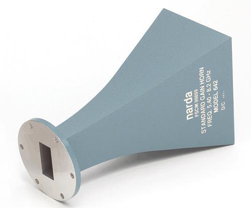
21 Radiation Intensity vs. Gain normalized radiation intensity: F f, avg f, max f, avg antenna (power) gain: Gp, f 4 R avg f, t ETS Lindgren horn antenna 4
22 The Friis Equation Friis Equation -- a power-budget equation, used to calculate power received/transmitted or the antenna properties necessary to establish/maintain communication -- generally written in two forms: efficiency & effective apertures OR antenna gains Derivation G t 4 R t A x eff rec rec r r t Transmitter (Tx) eff A t eff A r rec 1 G A x 4 R eff rec t r r t xt Receiver (Rx) xr substitute G t G r G G x G t t d,t x G r r d,r A eff l G d 4 eff eff xx t r At Ar l rec t t r t G G l R 4R 5
23 Example: Friis Equation Two antennas are separated by a distance of 00 l. The transmit antenna has a gain of 5 db and the receive antenna has a gain of 18 db. If 5 mw of power must be received, calculate the minimum required transmit power. 6 eff eff xx t r At Ar l rec t t r t G G l R 4R
Antenna Fundamentals Basics antenna theory and concepts
 Antenna Fundamentals Basics antenna theory and concepts M. Haridim Brno University of Technology, Brno February 2017 1 Topics What is antenna Antenna types Antenna parameters: radiation pattern, directivity,
Dr. John S. Seybold. November 9, IEEE Melbourne COM/SP AP/MTT Chapters
 Antennas Dr. John S. Seybold November 9, 004 IEEE Melbourne COM/SP AP/MTT Chapters Introduction The antenna is the air interface of a communication system An antenna is an electrical conductor or system
ELEC 425 Interference Control in Electronics Lecture 0 Introduction to the Course & Syllabus
 Dr. Gregory J. Mazzaro Fall 2017 ELEC 425 Interference Control in Electronics Lecture 0 Introduction to the Course & Syllabus THE CITADEL, THE MILITARY COLLEGE OF SOUTH CAROLINA 171 Moultrie Street, Charleston,
Antenna Parameters. Ranga Rodrigo. University of Moratuwa. December 15, 2008
 Antenna Parameters Ranga Rodrigo University of Moratuwa December 15, 2008 Ranga Rodrigo (University of Moratuwa) Antenna Parameters December 15, 2008 1 / 47 Summary of Last Week s Lecture 90 o Radiation
Fundamentals of Antennas. Prof. Ely Levine
 Fundamentals of Antennas Prof. Ely Levine levineel@zahav.net.il 1 Chapter 3 Wire Antennas 2 Types of Antennas 3 Isotropic Antenna Isotropic radiator is the simplest antenna mathematically Radiates all
ELEC 425 Interference Control in Electronics Lecture 6(a) Conducted Emissions & Susceptibility
 Conducted Emissions & Susceptibility") Dr. Gregory J. Mazzaro Fall 2017 ELEC 425 Interference Control in Electronics Lecture 6(a) Conducted Emissions & Susceptibility THE CITADEL, THE MILITARY COLLEGE OF SOUTH CAROLINA 171 Moultrie Street,
Dr. Gregory J. Mazzaro Fall 2017 ELEC 425 Interference Control in Electronics Lecture 6(a) Conducted Emissions & Susceptibility THE CITADEL, THE MILITARY COLLEGE OF SOUTH CAROLINA 171 Moultrie Street,
An Introduction to Antennas
 May 11, 010 An Introduction to Antennas 1 Outline Antenna definition Main parameters of an antenna Types of antennas Antenna radiation (oynting vector) Radiation pattern Far-field distance, directivity,
Half-Wave Dipole. Radiation Resistance. Antenna Efficiency
 Antennas Simple Antennas Isotropic radiator is the simplest antenna mathematically Radiates all the power supplied to it, equally in all directions Theoretical only, can t be built Useful as a reference:
EMG4066:Antennas and Propagation Exp 1:ANTENNAS MMU:FOE. To study the radiation pattern characteristics of various types of antennas.
 OBJECTIVES To study the radiation pattern characteristics of various types of antennas. APPARATUS Microwave Source Rotating Antenna Platform Measurement Interface Transmitting Horn Antenna Dipole and Yagi
Friis Formula and Effects
 Friis Formula and Effects Page 1 Friis transmission formula in free space is This equation assumes the following: Friis Formula and Effects G rg t λ (4πR). (1) 1. That the antennas are pointed at each
( ) 2 ( ) 3 ( ) + 1. cos! t " R / v p 1 ) H =! ˆ" I #l ' $ 2 ' 2 (18.20) * + ! ˆ& "I #l ' $ 2 ' , ( βr << 1. "l ' E! ˆR I 0"l ' cos& + ˆ& 0
 2 ( ) 3 ( ) + 1. cos! t R / v p 1 ) H =! ˆ I #l ' $ 2 ' 2 (18.20) * + ! ˆ& I #l ' $ 2 ' , ( βr << 1. l ' E! ˆR I 0l ' cos& + ˆ& 0") Summary Chapter 8. This last chapter treats the problem of antennas and radiation from antennas. We start with the elemental electric dipole and introduce the idea of retardation of potentials and fields
Summary Chapter 8. This last chapter treats the problem of antennas and radiation from antennas. We start with the elemental electric dipole and introduce the idea of retardation of potentials and fields
Propagation mechanisms
 RADIO SYSTEMS ETIN15 Lecture no: 2 Propagation mechanisms Ove Edfors, Department of Electrical and Information Technology Ove.Edfors@eit.lth.se Contents Short on db calculations Basics about antennas Propagation
KULLIYYAH OF ENGINEERING
 KULLIYYAH OF ENGINEERING DEPARTMENT OF ELECTRICAL & COMPUTER ENGINEERING ANTENNA AND WAVE PROPAGATION LABORATORY (ECE 4103) EXPERIMENT NO 3 RADIATION PATTERN AND GAIN CHARACTERISTICS OF THE DISH (PARABOLIC)
Antennas 1. Antennas
 Antennas Antennas 1! Grading policy. " Weekly Homework 40%. " Midterm Exam 30%. " Project 30%.! Office hour: 3:10 ~ 4:00 pm, Monday.! Textbook: Warren L. Stutzman and Gary A. Thiele, Antenna Theory and
The concept of transmission loss for radio links
 Recommendation ITU-R P.341-6 (09/2016) The concept of transmission loss for radio links P Series Radiowave propagation ii Rec. ITU-R P.341-6 Foreword The role of the Radiocommunication Sector is to ensure
Antenna Theory. Introduction
 1 Introduction Antenna Theory Antennas are device that designed to radiate electromagnetic energy efficiently in a prescribed manner. It is the current distributions on the antennas that produce the radiation.
EC ANTENNA AND WAVE PROPAGATION
 EC6602 - ANTENNA AND WAVE PROPAGATION FUNDAMENTALS PART-B QUESTION BANK UNIT 1 1. Define the following parameters w.r.t antenna: i. Radiation resistance. ii. Beam area. iii. Radiation intensity. iv. Directivity.
UNIT Write short notes on travelling wave antenna? Ans: Travelling Wave Antenna
 UNIT 4 1. Write short notes on travelling wave antenna? Travelling Wave Antenna Travelling wave or non-resonant or aperiodic antennas are those antennas in which there is no reflected wave i.e., standing
Annex 5. Determination of the interference field strength in the Land Mobile Service
 Annex 5 Determination of the interference field strength in the Land Mobile Service Annex 5, page 2 of 18 1 General 1.1 This calculation method is based on Recommendation ITU-R P.1546, taking into account
Range Considerations for RF Networks
 TI Technology Days 2010 Range Considerations for RF Networks Richard Wallace Abstract The antenna can be one of the most daunting components of wireless designs. Most information available relates to large
Antenna Engineering Lecture 3: Basic Antenna Parameters
 Antenna Engineering Lecture 3: Basic Antenna Parameters ELC 405a Fall 2011 Department of Electronics and Communications Engineering Faculty of Engineering Cairo University 2 Outline 1 Radiation Pattern
Notes 21 Introduction to Antennas
 ECE 3317 Applied Electromagnetic Waves Prof. David R. Jackson Fall 018 Notes 1 Introduction to Antennas 1 Introduction to Antennas Antennas An antenna is a device that is used to transmit and/or receive
ANTENNA THEORY. Analysis and Design. CONSTANTINE A. BALANIS Arizona State University. JOHN WILEY & SONS New York Chichester Brisbane Toronto Singapore
 ANTENNA THEORY Analysis and Design CONSTANTINE A. BALANIS Arizona State University JOHN WILEY & SONS New York Chichester Brisbane Toronto Singapore Contents Preface xv Chapter 1 Antennas 1 1.1 Introduction
ANTENNA INTRODUCTION / BASICS
 ANTENNA INTRODUCTION / BASICS RULES OF THUMB: 1. The Gain of an antenna with losses is given by: 2. Gain of rectangular X-Band Aperture G = 1.4 LW L = length of aperture in cm Where: W = width of aperture
Antenna & Propagation. Antenna Parameters
 For updated version, please click on http://ocw.ump.edu.my Antenna & Propagation Antenna Parameters by Nor Hadzfizah Binti Mohd Radi Faculty of Electric & Electronics Engineering hadzfizah@ump.edu.my Chapter
ANTENNA INTRODUCTION / BASICS
 Rules of Thumb: 1. The Gain of an antenna with losses is given by: G 0A 8 Where 0 ' Efficiency A ' Physical aperture area 8 ' wavelength ANTENNA INTRODUCTION / BASICS another is:. Gain of rectangular X-Band
25. Antennas II. Radiation patterns. Beyond the Hertzian dipole - superposition. Directivity and antenna gain. More complicated antennas
 25. Antennas II Radiation patterns Beyond the Hertzian dipole - superposition Directivity and antenna gain More complicated antennas Impedance matching Reminder: Hertzian dipole The Hertzian dipole is
Final Examination. 22 April 2013, 9:30 12:00. Examiner: Prof. Sean V. Hum. All non-programmable electronic calculators are allowed.
 UNIVERSITY OF TORONTO FACULTY OF APPLIED SCIENCE AND ENGINEERING The Edward S. Rogers Sr. Department of Electrical and Computer Engineering ECE 422H1S RADIO AND MICROWAVE WIRELESS SYSTEMS Final Examination
Traveling Wave Antennas
 Traveling Wave Antennas Antennas with open-ended wires where the current must go to zero (dipoles, monopoles, etc.) can be characterized as standing wave antennas or resonant antennas. The current on these
EEM.Ant. Antennas and Propagation
 EEM.ant/0304/08pg/Req: None 1/8 UNIVERSITY OF SURREY Department of Electronic Engineering MSc EXAMINATION EEM.Ant Antennas and Propagation Duration: 2 Hours Spring 2003/04 READ THESE INSTRUCTIONS Answer
ELEG 648 Radiation/Antennas I. Mark Mirotznik, Ph.D. Associate Professor The University of Delaware
 ELEG 648 Radiation/Antennas I Mark Mirotznik Ph.D. Associate Professor The University of Delaware A jk rr ' e ' r J r dv ' 4 r r ' F If we have magnetic sources jk rr ' e ' r M r dv ' 4 r r ' Field
Linear Wire Antennas. EE-4382/ Antenna Engineering
 Linear Wire Antennas EE-438/5306 - Antenna Engineering Outline Introduction Infinitesimal Dipole Small Dipole Finite Length Dipole Half-Wave Dipole Ground Effect Constantine A. Balanis, Antenna Theory:
6 Radio and RF. 6.1 Introduction. Wavelength (m) Frequency (Hz) Unit 6: RF and Antennas 1. Radio waves. X-rays. Microwaves. Light
 Frequency (Hz) Unit 6: RF and Antennas 1. Radio waves. X-rays. Microwaves. Light") 6 Radio and RF Ref: http://www.asecuritysite.com/wireless/wireless06 6.1 Introduction The electromagnetic (EM) spectrum contains a wide range of electromagnetic waves, from radio waves up to X-rays (as
6 Radio and RF Ref: http://www.asecuritysite.com/wireless/wireless06 6.1 Introduction The electromagnetic (EM) spectrum contains a wide range of electromagnetic waves, from radio waves up to X-rays (as
UNIT Explain the radiation from two-wire. Ans: Radiation from Two wire
 UNIT 1 1. Explain the radiation from two-wire. Radiation from Two wire Figure1.1.1 shows a voltage source connected two-wire transmission line which is further connected to an antenna. An electric field
Impedance and Loop Antennas
 Impedance and Loop Antennas Ranga Rodrigo University of Moratuwa January 4, 2009 Ranga Rodrigo (University of Moratuwa) Impedance and Loop Antennas January 4, 2009 1 / 41 Gain Summary of Last Week s Lecture
UNIVERSITI MALAYSIA PERLIS
 UNIVERSITI MALAYSIA PERLIS SCHOOL OF COMPUTER & COMMUNICATIONS ENGINEERING EKT 341 LABORATORY MODULE LAB 2 Antenna Characteristic 1 Measurement of Radiation Pattern, Gain, VSWR, input impedance and reflection
CHAPTER 5 THEORY AND TYPES OF ANTENNAS. 5.1 Introduction
 CHAPTER 5 THEORY AND TYPES OF ANTENNAS 5.1 Introduction Antenna is an integral part of wireless communication systems, considered as an interface between transmission line and free space [16]. Antenna
ELEC4604. RF Electronics. Experiment 1
 ELEC464 RF Electronics Experiment ANTENNA RADATO N PATTERNS. ntroduction The performance of RF communication systems depend critically on the radiation characteristics of the antennae it employs. These
CHAPTER 8 ANTENNAS 1
 CHAPTER 8 ANTENNAS 1 2 Antennas A good antenna works A bad antenna is a waste of time & money Antenna systems can be very inexpensive and simple They can also be very expensive 3 Antenna Considerations
Introduction Antenna Ranges Radiation Patterns Gain Measurements Directivity Measurements Impedance Measurements Polarization Measurements Scale
 Chapter 17 : Antenna Measurement Introduction Antenna Ranges Radiation Patterns Gain Measurements Directivity Measurements Impedance Measurements Polarization Measurements Scale Model Measurements 1 Introduction
Antenna Theory EELE 5445
 Antenna Theory EELE 5445 Lecture 6: Dipole Antenna Dr. Mohamed Ouda Electrical Engineering Department Islamic University of Gaza 2013 The dipole and the monopole The dipole and the monopole are arguably
Practical Antennas and. Tuesday, March 4, 14
 Practical Antennas and Transmission Lines Goals Antennas are the interface between guided waves (from a cable) and unguided waves (in space). To understand the various properties of antennas, so as to
Field Intensity Units
 Page 1 of 5 Field Intensity Units Q: What is the difference between dbu, dbm, dbuv, and other units? A: There is a great deal of confusion when engineers, technicians, and equipment salespersons talk about
What does reciprocity mean
 Antennas Definition of antenna: A device for converting electromagnetic radiation in space into electrical currents in conductors or vice-versa. Radio telescopes are antennas Reciprocity says we can treat
Part 1: Standing Waves - Measuring Wavelengths
 Experiment 7 The Microwave experiment Aim: This experiment uses microwaves in order to demonstrate the formation of standing waves, verifying the wavelength λ of the microwaves as well as diffraction from
The Benefits of BEC s Antenna Design
 The Benefits of BEC s Antenna Design Overview The explosive growth of wireless data communications is fast emerging with high peak data rates, which require superior antenna performance and design to support
I J E E Volume 5 Number 1 January-June 2013 pp
 I J E E Volume 5 Number 1 January-June 2013 pp. 21-25 Serials Publications, ISSN : 0973-7383 Various Antennas and Its Applications in Wireless Domain: A Review Paper P.A. Ambresh 1, P.M. Hadalgi 2 and
HHTEHHH THEORY ANALYSIS AND DESIGN. CONSTANTINE A. BALANIS Arizona State University
 HHTEHHH THEORY ANALYSIS AND DESIGN CONSTANTINE A. BALANIS Arizona State University JOHN WILEY & SONS, INC. New York Chichester Brisbane Toronto Singapore Contents Preface V CHAPTER 1 ANTENNAS 1.1 Introduction
ELEC Course Objectives/Proficiencies
 Lecture 1 -- to identify (and list examples of) intentional and unintentional receivers -- to list three (broad) ways of reducing/eliminating interference -- to explain the differences between conducted/radiated
"Natural" Antennas. Mr. Robert Marcus, PE, NCE Dr. Bruce C. Gabrielson, NCE. Security Engineering Services, Inc. PO Box 550 Chesapeake Beach, MD 20732
 Published and presented: AFCEA TEMPEST Training Course, Burke, VA, 1992 Introduction "Natural" Antennas Mr. Robert Marcus, PE, NCE Dr. Bruce C. Gabrielson, NCE Security Engineering Services, Inc. PO Box
You will need the following pieces of equipment to complete this experiment: Wilkinson power divider (3-port board with oval-shaped trace on it)
") UNIVERSITY OF TORONTO FACULTY OF APPLIED SCIENCE AND ENGINEERING The Edward S. Rogers Sr. Department of Electrical and Computer Engineering ECE422H1S: RADIO AND MICROWAVE WIRELESS SYSTEMS EXPERIMENT 1:
UNIVERSITY OF TORONTO FACULTY OF APPLIED SCIENCE AND ENGINEERING The Edward S. Rogers Sr. Department of Electrical and Computer Engineering ECE422H1S: RADIO AND MICROWAVE WIRELESS SYSTEMS EXPERIMENT 1:
Introduction to Radar Systems. Radar Antennas. MIT Lincoln Laboratory. Radar Antennas - 1 PRH 6/18/02
 Introduction to Radar Systems Radar Antennas Radar Antennas - 1 Disclaimer of Endorsement and Liability The video courseware and accompanying viewgraphs presented on this server were prepared as an account
ECE 4370: Antenna Engineering TEST 1 (Fall 2017)
") Name: GTID: ECE 437: Antenna Engineering TEST 1 Fall 17) Please read all instructions before continuing with the test. This is a closed notes, closed book, closed friend, open mind test. On your desk you
Name: GTID: ECE 437: Antenna Engineering TEST 1 Fall 17) Please read all instructions before continuing with the test. This is a closed notes, closed book, closed friend, open mind test. On your desk you
RADAR Antennas R A D A R R A D A R S Y S T E M S S Y S T E M S. Lecture DR Sanjeev Kumar Mishra. 2 max
 Y T E M Y T E M anjeev Kumar Mishra Lecture 17-20 ntennas i p r t t ne L L L N kt BF PG 1 0 3 2 max 4 ) / ( 4 2 Y T E M ntenna: n antenna is an electromagnetic radiator, a sensor, a transducer and an impedance
Fourth Year Antenna Lab
 Fourth Year Antenna Lab Name : Student ID#: Contents 1 Wire Antennas 1 1.1 Objectives................................................. 1 1.2 Equipments................................................ 1
24. Antennas. What is an antenna. Types of antennas. Reciprocity
 4. Antennas What is an antenna Types of antennas Reciprocity Hertzian dipole near field far field: radiation zone radiation resistance radiation efficiency Antennas convert currents to waves An antenna
Link Budget Calculation
 Link Budget Calculation Training materials for wireless trainers This 60 minute talk is about estimating wireless link performance by using link budget calculations. It also introduces the Radio Mobile
Antenna Trainer EAN. Technical Teaching Equipment INTRODUCTION
 Antenna Trainer EAN Technical Teaching Equipment Products Products range Units 3.-Communications INTRODUCTION Antennas are the main element of aerial communications. They are the transition between a transmission
Rec. ITU-R F RECOMMENDATION ITU-R F *
 Rec. ITU-R F.162-3 1 RECOMMENDATION ITU-R F.162-3 * Rec. ITU-R F.162-3 USE OF DIRECTIONAL TRANSMITTING ANTENNAS IN THE FIXED SERVICE OPERATING IN BANDS BELOW ABOUT 30 MHz (Question 150/9) (1953-1956-1966-1970-1992)
Continuous Arrays Page 1. Continuous Arrays. 1 One-dimensional Continuous Arrays. Figure 1: Continuous array N 1 AF = I m e jkz cos θ (1) m=0
 m=0") Continuous Arrays Page 1 Continuous Arrays 1 One-dimensional Continuous Arrays Consider the 2-element array we studied earlier where each element is driven by the same signal (a uniform excited array),
Continuous Arrays Page 1 Continuous Arrays 1 One-dimensional Continuous Arrays Consider the 2-element array we studied earlier where each element is driven by the same signal (a uniform excited array),
Antenna Glossary. BEAMWIDTH The angle of signal coverage provided by an antenna. Beamwidth usually decreases as antenna gain increases.
 ADAPTIVE (SMART) ANTENNA An antenna system having circuit elements associated with its radiating elements such that one or more of the antenna properties are controlled by the received signal. ANTENNA
BHARATHIDASAN ENGINEERING COLLEGE NATTARAMPALLI Frequently Asked Questions (FAQ) Unit 1
 Unit 1") BHARATHIDASAN ENGINEERING COLLEGE NATTARAMPALLI 635854 Frequently Asked Questions (FAQ) Unit 1 Degree / Branch : B.E / ECE Sem / Year : 3 rd / 6 th Sub Name : Antennas & Wave Propagation Sub Code : EC6602
BHARATHIDASAN ENGINEERING COLLEGE NATTARAMPALLI 635854 Frequently Asked Questions (FAQ) Unit 1 Degree / Branch : B.E / ECE Sem / Year : 3 rd / 6 th Sub Name : Antennas & Wave Propagation Sub Code : EC6602
Antenna and Noise Concepts
 Antenna and Noise Concepts 1 Antenna concepts 2 Antenna impedance and efficiency 3 Antenna patterns 4 Receiving antenna performance Levis, Johnson, Teixeira (ESL/OSU) Radiowave Propagation August 17, 2018
Characteristics of HF Coastal Radars
 Function Characteristics System 1 Maximum operational (measurement) range** Characteristics of HF Coastal Radars 5 MHz Long-range oceanographic 160-220 km average during (daytime)* System 2 System 3 System
Electronically Steerable planer Phased Array Antenna
 Electronically Steerable planer Phased Array Antenna Amandeep Kaur Department of Electronics and Communication Technology, Guru Nanak Dev University, Amritsar, India Abstract- A planar phased-array antenna
KINGS COLLEGE OF ENGINEERING. DEPARTMENT OF ELECTRONICS AND COMMUNICATION ENGINEERING Academic Year (Even Sem) QUESTION BANK (AUTT-R2008)
 QUESTION BANK (AUTT-R2008)") KINGS COLLEGE OF ENGINEERING DEPARTMENT OF ELECTRONICS AND COMMUNICATION ENGINEERING Academic Year 2012-2013(Even Sem) QUESTION BANK (AUTT-R2008) SUBJECT CODE /NAME: EC 1352 / ANTENNEA AND WAVE PROPAGATION
KINGS COLLEGE OF ENGINEERING DEPARTMENT OF ELECTRONICS AND COMMUNICATION ENGINEERING Academic Year 2012-2013(Even Sem) QUESTION BANK (AUTT-R2008) SUBJECT CODE /NAME: EC 1352 / ANTENNEA AND WAVE PROPAGATION
ANTENNAS AND WAVE PROPAGATION EC602
 ANTENNAS AND WAVE PROPAGATION EC602 B.Tech Electronics & Communication Engineering, Semester VI INSTITUTE OF TECHNOLOGY NIRMA UNIVERSITY 1 Lesson Planning (L-3,P-2,C-4) Chapter No. Name Hours 1. Basic
Antenna Fundamentals. Microwave Engineering EE 172. Dr. Ray Kwok
 Antenna Fundamentals Microwave Engineering EE 172 Dr. Ray Kwok Reference Antenna Theory and Design Warran Stutzman, Gary Thiele, Wiley & Sons (1981) Microstrip Antennas Bahl & Bhartia, Artech House (1980)
Travelling Wave, Broadband, and Frequency Independent Antennas. EE-4382/ Antenna Engineering
 Travelling Wave, Broadband, and Frequency Independent Antennas EE-4382/5306 - Antenna Engineering Outline Traveling Wave Antennas Introduction Traveling Wave Antennas: Long Wire, V Antenna, Rhombic Antenna
Differential and Single Ended Elliptical Antennas for GHz Ultra Wideband Communication
 Differential and Single Ended Elliptical Antennas for 3.1-1.6 GHz Ultra Wideband Communication Johnna Powell Anantha Chandrakasan Massachusetts Institute of Technology Microsystems Technology Laboratory
Radiation and Antennas
 Chapter 9 Radiation and Antennas. Basic Formulations 2. Hertzian Dipole Antenna 3. Linear Antennas An antenna is a device to transmit or receive electromagnetic power more efficiently with a more directive
KINGS COLLEGE OF ENGINEERING DEPARTMENT OF ELECTRONICS AND COMMUNICATION ENGINEERING QUESTION BANK
 KINGS COLLEGE OF ENGINEERING DEPARTMENT OF ELECTRONICS AND COMMUNICATION ENGINEERING QUESTION BANK SUB.NAME : ANTENNAS & WAVE PROPAGATION SUB CODE : EC 1352 YEAR : III SEMESTER : VI UNIT I: ANTENNA FUNDAMENTALS
ANTENNA THEORY ANALYSIS AND DESIGN
 ANTENNA THEORY ANALYSIS AND DESIGN THIRD EDITION Constantine A. Balanis WILEY- INTERSCIENCE A JOHN WILEY & SONS. INC.. PUBLICATION ial iel pi ial ial ial IBl ial ial ial pi Sl Contents Preface Xlll 1 Antennas
Fields and Waves I. Lecture 26. Intro to Antennas & Propagation K. A. Connor
 Fields and Waves I Lecture 26 Intro to Antennas & Propagation K. A. Connor Electrical, Computer, and Systems Engineering Department Rensselaer Polytechnic Institute, Troy, NY These Slides Were Prepared
THE ELECTROMAGNETIC FIELD THEORY. Dr. A. Bhattacharya
 1 THE ELECTROMAGNETIC FIELD THEORY Dr. A. Bhattacharya The Underlying EM Fields The development of radar as an imaging modality has been based on power and power density It is important to understand some
Chapter 4 The RF Link
 Chapter 4 The RF Link The fundamental elements of the communications satellite Radio Frequency (RF) or free space link are introduced. Basic transmission parameters, such as Antenna gain, Beamwidth, Free-space
Newsletter 2.0. Antenna Magus version 2.0 released! New Array synthesis tool. April 2010
 Newsletter 2.0 April 2010 Antenna Magus version 2.0 released! We are very proud to announce the second major release of Antenna Magus, Version 2.0. Looking back over the past 11 months since release 1.0
Propagation curves and conditions of validity (homogeneous paths)
") Rec. ITU-R P.368-7 1 RECOMMENDATION ITU-R P.368-7 * GROUND-WAVE PROPAGATION CURVES FOR FREQUENCIES BETWEEN 10 khz AND 30 MHz (1951-1959-1963-1970-1974-1978-1982-1986-1990-1992) Rec. 368-7 The ITU Radiocommunication
Rec. ITU-R P.368-7 1 RECOMMENDATION ITU-R P.368-7 * GROUND-WAVE PROPAGATION CURVES FOR FREQUENCIES BETWEEN 10 khz AND 30 MHz (1951-1959-1963-1970-1974-1978-1982-1986-1990-1992) Rec. 368-7 The ITU Radiocommunication
RECOMMENDATION ITU-R F *
 Rec. ITU-R F.699-6 1 RECOMMENATION ITU-R F.699-6 * Reference radiation patterns for fixed wireless system antennas for use in coordination studies and interference assessment in the frequency range from
RECOMMENDATION ITU-R BS.80-3 * Transmitting antennas in HF broadcasting
 Rec. ITU-R BS.80-3 1 RECOMMENDATION ITU-R BS.80-3 * Transmitting antennas in HF broadcasting (1951-1978-1986-1990) The ITU Radiocommunication Assembly, considering a) that a directional transmitting antenna
Antennas & wave Propagation ASSIGNMENT-I
 Shri Vishnu Engineering College for Women :: Bhimavaram Department of Electronics & Communication Engineering Antennas & wave Propagation 1. Define the terms: i. Antenna Aperture ii. Beam Width iii. Aperture
ECEn 665: Antennas and Propagation for Wireless Communications 48. Since the integrand is periodic, we can change the integration limits to
 ECEn 665: Antennas and Propagation for Wireless Communications 48 3.3 Loop Antenna An electric dipole antenna radiates an electric field that is aligned with the dipole and a magnetic field that radiates
Antennas 101 Don t Be a 0.97 db Weakling! Ward Silver NØAX
 Antennas 101 Don t Be a 0.97 db Weakling! Ward Silver NØAX Overview Antennas 101 2 Overview Basic Antennas: Ground Plane / Dipole How Gain and Nulls are Formed How Phased Arrays Work How Yagis Work (simplified)
Theory of Helix Antenna
 Theory of Helix Antenna Tariq Rahim School of Electronic and information, NWPU, Xian china Review on Helix Antenna 1 Introduction The helical antenna is a hybrid of two simple radiating elements, the dipole
Multi-Path Fading Channel
 Instructor: Prof. Dr. Noor M. Khan Department of Electronic Engineering, Muhammad Ali Jinnah University, Islamabad Campus, Islamabad, PAKISTAN Ph: +9 (51) 111-878787, Ext. 19 (Office), 186 (Lab) Fax: +9
CHAPTER 5 PRINTED FLARED DIPOLE ANTENNA
 CHAPTER 5 PRINTED FLARED DIPOLE ANTENNA 5.1 INTRODUCTION This chapter deals with the design of L-band printed dipole antenna (operating frequency of 1060 MHz). A study is carried out to obtain 40 % impedance
Radiation characteristics of a dipole antenna in free space
 Department of Electrical and Electronic Engineering (EEE), Bangladesh University of Engineering and Technology (BUET). EEE 434: Microwave Engineering Laboratory Experiment No.: A1 Radiation characteristics
4/29/2012. General Class Element 3 Course Presentation. Ant Antennas as. Subelement G9. 4 Exam Questions, 4 Groups
 General Class Element 3 Course Presentation ti ELEMENT 3 SUB ELEMENTS General Licensing Class Subelement G9 Antennas and Feedlines 4 Exam Questions, 4 Groups G1 Commission s Rules G2 Operating Procedures
Millimetre-wave Phased Array Antennas for Mobile Terminals
 Millimetre-wave Phased Array Antennas for Mobile Terminals Master s Thesis Alberto Hernández Escobar Aalborg University Department of Electronic Systems Fredrik Bajers Vej 7B DK-9220 Aalborg Contents
The Radio Channel. COS 463: Wireless Networks Lecture 14 Kyle Jamieson. [Parts adapted from I. Darwazeh, A. Goldsmith, T. Rappaport, P.
 The Radio Channel COS 463: Wireless Networks Lecture 14 Kyle Jamieson [Parts adapted from I. Darwazeh, A. Goldsmith, T. Rappaport, P. Steenkiste] Motivation The radio channel is what limits most radio
Groundwave Propagation, Part One
 Groundwave Propagation, Part One 1 Planar Earth groundwave 2 Planar Earth groundwave example 3 Planar Earth elevated antenna effects Levis, Johnson, Teixeira (ESL/OSU) Radiowave Propagation August 17,
Antenna Fundamentals
 HTEL 104 Antenna Fundamentals The antenna is the essential link between free space and the transmitter or receiver. As such, it plays an essential part in determining the characteristics of the complete
Chapter 7 Design of the UWB Fractal Antenna
 Chapter 7 Design of the UWB Fractal Antenna 7.1 Introduction F ractal antennas are recognized as a good option to obtain miniaturization and multiband characteristics. These characteristics are achieved
5.9 GHz V2X Modem Performance Challenges with Vehicle Integration
 5.9 GHz V2X Modem Performance Challenges with Vehicle Integration October 15th, 2014 Background V2V DSRC Why do the research? Based on 802.11p MAC PHY ad-hoc network topology at 5.9 GHz. Effective Isotropic
FIELD INTENSITY AND SIGNAL LEVEL
 FIELD INTENSITY AND SIGNAL LEVEL It is important to understand the relationship between field intensity and the signal level at the input to a receiver or other monitoring device. For example, pager sensitivity
4.4. Experimental Results and Analysis
 4.4. Experimental Results and Analysis 4.4.1 Measurement of the IFA Against a Large Ground Plane The Inverted-F Antenna (IFA) discussed in Section 4.3.1 was modeled over an infinite ground plane using
Mobile Communications
 Mobile Communications Part IV- Propagation Characteristics Professor Z Ghassemlooy School of Computing, Engineering and Information Sciences University of Northumbria U.K. http://soe.unn.ac.uk/ocr Contents
Antennas and Propagation Chapters T4, G7, G8 Antenna Fundamentals, More Antenna Types, Feed lines and Measurements, Propagation
 Antennas and Propagation Chapters T4, G7, G8 Antenna Fundamentals, More Antenna Types, Feed lines and Measurements, Propagation =============================================================== Antenna Fundamentals
RADIATION PATTERNS. The half-power (-3 db) beamwidth is a measure of the directivity of the antenna.
 beamwidth is a measure of the directivity of the antenna.") RADIATION PATTERNS The radiation pattern is a graphical depiction of the relative field strength transmitted from or received by the antenna. Antenna radiation patterns are taken at one frequency, one
RADIATION PATTERNS The radiation pattern is a graphical depiction of the relative field strength transmitted from or received by the antenna. Antenna radiation patterns are taken at one frequency, one
REFERENCE GUIDE External Antennas Guide 1
 REFERENCE GUIDE External s Guide 1 Xirrus External s Guide Overview To optimize the overall performance of a Xirrus WLAN in an outdoor deployment it is important to understand how to maximize coverage