ANTENNA INTRODUCTION / BASICS
|
|
|
- Bertha Stafford
- 5 years ago
- Views:
Transcription


1 ANTENNA INTRODUCTION / BASICS RULES OF THUMB: 1. The Gain of an antenna with losses is given by: 2. Gain of rectangular X-Band Aperture G = 1.4 LW L = length of aperture in cm Where: W = width of aperture in cm 3. Gain of Circular X-Band Aperture 4. Gain of an isotropic antenna radiating in a uniform spherical pattern is one (0 db). 5. Antenna with a 20 degree beamwidth has a 20 db gain db beamwidth is approximately equal to the angle from the peak of the power to the first null (see figure at right). 7. Parabolic Antenna Beamwidth:


2 ANTENNA BASICS The antenna equations which follow relate to Figure 1 as a typical antenna. In Figure 1, BW is the azimuth beamwidth and BW is the elevation beamwidth. Beamwidth is normally measured at the half-power or -3 db point unless otherwise specified. See Glossary. The gain or directivity of an antenna is the ratio of the radiation intensity in a given direction to the radiation intensity averaged over all directions. Quite often directivity and gain are used interchangeably. The difference is that directivity neglects antenna losses such as dielectric, resistance, polarization, and VSWR losses. Since these losses in most classes of antennas are usually quite small, the directivity and gain will be approximately equal (disregarding unwanted pattern characteristics). Normalizing a radiation pattern by the integrated total power yields the directivity of the antenna. This concept in shown in equation form by: Another important concept is that when the angle in which the radiation is constrained is reduced, the directive gain goes up. For example, using an isotropic radiating source, the gain
), the power radiated, P in, would be the same but the area would be half as much, so the gain would double to 3 db.")
 at which measurements are taken. Real antennas are different, however, and do not have an ideal radiation distribution.")
3 would be 0 db by definition (Figure 2(a)) and the power density (P d ) at any given point would be the power in (P in ) divided by the surface area of the imaginary sphere at a distance R from the source. If the spacial angle was decreased to one hemisphere (Figure 2(b)), the power radiated, P in, would be the same but the area would be half as much, so the gain would double to 3 db. Likewise if the angle is a quarter sphere, (Figure 2(c)), the gain would be 6 db. Figure 2(d) shows a pencil beam. The gain is independent of actual power output and radius (distance) at which measurements are taken. Real antennas are different, however, and do not have an ideal radiation distribution. Energy varies with angular displacement and losses occur due to sidelobes. However, if we can measure the pattern, and determine the beamwidth we can use two (or more) ideal antenna models to approximate a real antenna pattern as shown in Figure 3.
 Approximating an antenna pattern using an elliptical area, and (2) Approximating an antenna pattern using a rectangular")
4 Assuming the antenna pattern is uniform, the gain is equal to the area of the isotropic sphere (4 r 2 ) divided by the sector (cross section) area. It can be shown that: From this point, two different models are presented: (1) Approximating an antenna pattern using an elliptical area, and (2) Approximating an antenna pattern using a rectangular area. Approximating the antenna pattern as an elliptical area: Area of ellipse = a b = [ (r sin )/2 ][ (r sin )/2 ]= ( r 2 sin sin )/4 For small angles, sin = in radians, so: The second term in the equation above is very close to equation [3].
 = 28888, or in log form: 10 log G = 44.")
5 For a very directional radar dish with a beamwidth of 1 and an average efficiency of 55%: Ideally: G = 52525, or in db form: 10 log G =10 log = 47.2 db With efficiency taken into account, G = 0.55(52525) = 28888, or in log form: 10 log G = 44.6 db Approximating the antenna pattern as a rectangular area: a = r sin, b = r sin, area = ab = r 2 sin sin For small angles, sin = in radians, so: The second term in the equation above is identical to equation [3]. Converting to db: For a very directional radar dish with a beamwidth of 1 and an average efficiency of 70%: Ideally (in db form): 10 log G =10 log = 46.2 db. With efficiency taken into account, G = 0.7(41253) = 28877, or in log form: 10 log G = 44.6 db Comparison between elliptical and rectangular areas for antenna pattern models
![By using the rectangular model there is a direct correlation between the development of gain in equation [5] and the ideal gain of equation [3].](/docs-images/85/92570687/images/6-1.jpg "The elliptical model has about one db difference from the ideal calculation, but will yield the same real antenna gain when appropriate efficiencies are assumed.")
.")
6 By using the rectangular model there is a direct correlation between the development of gain in equation [5] and the ideal gain of equation [3]. The elliptical model has about one db difference from the ideal calculation, but will yield the same real antenna gain when appropriate efficiencies are assumed. The upper plot of Figure 4 shows the gain for an ideal antenna pattern using the elliptical model. The middle plot shows the gain for an ideal antenna using the rectangular model. The lower plot of Figure 4 shows the gain of a typical real antenna (rectangular model using an efficiency of 70%or elliptical model using an efficiency of 47%). GAIN AS A FUNCTION OF When = 0, each wave source in Figure 5 is in phase with one another and a maximum is produced in that direction. Conversely, nulls to either side of the main lobe will occur when the waves radiating from the antenna cancel each other. The first null occurs when there is a phase difference of /2 in the wave fronts emanating from the aperture. To aid in
7 visualizing what happens, consider each point in the antenna aperture, from A to C in Figure 5, as a point source of a spherical wave front. If viewed from infinity, the electromagnetic waves from each point interfere with each other, and when, for a particular direction, in Figure 5, each wave source has a corresponding point that is one-half wavelength out of phase, a null is produced in that direction due to destructive interference. In Figure 5, the wave emanating from point A is out of phase with the wave from point B by one-half of a wavelength. Hence, they cancel. Similarly, a point just to the right of point A cancels with a point just to the right of point B, and so on across the entire aperture. Therefore, the first null in the radiation pattern is given by: Sin = /L and, in radians, = /L (for small angles) [7] As the angle off boresight is increased beyond the first null, the intensity of the radiation pattern rises then falls, until the second null is reached. This corresponds to a phase difference of two wavelengths between the left and right edges of the aperture. In this case, the argument proceeds as before, except now the aperture is divided into four segments (point A canceling with a point halfway between A and B, and so on). The angle is the angle from the center (maximum) of the radiation pattern to the first null. The null-to-null beam width is 2. Generally, we are interested in the half-power (3 db) beamwidth. It turns out that this beamwidth is approximately one-half of the null-to-null beamwidth, so that: BW 3 db is approximately (1/2)(2 ) = /L [8] Therefore, beamwidth is a function of the antenna dimension "L" and the wavelength of the signal. It can be expressed as follows: (Note: for circular antennas, L in the following equations = diameter) Bw (az) = /L Az eff and BW (el) = /L El eff [9] Substituting the two variations of equation [9] into equation [3] and since L Az eff times L El eff = A e (effective capture area of the antenna), we have: Note: This equation is approximate since aperture efficiency isn't included as is done later in equation [12]. The efficiency (discussed later) will reduce the gain by a factor of 30-50%, i.e. real gain =.5 to.7 times theoretical gain. Unity Gain Antenna.
8 If a square antenna is visualized and G=1, A e = 2 / 4. When a dimension is greater than 0.28 (approximately 1/4 ) it is known as an electrically large antenna, and the antenna will have a gain greater than one (positive gain when expressed in db). Conversely, when the dimension is less than 0.28 (Approximately 1/4 )(an electrically small antenna), the gain will be less than one (negative gain when expressed in db). Therefore, a unity gain antenna can be approximated by an aperture that is 1/4 by 1/4. Beamwidth as a Function of Aperture Length It can be seen from Figure 5, that the wider the antenna aperture (L), the narrower the beamwidth will be for the same. Therefore, if you have a rectangular shaped horn antenna, the radiation pattern from the wider side will be narrower than the radiation pattern from the narrow side. APERTURE EFFICIENCY, The Antenna Aperture Efficiency,, is a factor which includes all reductions from the maximum gain. can be expressed as a percentage, or in db. Several types of "loss" must be accounted for in the efficiency, : (1) Illumination efficiency which is the ratio of the directivity of the antenna to the directivity of a uniformly illuminated antenna of the same aperture size, (2) Phase error loss or loss due to the fact that the aperture is not a uniform phase surface, (3) Spillover loss (Reflector Antennas) which reflects the energy spilling beyond the edge of the reflector into the back lobes of the antenna, (4) Mismatch (VSWR) loss, derived from the reflection at the feed port due to impedance mismatch (especially important for low frequency antennas), and (5) RF losses between the antenna and the antenna feed port or measurement point. The aperture efficiency,, is also known as the illumination factor, and includes items (1) and (2) above; it does not result in any loss of power radiated but affects the gain and pattern. It is nominally for a planer array and 0.13 to 0.8 with a nominal value of 0.5 for a parabolic antenna, however can vary significantly. Other antennas include the spiral ( ), the horn ( ), the double ridge horn ( ), and the conical log spiral ( ). Items (3), (4), and (5) above represent RF or power losses which can be measured. The efficiency varies and generally gets lower with wider bandwidths. Also note that the gain equation is optimized for small angles - see derivation of wavelength portion of equation [7]. This explains why efficiency also gets lower for wider beamwidth antennas. EFFECTIVE CAPTURE AREA
9 Effective capture area (A e ) is the product of the physical aperture area (A) and the aperture efficiency ( ) or: GAIN AS A FUNCTION OF APERTURE EFFICIENCY The Gain of an antenna with losses is given by: Note that the gain is proportional to the aperture area normalized by the square of the wavelength. For example, if the frequency is doubled, (half the wavelength), the aperture could be decreased four times to maintain the same gain. BEAM FACTOR Antenna size and beamwidth are also related by the beam factor defined by: Beam Factor = (D/ )(Beamwidth) where D = antenna dimension in wavelengths. The beam factor is approximately invariant with antenna size, but does vary with type of antenna aperture illumination or taper. The beam factor typically varies from degrees. APERTURE ILLUMINATION (TAPER) The aperture illumination or illumination taper is the variation in amplitude across the aperture. This variation can have several effects on the antenna performance: (1) reduction in gain, (2) reduced (lower) sidelobes in most cases, and (3) increased antenna beamwidth and beam factor. Tapered illumination occurs naturally in reflector antennas due to the feed radiation pattern and the variation in distance from the feed to different portions of the reflector. Phase can also vary across the aperture which also affects the gain, efficiency, and beamwidth. CIRCULAR ANTENNA GAIN
![Solving equation [12] in db, for a circular antenna with area D 2 /4, we have: 10 Log G = 20 Log (D/ ) + 10 Log ( ) + 9.](/docs-images/85/92570687/images/10-1.jpg "94 db where D = diameter [13] This data is depicted in the nomograph of Figure 6. For example, a six foot diameter antenna operating at 9 GHz would have approximately 44.")
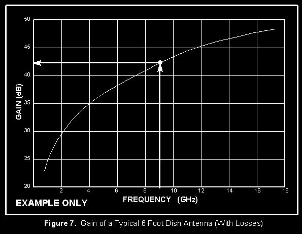
10 Solving equation [12] in db, for a circular antenna with area D 2 /4, we have: 10 Log G = 20 Log (D/ ) + 10 Log ( ) db where D = diameter [13] This data is depicted in the nomograph of Figure 6. For example, a six foot diameter antenna operating at 9 GHz would have approximately 44.7 db of gain as shown by the dashed line drawn on Figure 6. This gain is for an antenna 100% efficient, and would be 41.7 db for a typical parabolic antenna (50% efficient). An example of a typical antenna showing the variation of gain with frequency is depicted in Figure 7, and with antenna diameter in Figure 8. The circle on the curves in Figure 7 and 8 correspond to the Figure 6 example and yields 42 db of gain for the 6 ft dish at 9 GHz.
11
 Multiple choice: a. 16 dbm b. 28 dbm c. 4 dbm d. 10 dbm e.")

12 Example Problem If the two antennas in the drawing are "welded" together, how much power will be measured at point A? (Line loss L 1 = L 2 = 0.5, and 10log L 1 or L 2 = 3 db) Multiple choice: a. 16 dbm b. 28 dbm c. 4 dbm d. 10 dbm e. < 4 dbm Answer: The antennas do not act as they normally would since the antennas are operating in the near field. They act as inefficient coupling devices resulting in some loss of signal. In addition, since there are no active components, you cannot end up with more power than you started with. The correct answer is "e. < 4 dbm."
13 10 dbm - 3 db - small loss -3 db = 4 dbm - small loss If the antennas were separated by 5 ft and were in the far field, the antenna gain could be used with space loss formulas to calculate (at 5 GHz): 10 dbm - 3 db + 6 db - 50 db (space loss) + 6 db -3 db = -34 dbm (a much smaller signal). Return to: KYES Formulas Page KYES Antenna Index
ANTENNA INTRODUCTION / BASICS
 Rules of Thumb: 1. The Gain of an antenna with losses is given by: G 0A 8 Where 0 ' Efficiency A ' Physical aperture area 8 ' wavelength ANTENNA INTRODUCTION / BASICS another is:. Gain of rectangular X-Band
Dr. John S. Seybold. November 9, IEEE Melbourne COM/SP AP/MTT Chapters
 Antennas Dr. John S. Seybold November 9, 004 IEEE Melbourne COM/SP AP/MTT Chapters Introduction The antenna is the air interface of a communication system An antenna is an electrical conductor or system
Aperture Antennas. Reflectors, horns. High Gain Nearly real input impedance. Huygens Principle
 Antennas 97 Aperture Antennas Reflectors, horns. High Gain Nearly real input impedance Huygens Principle Each point of a wave front is a secondary source of spherical waves. 97 Antennas 98 Equivalence
Antennas 1. Antennas
 Antennas Antennas 1! Grading policy. " Weekly Homework 40%. " Midterm Exam 30%. " Project 30%.! Office hour: 3:10 ~ 4:00 pm, Monday.! Textbook: Warren L. Stutzman and Gary A. Thiele, Antenna Theory and
Performance Analysis of a Patch Antenna Array Feed For A Satellite C-Band Dish Antenna
 Cyber Journals: Multidisciplinary Journals in Science and Technology, Journal of Selected Areas in Telecommunications (JSAT), November Edition, 2011 Performance Analysis of a Patch Antenna Array Feed For
The magnetic surface current density is defined in terms of the electric field at an aperture as follows: 2E n (6.1)
") Chapter 6. Aperture antennas Antennas where radiation occurs from an open aperture are called aperture antennas. xamples include slot antennas, open-ended waveguides, rectangular and circular horn antennas,
Chapter 6. Aperture antennas Antennas where radiation occurs from an open aperture are called aperture antennas. xamples include slot antennas, open-ended waveguides, rectangular and circular horn antennas,
Chapter 4 The RF Link
 Chapter 4 The RF Link The fundamental elements of the communications satellite Radio Frequency (RF) or free space link are introduced. Basic transmission parameters, such as Antenna gain, Beamwidth, Free-space
Continuous Arrays Page 1. Continuous Arrays. 1 One-dimensional Continuous Arrays. Figure 1: Continuous array N 1 AF = I m e jkz cos θ (1) m=0
 m=0") Continuous Arrays Page 1 Continuous Arrays 1 One-dimensional Continuous Arrays Consider the 2-element array we studied earlier where each element is driven by the same signal (a uniform excited array),
Continuous Arrays Page 1 Continuous Arrays 1 One-dimensional Continuous Arrays Consider the 2-element array we studied earlier where each element is driven by the same signal (a uniform excited array),
Exercise 1-3. Radar Antennas EXERCISE OBJECTIVE DISCUSSION OUTLINE DISCUSSION OF FUNDAMENTALS. Antenna types
 Exercise 1-3 Radar Antennas EXERCISE OBJECTIVE When you have completed this exercise, you will be familiar with the role of the antenna in a radar system. You will also be familiar with the intrinsic characteristics
KULLIYYAH OF ENGINEERING
 KULLIYYAH OF ENGINEERING DEPARTMENT OF ELECTRICAL & COMPUTER ENGINEERING ANTENNA AND WAVE PROPAGATION LABORATORY (ECE 4103) EXPERIMENT NO 3 RADIATION PATTERN AND GAIN CHARACTERISTICS OF THE DISH (PARABOLIC)
RADIATION PATTERNS. The half-power (-3 db) beamwidth is a measure of the directivity of the antenna.
 beamwidth is a measure of the directivity of the antenna.") RADIATION PATTERNS The radiation pattern is a graphical depiction of the relative field strength transmitted from or received by the antenna. Antenna radiation patterns are taken at one frequency, one
RADIATION PATTERNS The radiation pattern is a graphical depiction of the relative field strength transmitted from or received by the antenna. Antenna radiation patterns are taken at one frequency, one
Rec. ITU-R F RECOMMENDATION ITU-R F *
 Rec. ITU-R F.162-3 1 RECOMMENDATION ITU-R F.162-3 * Rec. ITU-R F.162-3 USE OF DIRECTIONAL TRANSMITTING ANTENNAS IN THE FIXED SERVICE OPERATING IN BANDS BELOW ABOUT 30 MHz (Question 150/9) (1953-1956-1966-1970-1992)
ELEC4604. RF Electronics. Experiment 1
 ELEC464 RF Electronics Experiment ANTENNA RADATO N PATTERNS. ntroduction The performance of RF communication systems depend critically on the radiation characteristics of the antennae it employs. These
Antenna Fundamentals Basics antenna theory and concepts
 Antenna Fundamentals Basics antenna theory and concepts M. Haridim Brno University of Technology, Brno February 2017 1 Topics What is antenna Antenna types Antenna parameters: radiation pattern, directivity,
W1GHZ W1GHZ W1GHZ W1GHZ W1GHZ W1GHZ W1GHZ W1GHZ
 Online Online Online Online Online Online (ex-n1bwt) (ex-n1bwt) (ex-n1bwt) (ex-n1bwt) (ex-n1bwt) (ex-n1bwt) (ex-n1bwt) Online (ex-n1bwt) W1GHZ W1GHZ Microwave Antenna Book Antenna BookOnline W1GHZ W1GHZ
Antenna Fundamentals. Microwave Engineering EE 172. Dr. Ray Kwok
 Antenna Fundamentals Microwave Engineering EE 172 Dr. Ray Kwok Reference Antenna Theory and Design Warran Stutzman, Gary Thiele, Wiley & Sons (1981) Microstrip Antennas Bahl & Bhartia, Artech House (1980)
REPORT ITU-R SA.2098
 Rep. ITU-R SA.2098 1 REPORT ITU-R SA.2098 Mathematical gain models of large-aperture space research service earth station antennas for compatibility analysis involving a large number of distributed interference
UNIT Explain the radiation from two-wire. Ans: Radiation from Two wire
 UNIT 1 1. Explain the radiation from two-wire. Radiation from Two wire Figure1.1.1 shows a voltage source connected two-wire transmission line which is further connected to an antenna. An electric field
CHAPTER 2 MICROSTRIP REFLECTARRAY ANTENNA AND PERFORMANCE EVALUATION
 43 CHAPTER 2 MICROSTRIP REFLECTARRAY ANTENNA AND PERFORMANCE EVALUATION 2.1 INTRODUCTION This work begins with design of reflectarrays with conventional patches as unit cells for operation at Ku Band in
COMPARATIVE ANALYSIS BETWEEN CONICAL AND GAUSSIAN PROFILED HORN ANTENNAS
 Progress In Electromagnetics Research, PIER 38, 147 166, 22 COMPARATIVE ANALYSIS BETWEEN CONICAL AND GAUSSIAN PROFILED HORN ANTENNAS A. A. Kishk and C.-S. Lim Department of Electrical Engineering The University
Microstrip Antennas Integrated with Horn Antennas
 53 Microstrip Antennas Integrated with Horn Antennas Girish Kumar *1, K. P. Ray 2 and Amit A. Deshmukh 1 1. Department of Electrical Engineering, I.I.T. Bombay, Powai, Mumbai 400 076, India Phone: 91 22
ANTENNA THEORY. Analysis and Design. CONSTANTINE A. BALANIS Arizona State University. JOHN WILEY & SONS New York Chichester Brisbane Toronto Singapore
 ANTENNA THEORY Analysis and Design CONSTANTINE A. BALANIS Arizona State University JOHN WILEY & SONS New York Chichester Brisbane Toronto Singapore Contents Preface xv Chapter 1 Antennas 1 1.1 Introduction
Chapter 2. Fundamental Properties of Antennas. ECE 5318/6352 Antenna Engineering Dr. Stuart Long
 Chapter Fundamental Properties of Antennas ECE 5318/635 Antenna Engineering Dr. Stuart Long 1 IEEE Standards Definition of Terms for Antennas IEEE Standard 145-1983 IEEE Transactions on Antennas and Propagation
GAIN COMPARISON MEASUREMENTS IN SPHERICAL NEAR-FIELD SCANNING
 GAIN COMPARISON MEASUREMENTS IN SPHERICAL NEAR-FIELD SCANNING ABSTRACT by Doren W. Hess and John R. Jones Scientific-Atlanta, Inc. A set of near-field measurements has been performed by combining the methods
EEM.Ant. Antennas and Propagation
 EEM.ant/0304/08pg/Req: None 1/8 UNIVERSITY OF SURREY Department of Electronic Engineering MSc EXAMINATION EEM.Ant Antennas and Propagation Duration: 2 Hours Spring 2003/04 READ THESE INSTRUCTIONS Answer
Antenna Engineering Lecture 3: Basic Antenna Parameters
 Antenna Engineering Lecture 3: Basic Antenna Parameters ELC 405a Fall 2011 Department of Electronics and Communications Engineering Faculty of Engineering Cairo University 2 Outline 1 Radiation Pattern
RECOMMENDATION ITU-R F *
 Rec. ITU-R F.699-6 1 RECOMMENATION ITU-R F.699-6 * Reference radiation patterns for fixed wireless system antennas for use in coordination studies and interference assessment in the frequency range from
Introduction to Radar Systems. Radar Antennas. MIT Lincoln Laboratory. Radar Antennas - 1 PRH 6/18/02
 Introduction to Radar Systems Radar Antennas Radar Antennas - 1 Disclaimer of Endorsement and Liability The video courseware and accompanying viewgraphs presented on this server were prepared as an account
ATCA Antenna Beam Patterns and Aperture Illumination
 1 AT 39.3/116 ATCA Antenna Beam Patterns and Aperture Illumination Jared Cole and Ravi Subrahmanyan July 2002 Detailed here is a method and results from measurements of the beam characteristics of the
CHAPTER 3 SIDELOBE PERFORMANCE OF REFLECTOR / ANTENNAS
 16 CHAPTER 3 SIDELOBE PERFORMANCE OF REFLECTOR / ANTENNAS 3.1 INTRODUCTION In the past many authors have investigated the effects of amplitude and phase distributions over the apertures of both array antennas
Traveling Wave Antennas
 Traveling Wave Antennas Antennas with open-ended wires where the current must go to zero (dipoles, monopoles, etc.) can be characterized as standing wave antennas or resonant antennas. The current on these
Mathematical models for radiodetermination radar systems antenna patterns for use in interference analyses
 Recommendation ITU-R M.1851-1 (1/18) Mathematical models for radiodetermination radar systems antenna patterns for use in interference analyses M Series Mobile, radiodetermination, amateur and related
We are IntechOpen, the world s leading publisher of Open Access books Built by scientists, for scientists. International authors and editors
 We are IntechOpen, the world s leading publisher of Open Access books Built by scientists, for scientists 3,900 116,000 120M Open access books available International authors and editors Downloads Our
Newsletter 2.0. Antenna Magus version 2.0 released! New Array synthesis tool. April 2010
 Newsletter 2.0 April 2010 Antenna Magus version 2.0 released! We are very proud to announce the second major release of Antenna Magus, Version 2.0. Looking back over the past 11 months since release 1.0
HHTEHHH THEORY ANALYSIS AND DESIGN. CONSTANTINE A. BALANIS Arizona State University
 HHTEHHH THEORY ANALYSIS AND DESIGN CONSTANTINE A. BALANIS Arizona State University JOHN WILEY & SONS, INC. New York Chichester Brisbane Toronto Singapore Contents Preface V CHAPTER 1 ANTENNAS 1.1 Introduction
Newsletter 5.4. New Antennas. The profiled horns. Antenna Magus Version 5.4 released! May 2015
 Newsletter 5.4 May 215 Antenna Magus Version 5.4 released! Version 5.4 sees the release of eleven new antennas (taking the total number of antennas to 277) as well as a number of new features, improvements
1 Propagation in free space and the aperture antenna
 1 Propagation in free space and the aperture antenna This chapter introduces the basic concepts of radio signals travelling from one antenna to another. The aperture antenna is used initially to illustrate
RADAR Antennas R A D A R R A D A R S Y S T E M S S Y S T E M S. Lecture DR Sanjeev Kumar Mishra. 2 max
 Y T E M Y T E M anjeev Kumar Mishra Lecture 17-20 ntennas i p r t t ne L L L N kt BF PG 1 0 3 2 max 4 ) / ( 4 2 Y T E M ntenna: n antenna is an electromagnetic radiator, a sensor, a transducer and an impedance
Differences in EM Performance Between Multi-Panel Faceted and Spherical Radomes
 Differences in EM Performance Between Multi-Panel Faceted and Spherical Radomes Aleksey Solovey 1 1 Engineering Dept., L-3 ESSCO, Ayer, MA, USA, Aleksey.Solovey@L-3com.com Abstract Differences in the EM
ANT6: The Half-Wave Dipole Antenna
 In this lecture, we simplify the space radiating current analysis to include the special (but very important) case of the general wire antenna. Concentrating on results for the half-wave dipole, we demonstrate
Electronically Steerable planer Phased Array Antenna
 Electronically Steerable planer Phased Array Antenna Amandeep Kaur Department of Electronics and Communication Technology, Guru Nanak Dev University, Amritsar, India Abstract- A planar phased-array antenna
In this lecture, we study the general case of radiation from z-directed spatial currents. The far-
 In this lecture, we study the general case of radiation from z-directed spatial currents. The far- field radiation equations that result from this treatment form some of the foundational principles of
Antenna Fundamentals
 HTEL 104 Antenna Fundamentals The antenna is the essential link between free space and the transmitter or receiver. As such, it plays an essential part in determining the characteristics of the complete
COUPLED SECTORIAL LOOP ANTENNA (CSLA) FOR ULTRA-WIDEBAND APPLICATIONS *
 FOR ULTRA-WIDEBAND APPLICATIONS *") COUPLED SECTORIAL LOOP ANTENNA (CSLA) FOR ULTRA-WIDEBAND APPLICATIONS * Nader Behdad, and Kamal Sarabandi Department of Electrical Engineering and Computer Science University of Michigan, Ann Arbor, MI,
COUPLED SECTORIAL LOOP ANTENNA (CSLA) FOR ULTRA-WIDEBAND APPLICATIONS * Nader Behdad, and Kamal Sarabandi Department of Electrical Engineering and Computer Science University of Michigan, Ann Arbor, MI,
Notes 21 Introduction to Antennas
 ECE 3317 Applied Electromagnetic Waves Prof. David R. Jackson Fall 018 Notes 1 Introduction to Antennas 1 Introduction to Antennas Antennas An antenna is a device that is used to transmit and/or receive
Reflector antennas and their feeds
 Reflector antennas and their feeds P. Hazdra, M. Mazanek,. hazdrap@fel.cvut.cz Department of Electromagnetic Field Czech Technical University in Prague, FEE www.elmag.org v. 23.4.2015 Outline Simple reflector
Practical Antennas and. Tuesday, March 4, 14
 Practical Antennas and Transmission Lines Goals Antennas are the interface between guided waves (from a cable) and unguided waves (in space). To understand the various properties of antennas, so as to
Antenna Theory. Introduction
 1 Introduction Antenna Theory Antennas are device that designed to radiate electromagnetic energy efficiently in a prescribed manner. It is the current distributions on the antennas that produce the radiation.
Newsletter 4.4. Antenna Magus version 4.4 released! Array synthesis reflective ground plane addition. July 2013
 Newsletter 4.4 July 2013 Antenna Magus version 4.4 released! We are pleased to announce the new release of Antenna Magus Version 4.4. This release sees the addition of 5 new antennas: Horn-fed truncated
CHAPTER 5 PRINTED FLARED DIPOLE ANTENNA
 CHAPTER 5 PRINTED FLARED DIPOLE ANTENNA 5.1 INTRODUCTION This chapter deals with the design of L-band printed dipole antenna (operating frequency of 1060 MHz). A study is carried out to obtain 40 % impedance
Monopole Antennas. Prof. Girish Kumar Electrical Engineering Department, IIT Bombay. (022)
") Monopole Antennas Prof. Girish Kumar Electrical Engineering Department, IIT Bombay gkumar@ee.iitb.ac.in (022) 2576 7436 Monopole Antenna on Infinite Ground Plane Quarter-wavelength monopole Antenna on
Monopole Antennas Prof. Girish Kumar Electrical Engineering Department, IIT Bombay gkumar@ee.iitb.ac.in (022) 2576 7436 Monopole Antenna on Infinite Ground Plane Quarter-wavelength monopole Antenna on
CHAPTER 5 THEORY AND TYPES OF ANTENNAS. 5.1 Introduction
 CHAPTER 5 THEORY AND TYPES OF ANTENNAS 5.1 Introduction Antenna is an integral part of wireless communication systems, considered as an interface between transmission line and free space [16]. Antenna
RECOMMENDATION ITU-R S.733-1* (Question ITU-R 42/4 (1990))**
)**") Rec. ITU-R S.733-1 1 RECOMMENDATION ITU-R S.733-1* DETERMINATION OF THE G/T RATIO FOR EARTH STATIONS OPERATING IN THE FIXED-SATELLITE SERVICE (Question ITU-R 42/4 (1990))** Rec. ITU-R S.733-1 (1992-1993)
Rec. ITU-R S.733-1 1 RECOMMENDATION ITU-R S.733-1* DETERMINATION OF THE G/T RATIO FOR EARTH STATIONS OPERATING IN THE FIXED-SATELLITE SERVICE (Question ITU-R 42/4 (1990))** Rec. ITU-R S.733-1 (1992-1993)
BASICS OF ANTENNAS Lecture Note 1
 BASICS OF ANTENNAS Lecture Note 1 INTRODUCTION Antennas are devices that are capable of launching RF (radio frequency) energy into space and detect it as well. How well an antenna is able to launch RF
Chapter 41 Deep Space Station 13: Venus
 Chapter 41 Deep Space Station 13: Venus The Venus site began operation in Goldstone, California, in 1962 as the Deep Space Network (DSN) research and development (R&D) station and is named for its first
ADAPTIVE ANTENNAS. TYPES OF BEAMFORMING
 ADAPTIVE ANTENNAS TYPES OF BEAMFORMING 1 1- Outlines This chapter will introduce : Essential terminologies for beamforming; BF Demonstrating the function of the complex weights and how the phase and amplitude
What does reciprocity mean
 Antennas Definition of antenna: A device for converting electromagnetic radiation in space into electrical currents in conductors or vice-versa. Radio telescopes are antennas Reciprocity says we can treat
Chapter 5. Array of Star Spirals
 Chapter 5. Array of Star Spirals The star spiral was introduced in the previous chapter and it compared well with the circular Archimedean spiral. This chapter will examine the star spiral in an array
RECOMMENDATION ITU-R BS.80-3 * Transmitting antennas in HF broadcasting
 Rec. ITU-R BS.80-3 1 RECOMMENDATION ITU-R BS.80-3 * Transmitting antennas in HF broadcasting (1951-1978-1986-1990) The ITU Radiocommunication Assembly, considering a) that a directional transmitting antenna
ON THE DEVELOPMENT OF GHZ ANTENNAS FOR TOWED DECOYS AND SUITABILITY THEREOF FOR FAR-FIELD AND NEAR-FIELD MEASUREMENTS
 ON THE DEVELOPMENT OF 18-45 GHZ ANTENNAS FOR TOWED DECOYS AND SUITABILITY THEREOF FOR FAR-FIELD AND NEAR-FIELD MEASUREMENTS Matthew Radway, Nathan Sutton, Dejan Filipovic University of Colorado, 425 UCB
Antenna & Propagation. Antenna Parameters
 For updated version, please click on http://ocw.ump.edu.my Antenna & Propagation Antenna Parameters by Nor Hadzfizah Binti Mohd Radi Faculty of Electric & Electronics Engineering hadzfizah@ump.edu.my Chapter
Antennas and Propagation. Chapter 4: Antenna Types
 Antennas and Propagation : Antenna Types 4.4 Aperture Antennas High microwave frequencies Thin wires and dielectrics cause loss Coaxial lines: may have 10dB per meter Waveguides often used instead Aperture
A Planar Equiangular Spiral Antenna Array for the V-/W-Band
 207 th European Conference on Antennas and Propagation (EUCAP) A Planar Equiangular Spiral Antenna Array for the V-/W-Band Paul Tcheg, Kolawole D. Bello, David Pouhè Reutlingen University of Applied Sciences,
BHARATHIDASAN ENGINEERING COLLEGE NATTARAMPALLI Frequently Asked Questions (FAQ) Unit 1
 Unit 1") BHARATHIDASAN ENGINEERING COLLEGE NATTARAMPALLI 635854 Frequently Asked Questions (FAQ) Unit 1 Degree / Branch : B.E / ECE Sem / Year : 3 rd / 6 th Sub Name : Antennas & Wave Propagation Sub Code : EC6602
BHARATHIDASAN ENGINEERING COLLEGE NATTARAMPALLI 635854 Frequently Asked Questions (FAQ) Unit 1 Degree / Branch : B.E / ECE Sem / Year : 3 rd / 6 th Sub Name : Antennas & Wave Propagation Sub Code : EC6602
LE/ESSE Payload Design
 LE/ESSE4360 - Payload Design 4.3 Communications Satellite Payload - Hardware Elements Earth, Moon, Mars, and Beyond Dr. Jinjun Shan, Professor of Space Engineering Department of Earth and Space Science
Design and Development of Ultralow Sidelobe Antenna
 Defence Science Journal, Vol49, No 1, January 1999, pp. 49-54 0 1999, DESIDOC Design and Development of Ultralow Sidelobe Antenna S. Christopher and V. V. S. Prakash Electronics & Radar Development Establishment,
An Introduction to Antennas
 May 11, 010 An Introduction to Antennas 1 Outline Antenna definition Main parameters of an antenna Types of antennas Antenna radiation (oynting vector) Radiation pattern Far-field distance, directivity,
Broadband and High Efficiency Single-Layer Reflectarray Using Circular Ring Attached Two Sets of Phase-Delay Lines
 Progress In Electromagnetics Research M, Vol. 66, 193 202, 2018 Broadband and High Efficiency Single-Layer Reflectarray Using Circular Ring Attached Two Sets of Phase-Delay Lines Fei Xue 1, *, Hongjian
Antennas & Measurement of its parameters
 Antennas & Measurement of its parameters Chandana Viswanadham SDGM (D&E), Bharat Electronics, IE, Nacharam, Hyderabad 500 076 ABSTRACT As all of us aware, a communication system comprises Transmitter,
Phased Array Feed (PAF) Design for the LOVELL Antenna based on the Octagonal Ring Antenna (ORA) Array
 Design for the LOVELL Antenna based on the Octagonal Ring Antenna (ORA) Array") Phased Array Feed (PAF) Design for the LOVELL Antenna based on the Octagonal Ring Antenna (ORA) Array M. Yang, D. Zhang, L. Danoon and A. K. Brown, School of Electrical and Electronic Engineering The University
Phased Array Feed (PAF) Design for the LOVELL Antenna based on the Octagonal Ring Antenna (ORA) Array M. Yang, D. Zhang, L. Danoon and A. K. Brown, School of Electrical and Electronic Engineering The University
Antennas Prof. Girish Kumar Department of Electrical Engineering India Institute of Technology, Bombay. Module - 1 Lecture - 1 Antennas Introduction-I
 Antennas Prof. Girish Kumar Department of Electrical Engineering India Institute of Technology, Bombay Module - 1 Lecture - 1 Antennas Introduction-I Hello everyone. Welcome to the exciting world of antennas.
A NEW WIDEBAND DUAL LINEAR FEED FOR PRIME FOCUS COMPACT RANGES
 A NEW WIDEBAND DUAL LINEAR FEED FOR PRIME FOCUS COMPACT RANGES by Ray Lewis and James H. Cook, Jr. ABSTRACT Performance trade-offs are Investigated between the use of clustered waveguide bandwidth feeds
S.R.M. Institute of Science & Technology Deemed University School of Electronics & Communication Engineering
 S.R.M. Institute of Science & Technology Deemed University School of Electronics & Communication Engineering Question Bank Subject Code : EC401 Subject Name : Antennas and Wave Propagation Year & Sem :
Broadband Microstrip Antennas
 Broadband Microstrip Antennas Prof. Girish Kumar Electrical Engineering Department, IIT Bombay gkumar@ee.iitb.ac.in (022) 2576 7436 MSA BW Variation with h and f MSA Broadband Using Multi-Resonators Broad
EMG4066:Antennas and Propagation Exp 1:ANTENNAS MMU:FOE. To study the radiation pattern characteristics of various types of antennas.
 OBJECTIVES To study the radiation pattern characteristics of various types of antennas. APPARATUS Microwave Source Rotating Antenna Platform Measurement Interface Transmitting Horn Antenna Dipole and Yagi
Technical Note
 3D RECOflO C Technical Note 1967-47 A. Sotiropoulos X-Band Cylindrical Lens Antenna 26 October 1967 Lincoln Laboratory MAS TTS INSTITUTE OF TECHNOLOGY m Lexington, Massachusetts The work reported in.this
SI TECHNICAL 2018 UNIT IV QUESTION BANK
 SI TECHNICAL 2018 UNIT IV QUESTION BANK 1. In what range of frequencies are most omnidirectional horizontally polarized antennas used? A. VHF, UHF B. VLF, LF C. SH, EHF D. MF, HF 2. If the current ratios
RECOMMENDATION ITU-R SA.1628
 Rec. ITU-R SA.628 RECOMMENDATION ITU-R SA.628 Feasibility of sharing in the band 35.5-36 GHZ between the Earth exploration-satellite service (active) and space research service (active), and other services
Array antennas introduction
 Array antennas introduction José Manuel Inclán Alonso chema@gr.ssr.upm.es Universidad Politécnica de Madrid (Technical University of Madrid, UPM) Outline Array antennas definition Arrays types Depending
Fundamentals of Radio Interferometry
 Fundamentals of Radio Interferometry Rick Perley, NRAO/Socorro Fourteenth NRAO Synthesis Imaging Summer School Socorro, NM Topics Why Interferometry? The Single Dish as an interferometer The Basic Interferometer
Phased Array Feeds & Primary Beams
 Phased Array Feeds & Primary Beams Aidan Hotan ASKAP Deputy Project Scientist 3 rd October 2014 CSIRO ASTRONOMY AND SPACE SCIENCE Outline Review of parabolic (dish) antennas. Focal plane response to a
EC ANTENNA AND WAVE PROPAGATION
 EC6602 - ANTENNA AND WAVE PROPAGATION FUNDAMENTALS PART-B QUESTION BANK UNIT 1 1. Define the following parameters w.r.t antenna: i. Radiation resistance. ii. Beam area. iii. Radiation intensity. iv. Directivity.
RECOMMENDATION ITU-R S.1257
 Rec. ITU-R S.157 1 RECOMMENDATION ITU-R S.157 ANALYTICAL METHOD TO CALCULATE VISIBILITY STATISTICS FOR NON-GEOSTATIONARY SATELLITE ORBIT SATELLITES AS SEEN FROM A POINT ON THE EARTH S SURFACE (Questions
Radar Systems Engineering Lecture 15 Parameter Estimation And Tracking Part 1
 Radar Systems Engineering Lecture 15 Parameter Estimation And Tracking Part 1 Dr. Robert M. O Donnell Guest Lecturer Radar Systems Course 1 Block Diagram of Radar System Transmitter Propagation Medium
Chapter 5. Numerical Simulation of the Stub Loaded Helix
 Chapter 5. Numerical Simulation of the Stub Loaded Helix 5.1 Stub Loaded Helix Antenna Performance The geometry of the Stub Loaded Helix is significantly more complicated than that of the conventional
ELEC4604. RF Electronics. Experiment 2
 ELEC4604 RF Electronics Experiment MICROWAVE MEASUREMENT TECHNIQUES 1. Introduction and Objectives In designing the RF front end of a microwave communication system it is important to appreciate that the
stacking broadside collinear
 stacking broadside collinear There are three primary types of arrays, collinear, broadside, and endfire. Collinear is pronounced co-linear, and we may think it is spelled colinear, but the correct spelling
Design of a 915 MHz Patch Antenna with structure modification to increase bandwidth
 Fidel Amezcua Professor: Ray Kwok Electrical Engineering 172 28 May 2010 Design of a 915 MHz Patch Antenna with structure modification to increase bandwidth 1. Introduction The objective presented in this
DIGITAL BEAM-FORMING ANTENNA OPTIMIZATION FOR REFLECTOR BASED SPACE DEBRIS RADAR SYSTEM
 DIGITAL BEAM-FORMING ANTENNA OPTIMIZATION FOR REFLECTOR BASED SPACE DEBRIS RADAR SYSTEM A. Patyuchenko, M. Younis, G. Krieger German Aerospace Center (DLR), Microwaves and Radar Institute, Muenchner Strasse
Chapter 6 Antenna Basics. Dipoles, Ground-planes, and Wires Directional Antennas Feed Lines
 Chapter 6 Antenna Basics Dipoles, Ground-planes, and Wires Directional Antennas Feed Lines Some General Rules Bigger is better. (Most of the time) Higher is better. (Most of the time) Lower SWR is better.
Electronic Scanning Antennas Product Information
 MICROWAVE APPLICATIONS GROUP Electronic Scanning Antennas Product Information (MAG) has a proven record of creativity and innovation in microwave component and subsystem design for government, military,
SPHERICAL NEAR-FIELD MEASUREMENTS AT UHF FREQUENCIES WITH COMPLETE UNCERTAINTY ANALYSIS
 SPHERICAL NEAR-FIELD MEASUREMENTS AT UHF FREQUENCIES WITH COMPLETE UNCERTAINTY ANALYSIS Allen Newell, Patrick Pelland Nearfield Systems Inc. 19730 Magellan Drive, Torrance, CA 90502-1104 Brian Park, Ted
It is clear in Figures a and b that in some very specific directions there are zeros, or nulls, in the pattern indicating no radiation.
 Unit 2 - Point Sources and Arrays Radiation pattern: The radiation pattern of antenna is a representation (pictorial or mathematical) of the distribution of the power out-flowing (radiated) from the antenna
The Design of an Automated, High-Accuracy Antenna Test Facility
 The Design of an Automated, High-Accuracy Antenna Test Facility T. JUD LYON, MEMBER, IEEE, AND A. RAY HOWLAND, MEMBER, IEEE Abstract This paper presents the step-by-step application of proven far-field
W1GHZ W1GHZ W1GHZ W1GHZ W1GHZ W1GHZ W1GHZ W1GHZ
 Section 6.0 Introduction Chapter 6 Feeds for Parabolic Dish Antennas Paul Wade 1994,1997,1998,1999 The key to good parabolic dish antenna performance is the feed antenna, the source of radiated energy
Final Examination. 22 April 2013, 9:30 12:00. Examiner: Prof. Sean V. Hum. All non-programmable electronic calculators are allowed.
 UNIVERSITY OF TORONTO FACULTY OF APPLIED SCIENCE AND ENGINEERING The Edward S. Rogers Sr. Department of Electrical and Computer Engineering ECE 422H1S RADIO AND MICROWAVE WIRELESS SYSTEMS Final Examination
Design and realization of tracking feed antenna system
 Design and realization of tracking feed antenna system S. H. Mohseni Armaki 1, F. Hojat Kashani 1, J. R. Mohassel 2, and M. Naser-Moghadasi 3a) 1 Electrical engineering faculty, Iran University of science
ANTENNA THEORY ANALYSIS AND DESIGN
 ANTENNA THEORY ANALYSIS AND DESIGN THIRD EDITION Constantine A. Balanis WILEY- INTERSCIENCE A JOHN WILEY & SONS. INC.. PUBLICATION ial iel pi ial ial ial IBl ial ial ial pi Sl Contents Preface Xlll 1 Antennas
Set No.1. Code No: R
 Set No.1 IV B.Tech. I Semester Regular Examinations, November -2008 RADAR SYSTEMS ( Common to Electronics & Communication Engineering and Electronics & Telematics) Time: 3 hours Max Marks: 80 Answer any
Aperture antennas. Ahmed FACHAR, Universidad Politécnica de Madrid (Technical University of Madrid, UPM)
") Aperture antennas Ahmed FACHAR, ahmedfach@gr.ssr.upm.es Universidad Politécnica de Madrid (Technical University of Madrid, UPM) Outline Introduction Horn antennas Introduction Rectangular horns Conical
Aperture antennas Ahmed FACHAR, ahmedfach@gr.ssr.upm.es Universidad Politécnica de Madrid (Technical University of Madrid, UPM) Outline Introduction Horn antennas Introduction Rectangular horns Conical