RADAR Antennas R A D A R R A D A R S Y S T E M S S Y S T E M S. Lecture DR Sanjeev Kumar Mishra. 2 max
|
|
|
- Florence McKenzie
- 6 years ago
- Views:
Transcription
 /")
1 Y T E M Y T E M anjeev Kumar Mishra Lecture ntennas i p r t t ne L L L N kt BF PG max 4 ) / ( 4 2
2 Y T E M ntenna: n antenna is an electromagnetic radiator, a sensor, a transducer and an impedance matching device For adar pplication, directive antenna which concentrates the energy into a narrow beam. Most popularly used antennas are: Parabolic eflector ntennas Planar Phased rrays Electronically steered Phased array antennas typical antenna beamwidth for the detection or tracking of aircraft might be about 1 or 2.
 a means for radiating or receiving radio waves.")
3 n antenna is defined by Webster s ictionary as a usually metallic device (as a rod or wire) for radiating or receiving radio waves. The IEEE tandard efinitions [IEEE td ]: ntenna (or aerial) a means for radiating or receiving radio waves. Y Y T M E & H Fields surrounding an ntenna ntenna as a transition device
 X : equivalent antenna reactance L ( ) jx")
4 Y Y T M Transmission-line Thevenin equivalent of antenna in transmitting mode Z r jx Where Z : antenna impedance : ntenna resistance r : radiation resistance L :loss resistance (i.e. due to conduction & dielectric losses) X : equivalent antenna reactance L ( ) jx
5 Y Y T M NTENN PMETE Circuit Parameters Input Impedance adiation esistance ntenna Noise Temperature eturn Loss Impedance bandwidth Physical Quantities Electromagnetic Parameters ize Field Pattern (Beam rea, Weight irectivity, Gain) Profile adiated power hape Efficiency Effective Length and effective area Polarization (LP/CP/EP)

6 TYPE OF NTENN Y Y T M
7 TYPE OF NTENN Y Y T M tructural classification: Wire ntennas perture ntennas Microstrip ntennas rray ntennas eflector ntennas Frequency dependency classification: Frequency ependent ntennas Frequency Independent ntennas
 loop")
8 Y Y T M Wire ntennas ipole antenna Helix antenna Circular (quare) loop antenna


9 Y Y T M perture ntennas Horn antennas Conical Horn antennas lotted Waveguide antennas


10 Y Y T M Pyramidal Horn antennas adiation pattern of a antenna

11 Y Y T M Microstrip ntennas ectangular patch antennas Circular patch antennas


12 Y Y T M rray ntennas Yagi-Uda antenna lotted waveguide array antenna Microstrip array antenna
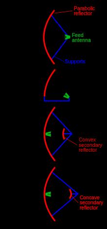
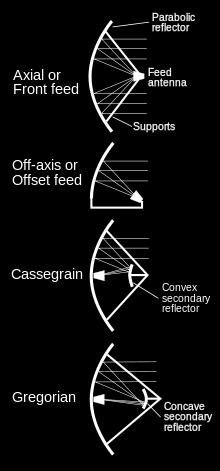
13 Y Y T M eflector ntennas Parabolic reflector antenna with front feed Parabolic reflector antenna with cassegrain feed Corner reflector antenna
14 Y Y T M


15 Y Y T M Frequency independent antennas Log periodic antenna Planar Log periodic slot antenna iscone antenna Log-spiral antenna Various versions of Biconical antennas Infinite Biconical antenna, Finite Biconical antenna, a cone with finite ground, a cone with a stem and discone
16 Y Y T M FUNMENTL PMETE OF NTENN adiation pattern adiation power density adiation intensity ntenna impedance Beamwidth ntenna temperature irectivity Brightness Temperature ntenna efficiency ntenna Factor Gain Bandwidth Group elay Polarization
17 Y T E M Y T E M adiation pattern graphical or mathematical representation of the radiation properties of an antenna such as amplitude, phase, polarization etc as a function of the angular space coordinates θ and Φ. Polar pattern Linear pattern

18 Y Y T M adiation pattern irectional radiation pattern Omni-directional radiation pattern
 Gain is radiation intensity over that of an isotropic source")
19 Y Y T M ame power is radiated adiation intensity is power density over sphere (watt/steradian) Gain is radiation intensity over that of an isotropic source
 eactive near field region (b) adiating")
 region Field regions of an")
20 Y T E M Y T E M Field regions of an antenna (a) eactive near field region (b) adiating near field (Fresnel) region (c) Far field (Fraunhofer) region Field regions of an antenna

21 [ / 2 2 ] Y Y T M
22 Y Y T M adiation power density The time average Poynting vector (average power density) can be written as 1 * W av x, y, z e E H 2 Where W = adiation power density (W/ m 2 ) E = radiated electric field intensity (V/ m) H = radiated magnetic field intensity (/ m)
23 Y Y T M irectivity ()/ irective Gain It can be defined as the ratio of the radiation intensity in a given direction from the antenna to the radiation intensity averaged over all directions U U 0 P rad ( db) 10log U / U P rad [ (dim ensionless )] Where, = directivity (dimensionless) U = radiation intensity (W/ unit solid angle) U 0 = radiation intensity of isotropic source (W/ unit solid angle) P rad = total radiated power (W)
 180 ( ) 180 ( 4 4 For a planar arrays, a better approximation is d d 2 1 0")
24 Y T E M Y T E M r r Where, = directivity (dimensionless) Ω = beam solid angle) θ 1r = HPBW in one plane (radian) θ 2r = HPBW in a plane at a right angle to other (radian) If beamwidth in degrees, equation can be written as: d d d d d d r r ) 180 ( ) 180 ( 4 4 For a planar arrays, a better approximation is d d
25 adiation pattern for a particular paraboloid reflector antenna Y Y T M
 efficiency (dimensionless) e c = conduction efficiency (dimensionless) e d = dielectric efficiency (dimensionless)")
26 Y Y T M ntenna efficiency e 0 e r e e r cd e c e d e 0 (1 )e c d Where, e 0 = total antenna efficiency (dimensionless) e cd = antenna radiation efficiency (dimensionless) : used to relate the gain and directivity e r = reflection (mismatch) efficiency (dimensionless) e c = conduction efficiency (dimensionless) e d = dielectric efficiency (dimensionless) 2

27 Y Y T M Z Z L L Z Z Where, Z L = ntenna impedance Z C = characteristic impedance C C
28 Y Y T M Gain (G)/ Power Gain Gain Gain radiation int ensity total input ( accepted ) power in 4U, (dim ensionless ) P in 4U P, 4U, in P e 4U, ecd ecd (dim ensionless ) Prad 4U, elativegain (dim ensionless ) P ( isotropicsource ) Where, = directivity (dimensionless) U = radiation intensity (W/ unit solid angle) P in = total input power (W) P rad = total radiated power (W) e cd = antenna radiation efficiency (dimensionless) P rad / e cd rad cd P in
29 Y T E M Y T E M The relationship between the gain and the beamwidth of an antenna depends on the distribution of current across the aperture. For a "typical" reflector antenna the following expression is sometimes used: d d G Where, θ 1d = HPBW in one plane (degree) θ 2d = HPBW in a plane at a right angle to other (degree)
30 Y T E M Y T E M Effective perture ( eff ) 2 4 eff G 2 4 e Where, = wavelength = Physical area of the antenna e = antenna aperture efficiency
31 Y T E M Y T E M ntenna can be modeled as an impedance atio of voltage to current at feed port esign antenna to maximize power transfer from transmission line eflection of incident power sets up standing wave Input impedance usually defines antenna bandwidth ntenna Input Impedance
32 Y Y T M Bandwidth Bandwidth of the antenna is defined as the range of frequencies within which the performance of the antenna provides desired characteristics. Generally, Impedance BW when 11-10dB [VW 2] The frequency bandwidth of an antenna can be expressed bsolute Bandwidth (BW) Fractional Bandwidth (FBW). BW FBW 2 f f f H f L Where, f H and f L denote the upper edge and the lower edge of the antenna bandwidth, respectively. For broadband antennas, the bandwidth can also be expressed as the ratio of the upper to the lower frequencies, where the antenna performance is acceptable H H f f L L (2.1)
33 Y Y T M
34 Y Y T M


35 Y Y T M Polarization Polarization is defined as the electric field vector of an antenna oriented in space as a function of time. Electromagnetic Wave (2.1)
36 (2.1) Y Y T M The polarization of a radiated wave is the property of an electromagnetic wave describing the time varying direction and relative magnitude of the electric-field vector at a fixed location in space, and the sense in which it is traced, as observed along the direction of propagation. There are three classifications of antenna polarization: Linear polarization, circular polarization and Elliptical polarization. #Circular and linear polarizations are special cases of elliptical polarization
37 Y Y T M (a) otation of plane electromagnetic wave and (b) its polarization ellipse at z =0 as a function of time
38 Y Y T M Polarisation states for a z-directed plane wave

39 Note : Both the PLF and p lead to the same answers Polarization Loss Factor Y Y T M
40 Y Y T M ntenna Factor The antenna factor is defined as the ratio of the electric field strength to the voltage V (units: V or µv) induced across the terminals of a antenna. For an electric field antenna, the field strength is in units of V/m or µv/m and the resulting antenna factor F is in units of 1/m: F= E incident /V received In a 50 Ω system, the antenna factor is related to the antenna gain G and the wavelength λ via: F= [9.73/ (λ*g 1/2 )]
41 Y Y T M
42 NTENN Most popularly used antennas are: Parabolic eflector ntennas Planar Phased rrays Electronically steered Phased array antennas Y Y T M

43 adar ntenna rchitecture Comparison Y T E M


44 rray adar Passive rray adar ctive rray adar Y T E M

45 ctive Phased rray adar Y T E M
46 igital rray adar rchitecture: igital on eceiver Y T E M Each active analog T/ module is followed by an / for immediate digitization Multiple received beams are formed digitally by the digital beam-former.
47 eference 1. C Balanis, ntenna Theory and esign, 3rd Edition, Wiley, G Kumar and K P ay, Broadband Microstrip ntenna, rctech Publication, K hevgaonkar, Electromagnetic Waves, 2006 Y T E M
Chapter 2. Fundamental Properties of Antennas. ECE 5318/6352 Antenna Engineering Dr. Stuart Long
 Chapter Fundamental Properties of Antennas ECE 5318/635 Antenna Engineering Dr. Stuart Long 1 IEEE Standards Definition of Terms for Antennas IEEE Standard 145-1983 IEEE Transactions on Antennas and Propagation
ANTENNA THEORY. Analysis and Design. CONSTANTINE A. BALANIS Arizona State University. JOHN WILEY & SONS New York Chichester Brisbane Toronto Singapore
 ANTENNA THEORY Analysis and Design CONSTANTINE A. BALANIS Arizona State University JOHN WILEY & SONS New York Chichester Brisbane Toronto Singapore Contents Preface xv Chapter 1 Antennas 1 1.1 Introduction
HHTEHHH THEORY ANALYSIS AND DESIGN. CONSTANTINE A. BALANIS Arizona State University
 HHTEHHH THEORY ANALYSIS AND DESIGN CONSTANTINE A. BALANIS Arizona State University JOHN WILEY & SONS, INC. New York Chichester Brisbane Toronto Singapore Contents Preface V CHAPTER 1 ANTENNAS 1.1 Introduction
ANTENNAS AND WAVE PROPAGATION EC602
 ANTENNAS AND WAVE PROPAGATION EC602 B.Tech Electronics & Communication Engineering, Semester VI INSTITUTE OF TECHNOLOGY NIRMA UNIVERSITY 1 Lesson Planning (L-3,P-2,C-4) Chapter No. Name Hours 1. Basic
Notes 21 Introduction to Antennas
 ECE 3317 Applied Electromagnetic Waves Prof. David R. Jackson Fall 018 Notes 1 Introduction to Antennas 1 Introduction to Antennas Antennas An antenna is a device that is used to transmit and/or receive
Antenna Fundamentals Basics antenna theory and concepts
 Antenna Fundamentals Basics antenna theory and concepts M. Haridim Brno University of Technology, Brno February 2017 1 Topics What is antenna Antenna types Antenna parameters: radiation pattern, directivity,
ANTENNA THEORY ANALYSIS AND DESIGN
 ANTENNA THEORY ANALYSIS AND DESIGN THIRD EDITION Constantine A. Balanis WILEY- INTERSCIENCE A JOHN WILEY & SONS. INC.. PUBLICATION ial iel pi ial ial ial IBl ial ial ial pi Sl Contents Preface Xlll 1 Antennas
EC ANTENNA AND WAVE PROPAGATION
 EC6602 - ANTENNA AND WAVE PROPAGATION FUNDAMENTALS PART-B QUESTION BANK UNIT 1 1. Define the following parameters w.r.t antenna: i. Radiation resistance. ii. Beam area. iii. Radiation intensity. iv. Directivity.
RADIATION PATTERNS. The half-power (-3 db) beamwidth is a measure of the directivity of the antenna.
 beamwidth is a measure of the directivity of the antenna.") RADIATION PATTERNS The radiation pattern is a graphical depiction of the relative field strength transmitted from or received by the antenna. Antenna radiation patterns are taken at one frequency, one
RADIATION PATTERNS The radiation pattern is a graphical depiction of the relative field strength transmitted from or received by the antenna. Antenna radiation patterns are taken at one frequency, one
ELEG 648 Radiation/Antennas I. Mark Mirotznik, Ph.D. Associate Professor The University of Delaware
 ELEG 648 Radiation/Antennas I Mark Mirotznik Ph.D. Associate Professor The University of Delaware A jk rr ' e ' r J r dv ' 4 r r ' F If we have magnetic sources jk rr ' e ' r M r dv ' 4 r r ' Field
S=E H ANTENNA RADIATION
 ANTENNA RADIATION Antennas radiate spherical waves that propagate in the radial direction for a coordinate system centered on the antenna. At large distances, spherical waves can be approx imated by plane
BHARATHIDASAN ENGINEERING COLLEGE NATTARAMPALLI Frequently Asked Questions (FAQ) Unit 1
 Unit 1") BHARATHIDASAN ENGINEERING COLLEGE NATTARAMPALLI 635854 Frequently Asked Questions (FAQ) Unit 1 Degree / Branch : B.E / ECE Sem / Year : 3 rd / 6 th Sub Name : Antennas & Wave Propagation Sub Code : EC6602
BHARATHIDASAN ENGINEERING COLLEGE NATTARAMPALLI 635854 Frequently Asked Questions (FAQ) Unit 1 Degree / Branch : B.E / ECE Sem / Year : 3 rd / 6 th Sub Name : Antennas & Wave Propagation Sub Code : EC6602
Antenna Theory. Introduction
 1 Introduction Antenna Theory Antennas are device that designed to radiate electromagnetic energy efficiently in a prescribed manner. It is the current distributions on the antennas that produce the radiation.
ANTENNA INTRODUCTION / BASICS
 ANTENNA INTRODUCTION / BASICS RULES OF THUMB: 1. The Gain of an antenna with losses is given by: 2. Gain of rectangular X-Band Aperture G = 1.4 LW L = length of aperture in cm Where: W = width of aperture
An Introduction to Antennas
 May 11, 010 An Introduction to Antennas 1 Outline Antenna definition Main parameters of an antenna Types of antennas Antenna radiation (oynting vector) Radiation pattern Far-field distance, directivity,
Introduction to Radar Systems. Radar Antennas. MIT Lincoln Laboratory. Radar Antennas - 1 PRH 6/18/02
 Introduction to Radar Systems Radar Antennas Radar Antennas - 1 Disclaimer of Endorsement and Liability The video courseware and accompanying viewgraphs presented on this server were prepared as an account
Antennas 1. Antennas
 Antennas Antennas 1! Grading policy. " Weekly Homework 40%. " Midterm Exam 30%. " Project 30%.! Office hour: 3:10 ~ 4:00 pm, Monday.! Textbook: Warren L. Stutzman and Gary A. Thiele, Antenna Theory and
Simulation Results of Circular Horn Antenna
 Simulation Results of Circular Horn Antenna Mahendra Singh Meena 1, Ved Prakash 2 1Assistant Professor, Amity University Haryana, Panchgaon, Manesar, Gurgaon, Haryana, India 2Ved Prakash, Amity University
Antenna Theory and Design
 Antenna Theory and Design SECOND EDITION Warren L. Stutzman Gary A. Thiele WILEY Contents Chapter 1 Antenna Fundamentals and Definitions 1 1.1 Introduction 1 1.2 How Antennas Radiate 4 1.3 Overview of
Antenna Fundamentals. Microwave Engineering EE 172. Dr. Ray Kwok
 Antenna Fundamentals Microwave Engineering EE 172 Dr. Ray Kwok Reference Antenna Theory and Design Warran Stutzman, Gary Thiele, Wiley & Sons (1981) Microstrip Antennas Bahl & Bhartia, Artech House (1980)
CHAPTER 5 THEORY AND TYPES OF ANTENNAS. 5.1 Introduction
 CHAPTER 5 THEORY AND TYPES OF ANTENNAS 5.1 Introduction Antenna is an integral part of wireless communication systems, considered as an interface between transmission line and free space [16]. Antenna
EMG4066:Antennas and Propagation Exp 1:ANTENNAS MMU:FOE. To study the radiation pattern characteristics of various types of antennas.
 OBJECTIVES To study the radiation pattern characteristics of various types of antennas. APPARATUS Microwave Source Rotating Antenna Platform Measurement Interface Transmitting Horn Antenna Dipole and Yagi
Chapter 1 - Antennas
 EE 483/583/L Antennas for Wireless Communications 1 / 8 1.1 Introduction Chapter 1 - Antennas Definition - That part of a transmitting or receiving system that is designed to radiate or to receive electromagnetic
Antenna & Propagation. Antenna Parameters
 For updated version, please click on http://ocw.ump.edu.my Antenna & Propagation Antenna Parameters by Nor Hadzfizah Binti Mohd Radi Faculty of Electric & Electronics Engineering hadzfizah@ump.edu.my Chapter
ANTENNA INTRODUCTION / BASICS
 Rules of Thumb: 1. The Gain of an antenna with losses is given by: G 0A 8 Where 0 ' Efficiency A ' Physical aperture area 8 ' wavelength ANTENNA INTRODUCTION / BASICS another is:. Gain of rectangular X-Band
Antenna Engineering Lecture 3: Basic Antenna Parameters
 Antenna Engineering Lecture 3: Basic Antenna Parameters ELC 405a Fall 2011 Department of Electronics and Communications Engineering Faculty of Engineering Cairo University 2 Outline 1 Radiation Pattern
SI TECHNICAL 2018 UNIT IV QUESTION BANK
 SI TECHNICAL 2018 UNIT IV QUESTION BANK 1. In what range of frequencies are most omnidirectional horizontally polarized antennas used? A. VHF, UHF B. VLF, LF C. SH, EHF D. MF, HF 2. If the current ratios
( ) 2 ( ) 3 ( ) + 1. cos! t " R / v p 1 ) H =! ˆ" I #l ' $ 2 ' 2 (18.20) * + ! ˆ& "I #l ' $ 2 ' , ( βr << 1. "l ' E! ˆR I 0"l ' cos& + ˆ& 0
 2 ( ) 3 ( ) + 1. cos! t R / v p 1 ) H =! ˆ I #l ' $ 2 ' 2 (18.20) * + ! ˆ& I #l ' $ 2 ' , ( βr << 1. l ' E! ˆR I 0l ' cos& + ˆ& 0") Summary Chapter 8. This last chapter treats the problem of antennas and radiation from antennas. We start with the elemental electric dipole and introduce the idea of retardation of potentials and fields
Summary Chapter 8. This last chapter treats the problem of antennas and radiation from antennas. We start with the elemental electric dipole and introduce the idea of retardation of potentials and fields
Antennas Prof. Girish Kumar Department of Electrical Engineering India Institute of Technology, Bombay. Module - 1 Lecture - 1 Antennas Introduction-I
 Antennas Prof. Girish Kumar Department of Electrical Engineering India Institute of Technology, Bombay Module - 1 Lecture - 1 Antennas Introduction-I Hello everyone. Welcome to the exciting world of antennas.
Travelling Wave, Broadband, and Frequency Independent Antennas. EE-4382/ Antenna Engineering
 Travelling Wave, Broadband, and Frequency Independent Antennas EE-4382/5306 - Antenna Engineering Outline Traveling Wave Antennas Introduction Traveling Wave Antennas: Long Wire, V Antenna, Rhombic Antenna
UNIT Explain the radiation from two-wire. Ans: Radiation from Two wire
 UNIT 1 1. Explain the radiation from two-wire. Radiation from Two wire Figure1.1.1 shows a voltage source connected two-wire transmission line which is further connected to an antenna. An electric field
Introduction to Antennas
 Dr. S. X-ol What is an antenna? Introduction to ntennas n antenna is a passive structurethat serves as transition between a transmission lineand airused to transmit and/or receive electromagnetic waves.
Design of Linearly Polarized Rectangular Microstrip Patch Antenna for GPS Applications at MHz
 Design of Linearly Polarized Rectangular Microstrip Patch Antenna for GPS Applications at 1575.4MHz P. S. S. Pavan Ganesh Associate Professor, Sreyas Institute of Engineering and Technology, Hyderabad
What does reciprocity mean
 Antennas Definition of antenna: A device for converting electromagnetic radiation in space into electrical currents in conductors or vice-versa. Radio telescopes are antennas Reciprocity says we can treat
Broadband Dual Polarized Space-Fed Antenna Arrays with High Isolation
 Progress In Electromagnetics Research C, Vol. 55, 105 113, 2014 Broadband Dual Polarized Space-Fed Antenna Arrays with High Isolation Prashant K. Mishra 1, *, Dhananjay R. Jahagirdar 1,andGirishKumar 2
KINGS COLLEGE OF ENGINEERING DEPARTMENT OF ELECTRONICS AND COMMUNICATION ENGINEERING QUESTION BANK
 KINGS COLLEGE OF ENGINEERING DEPARTMENT OF ELECTRONICS AND COMMUNICATION ENGINEERING QUESTION BANK SUB.NAME : ANTENNAS & WAVE PROPAGATION SUB CODE : EC 1352 YEAR : III SEMESTER : VI UNIT I: ANTENNA FUNDAMENTALS
ANTENNAS FROM THEORY TO PRACTICE WILEY. Yi Huang University of Liverpool, UK. Kevin Boyle NXP Semiconductors, UK
 ANTENNAS FROM THEORY TO PRACTICE Yi Huang University of Liverpool, UK Kevin Boyle NXP Semiconductors, UK WILEY A John Wiley and Sons, Ltd, Publication Contents Preface Acronyms and Constants xi xiii 1
Practical Antennas and. Tuesday, March 4, 14
 Practical Antennas and Transmission Lines Goals Antennas are the interface between guided waves (from a cable) and unguided waves (in space). To understand the various properties of antennas, so as to
Half-Wave Dipole. Radiation Resistance. Antenna Efficiency
 Antennas Simple Antennas Isotropic radiator is the simplest antenna mathematically Radiates all the power supplied to it, equally in all directions Theoretical only, can t be built Useful as a reference:
Antennas and Propagation. Chapter 4: Antenna Types
 Antennas and Propagation : Antenna Types 4.4 Aperture Antennas High microwave frequencies Thin wires and dielectrics cause loss Coaxial lines: may have 10dB per meter Waveguides often used instead Aperture
KINGS COLLEGE OF ENGINEERING. DEPARTMENT OF ELECTRONICS AND COMMUNICATION ENGINEERING Academic Year (Even Sem) QUESTION BANK (AUTT-R2008)
 QUESTION BANK (AUTT-R2008)") KINGS COLLEGE OF ENGINEERING DEPARTMENT OF ELECTRONICS AND COMMUNICATION ENGINEERING Academic Year 2012-2013(Even Sem) QUESTION BANK (AUTT-R2008) SUBJECT CODE /NAME: EC 1352 / ANTENNEA AND WAVE PROPAGATION
KINGS COLLEGE OF ENGINEERING DEPARTMENT OF ELECTRONICS AND COMMUNICATION ENGINEERING Academic Year 2012-2013(Even Sem) QUESTION BANK (AUTT-R2008) SUBJECT CODE /NAME: EC 1352 / ANTENNEA AND WAVE PROPAGATION
DEPARTMENT OF ELECTRONICS & COMMUNICATION ENGINEERING SUBJECT NAME:
 Chendu College of Engineering & Technology (Approved by AICTE, New Delhi and Affiliated to Anna University) Zamin Endathur, Madurantakam, Kancheepuram, District 603311. DEPARTMENT OF ELECTRONICS & COMMUNICATION
Antenna Parameters. Ranga Rodrigo. University of Moratuwa. December 15, 2008
 Antenna Parameters Ranga Rodrigo University of Moratuwa December 15, 2008 Ranga Rodrigo (University of Moratuwa) Antenna Parameters December 15, 2008 1 / 47 Summary of Last Week s Lecture 90 o Radiation
Continuous Arrays Page 1. Continuous Arrays. 1 One-dimensional Continuous Arrays. Figure 1: Continuous array N 1 AF = I m e jkz cos θ (1) m=0
 m=0") Continuous Arrays Page 1 Continuous Arrays 1 One-dimensional Continuous Arrays Consider the 2-element array we studied earlier where each element is driven by the same signal (a uniform excited array),
Continuous Arrays Page 1 Continuous Arrays 1 One-dimensional Continuous Arrays Consider the 2-element array we studied earlier where each element is driven by the same signal (a uniform excited array),
The magnetic surface current density is defined in terms of the electric field at an aperture as follows: 2E n (6.1)
") Chapter 6. Aperture antennas Antennas where radiation occurs from an open aperture are called aperture antennas. xamples include slot antennas, open-ended waveguides, rectangular and circular horn antennas,
Chapter 6. Aperture antennas Antennas where radiation occurs from an open aperture are called aperture antennas. xamples include slot antennas, open-ended waveguides, rectangular and circular horn antennas,
Antennas & wave Propagation ASSIGNMENT-I
 Shri Vishnu Engineering College for Women :: Bhimavaram Department of Electronics & Communication Engineering Antennas & wave Propagation 1. Define the terms: i. Antenna Aperture ii. Beam Width iii. Aperture
ANTENNAS & WAVE PROPAGATION
 ANTENNAS & WAVE PROPAGATION R13 III B Tech I SEMESTER 1 III Year I SEMESTER T P C 3+1 0 3 ANTENNAS AND WAVE PROPAGATION OBJECTIVES UNIT I ANTENNA FUNDAMENTALS: Introduction, Radiation Mechanism single
INSTITUTE OF AERONAUTICAL ENGINEERING Dundigal, Hyderabad ELECTRONICS AND COMMUNIACTION ENGINEERING QUESTION BANK
 INSTITUTE OF AERONAUTICAL ENGINEERING Dundigal, Hyderabad - 500 04 ELECTRONICS AND COMMUNIACTION ENGINEERING QUESTION BANK Course Name : Antennas and Wave Propagation (AWP) Course Code : A50418 Class :
Microstrip Antennas Integrated with Horn Antennas
 53 Microstrip Antennas Integrated with Horn Antennas Girish Kumar *1, K. P. Ray 2 and Amit A. Deshmukh 1 1. Department of Electrical Engineering, I.I.T. Bombay, Powai, Mumbai 400 076, India Phone: 91 22
Broadband and High Efficiency Single-Layer Reflectarray Using Circular Ring Attached Two Sets of Phase-Delay Lines
 Progress In Electromagnetics Research M, Vol. 66, 193 202, 2018 Broadband and High Efficiency Single-Layer Reflectarray Using Circular Ring Attached Two Sets of Phase-Delay Lines Fei Xue 1, *, Hongjian
ANT6: The Half-Wave Dipole Antenna
 In this lecture, we simplify the space radiating current analysis to include the special (but very important) case of the general wire antenna. Concentrating on results for the half-wave dipole, we demonstrate
Antenna Design: Simulation and Methods
 Antenna Design: Simulation and Methods Radiation Group Signals, Systems and Radiocommunications Department Universidad Politécnica de Madrid Álvaro Noval Sánchez de Toca e-mail: anoval@gr.ssr.upm.es Javier
Topic 3. Fundamental Parameters of Antennas. Tamer Abuelfadl
 Topic 3 Fundamental Parameters of Antennas Tamer Abuelfadl Electronics and Electrical Communications Department Faculty of Engineering Cairo University Tamer Abuelfadl (EEC, Cairo University) Topic 3 ELC
Dr. John S. Seybold. November 9, IEEE Melbourne COM/SP AP/MTT Chapters
 Antennas Dr. John S. Seybold November 9, 004 IEEE Melbourne COM/SP AP/MTT Chapters Introduction The antenna is the air interface of a communication system An antenna is an electrical conductor or system
A N T E N N A. Tracking Radar I E O T R Y & D E G N
 racking adar racking Functions and Parameter stimation adar Parameter stimation Location zimuth ngle levation ngle ange Motion adial Velocity adial cceleration otation ize mplitude (C) adial xtent (Length)
Monopole Antennas. Prof. Girish Kumar Electrical Engineering Department, IIT Bombay. (022)
") Monopole Antennas Prof. Girish Kumar Electrical Engineering Department, IIT Bombay gkumar@ee.iitb.ac.in (022) 2576 7436 Monopole Antenna on Infinite Ground Plane Quarter-wavelength monopole Antenna on
Monopole Antennas Prof. Girish Kumar Electrical Engineering Department, IIT Bombay gkumar@ee.iitb.ac.in (022) 2576 7436 Monopole Antenna on Infinite Ground Plane Quarter-wavelength monopole Antenna on
Newsletter 5.4. New Antennas. The profiled horns. Antenna Magus Version 5.4 released! May 2015
 Newsletter 5.4 May 215 Antenna Magus Version 5.4 released! Version 5.4 sees the release of eleven new antennas (taking the total number of antennas to 277) as well as a number of new features, improvements
COUPLED SECTORIAL LOOP ANTENNA (CSLA) FOR ULTRA-WIDEBAND APPLICATIONS *
 FOR ULTRA-WIDEBAND APPLICATIONS *") COUPLED SECTORIAL LOOP ANTENNA (CSLA) FOR ULTRA-WIDEBAND APPLICATIONS * Nader Behdad, and Kamal Sarabandi Department of Electrical Engineering and Computer Science University of Michigan, Ann Arbor, MI,
COUPLED SECTORIAL LOOP ANTENNA (CSLA) FOR ULTRA-WIDEBAND APPLICATIONS * Nader Behdad, and Kamal Sarabandi Department of Electrical Engineering and Computer Science University of Michigan, Ann Arbor, MI,
Fundamentals of UWB antenna
 Chapter 2 Fundamentals of UWB antenna An overview of UWB Technology was given in Chapter 1. The objective of the thesis as already enunciated is to design antennas for UWB applications. In this chapter
Diseño de antenas de ranura de doble banda en tecnología inverted microstrip gap waveguide de bajo coste
 Universidad Carlos III de Madrid Repositorio institucional e-archivo Trabajos académicos http://e-archivo.uc3m.es Trabajos Fin de Grado Escuela Politécnica Superior 2015 Diseño de antenas de ranura de
Newsletter 3.1. Antenna Magus version 3.1 released! New antennas in the database. Square pin-fed septum horn. July 2011
 Newsletter 3.1 July 2011 Antenna Magus version 3.1 released! Antenna Magus 3.0 was such a feature laden release that not all of the new features could be mentioned in the newsletter, so we decided to rather
Electrically Reconfigurable Radiation Patterns of Slot Antenna Array Using Agile Plasma Wall
 Progress In Electromagnetics Research C, Vol. 73, 75 80, 2017 Electrically Reconfigurable Radiation Patterns of Slot Antenna Array Using Agile Plasma Wall Oumar A. Barro *, Mohammed Himdi, and Alexis Martin
KULLIYYAH OF ENGINEERING
 KULLIYYAH OF ENGINEERING DEPARTMENT OF ELECTRICAL & COMPUTER ENGINEERING ANTENNA AND WAVE PROPAGATION LABORATORY (ECE 4103) EXPERIMENT NO 3 RADIATION PATTERN AND GAIN CHARACTERISTICS OF THE DISH (PARABOLIC)
 VALLIAMMAI ENGINEERING COLLEGE SRM Nagar, Kattankulathur 603 203. DEPARTMENT OF ELECTRONICS & COMMUNICATION ENGINEERING QUESTION BANK SUBJECT : EC6602 ANTENNA AND WAVE PROPOGATION SEM / YEAR : VI / III
Antenna Theory and Design
 Antenna Theory and Design Antenna Theory and Design Associate Professor: WANG Junjun 王珺珺 School of Electronic and Information Engineering, Beihang University wangjunjun@buaa.edu.cn 13426405497 Chapter
CREATING THREE DUAL ISOSCELES TRIANGULAR SLOTS ON THE PATCH AND BANDWIDTH ENHANCEMENT FOR SLOTTED METAMATERIAL MICROSTRIP PATCH ANTENNA
 CREATING THREE DUAL ISOSCELES TRIANGULAR SLOTS ON THE PATCH AND BANDWIDTH ENHANCEMENT FOR SLOTTED METAMATERIAL MICROSTRIP PATCH ANTENNA BUDIPUTI ANITHA PRAVALLI, M. Tech, ASSISTANT PROFESSOR SRK INSTITUTE
S.R.M. Institute of Science & Technology Deemed University School of Electronics & Communication Engineering
 S.R.M. Institute of Science & Technology Deemed University School of Electronics & Communication Engineering Question Bank Subject Code : EC401 Subject Name : Antennas and Wave Propagation Year & Sem :
CHAPTER 2 MICROSTRIP REFLECTARRAY ANTENNA AND PERFORMANCE EVALUATION
 43 CHAPTER 2 MICROSTRIP REFLECTARRAY ANTENNA AND PERFORMANCE EVALUATION 2.1 INTRODUCTION This work begins with design of reflectarrays with conventional patches as unit cells for operation at Ku Band in
IMPROVEMENT OF YAGI UDA ANTENNA RADIATION PATTERN
 International Journal of Mechanical Engineering and Technology (IJMET) Volume 8, Issue 7, July 2017, pp. 636 641, Article ID: IJMET_08_07_071 Available online at http://www.iaeme.com/ijmet/issues.asp?jtype=ijmet&vtype=8&itype=7
A LABORATORY COURSE ON ANTENNA MEASUREMENT
 A LABORATORY COURSE ON ANTENNA MEASUREMENT Samuel Parker Raytheon Systems Company, 2000 East Imperial Highway RE/R02/V509, El Segundo, CA 90245 Dean Arakaki Electrical Engineering Department, California
Broadband Circular Polarized Antenna Loaded with AMC Structure
 Progress In Electromagnetics Research Letters, Vol. 76, 113 119, 2018 Broadband Circular Polarized Antenna Loaded with AMC Structure Yi Ren, Xiaofei Guo *,andchaoyili Abstract In this paper, a novel broadband
Theory of Antennas, Its Advantage & Applications in Communication Systems
 Theory of Antennas, Its Advantage & Applications in Communication Systems 1 Dr. Sumit Kumar Gupta, 2 Harish Kumar Jangam, 3 Nipun Sharma, 1 Assistant Professor, 2,3, Research Scholar Department of Physics
DESIGN OF PRINTED YAGI ANTENNA WITH ADDI- TIONAL DRIVEN ELEMENT FOR WLAN APPLICA- TIONS
 Progress In Electromagnetics Research C, Vol. 37, 67 81, 013 DESIGN OF PRINTED YAGI ANTENNA WITH ADDI- TIONAL DRIVEN ELEMENT FOR WLAN APPLICA- TIONS Jafar R. Mohammed * Communication Engineering Department,
ELEC 425 Interference Control in Electronics Lecture 7(a) Introduction to Antennas: Terminology
 Introduction to Antennas: Terminology") Dr. Gregory J. Mazzaro Fall 017 ELEC 45 Interference Control in Electronics Lecture 7(a) Introduction to Antennas: Terminology Chapter 9 THE CITADEL, THE MILITARY COLLEGE OF SOUTH CAROLINA 171 Moultrie
Dr. Gregory J. Mazzaro Fall 017 ELEC 45 Interference Control in Electronics Lecture 7(a) Introduction to Antennas: Terminology Chapter 9 THE CITADEL, THE MILITARY COLLEGE OF SOUTH CAROLINA 171 Moultrie
LECTURE 4: Fundamental Antenna Parameters 1. Radiation Pattern Note:
 LECTURE 4: Fundamental Antenna Parameters (Radiation pattern. Pattern beamwidths. Radiation intensity. Directivity. Gain. Antenna efficiency and radiation efficiency. Frequency bandwidth. Input impedance
Note: For. interested in. Radiation. A field pattern. H and a phase
 Lecture-3 Antenna parameters: (Continued ) 1.4.3 Radiated Power With this information, now we are in a position to calculate the total radiated power from an antenna. Mathematically it can be written as
Antenna & Wave Propagation (Subject Code: 7EC1)
") COMPUCOM INSTITUTE OF TECHNOLOGY & MANAGEMENT, JAIPUR (DEPARTMENT OF ELECTRONICS & COMMUNICATION) Notes Antenna & Wave Propagation (Subject Code: 7EC1) Prepared By: Raj Kumar Jain Class: B. Tech. IV Year,
COMPUCOM INSTITUTE OF TECHNOLOGY & MANAGEMENT, JAIPUR (DEPARTMENT OF ELECTRONICS & COMMUNICATION) Notes Antenna & Wave Propagation (Subject Code: 7EC1) Prepared By: Raj Kumar Jain Class: B. Tech. IV Year,
Design of a 915 MHz Patch Antenna with structure modification to increase bandwidth
 Fidel Amezcua Professor: Ray Kwok Electrical Engineering 172 28 May 2010 Design of a 915 MHz Patch Antenna with structure modification to increase bandwidth 1. Introduction The objective presented in this
Antennas and Propagation. Chapter 1: Introduction
 Antennas and Propagation : Introduction History of Antennas and Propagation Timeline 1870 Maxwell s Equations 80 Heinrich Hertz s Loop Experiment (1886) 90 1900 Guglielmo Marconi (1901) Transatlantic Transmission
NOVEL DESIGN BROADBAND CPW-FED MONOPOLE ANTENNA WITH TRAPEZIUM SHAPED-STUB FOR COMMUNICATION SYSTEM
 NOVEL DESIGN BROADBAND CPW-FED MONOPOLE ANTENNA WITH TRAPEZIUM SHAPED-STUB FOR COMMUNICATION SYSTEM Karim A. Hamad Department of Electronic and Communication, College of Engineering, AL-Nahrain University,
A Simple Introduction to Antennas
 Appendix A A Simple Introduction to Antennas A.1 Introduction: Radiation Resistance and Radiation Patterns An antenna is a transitional device, or transducer, that forms an interface for energy traveling
Design of a UHF Pyramidal Horn Antenna Using CST
 Volume 114 No. 7 2017, 447-457 ISSN: 1311-8080 (printed version); ISSN: 1314-3395 (on-line version) url: http://www.ijpam.eu ijpam.eu Design of a UHF Pyramidal Horn Antenna Using CST Biswa Ranjan Barik
Aperture Antennas. Reflectors, horns. High Gain Nearly real input impedance. Huygens Principle
 Antennas 97 Aperture Antennas Reflectors, horns. High Gain Nearly real input impedance Huygens Principle Each point of a wave front is a secondary source of spherical waves. 97 Antennas 98 Equivalence
In this lecture, we study the general case of radiation from z-directed spatial currents. The far-
 In this lecture, we study the general case of radiation from z-directed spatial currents. The far- field radiation equations that result from this treatment form some of the foundational principles of
Evangelos Kranakis, School of Computer Science, Carleton University, Ottawa 1. Antennae Basics
 Evangelos Kranakis, School of Computer Science, Carleton University, Ottawa 1 Antennae Basics Evangelos Kranakis, School of Computer Science, Carleton University, Ottawa 2 Essentials Antennae Examples
Performance Analysis of Different Ultra Wideband Planar Monopole Antennas as EMI sensors
 International Journal of Electronics and Communication Engineering. ISSN 09742166 Volume 5, Number 4 (2012), pp. 435445 International Research Publication House http://www.irphouse.com Performance Analysis
10 Antenna gain, beam pattern, directivity
 10 Antenna gain, beam pattern, directivity Adipoleantenna(oracloselyrelatedmonopoletobestudiedinLecture 18) is a near perfect radiator for purposes of broadcasting that is, sending waves of equal amplitudes
Newsletter 4.4. Antenna Magus version 4.4 released! Array synthesis reflective ground plane addition. July 2013
 Newsletter 4.4 July 2013 Antenna Magus version 4.4 released! We are pleased to announce the new release of Antenna Magus Version 4.4. This release sees the addition of 5 new antennas: Horn-fed truncated
RF AND MICROWAVE ENGINEERING
 RF AND MICROWAVE ENGINEERING FUNDAMENTALS OF WIRELESS COMMUNICATIONS Frank Gustrau Dortmund University of Applied Sciences and Arts, Germany WILEY A John Wiley & Sons, Ltd., Publication Preface List of
MARIA COLLEGE OF ENGINEERING AND TECHNOLOGY, ATTOOR
 MARIA COLLEGE OF ENGINEERING AND TECHNOLOGY, ATTOOR DEPARTMENT OF ELECTRONICS AND COMMUNICATION ENGINEERING ANTENNAS AND WAVE PROPOGATION 2 MARKS QUESTIONS & ANSWERS 1. Define an antenna. Unit.1 Antenna
Unit 4. Antenna Theory
 Unit 4. Antenna Theory A person, who needs to convey a thought, an idea or a doubt, can do so by voice communication. The following illustration shows two individuals communicating with each other. Here,
YAGI-UDA DESIGN OF U.H.F BAND AERIAL TO SUIT LOCAL TV STATIONS
 YAGI-UDA DESIGN OF U.H.F BAND AERIAL TO SUIT LOCAL TV STATIONS PROJECT INDEX: PRJ 079 Presented By: GITAU SIMON WAWERU F17/8261/2004 Supervisor: Mr. S.L OGABA Examiner: Mr. OMBURA Objective The main objective
Characteristics of Biconical Antennas Used for EMC Measurements
 Advance Topics in Electromagnetic Compatibility Characteristics of Biconical Antennas Used for EMC Measurements Mohsen Koohestani koohestani.mohsen@epfl.ch Outline State-of-the-art of EMC Antennas Biconical
Exercise 1-3. Radar Antennas EXERCISE OBJECTIVE DISCUSSION OUTLINE DISCUSSION OF FUNDAMENTALS. Antenna types
 Exercise 1-3 Radar Antennas EXERCISE OBJECTIVE When you have completed this exercise, you will be familiar with the role of the antenna in a radar system. You will also be familiar with the intrinsic characteristics
HYBRID ARRAY ANTENNA FOR BROADBAND MILLIMETER-WAVE APPLICATIONS
 Progress In Electromagnetics Research, PIER 83, 173 183, 2008 HYBRID ARRAY ANTENNA FOR BROADBAND MILLIMETER-WAVE APPLICATIONS S. Costanzo, I. Venneri, G. Di Massa, and G. Amendola Dipartimento di Elettronica,
DESIGN OF A NOVEL STEPPED BICONICAL ANTENNA Yashu Sindhwani 1, Er. Manish Mehta 2, Himanshu Monga 3
 DESIGN OF A NOVEL STEPPED BICONICAL ANTENNA Yashu Sindhwani 1, Er. Manish Mehta 2, Himanshu Monga 3 1 Jan Nayak Ch. Devi lal Vidyapeeth, Sirsa, Haryana 2 HOD Jan Nayak Ch. Devi Lal Vidyapeeth, Sirsa, Haryana
Chapter 6 Broadband Antenna. 1. Loops antenna 2. Heliksantenna 3. Yagi uda antenna
 Chapter 6 Broadband Antenna 1. Loops antenna 2. Heliksantenna 3. Yagi uda antenna 1 Design A broadband antenna should have acceptable performance (determined by its pattern, gain and/or feed-point impedance)
Kamal M. Abood, Moretadha J. Kadhim, Mohammed I. Abd-Almajied, and Zinah F. Kadhim
 International Journal of Scientific & Engineering Research, Volume 5, Issue 9, September-2014 899 Improvement for Radio Jove Telescope Antenna Using Directive Angle Yagi Kamal M. Abood, Moretadha J. Kadhim,
Design of 2 1 Square Microstrip Antenna Array
 International Journal of Engineering and Manufacturing Science. ISSN 2249-3115 Volume 8, Number 1 (2018) pp. 89-94 Research India Publications http://www.ripublication.com Design of 2 1 Square Microstrip
THROUGHOUT the last several years, many contributions
 244 IEEE ANTENNAS AND WIRELESS PROPAGATION LETTERS, VOL. 6, 2007 Design and Analysis of Microstrip Bi-Yagi and Quad-Yagi Antenna Arrays for WLAN Applications Gerald R. DeJean, Member, IEEE, Trang T. Thai,