Antenna Theory. Introduction
|
|
|
- Cecily Baker
- 6 years ago
- Views:
Transcription
1 1 Introduction Antenna Theory Antennas are device that designed to radiate electromagnetic energy efficiently in a prescribed manner. It is the current distributions on the antennas that produce the radiation. Usually this current distributions are excited by transmission lines and waveguides. Transmission line Antenna Current distributions

2 Propagation mode adapter During both transmission and receive operations the antenna must provide the transition between these two propagation modes. 2
3 Transmitting Antenna Equivalent Circuit Transmitter Antenna Transm. line Radio wave Transmission-line Thevenin equivalent circuit of a radiating (transmitting) system. The antenna is represented by its input impedance (which is frequency-dependent and is influenced by objects nearby) as seen from the generator V g - voltage-source generator (transmitter); Z g - impedance of the generator (transmitter); R rad - radiation resistance, represents energy radiated into space (related to the radiated power as) P rad = I 2 A R rad R L - loss resistance, (related to conduction and dielectric losses); i.e. transformed into heat in the antenna structure jx A antenna reactance. ZA=Antenna impedance: Z A =R rad +R L +jx A

4 Receiving Antenna Equivalent Circuit Antenna Radio wave Transm.line Receiver Transmission-line Thevenin equivalent circuit of a receiving antenna system. Note: The antenna impedance is the same when the antenna is used to radiate and when it is used to receive energy
5 Frequencies & Wavelengths After Kraus & Marhefka, 2003
6 RF Bands, Names & Users After Kraus & Marhefka, 2003


7 Theory Antennas include wire and aperture types. Wire types include dipoles, monopoles, loops, rods, stubs, helicies, Yagi-Udas, spirals. Aperture types include horns, reflectors, parabolic, lenses. 7

8 Theory In wire-type antennas the radiation characteristics are determined by the current distribution which produces the local magnetic field. Yagi-Uda antenna Helical antenna 8

9 Theory wire antenna example Some simplifying approximations can be made to take advantage the far-field conditions. 9
10 10 Theory wire antenna example Once E q and E f are known, the radiation characteristics can be determined. Defining the directional function f (q, f) from
11 What makes a short dipole? Length l is very short compared to wavelength (l<<, i.e l should not exceed /50) which is also called Hertzian dipole. Carries uniform current I along the entire length l. To allow such uniform current, we attach plates at the ends of the dipole as capacitive load. However, we assume the plates are small that their radiation is negligible. The dipole may be energized by balanced transmission line. However, it is assumed that the transmission line does not radiate. The diameter d of the dipole is small compared to its length (d<<l, ). Thus a short dipole consist a simple of a thin conductor of length L with a uniform current I and point charges q at the ends. dq dt I I +q -q L
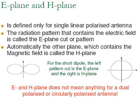
12 Wire antenna (half wave dipole) The most basic form of antenna, and most popular Transmission line /2 Total length of the radiating element is halfwavelength Radiation pattern of a 2 thin wire dipole omnidirectional E-plane H-plane
13 Quarter wave monopole 1. A quarter-wave monopole antenna excited by a source at its base exhibits the same radiation pattern in the region above the ground plane as a halfwave dipole in free space 2. Use image theory for analysis 3. Hence, a monopole radiates only half as much power as the dipole.
14 Monopole antenna Ground plane q q Mirroring principle creates image of monopole, transforming it into a dipole Radition pattern of vertical monopole above ground of (A) perfect and (B) average conductivity 14

15 Ground plane A ground plane will produce an image of nearby currents. The image will have a phase shift of 180 with respect to the original current. Therefore as the current element is placed close to the surface, the induced image current will effectively cancel the radiating fields from the current. The ground plane may be any conducting surface including a metal sheet, a water surface, or the ground (soil, pavement, rock). Horizontal current element Conducting surface (ground plane) Current element image 15
16 Dipole of other lengths
17
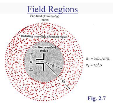
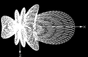
18 Field regions Radiating near field (Fresnel) region antenna No abrupt changes in the field configurations are noted as the boundaries are crossed but there are distinct differences between the fields Reactive near field region Far field (Fraunhofer) region
19
20 Energy is transferred to and from the near field region which represents the reactive part of the antenna driving point impedance. As one moves further away, this oscillatory energy flow reduces leaving just the regular power flow in the resistive characteristic impedance (377 ohms or 120 pi ohms) of free space. In the far field the polar radiation pattern is completely independent of distance from the radiating source.
21
22 Reactive near field region That portion of the near field region immediately surrounding the antenna wherein the reactive field predominates Outer boundary R 0.62 D 3 For short dipole boundary is / 2 H E E f r q I m I I Lsinqe 2 4r m m Lcos( q ) e j2r j4r jr 3 Lsin( q ) e 3 j j Fields of a short dipole can be approximated by these expressions. The E field components are in time phase, but they are in time phase quadrature with the H field. Thus, there is no time average power flow.
23 Radiating near field region That region of the field of an antenna between the reactive near field region and the far field region wherein radiation fields predominate and wherein the angular field distribution is dependant upon the distance from the antenna If the antenna has a maximum dimension that is not large compared to the wavelength, this region may not exist. R 2D 2 / Inner boundary R 0.62 D 3 Outer boundary
24 Antenna Terminology
25 Radiation intensity Radiation intensity:- In a given direction, the power radiated from an antenna per unit solid angle It is a far field parameter, and can be obtained by multiplying radiation density (magnitude of Poynting vector) with the square of distance Its denoted by U Unit is Watts per steradian (W/sr)
26 2.2 Power Intensity U r 2 P av W/sr sr = steradian, unit for measuring the solid angle. Solid angle is the ratio of that part of a spherical surface area S subtended at the centre of a sphere to the square of the radius of the sphere. S Spherical S 2 sr surface r The solid angle subtended o by a whole spherical r surface is therefore: 2 4r 4 (sr) r 2 Note that U is a function of direction (θ,f) only and not distance (r).

27 Beam solid angle (beam area) What is solid angle? Its like the angle in 3D, one sphere has 4 solid angle Beam solid angle - The solid angle through which all the power would be radiated if the power per unit solid angle (radiation intensity) equals the maximum value over the beam area A.
28 2.3 Radiated Power P P ds 1 Re[E H * ] ds (W) rad av 2 s s q ds r 2 sin qdqdf nˆ Pav Antenna r Note that the integration is over a closed surface with the antenna inside and the surface is sufficiently far from the antenna (far field conditions).
29 Beamwidth and beam solid angle The beam or pattern solid angle, p [steradians or sr] is defined as p 4 F n q, f d where d is the elemental solid angle given by d sin qdqdf 29
30 Antenna efficiency The radiation efficiency η indicates how efficiently the antenna uses the RF power. The efficiency of an antenna is defined as the ratio of the radiated power to the total input power supplied to the antenna and is given by: Radiated power Gp P t Total input power G P P R R R % r 100 r l R r is the radiation resistance and R l is the Ohmic loss resistance of the antenna conductor. d t l
31 Directivity The ratio of the radiation intensity in a given direction from the antenna to the radiation intensity averaged over all directions Tells us how well the antenna is radiating towards a particular direction For an isotropic antenna, the directivity is equal to unity Does not take into account the efficiency of the antenna
32 Gain The ratio of the radiation intensity, in a given direction, to the radiation intensity that would be obtained if the power accepted by the antenna were radiated isotropically Gain does not include losses arising from impedance and polarization mismatches If there is no loss in the antenna, gain equals directivity G D
33 Directivity, gain, effective area Directivity the ratio of the radiation intensity in a given direction from the antenna to the radiation intensity averaged over all directions. [unitless] Maximum directivity, D o, found in the direction (q, f) where F n = 1 and or Given D o, D can be found 33
34 Directivity, gain, effective area Gain ratio of the power at the input of a loss-free isotropic antenna to the power supplied to the input of the given antenna to produce, in a given direction, the same field strength at the same distance Efficency Of the total power P t supplied to the antenna, a part P o is radiated out into space and the remainder P l is dissipated as heat in the antenna structure. The radiation efficiency l is defined as the ratio of P o to P t l P P Therefore gain, G, is related to directivity, D, as G o t q, f Dq, f l And maximum gain, G o, is related to maximum directivity, D o, as G o l D o
35 Directivity, gain, effective area Effective area the functional equivalent area from which an antenna directed toward the source of the received signal gathers or absorbs the energy of an incident electromagnetic wave It can be shown that the maximum directivity D o of an antenna is related to an effective area (or effective aperture) A eff, by A eff D A eff a A 2 where A p is the physical aperture of the antenna and a = A eff / A p is the aperture efficiency (0 a 1) Consequently 2 p 2 xz yz p [m 2 ] For a rectangular aperture with dimensions l x and l y in the x- and y-axes, and an aperture efficiency a = 1, we get 35 xz l x [rad] yz l y [rad]
36 Directivity, gain, effective area Therefore the maximum gain and the effective area can be used interchangeably by assuming a value for the radiation efficiency (e.g., l = 1) 4 G0 l A 2 eff A eff 2 G A eff G x z y z Example: For a 30-cm x 10-cm aperture, f = 10 GHz ( = 3 cm) xz 0.1 radian or 5.7, yz 0.3 radian or 17.2 G or 26 dbi (dbi: db relative to an isotropic radiator)
37 The antenna s bandwidth is the range of operating frequencies over which the antenna meets the operational requirements, including: Spatial properties (radiation characteristics) Polarization properties Impedance properties Propagation mode properties Bandwidth Normally expressed as a fraction of centre frequency. Most antenna technologies can support operation over a frequency range that is 5 to 10% of the central frequency (e.g., 100 MHz bandwidth at 2 GHz) Impedance bandwith f U f L 100% f C 37
38 Bandwidth The range of frequencies within which the performance of the antenna, with respect to some characteristic, conforms to a specified standard. Normally used standards - Impedance bandwidth; Gain bandwidth; Radiation pattern bandwidth; side lobe level; beamwidth; polarisation; beam direction. 38
39 Antenna pattern Also called as radiation pattern Defined as the spatial distribution of a quantity that characterises the electromagnetic field generated by an antenna. The quantities that are most often used are power flux density, radiation intensity, directivity, phase, polarizations and field strength.
40

41 2-D Pattern Usually the antenna pattern is presented as a 2-D plot, with only one of the direction angles, θ or ϕ varies It is an intersection of the 3-D one with a given plane usually it is a θ = const plane or a ϕ= const plane that contains the pattern s maximum
42 Isotropic and Omni-directional radiator Isotropic:- A hypothetical, lossless antenna having equal radiation intensity in all direction. P r P t 4r 2 For an isotropic radiator, the power density is given by dividing the total radiated power equally over the surface of the sphere Omni-directional:- An antenna having an essentially nondirectional pattern in a given plane of the antenna and a directional pattern in any orthogonal plane. A typical example is the wire dipole (short dipole) non directional in XY plane
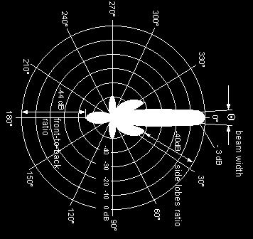
43 Major lobe & minor lobe Major lobe is also called main lobe Defined as the radiation lobe containing the direction of maximum radiation In certain antennas, such as multi-lobed or split beam antennas, there may exist more than one major lobe Minor lobe - A radiation lobe in any direction other than that of the major lobe When its adjacent to the main lobe its called side lobe Side lobe level maximum relative directivity of the highest side lobe with respect to the maximum directivity of the antenna Back lobe refers to a minor lobe that occupies the hemispheres in a direction opposite to that of the major lobe.

44 Radiation pattern lobes
45 Pattern Lobes Pattern lobe is a portion of the radiation pattern with a local maximum Lobes are classified as: major, minor, side lobes, back lobes.
46 Pattern Lobes and Beamwidths
47 Beamwidth - half-power beamwidth and first null beamwidth The width of the main beam or major lobe in terms of angles or radians. Half-power beamwidth (also known as 3dB beamwidth) and first null beamwidth is of interest 3dB beamwidth - In a radiation pattern cut containing the direction of the maximum of a lobe, the angle between the two directions in which the radiation intensity is one-half the maximum value Normally related to the resolution Narrow beam requires large antenna dimensions First-null beamwidth In a radiation pattern cut, the angle between the two nulls adjacent to the main beam
48 Beamwidth Half-power beamwidth (HPBW) is the angle between two vectors from the pattern s origin to the points of the major lobe where the radiation intensity is half its maximum Often used to describe the antenna resolution properties» Important in radar technology, radioastronomy, etc. First-null beamwidth (FNBW) is the angle between two vectors, originating at the pattern s origin and tangent to the main beam at its base.» Often FNBW 2*HPBW
49 Radiation Resistance An antenna s radiation resistance is a measure of its ability to radiate an applied signal into space, or to receive a signal from space. The radiation resistance is not a real (dissipative) resistance, but a measure of the power radiated into free-space for a given input current. The important observation about radiation resistance is that, for a given current into the antenna, as radiation resistance increases, so does the antenna s efficiency.
50 Radiation resistance Radiation resistance R r of an antenna is the hypothetical resistance that would dissipate the same amount of power as the radiated power R r. Lets find the radiation resistance for a short dipole: P rad P ave ds ImL r I ml I ml sin 0 2 sin q r 3 2 q dq sinq dq df First find the total power radiated
51 m rad I L P m r m rad I L R I P L R r Replace and, The power is equivalent to the power dissipated in a fictitious resistance R r by a current I m Thus, the radiation resistance is given by,
52 2.7 Reflection Coefficient The reflection coefficient of a transmitting antenna is defined by: Z A Z 0 Z A Z 0 (dimensionless) can be calculated (as above) or measured. The magnitude of is from 0 to 1. When the transmitting antenna is not macth, i.e., Z A Z 0, there is a loss due to reflection (return loss) of the wave at the antenna terminals. When expressed in db, is always a negative number. Sometimes we use S 11 to represent.
53 2.8 Return Loss The return loss of a transmitting antenna is defined by: return loss 20 log (db) Possible values of return loss are from 0 db Return loss is always a positive number. to db.
54 Standing Wave ratio: The ratio of maximum to minimum voltages along a finite terminated line is called standing wave ratio.
55 2.9 VSWR The voltage standing wave ratio (VSWR) of a transmitting antenna is defined by: VSWR 1 1 (dimensionless) Same as and the return loss, VSWR is also a common parameter used to characterize the matching property of a transmitting antenna. Possible values of VSWR are from 1 to. VSWR=1 perfectly matched. VSWR = completely unmatched.
56 2.10 Impedance Bandwidth or S 11 (db) -10dB f L f C f U Impedance bandwidth Frequency
57 Impedance bandwith f U f L 100% f C Note that when = -10 db, Prob: What will be the VSWR if the reflection coefficient is -10dB
58 Impedance bandwith f U f L 100% f C Note that when = -10 db, VSWR 1 = = Hence the impedance bandwidth can also be specified by the frequency range within which VSWR 2.
59 Prob: Calculate reflection coefficient having SWR of 1.5. Soln:
60 Prob: Calculate reflection coefficient having SWR of 1.5. Soln: return loss or reflection coefficient 20 log (db)
61 Prob: Calculate the radiation resistance of an antenna having wavelength 5 λ = and length 25cm.
62 Prob: Calculate the radiation resistance of an antenna having wavelength 5 λ = and length 25cm.
63 Prob: The maximum power density radiated by a short dipole at a distance of 1 km is 60 (nw/m2). If I0 = 10 A, find the radiation resistance.
64 Prob: The maximum power density radiated by a short dipole at a distance of 1 km is 60 (nw/m 2 ). If I0 = 10 A, find the radiation resistance.
65 Prob: The effective area of an antenna is 9 m 2. What is its directivity in decibels at 3 GHz?
66 Prob: The effective area of an antenna is 9 m 2. What is its directivity in decibels at 3 GHz?
67 Prob: At 100 MHz, the pattern solid angle of an antenna is 1.3 sr. Find (a) the antenna directivity D and (b) its effective area A e.
68 Prob: At 100 MHz, the pattern solid angle of an antenna is 1.3 sr. Find (a) the antenna directivity D and (b) its effective area A e.
69 Problem: The effective area of a parabolic dish antenna is approximately equal to its physical aperture. If the directivity of a dish antenna is 30 db at 10 GHz, what is its effective area? If the frequency is increased to 30 GHz, what will be its new directivity?
70 Problem: The effective area of a parabolic dish antenna is approximately equal to its physical aperture. If the directivity of a dish antenna is 30 db at 10 GHz, what is its effective area? If the frequency is increased to 30 GHz, what will be its new directivity?
71 Problem: Determine the effective area of a half-wave dipole antenna at 100 MHz, if the wire diameter is 2 cm.
72 Problem: Determine the effective area of a half-wave dipole antenna at 100 MHz, if the wire diameter is 2 cm.
73 Terminology Antenna structure or device used to collect or radiate electromagnetic waves Array assembly of antenna elements with dimensions, spacing, and illumination sequency such that the fields of the individual elements combine to produce a maximum intensity in a particular direction and minimum intensities in other directions Beamwidth the angle between the half-power (3-dB) points of the main lobe, when referenced to the peak effective radiated power of the main lobe Directivity the ratio of the radiation intensity in a given direction from the antenna to the radiation intensity averaged over all directions Effective area the functional equivalent area from which an antenna directed toward the source of the received signal gathers or absorbs the energy of an incident electromagnetic wave Efficiency ratio of the total radiated power to the total input power Far field region where wavefront is considered planar Gain ratio of the power at the input of a loss-free isotropic antenna to the power supplied to the input of the given antenna to produce, in a given direction, the same field strength at the same distance Isotropic radiates equally in all directions Main lobe the lobe containing the maximum power Null a zone in which the effective radiated power is at a minimum relative to the maximum effective radiation power of the main lobe Radiation pattern variation of the field intensity of an antenna as an angular function with respect to the axis Radiation resistance resistance that, if inserted in place of the antenna, would consume that same amount of power that is radiated by the antenna 73 Side lobe a lobe in any direction other than the main lobe
74 Friis Transmission Formula A t =Transmitting Effective Area A r =Receiving Effective Area R = Distance between antennas P t = Transmitter power supplied to transmitting antenna P rad = Actually radiated power from transmitting antenna Power density incident upon receiving antenna at a distance R from an isotropic lossless transmitting antenna S iso Pt 4R (9.71) For real transmitting antenna received power density tdtpt G S D S -(9.72) S r t iso t t iso 4R 2 P int = Intercepted power at receiving antenna t = Radiation efficiency of transmitting antenna r = Radiation efficiency of receiving antenna D t = Directivity of transmitting antenna
75 We know effective area of any antenna is defined by 2 D A e (9.64) 4 Using Eq. (9.64), Eq. (9.72) can be expressed in terms of the effective area S r At Pt (9.73) t 2 R 2 A t Power intercepted by receiving antenna = Incident power density P int t At Ar Pt Sr Ar (9.74) 2 2 R Effective area The received power P delivered to the receiver = Intercepted power P rec int radiation efficiency of the receiving antenna P P rec t t A A R 4R (9.75) r t r 2 G G ( ) 2 2 t r This relation is known as the Friis Transmission Formula and the power transfer ratio. Where G and G are gain of transmitting and receiving antenna. t r r P P rec t S r is sometimes called A r
76 Satellite Communication System: Problem 1: A 6 GHz direct-broadcast TV satellite system transmits 100W through a 2 m diameter parabolic dish antenna from a distance of approximately 40,000 km above Earth s surface. Each TV channel occupies a bandwidth of 5 MHz. Due to electromagnetic noise picked up by the antenna as well as noise generated by the receiver electronics, a home TV receiver has a noise level given by P n = KT sys B (W), (9.71) where T sys [measured in kelvins (K)] is a figure of merit called the system noise temperature that characterizes the noise performance of the receiver antenna combination, K is Boltzmann s constant [ (J/K)], and B is the receiver bandwidth in Hz. The signal-to-noise ratio S n (which should not be confused with the power density S is defined as the ratio of Prec to P n : S n = P rec /P n (dimensionless). (9.72) For a receiver with T sys = 580 K, 1) what minimum diameter of a parabolic dish receiving antenna is required for high-qualitytv reception with S n = 40 db? The satellite and ground receiving antennas may be assumed lossless, and their effective areas may be assumed equal to their physical apertures.
77
78 Problem 2: If the operating frequency of the communication system described in Problem 1 is doubled to 12 GHz, what would then be the minimum required diameter of a home receiving TV antenna?
79 Problem 2: If the operating frequency of the communication system described in Example 9-5 is doubled to 12 GHz, what would then be the minimum required diameter of a home receiving TV antenna?
80 Problem 3: A 3-GHz microwave link consists of two identical antennas each with a gain of 30 db. Determine the received power, given that the transmitter output power is 1 kw and the two antennas are 10 km apart.
81 Problem 3: A 3-GHz microwave link consists of two identical antennas each with a gain of 30 db. Determine the received power, given that the transmitter output power is 1 kw and the two antennas are 10 km apart.
82 Problem 4: A 3-GHz line-of-sight microwave communication link consists of two lossless parabolic dish antennas, each 1 m in diameter. If the receive antenna requires 10 nw of receive power for good reception and the distance between the antennas is 40 km, how much power should be transmitted?
83 Problem 4: A 3-GHz line-of-sight microwave communication link consists of two lossless parabolic dish antennas, each 1 m in diameter. If the receive antenna requires 10 nw of receive power for good reception and the distance between the antennas is 40 km, how much power should be transmitted?
84 Problem 5: A half-wave dipole TV broadcast antenna transmits 1 kw at 50MHz. What is the power received by a home television antenna with 3-dB gain if located at a distance of 30 km?

85 Problem 5: A half-wave dipole TV broadcast antenna transmits 1 kwat 50MHz. What is the power received by a home television antenna with 3-dB gain if located at a distance of 30 km?
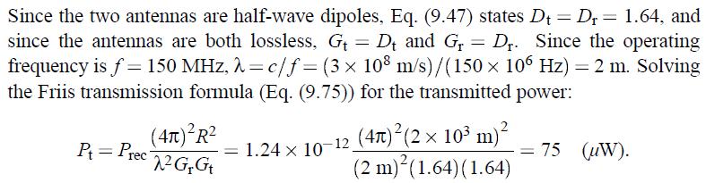
86 Problem 6 A 150-MHz communication link consists of two vertical half-wave dipole antennas separated by 2 km. The antennas are lossless, the signal occupies a bandwidth of 3 MHz, the system noise temperature of the receiver is 600 K, and the desired signalto-noise ratio is 17 db. What transmitter power is required?
87
88
89
90 POLARIZATION The polarization of an antenna is the orientation of the electric field with respect to the Earth's surface and is determined by the physical structure of the antenna and by its orientation. Radio waves from a vertical antenna will usually be vertically polarized. Radio waves from a horizontal antenna are usually horizontally polarized.
91 Direction of Propagation Direction of Propagation


92 Vertically polarized omnidirectional dipole antenna Horizontally polarized directional yagi antenna
93 E y E x E x E x Eectric-field vector Linearly polarized Eectric-field vector Circularly polarized Eectric-field vector Elliptically polarized See animation Polarization of a Plane Wave - 2D View See animation Polarization of a Plane Wave - 3D View
94 Polarization of Plane Waves (a) Linear polarization A plane wave is linearly polarized at a fixed observation point if the tip of the electric-field vector at that point moves along the same straight line at every instant of time. (b) Circular Polarization A plane wave is circularly polarized at a a fixed observation point if the tip of the electric-field vector at that point traces out a circle as a function of time.
95 (c) Circular polarization can be either right-handed or left-handed corresponding to the electric-field vector rotating clockwise (right-handed) or anticlockwise (left-handed). Elliptical Polarization A plane wave is elliptically polarized at a a fixed observation point if the tip of the electric-field vector at that point traces out an ellipse as a function of time. Elliptically polarization can be either right-handed or left-handed corresponding to the electric-field vector rotating clockwise (right-handed) or anti-clockwise (left-handed).
96 Axial Ratio The polarization state of an EM wave can also be indicated by another two parameters: Axial Ratio (AR) and the tilt angle (). AR is a common measure for antenna polarization. It definition is: EE5308 AR OA, OB 1 AR, or 0 db AR db where OA and OB are the major and minor axes of the polarization ellipse, respectively. The tilt angle is the angle subtended by the major axis of the polarization ellipse and the horizontal axis. 29
97 = tilt angle 0 180º
98 For example: AR = 1, 1 < AR < AR =,, circular polarization elliptical polarization linear polarization AR can be measured experimentally! Very often, we use the AR bandwidth and the AR beamwidth to characterize the polarization of an antenna. The AR bandwidth is the frequency bandwidth in which the AR of an antenna changes less than 3 db from its minimum value. The AR beamwidth is the angle span over which the AR of an antenna changes less than 3 db from its mimumum value.
99 3 db AR beamwidth Radiation pattern with a rotating linear source q AR at q in db scale Test antenna (receiving) Fast-rotating dipole antenna (transmitting)
100 Axial ratio (db) 3dB AR bandwidth Freq uency
101 Thank You
102
103 Friis transmission formula At a fixed distance R from the transmitting antenna, the power intercepted by the receiving antenna with effective aperture A r is P 4 R t Pi Sr Ar 2 where S r is the received power density (W/m 2 ), and G t is the peak gain of the transmitting antenna. G t A r
Chapter 2. Fundamental Properties of Antennas. ECE 5318/6352 Antenna Engineering Dr. Stuart Long
 Chapter Fundamental Properties of Antennas ECE 5318/635 Antenna Engineering Dr. Stuart Long 1 IEEE Standards Definition of Terms for Antennas IEEE Standard 145-1983 IEEE Transactions on Antennas and Propagation
Antenna Fundamentals Basics antenna theory and concepts
 Antenna Fundamentals Basics antenna theory and concepts M. Haridim Brno University of Technology, Brno February 2017 1 Topics What is antenna Antenna types Antenna parameters: radiation pattern, directivity,
S=E H ANTENNA RADIATION
 ANTENNA RADIATION Antennas radiate spherical waves that propagate in the radial direction for a coordinate system centered on the antenna. At large distances, spherical waves can be approx imated by plane
UNIT Explain the radiation from two-wire. Ans: Radiation from Two wire
 UNIT 1 1. Explain the radiation from two-wire. Radiation from Two wire Figure1.1.1 shows a voltage source connected two-wire transmission line which is further connected to an antenna. An electric field
EMG4066:Antennas and Propagation Exp 1:ANTENNAS MMU:FOE. To study the radiation pattern characteristics of various types of antennas.
 OBJECTIVES To study the radiation pattern characteristics of various types of antennas. APPARATUS Microwave Source Rotating Antenna Platform Measurement Interface Transmitting Horn Antenna Dipole and Yagi
ANTENNAS AND WAVE PROPAGATION EC602
 ANTENNAS AND WAVE PROPAGATION EC602 B.Tech Electronics & Communication Engineering, Semester VI INSTITUTE OF TECHNOLOGY NIRMA UNIVERSITY 1 Lesson Planning (L-3,P-2,C-4) Chapter No. Name Hours 1. Basic
Antenna & Propagation. Antenna Parameters
 For updated version, please click on http://ocw.ump.edu.my Antenna & Propagation Antenna Parameters by Nor Hadzfizah Binti Mohd Radi Faculty of Electric & Electronics Engineering hadzfizah@ump.edu.my Chapter
ANTENNA INTRODUCTION / BASICS
 ANTENNA INTRODUCTION / BASICS RULES OF THUMB: 1. The Gain of an antenna with losses is given by: 2. Gain of rectangular X-Band Aperture G = 1.4 LW L = length of aperture in cm Where: W = width of aperture
Topic 3. Fundamental Parameters of Antennas. Tamer Abuelfadl
 Topic 3 Fundamental Parameters of Antennas Tamer Abuelfadl Electronics and Electrical Communications Department Faculty of Engineering Cairo University Tamer Abuelfadl (EEC, Cairo University) Topic 3 ELC
An Introduction to Antennas
 May 11, 010 An Introduction to Antennas 1 Outline Antenna definition Main parameters of an antenna Types of antennas Antenna radiation (oynting vector) Radiation pattern Far-field distance, directivity,
Dr. John S. Seybold. November 9, IEEE Melbourne COM/SP AP/MTT Chapters
 Antennas Dr. John S. Seybold November 9, 004 IEEE Melbourne COM/SP AP/MTT Chapters Introduction The antenna is the air interface of a communication system An antenna is an electrical conductor or system
EC ANTENNA AND WAVE PROPAGATION
 EC6602 - ANTENNA AND WAVE PROPAGATION FUNDAMENTALS PART-B QUESTION BANK UNIT 1 1. Define the following parameters w.r.t antenna: i. Radiation resistance. ii. Beam area. iii. Radiation intensity. iv. Directivity.
RADAR Antennas R A D A R R A D A R S Y S T E M S S Y S T E M S. Lecture DR Sanjeev Kumar Mishra. 2 max
 Y T E M Y T E M anjeev Kumar Mishra Lecture 17-20 ntennas i p r t t ne L L L N kt BF PG 1 0 3 2 max 4 ) / ( 4 2 Y T E M ntenna: n antenna is an electromagnetic radiator, a sensor, a transducer and an impedance
Notes 21 Introduction to Antennas
 ECE 3317 Applied Electromagnetic Waves Prof. David R. Jackson Fall 018 Notes 1 Introduction to Antennas 1 Introduction to Antennas Antennas An antenna is a device that is used to transmit and/or receive
Antennas 1. Antennas
 Antennas Antennas 1! Grading policy. " Weekly Homework 40%. " Midterm Exam 30%. " Project 30%.! Office hour: 3:10 ~ 4:00 pm, Monday.! Textbook: Warren L. Stutzman and Gary A. Thiele, Antenna Theory and
KULLIYYAH OF ENGINEERING
 KULLIYYAH OF ENGINEERING DEPARTMENT OF ELECTRICAL & COMPUTER ENGINEERING ANTENNA AND WAVE PROPAGATION LABORATORY (ECE 4103) EXPERIMENT NO 3 RADIATION PATTERN AND GAIN CHARACTERISTICS OF THE DISH (PARABOLIC)
ANTENNA INTRODUCTION / BASICS
 Rules of Thumb: 1. The Gain of an antenna with losses is given by: G 0A 8 Where 0 ' Efficiency A ' Physical aperture area 8 ' wavelength ANTENNA INTRODUCTION / BASICS another is:. Gain of rectangular X-Band
ANTENNA THEORY. Analysis and Design. CONSTANTINE A. BALANIS Arizona State University. JOHN WILEY & SONS New York Chichester Brisbane Toronto Singapore
 ANTENNA THEORY Analysis and Design CONSTANTINE A. BALANIS Arizona State University JOHN WILEY & SONS New York Chichester Brisbane Toronto Singapore Contents Preface xv Chapter 1 Antennas 1 1.1 Introduction
Antenna Fundamentals. Microwave Engineering EE 172. Dr. Ray Kwok
 Antenna Fundamentals Microwave Engineering EE 172 Dr. Ray Kwok Reference Antenna Theory and Design Warran Stutzman, Gary Thiele, Wiley & Sons (1981) Microstrip Antennas Bahl & Bhartia, Artech House (1980)
Antenna Fundamentals
 HTEL 104 Antenna Fundamentals The antenna is the essential link between free space and the transmitter or receiver. As such, it plays an essential part in determining the characteristics of the complete
Travelling Wave, Broadband, and Frequency Independent Antennas. EE-4382/ Antenna Engineering
 Travelling Wave, Broadband, and Frequency Independent Antennas EE-4382/5306 - Antenna Engineering Outline Traveling Wave Antennas Introduction Traveling Wave Antennas: Long Wire, V Antenna, Rhombic Antenna
Antenna Parameters. Ranga Rodrigo. University of Moratuwa. December 15, 2008
 Antenna Parameters Ranga Rodrigo University of Moratuwa December 15, 2008 Ranga Rodrigo (University of Moratuwa) Antenna Parameters December 15, 2008 1 / 47 Summary of Last Week s Lecture 90 o Radiation
ELEC 425 Interference Control in Electronics Lecture 7(a) Introduction to Antennas: Terminology
 Introduction to Antennas: Terminology") Dr. Gregory J. Mazzaro Fall 017 ELEC 45 Interference Control in Electronics Lecture 7(a) Introduction to Antennas: Terminology Chapter 9 THE CITADEL, THE MILITARY COLLEGE OF SOUTH CAROLINA 171 Moultrie
Dr. Gregory J. Mazzaro Fall 017 ELEC 45 Interference Control in Electronics Lecture 7(a) Introduction to Antennas: Terminology Chapter 9 THE CITADEL, THE MILITARY COLLEGE OF SOUTH CAROLINA 171 Moultrie
( ) 2 ( ) 3 ( ) + 1. cos! t " R / v p 1 ) H =! ˆ" I #l ' $ 2 ' 2 (18.20) * + ! ˆ& "I #l ' $ 2 ' , ( βr << 1. "l ' E! ˆR I 0"l ' cos& + ˆ& 0
 2 ( ) 3 ( ) + 1. cos! t R / v p 1 ) H =! ˆ I #l ' $ 2 ' 2 (18.20) * + ! ˆ& I #l ' $ 2 ' , ( βr << 1. l ' E! ˆR I 0l ' cos& + ˆ& 0") Summary Chapter 8. This last chapter treats the problem of antennas and radiation from antennas. We start with the elemental electric dipole and introduce the idea of retardation of potentials and fields
Summary Chapter 8. This last chapter treats the problem of antennas and radiation from antennas. We start with the elemental electric dipole and introduce the idea of retardation of potentials and fields
Traveling Wave Antennas
 Traveling Wave Antennas Antennas with open-ended wires where the current must go to zero (dipoles, monopoles, etc.) can be characterized as standing wave antennas or resonant antennas. The current on these
Antennas Prof. Girish Kumar Department of Electrical Engineering India Institute of Technology, Bombay. Module - 1 Lecture - 1 Antennas Introduction-I
 Antennas Prof. Girish Kumar Department of Electrical Engineering India Institute of Technology, Bombay Module - 1 Lecture - 1 Antennas Introduction-I Hello everyone. Welcome to the exciting world of antennas.
HHTEHHH THEORY ANALYSIS AND DESIGN. CONSTANTINE A. BALANIS Arizona State University
 HHTEHHH THEORY ANALYSIS AND DESIGN CONSTANTINE A. BALANIS Arizona State University JOHN WILEY & SONS, INC. New York Chichester Brisbane Toronto Singapore Contents Preface V CHAPTER 1 ANTENNAS 1.1 Introduction
BHARATHIDASAN ENGINEERING COLLEGE NATTARAMPALLI Frequently Asked Questions (FAQ) Unit 1
 Unit 1") BHARATHIDASAN ENGINEERING COLLEGE NATTARAMPALLI 635854 Frequently Asked Questions (FAQ) Unit 1 Degree / Branch : B.E / ECE Sem / Year : 3 rd / 6 th Sub Name : Antennas & Wave Propagation Sub Code : EC6602
BHARATHIDASAN ENGINEERING COLLEGE NATTARAMPALLI 635854 Frequently Asked Questions (FAQ) Unit 1 Degree / Branch : B.E / ECE Sem / Year : 3 rd / 6 th Sub Name : Antennas & Wave Propagation Sub Code : EC6602
Half-Wave Dipole. Radiation Resistance. Antenna Efficiency
 Antennas Simple Antennas Isotropic radiator is the simplest antenna mathematically Radiates all the power supplied to it, equally in all directions Theoretical only, can t be built Useful as a reference:
SI TECHNICAL 2018 UNIT IV QUESTION BANK
 SI TECHNICAL 2018 UNIT IV QUESTION BANK 1. In what range of frequencies are most omnidirectional horizontally polarized antennas used? A. VHF, UHF B. VLF, LF C. SH, EHF D. MF, HF 2. If the current ratios
CHAPTER 5 THEORY AND TYPES OF ANTENNAS. 5.1 Introduction
 CHAPTER 5 THEORY AND TYPES OF ANTENNAS 5.1 Introduction Antenna is an integral part of wireless communication systems, considered as an interface between transmission line and free space [16]. Antenna
Antennas and Propagation. Chapter 4: Antenna Types
 Antennas and Propagation : Antenna Types 4.4 Aperture Antennas High microwave frequencies Thin wires and dielectrics cause loss Coaxial lines: may have 10dB per meter Waveguides often used instead Aperture
Exercise 1-3. Radar Antennas EXERCISE OBJECTIVE DISCUSSION OUTLINE DISCUSSION OF FUNDAMENTALS. Antenna types
 Exercise 1-3 Radar Antennas EXERCISE OBJECTIVE When you have completed this exercise, you will be familiar with the role of the antenna in a radar system. You will also be familiar with the intrinsic characteristics
"Natural" Antennas. Mr. Robert Marcus, PE, NCE Dr. Bruce C. Gabrielson, NCE. Security Engineering Services, Inc. PO Box 550 Chesapeake Beach, MD 20732
 Published and presented: AFCEA TEMPEST Training Course, Burke, VA, 1992 Introduction "Natural" Antennas Mr. Robert Marcus, PE, NCE Dr. Bruce C. Gabrielson, NCE Security Engineering Services, Inc. PO Box
Final Examination. 22 April 2013, 9:30 12:00. Examiner: Prof. Sean V. Hum. All non-programmable electronic calculators are allowed.
 UNIVERSITY OF TORONTO FACULTY OF APPLIED SCIENCE AND ENGINEERING The Edward S. Rogers Sr. Department of Electrical and Computer Engineering ECE 422H1S RADIO AND MICROWAVE WIRELESS SYSTEMS Final Examination
6 Radio and RF. 6.1 Introduction. Wavelength (m) Frequency (Hz) Unit 6: RF and Antennas 1. Radio waves. X-rays. Microwaves. Light
 Frequency (Hz) Unit 6: RF and Antennas 1. Radio waves. X-rays. Microwaves. Light") 6 Radio and RF Ref: http://www.asecuritysite.com/wireless/wireless06 6.1 Introduction The electromagnetic (EM) spectrum contains a wide range of electromagnetic waves, from radio waves up to X-rays (as
6 Radio and RF Ref: http://www.asecuritysite.com/wireless/wireless06 6.1 Introduction The electromagnetic (EM) spectrum contains a wide range of electromagnetic waves, from radio waves up to X-rays (as
S.R.M. Institute of Science & Technology Deemed University School of Electronics & Communication Engineering
 S.R.M. Institute of Science & Technology Deemed University School of Electronics & Communication Engineering Question Bank Subject Code : EC401 Subject Name : Antennas and Wave Propagation Year & Sem :
It is clear in Figures a and b that in some very specific directions there are zeros, or nulls, in the pattern indicating no radiation.
 Unit 2 - Point Sources and Arrays Radiation pattern: The radiation pattern of antenna is a representation (pictorial or mathematical) of the distribution of the power out-flowing (radiated) from the antenna
Continuous Arrays Page 1. Continuous Arrays. 1 One-dimensional Continuous Arrays. Figure 1: Continuous array N 1 AF = I m e jkz cos θ (1) m=0
 m=0") Continuous Arrays Page 1 Continuous Arrays 1 One-dimensional Continuous Arrays Consider the 2-element array we studied earlier where each element is driven by the same signal (a uniform excited array),
Continuous Arrays Page 1 Continuous Arrays 1 One-dimensional Continuous Arrays Consider the 2-element array we studied earlier where each element is driven by the same signal (a uniform excited array),
Chapter 4 The RF Link
 Chapter 4 The RF Link The fundamental elements of the communications satellite Radio Frequency (RF) or free space link are introduced. Basic transmission parameters, such as Antenna gain, Beamwidth, Free-space
Newsletter 4.4. Antenna Magus version 4.4 released! Array synthesis reflective ground plane addition. July 2013
 Newsletter 4.4 July 2013 Antenna Magus version 4.4 released! We are pleased to announce the new release of Antenna Magus Version 4.4. This release sees the addition of 5 new antennas: Horn-fed truncated
ANTENNAS & WAVE PROPAGATION
 ANTENNAS & WAVE PROPAGATION R13 III B Tech I SEMESTER 1 III Year I SEMESTER T P C 3+1 0 3 ANTENNAS AND WAVE PROPAGATION OBJECTIVES UNIT I ANTENNA FUNDAMENTALS: Introduction, Radiation Mechanism single
The Basics of Patch Antennas, Updated
 The Basics of Patch Antennas, Updated By D. Orban and G.J.K. Moernaut, Orban Microwave Products www.orbanmicrowave.com Introduction This article introduces the basic concepts of patch antennas. We use
Antenna Engineering Lecture 3: Basic Antenna Parameters
 Antenna Engineering Lecture 3: Basic Antenna Parameters ELC 405a Fall 2011 Department of Electronics and Communications Engineering Faculty of Engineering Cairo University 2 Outline 1 Radiation Pattern
Practical Antennas and. Tuesday, March 4, 14
 Practical Antennas and Transmission Lines Goals Antennas are the interface between guided waves (from a cable) and unguided waves (in space). To understand the various properties of antennas, so as to
Unit 4. Antenna Theory
 Unit 4. Antenna Theory A person, who needs to convey a thought, an idea or a doubt, can do so by voice communication. The following illustration shows two individuals communicating with each other. Here,
INSTITUTE OF AERONAUTICAL ENGINEERING Dundigal, Hyderabad ELECTRONICS AND COMMUNIACTION ENGINEERING QUESTION BANK
 INSTITUTE OF AERONAUTICAL ENGINEERING Dundigal, Hyderabad - 500 04 ELECTRONICS AND COMMUNIACTION ENGINEERING QUESTION BANK Course Name : Antennas and Wave Propagation (AWP) Course Code : A50418 Class :
Antennas & wave Propagation ASSIGNMENT-I
 Shri Vishnu Engineering College for Women :: Bhimavaram Department of Electronics & Communication Engineering Antennas & wave Propagation 1. Define the terms: i. Antenna Aperture ii. Beam Width iii. Aperture
Rec. ITU-R F RECOMMENDATION ITU-R F *
 Rec. ITU-R F.162-3 1 RECOMMENDATION ITU-R F.162-3 * Rec. ITU-R F.162-3 USE OF DIRECTIONAL TRANSMITTING ANTENNAS IN THE FIXED SERVICE OPERATING IN BANDS BELOW ABOUT 30 MHz (Question 150/9) (1953-1956-1966-1970-1992)
The magnetic surface current density is defined in terms of the electric field at an aperture as follows: 2E n (6.1)
") Chapter 6. Aperture antennas Antennas where radiation occurs from an open aperture are called aperture antennas. xamples include slot antennas, open-ended waveguides, rectangular and circular horn antennas,
Chapter 6. Aperture antennas Antennas where radiation occurs from an open aperture are called aperture antennas. xamples include slot antennas, open-ended waveguides, rectangular and circular horn antennas,
Chapter 3 Solution to Problems
 Chapter 3 Solution to Problems 1. The telemetry system of a geostationary communications satellite samples 100 sensors on the spacecraft in sequence. Each sample is transmitted to earth as an eight-bit
CHAPTER 2 MICROSTRIP REFLECTARRAY ANTENNA AND PERFORMANCE EVALUATION
 43 CHAPTER 2 MICROSTRIP REFLECTARRAY ANTENNA AND PERFORMANCE EVALUATION 2.1 INTRODUCTION This work begins with design of reflectarrays with conventional patches as unit cells for operation at Ku Band in
ELEC4604. RF Electronics. Experiment 1
 ELEC464 RF Electronics Experiment ANTENNA RADATO N PATTERNS. ntroduction The performance of RF communication systems depend critically on the radiation characteristics of the antennae it employs. These
ANTENNAS 101 An Introduction to Antennas for Ham Radio. Lee KD4RE
 ANTENNAS 101 An Introduction to Antennas for Ham Radio Lee KD4RE Prepared for Presentation at the Vienna Wireless Society, 13 January 2017 So What is an Antenna Anyway? We are all familiar with wire antennas
Aperture Antennas. Reflectors, horns. High Gain Nearly real input impedance. Huygens Principle
 Antennas 97 Aperture Antennas Reflectors, horns. High Gain Nearly real input impedance Huygens Principle Each point of a wave front is a secondary source of spherical waves. 97 Antennas 98 Equivalence
ELEG 648 Radiation/Antennas I. Mark Mirotznik, Ph.D. Associate Professor The University of Delaware
 ELEG 648 Radiation/Antennas I Mark Mirotznik Ph.D. Associate Professor The University of Delaware A jk rr ' e ' r J r dv ' 4 r r ' F If we have magnetic sources jk rr ' e ' r M r dv ' 4 r r ' Field
LECTURE 4: Fundamental Antenna Parameters 1. Radiation Pattern Note:
 LECTURE 4: Fundamental Antenna Parameters (Radiation pattern. Pattern beamwidths. Radiation intensity. Directivity. Gain. Antenna efficiency and radiation efficiency. Frequency bandwidth. Input impedance
J/K). Nikolova
. Nikolova") Lecture 7: ntenna Noise Temperature and System Signal-to-Noise Ratio (Noise temperature. ntenna noise temperature. System noise temperature. Minimum detectable temperature. System signal-to-noise ratio.)
Lecture 7: ntenna Noise Temperature and System Signal-to-Noise Ratio (Noise temperature. ntenna noise temperature. System noise temperature. Minimum detectable temperature. System signal-to-noise ratio.)
Chapter 6 Antenna Basics. Dipoles, Ground-planes, and Wires Directional Antennas Feed Lines
 Chapter 6 Antenna Basics Dipoles, Ground-planes, and Wires Directional Antennas Feed Lines Some General Rules Bigger is better. (Most of the time) Higher is better. (Most of the time) Lower SWR is better.
24. Antennas. What is an antenna. Types of antennas. Reciprocity
 4. Antennas What is an antenna Types of antennas Reciprocity Hertzian dipole near field far field: radiation zone radiation resistance radiation efficiency Antennas convert currents to waves An antenna
Newsletter 2.0. Antenna Magus version 2.0 released! New Array synthesis tool. April 2010
 Newsletter 2.0 April 2010 Antenna Magus version 2.0 released! We are very proud to announce the second major release of Antenna Magus, Version 2.0. Looking back over the past 11 months since release 1.0
Design of Linearly Polarized Rectangular Microstrip Patch Antenna for GPS Applications at MHz
 Design of Linearly Polarized Rectangular Microstrip Patch Antenna for GPS Applications at 1575.4MHz P. S. S. Pavan Ganesh Associate Professor, Sreyas Institute of Engineering and Technology, Hyderabad
Resonant Antennas: Wires and Patches
 Resonant Antennas: Wires and Patches Dipole Antennas Antenna 48 Current distribution approximation Un-normalized pattern: and Antenna 49 Radiating power: For half-wave dipole and,, or at exact resonance.
A LABORATORY COURSE ON ANTENNA MEASUREMENT
 A LABORATORY COURSE ON ANTENNA MEASUREMENT Samuel Parker Raytheon Systems Company, 2000 East Imperial Highway RE/R02/V509, El Segundo, CA 90245 Dean Arakaki Electrical Engineering Department, California
EEM.Ant. Antennas and Propagation
 EEM.ant/0304/08pg/Req: None 1/8 UNIVERSITY OF SURREY Department of Electronic Engineering MSc EXAMINATION EEM.Ant Antennas and Propagation Duration: 2 Hours Spring 2003/04 READ THESE INSTRUCTIONS Answer
THE ELECTROMAGNETIC FIELD THEORY. Dr. A. Bhattacharya
 1 THE ELECTROMAGNETIC FIELD THEORY Dr. A. Bhattacharya The Underlying EM Fields The development of radar as an imaging modality has been based on power and power density It is important to understand some
Introduction to Radar Systems. Radar Antennas. MIT Lincoln Laboratory. Radar Antennas - 1 PRH 6/18/02
 Introduction to Radar Systems Radar Antennas Radar Antennas - 1 Disclaimer of Endorsement and Liability The video courseware and accompanying viewgraphs presented on this server were prepared as an account
(i) Determine the admittance parameters of the network of Fig 1 (f) and draw its - equivalent circuit.
 Determine the admittance parameters of the network of Fig 1 (f) and draw its - equivalent circuit.") I.E.S-(Conv.)-1995 ELECTRONICS AND TELECOMMUNICATION ENGINEERING PAPER - I Some useful data: Electron charge: 1.6 10 19 Coulomb Free space permeability: 4 10 7 H/m Free space permittivity: 8.85 pf/m Velocity
I.E.S-(Conv.)-1995 ELECTRONICS AND TELECOMMUNICATION ENGINEERING PAPER - I Some useful data: Electron charge: 1.6 10 19 Coulomb Free space permeability: 4 10 7 H/m Free space permittivity: 8.85 pf/m Velocity
25. Antennas II. Radiation patterns. Beyond the Hertzian dipole - superposition. Directivity and antenna gain. More complicated antennas
 25. Antennas II Radiation patterns Beyond the Hertzian dipole - superposition Directivity and antenna gain More complicated antennas Impedance matching Reminder: Hertzian dipole The Hertzian dipole is
Radiation and Antennas
 Chapter 9 Radiation and Antennas. Basic Formulations 2. Hertzian Dipole Antenna 3. Linear Antennas An antenna is a device to transmit or receive electromagnetic power more efficiently with a more directive
Fields and Waves I. Lecture 26. Intro to Antennas & Propagation K. A. Connor
 Fields and Waves I Lecture 26 Intro to Antennas & Propagation K. A. Connor Electrical, Computer, and Systems Engineering Department Rensselaer Polytechnic Institute, Troy, NY These Slides Were Prepared
Dhayalini Ramamoorthy. January Master s Thesis in Electronics
 FACULTY OF ENGINEERING AND SUSTAINABLE DEVELOPMENT. Impact of Mutual Coupling among Antenna Arrays on the Performance of the Multipath Simulator System Dhayalini Ramamoorthy January 2014 Master s Thesis
ANTENNAS. I will mostly be talking about transmission. Keep in mind though, whatever is said about transmission is true of reception.
 Reading 37 Ron Bertrand VK2DQ http://www.radioelectronicschool.com ANTENNAS The purpose of an antenna is to receive and/or transmit electromagnetic radiation. When the antenna is not connected directly
UNIT-3. Ans: Arrays of two point sources with equal amplitude and opposite phase:
 `` UNIT-3 1. Derive the field components and draw the field pattern for two point source with spacing of λ/2 and fed with current of equal n magnitude but out of phase by 180 0? Ans: Arrays of two point
You will need the following pieces of equipment to complete this experiment: Wilkinson power divider (3-port board with oval-shaped trace on it)
") UNIVERSITY OF TORONTO FACULTY OF APPLIED SCIENCE AND ENGINEERING The Edward S. Rogers Sr. Department of Electrical and Computer Engineering ECE422H1S: RADIO AND MICROWAVE WIRELESS SYSTEMS EXPERIMENT 1:
UNIVERSITY OF TORONTO FACULTY OF APPLIED SCIENCE AND ENGINEERING The Edward S. Rogers Sr. Department of Electrical and Computer Engineering ECE422H1S: RADIO AND MICROWAVE WIRELESS SYSTEMS EXPERIMENT 1:
UNIT Write short notes on travelling wave antenna? Ans: Travelling Wave Antenna
 UNIT 4 1. Write short notes on travelling wave antenna? Travelling Wave Antenna Travelling wave or non-resonant or aperiodic antennas are those antennas in which there is no reflected wave i.e., standing
KINGS COLLEGE OF ENGINEERING DEPARTMENT OF ELECTRONICS AND COMMUNICATION ENGINEERING QUESTION BANK
 KINGS COLLEGE OF ENGINEERING DEPARTMENT OF ELECTRONICS AND COMMUNICATION ENGINEERING QUESTION BANK SUB.NAME : ANTENNAS & WAVE PROPAGATION SUB CODE : EC 1352 YEAR : III SEMESTER : VI UNIT I: ANTENNA FUNDAMENTALS
Theory of Helix Antenna
 Theory of Helix Antenna Tariq Rahim School of Electronic and information, NWPU, Xian china Review on Helix Antenna 1 Introduction The helical antenna is a hybrid of two simple radiating elements, the dipole
Antenna Trainer EAN. Technical Teaching Equipment INTRODUCTION
 Antenna Trainer EAN Technical Teaching Equipment Products Products range Units 3.-Communications INTRODUCTION Antennas are the main element of aerial communications. They are the transition between a transmission
CHAPTER 5 PRINTED FLARED DIPOLE ANTENNA
 CHAPTER 5 PRINTED FLARED DIPOLE ANTENNA 5.1 INTRODUCTION This chapter deals with the design of L-band printed dipole antenna (operating frequency of 1060 MHz). A study is carried out to obtain 40 % impedance
The concept of transmission loss for radio links
 Recommendation ITU-R P.341-6 (09/2016) The concept of transmission loss for radio links P Series Radiowave propagation ii Rec. ITU-R P.341-6 Foreword The role of the Radiocommunication Sector is to ensure
I J E E Volume 5 Number 1 January-June 2013 pp
 I J E E Volume 5 Number 1 January-June 2013 pp. 21-25 Serials Publications, ISSN : 0973-7383 Various Antennas and Its Applications in Wireless Domain: A Review Paper P.A. Ambresh 1, P.M. Hadalgi 2 and
KINGS COLLEGE OF ENGINEERING. DEPARTMENT OF ELECTRONICS AND COMMUNICATION ENGINEERING Academic Year (Even Sem) QUESTION BANK (AUTT-R2008)
 QUESTION BANK (AUTT-R2008)") KINGS COLLEGE OF ENGINEERING DEPARTMENT OF ELECTRONICS AND COMMUNICATION ENGINEERING Academic Year 2012-2013(Even Sem) QUESTION BANK (AUTT-R2008) SUBJECT CODE /NAME: EC 1352 / ANTENNEA AND WAVE PROPAGATION
KINGS COLLEGE OF ENGINEERING DEPARTMENT OF ELECTRONICS AND COMMUNICATION ENGINEERING Academic Year 2012-2013(Even Sem) QUESTION BANK (AUTT-R2008) SUBJECT CODE /NAME: EC 1352 / ANTENNEA AND WAVE PROPAGATION
OSCILLATORS AND MIXERS RF Oscillators 605. Crystal Oscillators Microwave Oscillators 613
 xvi 13 Contents OSCILLATORS AND MIXERS 604 13.1 RF Oscillators 605 General Analysis 606 Oscillators Using a Common Emitter BJT 607 Oscillators Using a Common Gate FET 609 Practical Considerations 610 Crystal
MICROWAVE ENGINEERING MCQs
 MICROWAVE ENGINEERING MCQs 1) If an antenna draws 12 A current and radiates 4 kw, then what will be its radiation resistance? a. 22.22 ohm b. 27.77 ohm c. 33.33 ohm d. 39.77 ohm 2) Which mode of radiation
Fundamentals of Antennas. Prof. Ely Levine
 Fundamentals of Antennas Prof. Ely Levine levineel@zahav.net.il 1 Chapter 3 Wire Antennas 2 Types of Antennas 3 Isotropic Antenna Isotropic radiator is the simplest antenna mathematically Radiates all
ANTENNA TUTORIAL 1. INTRODUCTION 2. CLASSIFICATION OF ANTENNAS
 ANTENNA TUTORIAL Phumzile Malindi, Department of Electrical Engineering, Walter Sisulu University, 19 Manchester Road, Chiselhurst, EAST LONDON, 501, South Africa pmalindi@webmail.co.za 1. INTRODUCTION
Introduction to Antennas
 Introduction to Antennas By John S. Seybold, Ph.D., P.E. This short course has been adapted from the text Introduction to RF Propagation, by John S. Seybold, Wiley 2005. Most of the material herein in
Impedance and Loop Antennas
 Impedance and Loop Antennas Ranga Rodrigo University of Moratuwa January 4, 2009 Ranga Rodrigo (University of Moratuwa) Impedance and Loop Antennas January 4, 2009 1 / 41 Gain Summary of Last Week s Lecture
CHAPTER 8 ANTENNAS 1
 CHAPTER 8 ANTENNAS 1 2 Antennas A good antenna works A bad antenna is a waste of time & money Antenna systems can be very inexpensive and simple They can also be very expensive 3 Antenna Considerations
1 Propagation in free space and the aperture antenna
 1 Propagation in free space and the aperture antenna This chapter introduces the basic concepts of radio signals travelling from one antenna to another. The aperture antenna is used initially to illustrate
DEPARTMENT OF ELECTRONICS & COMMUNICATION ENGINEERING SUBJECT NAME:
 Chendu College of Engineering & Technology (Approved by AICTE, New Delhi and Affiliated to Anna University) Zamin Endathur, Madurantakam, Kancheepuram, District 603311. DEPARTMENT OF ELECTRONICS & COMMUNICATION
August, Antennas 101: A Course in RF Basics
 August, 2012 Antennas 101: A Course in RF Basics Antenna Basics Agenda: In today s training, we will go over a brief summary of the following topics at a basic level: Electromagnetic Waves Frequency and
The Benefits of BEC s Antenna Design
 The Benefits of BEC s Antenna Design Overview The explosive growth of wireless data communications is fast emerging with high peak data rates, which require superior antenna performance and design to support
Range Considerations for RF Networks
 TI Technology Days 2010 Range Considerations for RF Networks Richard Wallace Abstract The antenna can be one of the most daunting components of wireless designs. Most information available relates to large
Diseño de antenas de ranura de doble banda en tecnología inverted microstrip gap waveguide de bajo coste
 Universidad Carlos III de Madrid Repositorio institucional e-archivo Trabajos académicos http://e-archivo.uc3m.es Trabajos Fin de Grado Escuela Politécnica Superior 2015 Diseño de antenas de ranura de
YAGI-UDA DESIGN OF U.H.F BAND AERIAL TO SUIT LOCAL TV STATIONS
 YAGI-UDA DESIGN OF U.H.F BAND AERIAL TO SUIT LOCAL TV STATIONS PROJECT INDEX: PRJ 079 Presented By: GITAU SIMON WAWERU F17/8261/2004 Supervisor: Mr. S.L OGABA Examiner: Mr. OMBURA Objective The main objective
We are IntechOpen, the world s leading publisher of Open Access books Built by scientists, for scientists. International authors and editors
 We are IntechOpen, the world s leading publisher of Open Access books Built by scientists, for scientists 3,900 116,000 120M Open access books available International authors and editors Downloads Our
Antenna & Wave Propagation (Subject Code: 7EC1)
") COMPUCOM INSTITUTE OF TECHNOLOGY & MANAGEMENT, JAIPUR (DEPARTMENT OF ELECTRONICS & COMMUNICATION) Notes Antenna & Wave Propagation (Subject Code: 7EC1) Prepared By: Raj Kumar Jain Class: B. Tech. IV Year,
COMPUCOM INSTITUTE OF TECHNOLOGY & MANAGEMENT, JAIPUR (DEPARTMENT OF ELECTRONICS & COMMUNICATION) Notes Antenna & Wave Propagation (Subject Code: 7EC1) Prepared By: Raj Kumar Jain Class: B. Tech. IV Year,
Yagi-Uda (Beam) Antenna
 Antenna") Yagi-Uda (Beam) Antenna Gary A. Thiele KD8ZWS (Ex W8RBW) Co-author of Antenna Theory & Design John Wiley & Sons, 1981, 1998, 2013 Yagi-Uda (Beam) Antennas Outline Preliminary Remarks Part I Brief history
Yagi-Uda (Beam) Antenna Gary A. Thiele KD8ZWS (Ex W8RBW) Co-author of Antenna Theory & Design John Wiley & Sons, 1981, 1998, 2013 Yagi-Uda (Beam) Antennas Outline Preliminary Remarks Part I Brief history