Antenna Theory EELE 5445
|
|
|
- Geoffrey Gardner
- 5 years ago
- Views:
Transcription


1 Antenna Theory EELE 5445 Lecture 6: Dipole Antenna Dr. Mohamed Ouda Electrical Engineering Department Islamic University of Gaza 2013
2 The dipole and the monopole The dipole and the monopole are arguably the two most widely used antennas across the UHF, VHF and lower-microwave bands. Arrays of dipoles are commonly used as base-station antennas in land-mobile systems. The monopole and its variations are perhaps the most common antennas for portable equipment, such as cellular telephones, cordless telephones, automobiles, trains, etc. It has attractive features such as simple construction, sufficiently broadband characteristics for voice communication, small dimensions at high frequencies. An alternative to the monopole antenna for hand-held units is the loop antenna, the microstrip patch antenna, the spiral antennas, inverted-l and inverted-f antennas, and others. 2
3 Small dipole Assuming occur is, The maximum phase error βr in that can at θ=0 Reminder: A maximum total phase error of π/8 is acceptable since it does not affect substantially the integral solution for the vector potential A. The assumption is made here for both, the amplitude and the phase factors in the kernel of the VP integral. 3
4 The current is a triangular function of : 'z 4
5 The solution for A is simple when we assume that Note that A is exactly one-half of the result obtained for A of an infinitesimal dipole of the same length, if I m were the current uniformly distributed along the dipole. This is expected because we made the same approximation for R, as in the case of the infinitesimal dipole with a constant current distribution, and we integrated a triangular function along l, whose average is Therefore, we need not repeat all the calculations of the field components, power and antenna parameters. We make use of our knowledge of the infinitesimal dipole field. 5
6 The far-field components of the small dipole are simply half those of the infinitesimal dipole: The normalized field pattern is the same as that of the infinitesimal dipole: 6
7 7
8 The beam solid angle: The directivity As expected, the directivity, the beam solid angle as well as the effective aperture are the same as those of the infinitesimal dipole because the normalized patterns of both dipoles are the same. 8
9 The radiated power is four times less than that of an infinitesimal dipole of the same length and current because the far fields are twice smaller in magnitude: I 0 = I m As a result, the radiation resistance is also four times smaller than that of the infinitesimal dipole: 9
10 Finite-length infinitesimally thin dipole A good approximation of the current distribution along the dipole s length is the sinusoidal one: It can be shown that the VP integral 10 has an analytical (closed form) solution, however, we follow a standard approach used to calculate the far field for an arbitrary wire antenna.
11 The dipole is subdivided into a number of infinitesimal dipoles of length dz'. Each such dipole produces the elementary far field as Where and denotes the value of the current element at z'. Using the far-zone approximations, We obtain 11
12 The first factor is the element factor. Which is the far field produced by an infinitesimal dipole of unit current element. The element factor is the same for any current element, Іl=1(Axm) provided the angle θ is always associated with the current axis. The second factor is the space factor (or pattern factor, array factor). The pattern factor is dependent on the amplitude and phase distribution of the current at the antenna (the source distribution in space). 12
13 For the specific current distribution described in page 10, the pattern factor is The above integrals are solved having in mind that The far field of the finite-length dipole is obtained as 13

14 Amplitude pattern 14
15
16 16
17 17
18 Power pattern Note: The maximum F θ, φ of is not necessarily unity, but for l < 2λ the major maximum is always at θ = 900. Radiated power First, the far-zone power flux density is calculated as 18
19 19
20 20

21 Radiation resistance The radiation resistance is defined as Therefore 21
22 Directivity The directivity is obtained as where the power pattern is Finally 22
23 Input resistance The radiation resistance given is not necessarily equal to the input resistance because the current at the dipole center I in (if its center is the is not necessarily equal to I m. In particular, I in Im if l > λ/2, and l 2(2n + 1)λ/2, n is any integer. Note that when l > λ, I in = Im. To obtain a general expression for the current magnitude I in at the center of the dipole (assumed also to be a feed point), we note that if the dipole is lossless, the input power is equal to the radiated power. Therefore, 23
24 Since the current at the center of the dipole (z' =0) is Then, In summary, the dipole s input resistance, regardless of its length, depends on the integral,as long as the feed point is at the center. 24
25 Loss can be easily incorporated in the calculation of R in bearing in mind that the power-balance relation can be modified as We have already obtained the expression for the loss of a dipole of length l: 25
26 Half-wavelength dipole This is a classical and widely used thin wire antenna: l=λ 26
27 3-D power pattern (not in db) of the half-wavelength dipole: 27
28 Radiated power The radiated power of the half-wavelength dipole is a special case of the integral in 28
29 29
30 30 The imaginary part of the input impedance is approximately +j42.5ω. To acquire maximum power transfer, this reactance has to be removed by matching (e.g., shortening) the dipole: thick dipole l 0.47λ thin dipole l 0.48λ The input impedance of the dipole is very frequency sensitive; i.e., it depends strongly on the ratio l/ λ. This is to be expected from a resonant narrow-band structure operating at or near resonance such as the half-wavelength dipole. Also, the input impedance is influenced by the capacitance associated with the physical junction to the transmission line. The structure used to support the antenna, if any, can also influence the input impedance. That is why the curves below describing the antenna impedance are only representative.
31 Measurement results for the input impedance of a dipole 31
32 32


33 Method of images revision 33
34 Vertical electric current element above perfect conductor 34

35 Using the total far field approximation and the VP integral 35
36 The total far field is The far-field expression can be again decomposed into two factors: the field of the elementary source g(θ) and the pattern factor (also array factor) f(θ). The normalized power pattern is 36
37 The elevation plane patterns for vertical infinitesimal electric dipoles of different heights above a perfectly conducting plane are plotted : 37
38 As the vertical dipole moves further away from the infinite conducting (ground) plane, more and more lobes are introduced in the power pattern. This effect is called scalloping of the pattern. The number of lobes is 38
39 Total radiated power Note: 39
40 Radiation resistance As βh 0, the radiation resistance of the vertical dipole above ground approaches twice the value of the radiation resistance of a dipole of the same length in free space: As βh, the radiation resistance of both dipoles becomes the same. 40
41 Radiation intensity The maximum of U(θ) occurs at θ=π/2: This value is 4 times greater than of a free-space dipole of the same length. 41
42 Maximum directivity If βh = 0, Do = 3, which is twice the maximum directivity of a free-space current element (D id o =1.5 ). The maximum of D o as a function of the height h occurs when βh =2.881 (h=0.4585λ). Then, D o =6.566 /βh =
43 43
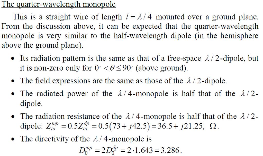
44 Monopoles A monopole is a dipole that has been divided into half at its center where it is fed against a ground plane. It is normally λ long (a 4 quarter-wavelength monopole). 44
45 45
46 Several important conclusions follow from the image theory The field distribution in the upper half-space is the same as that of the respective free-space dipole. The currents and charges on a monopole are the same as on the upper half of its dipole counterpart but the terminal voltage is only half that of the dipole. The input impedance of a monopole is therefore only half that of the respective dipole: The total radiated power of a monopole is half the power radiated by its dipole counterpart since it radiates in half-space (but its field is the same). As a result, the beam solid angle of the monopole is half that of the respective dipole and its directivity is twice the directivity of the dipole: 46
47 47

48 Some approximate formulas for rapid calculations of the input resistance of a dipole and the respective monopole: 48

49 Horizontal current element above a perfectly conducting plane 49
50 Where Using the far field approximation 50
51 The fare field normalized pattern 51
52 As the height increases beyond a wavelength (h>λ), scalloping appears with the number of lobes being 52
53 The radiated power and the radiation resistance It is also obvious that if h=0, then R r and Π=0. This is to be expected because the dipole is short-circuited by the ground plane. 53
54 Radiation Intensity The maximum value depends on whether βh is less than π/2 or greater: Maximum directivity For small βh 54
Linear Wire Antennas. EE-4382/ Antenna Engineering
 Linear Wire Antennas EE-438/5306 - Antenna Engineering Outline Introduction Infinitesimal Dipole Small Dipole Finite Length Dipole Half-Wave Dipole Ground Effect Constantine A. Balanis, Antenna Theory:
Resonant Antennas: Wires and Patches
 Resonant Antennas: Wires and Patches Dipole Antennas Antenna 48 Current distribution approximation Un-normalized pattern: and Antenna 49 Radiating power: For half-wave dipole and,, or at exact resonance.
Half-Wave Dipole. Radiation Resistance. Antenna Efficiency
 Antennas Simple Antennas Isotropic radiator is the simplest antenna mathematically Radiates all the power supplied to it, equally in all directions Theoretical only, can t be built Useful as a reference:
Antenna Parameters. Ranga Rodrigo. University of Moratuwa. December 15, 2008
 Antenna Parameters Ranga Rodrigo University of Moratuwa December 15, 2008 Ranga Rodrigo (University of Moratuwa) Antenna Parameters December 15, 2008 1 / 47 Summary of Last Week s Lecture 90 o Radiation
Investigation of Board-Mounted Omni- Directional Antennas for WLAN- Applications
 Investigation of Board-Mounted Omni- Directional Antennas for WLAN- Applications Luis Quineche ISE Master Student EEE: Communications Engineering Index Description of Problem Thesis Task Background Theory
Monopole Antennas. Prof. Girish Kumar Electrical Engineering Department, IIT Bombay. (022)
") Monopole Antennas Prof. Girish Kumar Electrical Engineering Department, IIT Bombay gkumar@ee.iitb.ac.in (022) 2576 7436 Monopole Antenna on Infinite Ground Plane Quarter-wavelength monopole Antenna on
Monopole Antennas Prof. Girish Kumar Electrical Engineering Department, IIT Bombay gkumar@ee.iitb.ac.in (022) 2576 7436 Monopole Antenna on Infinite Ground Plane Quarter-wavelength monopole Antenna on
Travelling Wave, Broadband, and Frequency Independent Antennas. EE-4382/ Antenna Engineering
 Travelling Wave, Broadband, and Frequency Independent Antennas EE-4382/5306 - Antenna Engineering Outline Traveling Wave Antennas Introduction Traveling Wave Antennas: Long Wire, V Antenna, Rhombic Antenna
UNIT Explain the radiation from two-wire. Ans: Radiation from Two wire
 UNIT 1 1. Explain the radiation from two-wire. Radiation from Two wire Figure1.1.1 shows a voltage source connected two-wire transmission line which is further connected to an antenna. An electric field
Impedance and Loop Antennas
 Impedance and Loop Antennas Ranga Rodrigo University of Moratuwa January 4, 2009 Ranga Rodrigo (University of Moratuwa) Impedance and Loop Antennas January 4, 2009 1 / 41 Gain Summary of Last Week s Lecture
Notes 21 Introduction to Antennas
 ECE 3317 Applied Electromagnetic Waves Prof. David R. Jackson Fall 018 Notes 1 Introduction to Antennas 1 Introduction to Antennas Antennas An antenna is a device that is used to transmit and/or receive
UNIVERSITI MALAYSIA PERLIS
 UNIVERSITI MALAYSIA PERLIS SCHOOL OF COMPUTER & COMMUNICATIONS ENGINEERING EKT 341 LABORATORY MODULE LAB 2 Antenna Characteristic 1 Measurement of Radiation Pattern, Gain, VSWR, input impedance and reflection
Traveling Wave Antennas
 Traveling Wave Antennas Antennas with open-ended wires where the current must go to zero (dipoles, monopoles, etc.) can be characterized as standing wave antennas or resonant antennas. The current on these
CHAPTER 5 THEORY AND TYPES OF ANTENNAS. 5.1 Introduction
 CHAPTER 5 THEORY AND TYPES OF ANTENNAS 5.1 Introduction Antenna is an integral part of wireless communication systems, considered as an interface between transmission line and free space [16]. Antenna
CHAPTER 5 PRINTED FLARED DIPOLE ANTENNA
 CHAPTER 5 PRINTED FLARED DIPOLE ANTENNA 5.1 INTRODUCTION This chapter deals with the design of L-band printed dipole antenna (operating frequency of 1060 MHz). A study is carried out to obtain 40 % impedance
EMG4066:Antennas and Propagation Exp 1:ANTENNAS MMU:FOE. To study the radiation pattern characteristics of various types of antennas.
 OBJECTIVES To study the radiation pattern characteristics of various types of antennas. APPARATUS Microwave Source Rotating Antenna Platform Measurement Interface Transmitting Horn Antenna Dipole and Yagi
ANTENNA THEORY. Analysis and Design. CONSTANTINE A. BALANIS Arizona State University. JOHN WILEY & SONS New York Chichester Brisbane Toronto Singapore
 ANTENNA THEORY Analysis and Design CONSTANTINE A. BALANIS Arizona State University JOHN WILEY & SONS New York Chichester Brisbane Toronto Singapore Contents Preface xv Chapter 1 Antennas 1 1.1 Introduction
Antennas Prof. Girish Kumar Department of Electrical Engineering Indian Institute of Technology, Bombay. Module 2 Lecture - 10 Dipole Antennas-III
 Antennas Prof. Girish Kumar Department of Electrical Engineering Indian Institute of Technology, Bombay Module 2 Lecture - 10 Dipole Antennas-III Hello, and welcome to todays lecture on Dipole Antenna.
HHTEHHH THEORY ANALYSIS AND DESIGN. CONSTANTINE A. BALANIS Arizona State University
 HHTEHHH THEORY ANALYSIS AND DESIGN CONSTANTINE A. BALANIS Arizona State University JOHN WILEY & SONS, INC. New York Chichester Brisbane Toronto Singapore Contents Preface V CHAPTER 1 ANTENNAS 1.1 Introduction
EC ANTENNA AND WAVE PROPAGATION
 EC6602 - ANTENNA AND WAVE PROPAGATION FUNDAMENTALS PART-B QUESTION BANK UNIT 1 1. Define the following parameters w.r.t antenna: i. Radiation resistance. ii. Beam area. iii. Radiation intensity. iv. Directivity.
Antenna Fundamentals Basics antenna theory and concepts
 Antenna Fundamentals Basics antenna theory and concepts M. Haridim Brno University of Technology, Brno February 2017 1 Topics What is antenna Antenna types Antenna parameters: radiation pattern, directivity,
DEPARTMENT OF ELECTRONICS & COMMUNICATION ENGINEERING SUBJECT NAME:
 Chendu College of Engineering & Technology (Approved by AICTE, New Delhi and Affiliated to Anna University) Zamin Endathur, Madurantakam, Kancheepuram, District 603311. DEPARTMENT OF ELECTRONICS & COMMUNICATION
You will need the following pieces of equipment to complete this experiment: Wilkinson power divider (3-port board with oval-shaped trace on it)
") UNIVERSITY OF TORONTO FACULTY OF APPLIED SCIENCE AND ENGINEERING The Edward S. Rogers Sr. Department of Electrical and Computer Engineering ECE422H1S: RADIO AND MICROWAVE WIRELESS SYSTEMS EXPERIMENT 1:
UNIVERSITY OF TORONTO FACULTY OF APPLIED SCIENCE AND ENGINEERING The Edward S. Rogers Sr. Department of Electrical and Computer Engineering ECE422H1S: RADIO AND MICROWAVE WIRELESS SYSTEMS EXPERIMENT 1:
UNIT Write short notes on travelling wave antenna? Ans: Travelling Wave Antenna
 UNIT 4 1. Write short notes on travelling wave antenna? Travelling Wave Antenna Travelling wave or non-resonant or aperiodic antennas are those antennas in which there is no reflected wave i.e., standing
( ) 2 ( ) 3 ( ) + 1. cos! t " R / v p 1 ) H =! ˆ" I #l ' $ 2 ' 2 (18.20) * + ! ˆ& "I #l ' $ 2 ' , ( βr << 1. "l ' E! ˆR I 0"l ' cos& + ˆ& 0
 2 ( ) 3 ( ) + 1. cos! t R / v p 1 ) H =! ˆ I #l ' $ 2 ' 2 (18.20) * + ! ˆ& I #l ' $ 2 ' , ( βr << 1. l ' E! ˆR I 0l ' cos& + ˆ& 0") Summary Chapter 8. This last chapter treats the problem of antennas and radiation from antennas. We start with the elemental electric dipole and introduce the idea of retardation of potentials and fields
Summary Chapter 8. This last chapter treats the problem of antennas and radiation from antennas. We start with the elemental electric dipole and introduce the idea of retardation of potentials and fields
SI TECHNICAL 2018 UNIT IV QUESTION BANK
 SI TECHNICAL 2018 UNIT IV QUESTION BANK 1. In what range of frequencies are most omnidirectional horizontally polarized antennas used? A. VHF, UHF B. VLF, LF C. SH, EHF D. MF, HF 2. If the current ratios
Antenna? What s That? Chet Thayer WA3I
 Antenna? What s That? Chet Thayer WA3I Space: The Final Frontier Empty Space (-Time) Four dimensional region that holds everything Is Permeable : It requires energy to set up a magnetic field within it.
Millimetre-wave Phased Array Antennas for Mobile Terminals
 Millimetre-wave Phased Array Antennas for Mobile Terminals Master s Thesis Alberto Hernández Escobar Aalborg University Department of Electronic Systems Fredrik Bajers Vej 7B DK-9220 Aalborg Contents
The Basics of Patch Antennas, Updated
 The Basics of Patch Antennas, Updated By D. Orban and G.J.K. Moernaut, Orban Microwave Products www.orbanmicrowave.com Introduction This article introduces the basic concepts of patch antennas. We use
TABLE OF CONTENTS. 2.2 Monopoles Characteristics of a l/4 Monopole Folded Monopoles. 2.3 Bibliography. Antenna Fundamentals 1-1
 TABLE OF CONTENTS 2.1 Dipoles 2.1.1 Radiation Patterns 2.1.2 Effects of Conductor Diameter 2.1.3 Feed Point Impedance 2.1.4 Effect of Frequency on Radiation Pattern 2.1.5 Folded Dipoles 2.1.6 Vertical
Antennas 1. Antennas
 Antennas Antennas 1! Grading policy. " Weekly Homework 40%. " Midterm Exam 30%. " Project 30%.! Office hour: 3:10 ~ 4:00 pm, Monday.! Textbook: Warren L. Stutzman and Gary A. Thiele, Antenna Theory and
Electronically Steerable planer Phased Array Antenna
 Electronically Steerable planer Phased Array Antenna Amandeep Kaur Department of Electronics and Communication Technology, Guru Nanak Dev University, Amritsar, India Abstract- A planar phased-array antenna
INSTITUTE OF AERONAUTICAL ENGINEERING Dundigal, Hyderabad ELECTRONICS AND COMMUNIACTION ENGINEERING QUESTION BANK
 INSTITUTE OF AERONAUTICAL ENGINEERING Dundigal, Hyderabad - 500 04 ELECTRONICS AND COMMUNIACTION ENGINEERING QUESTION BANK Course Name : Antennas and Wave Propagation (AWP) Course Code : A50418 Class :
Continuous Arrays Page 1. Continuous Arrays. 1 One-dimensional Continuous Arrays. Figure 1: Continuous array N 1 AF = I m e jkz cos θ (1) m=0
 m=0") Continuous Arrays Page 1 Continuous Arrays 1 One-dimensional Continuous Arrays Consider the 2-element array we studied earlier where each element is driven by the same signal (a uniform excited array),
Continuous Arrays Page 1 Continuous Arrays 1 One-dimensional Continuous Arrays Consider the 2-element array we studied earlier where each element is driven by the same signal (a uniform excited array),
Fundamentals of Antennas. Prof. Ely Levine
 Fundamentals of Antennas Prof. Ely Levine levineel@zahav.net.il 1 Chapter 3 Wire Antennas 2 Types of Antennas 3 Isotropic Antenna Isotropic radiator is the simplest antenna mathematically Radiates all
Low-Profile and Small Capacitively Fed VHF Antenna
 Progress In Electromagnetics Research Letters, Vol. 60, 31 38, 2016 Low-Profile and Small Capacitively Fed VHF Antenna Yaakoub Taachouche 1, *, Franck Colombel 1, Mohamed Himdi 1, and Antoine Guenin 2
CHAPTER 8 ANTENNAS 1
 CHAPTER 8 ANTENNAS 1 2 Antennas A good antenna works A bad antenna is a waste of time & money Antenna systems can be very inexpensive and simple They can also be very expensive 3 Antenna Considerations
ANT5: Space and Line Current Radiation
 In this lecture, we study the general case of radiation from z-directed spatial currents. The far-field radiation equations that result from this treatment form some of the foundational principles of all
Design of Star-Shaped Microstrip Patch Antenna for Ultra Wideband (UWB) Applications
 Applications") Design of Star-Shaped Microstrip Patch Antenna for Ultra Wideband (UWB) Applications Mustafa Abu Nasr 1, Mohamed K. Ouda 2 and Samer O. Ouda 3 1 Engineering Department, Al Azhar University, Gaza, Palestine,
Design of Star-Shaped Microstrip Patch Antenna for Ultra Wideband (UWB) Applications Mustafa Abu Nasr 1, Mohamed K. Ouda 2 and Samer O. Ouda 3 1 Engineering Department, Al Azhar University, Gaza, Palestine,
Beyond the Long Wavelength Limit
 Beyond the Long Wavelength Limit Thus far, we have studied EM radiation by oscillating charges and current confined to a volume of linear size much smaller than the wavelength λ = πc/ω. In these notes,
Antennas & wave Propagation ASSIGNMENT-I
 Shri Vishnu Engineering College for Women :: Bhimavaram Department of Electronics & Communication Engineering Antennas & wave Propagation 1. Define the terms: i. Antenna Aperture ii. Beam Width iii. Aperture
Planar Radiators 1.1 INTRODUCTION
 1 Planar Radiators 1.1 INTRODUCTION The rapid development of wireless communication systems is bringing about a wave of new wireless devices and systems to meet the demands of multimedia applications.
Radiation and Antennas
 Chapter 9 Radiation and Antennas. Basic Formulations 2. Hertzian Dipole Antenna 3. Linear Antennas An antenna is a device to transmit or receive electromagnetic power more efficiently with a more directive
Antenna Theory and Design
 Antenna Theory and Design Antenna Theory and Design Associate Professor: WANG Junjun 王珺珺 School of Electronic and Information Engineering, Beihang University F1025, New Main Building wangjunjun@buaa.edu.cn
Antenna Design Seminar
 Antenna Design Seminar What we are going to cover This seminar will cover the design concepts of a variety of broadcast antennas that relates to the design of TV and FM antennas. We will first look at
Dipole Antennas. Prof. Girish Kumar Electrical Engineering Department, IIT Bombay. (022)
") Dipole Antennas Prof. Girish Kumar Electrical Engineering Department, IIT Bombay gkumar@ee.iitb.ac.in (022) 2576 7436 Infinitesimal Dipole An infinitesimally small current element is called the Hertz Dipole
Dipole Antennas Prof. Girish Kumar Electrical Engineering Department, IIT Bombay gkumar@ee.iitb.ac.in (022) 2576 7436 Infinitesimal Dipole An infinitesimally small current element is called the Hertz Dipole
Antenna Fundamentals
 HTEL 104 Antenna Fundamentals The antenna is the essential link between free space and the transmitter or receiver. As such, it plays an essential part in determining the characteristics of the complete
DESIGN OF OMNIDIRECTIONAL HIGH-GAIN AN- TENNA WITH BROADBAND RADIANT LOAD IN C WAVE BAND
 Progress In Electromagnetics Research C, Vol. 33, 243 258, 212 DESIGN OF OMNIDIRECTIONAL HIGH-GAIN AN- TENNA WITH BROADBAND RADIANT LOAD IN C WAVE BAND S. Lin *, M.-Q. Liu, X. Liu, Y.-C. Lin, Y. Tian,
25. Antennas II. Radiation patterns. Beyond the Hertzian dipole - superposition. Directivity and antenna gain. More complicated antennas
 25. Antennas II Radiation patterns Beyond the Hertzian dipole - superposition Directivity and antenna gain More complicated antennas Impedance matching Reminder: Hertzian dipole The Hertzian dipole is
Antenna Theory and Design
 Antenna Theory and Design Antenna Theory and Design Associate Professor: WANG Junjun 王珺珺 School of Electronic and Information Engineering, Beihang University wangjunjun@buaa.edu.cn 13426405497 Chapter
KINGS COLLEGE OF ENGINEERING. DEPARTMENT OF ELECTRONICS AND COMMUNICATION ENGINEERING Academic Year (Even Sem) QUESTION BANK (AUTT-R2008)
 QUESTION BANK (AUTT-R2008)") KINGS COLLEGE OF ENGINEERING DEPARTMENT OF ELECTRONICS AND COMMUNICATION ENGINEERING Academic Year 2012-2013(Even Sem) QUESTION BANK (AUTT-R2008) SUBJECT CODE /NAME: EC 1352 / ANTENNEA AND WAVE PROPAGATION
KINGS COLLEGE OF ENGINEERING DEPARTMENT OF ELECTRONICS AND COMMUNICATION ENGINEERING Academic Year 2012-2013(Even Sem) QUESTION BANK (AUTT-R2008) SUBJECT CODE /NAME: EC 1352 / ANTENNEA AND WAVE PROPAGATION
stacking broadside collinear
 stacking broadside collinear There are three primary types of arrays, collinear, broadside, and endfire. Collinear is pronounced co-linear, and we may think it is spelled colinear, but the correct spelling
COUPLED SECTORIAL LOOP ANTENNA (CSLA) FOR ULTRA-WIDEBAND APPLICATIONS *
 FOR ULTRA-WIDEBAND APPLICATIONS *") COUPLED SECTORIAL LOOP ANTENNA (CSLA) FOR ULTRA-WIDEBAND APPLICATIONS * Nader Behdad, and Kamal Sarabandi Department of Electrical Engineering and Computer Science University of Michigan, Ann Arbor, MI,
COUPLED SECTORIAL LOOP ANTENNA (CSLA) FOR ULTRA-WIDEBAND APPLICATIONS * Nader Behdad, and Kamal Sarabandi Department of Electrical Engineering and Computer Science University of Michigan, Ann Arbor, MI,
l s Nikolova Trans. on Antennas and Propagation, vol. AP-28, No. 5, pp , Sept Equation Section 11 1.
 LECTURE 11: Practical Dipole/Monopole Geometries. Matching Techniques for Dipole/Monopole Feeds (The folded dipole antenna. Conical skirt monopoles. Sleeve antennas. Turnstile antenna. Impedance matching
Chapter 3 Broadside Twin Elements 3.1 Introduction
 Chapter 3 Broadside Twin Elements 3. Introduction The focus of this chapter is on the use of planar, electrically thick grounded substrates for printed antennas. A serious problem with these substrates
Design and Development of a 2 1 Array of Slotted Microstrip Line Fed Shorted Patch Antenna for DCS Mobile Communication System
 Wireless Engineering and Technology, 2013, 4, 59-63 http://dx.doi.org/10.4236/wet.2013.41009 Published Online January 2013 (http://www.scirp.org/journal/wet) 59 Design and Development of a 2 1 Array of
KULLIYYAH OF ENGINEERING
 KULLIYYAH OF ENGINEERING DEPARTMENT OF ELECTRICAL & COMPUTER ENGINEERING ANTENNA AND WAVE PROPAGATION LABORATORY (ECE 4103) EXPERIMENT NO 3 RADIATION PATTERN AND GAIN CHARACTERISTICS OF THE DISH (PARABOLIC)
ANTENNA THEORY ANALYSIS AND DESIGN
 ANTENNA THEORY ANALYSIS AND DESIGN THIRD EDITION Constantine A. Balanis WILEY- INTERSCIENCE A JOHN WILEY & SONS. INC.. PUBLICATION ial iel pi ial ial ial IBl ial ial ial pi Sl Contents Preface Xlll 1 Antennas
Antennas and Propagation. Chapter 4: Antenna Types
 Antennas and Propagation : Antenna Types 4.4 Aperture Antennas High microwave frequencies Thin wires and dielectrics cause loss Coaxial lines: may have 10dB per meter Waveguides often used instead Aperture
In this lecture, we study the general case of radiation from z-directed spatial currents. The far-
 In this lecture, we study the general case of radiation from z-directed spatial currents. The far- field radiation equations that result from this treatment form some of the foundational principles of
Experimental Study of Sleeve Antennas Using Variable Capacitors
 Experimental Study of Sleeve Antennas Using Variable Capacitors # Kengo Nishimoto, Ryosuke Umeno, Nobuyasu Takemura, Toru Fukasawa, Masataka Ohtsuka, Shigeru Makino Mitsubishi Electric Corporation 5-1-1
ANTENNAS. I will mostly be talking about transmission. Keep in mind though, whatever is said about transmission is true of reception.
 Reading 37 Ron Bertrand VK2DQ http://www.radioelectronicschool.com ANTENNAS The purpose of an antenna is to receive and/or transmit electromagnetic radiation. When the antenna is not connected directly
An Introduction to Antennas
 May 11, 010 An Introduction to Antennas 1 Outline Antenna definition Main parameters of an antenna Types of antennas Antenna radiation (oynting vector) Radiation pattern Far-field distance, directivity,
HIGH GAIN AND LOW COST ELECTROMAGNETICALLY COUPLED RECTAGULAR PATCH ANTENNA
 HIGH GAIN AND LOW COST ELECTROMAGNETICALLY COUPLED RECTAGULAR PATCH ANTENNA Raja Namdeo, Sunil Kumar Singh Abstract: This paper present high gain and wideband electromagnetically coupled patch antenna.
KINGS COLLEGE OF ENGINEERING DEPARTMENT OF ELECTRONICS AND COMMUNICATION ENGINEERING QUESTION BANK
 KINGS COLLEGE OF ENGINEERING DEPARTMENT OF ELECTRONICS AND COMMUNICATION ENGINEERING QUESTION BANK SUB.NAME : ANTENNAS & WAVE PROPAGATION SUB CODE : EC 1352 YEAR : III SEMESTER : VI UNIT I: ANTENNA FUNDAMENTALS
2.5.3 Antenna Temperature
 ECEn 665: Antennas and Propagation for Wireless Communications 36.5.3 Antenna Temperature We now turn to thermal noise received by an antenna. An antenna in a warm environment receives not only a signal
Antenna Engineering Lecture 3: Basic Antenna Parameters
 Antenna Engineering Lecture 3: Basic Antenna Parameters ELC 405a Fall 2011 Department of Electronics and Communications Engineering Faculty of Engineering Cairo University 2 Outline 1 Radiation Pattern
DESIGN CONSIDERATION OF ARRAYS FOR THE STUDIES OF RADIATION PATTERN OF LOG PERIODIC DIPOLE ARRAY ANTENNA AT DIFFERENT FREQUENCIES
 DESIGN CONSIDERATION OF ARRAYS FOR THE STUDIES OF RADIATION PATTERN OF LOG PERIODIC DIPOLE ARRAY ANTENNA AT DIFFERENT FREQUENCIES 1 Atanu Nag, 2 Kanchan Acharjee, 3 Kausturi Chatterjee, 4 Swastika Banerjee
Antennas Prof. Girish Kumar Department of Electrical Engineering India Institute of Technology, Bombay. Module - 1 Lecture - 1 Antennas Introduction-I
 Antennas Prof. Girish Kumar Department of Electrical Engineering India Institute of Technology, Bombay Module - 1 Lecture - 1 Antennas Introduction-I Hello everyone. Welcome to the exciting world of antennas.
10 Antenna gain, beam pattern, directivity
 10 Antenna gain, beam pattern, directivity Adipoleantenna(oracloselyrelatedmonopoletobestudiedinLecture 18) is a near perfect radiator for purposes of broadcasting that is, sending waves of equal amplitudes
BHARATHIDASAN ENGINEERING COLLEGE NATTARAMPALLI Frequently Asked Questions (FAQ) Unit 1
 Unit 1") BHARATHIDASAN ENGINEERING COLLEGE NATTARAMPALLI 635854 Frequently Asked Questions (FAQ) Unit 1 Degree / Branch : B.E / ECE Sem / Year : 3 rd / 6 th Sub Name : Antennas & Wave Propagation Sub Code : EC6602
BHARATHIDASAN ENGINEERING COLLEGE NATTARAMPALLI 635854 Frequently Asked Questions (FAQ) Unit 1 Degree / Branch : B.E / ECE Sem / Year : 3 rd / 6 th Sub Name : Antennas & Wave Propagation Sub Code : EC6602
Modeling of a Patch- Antenna
 Master Thesis Modeling of a Patch- Antenna by Yingbin Wu Supervised by Prof. Dr. -Ing. K. Solbach 24.05.2007 Content Introduction Modeling of disk-loaded monopoles Modeling of a Patch-Antenna Conclusion
Can an Antenna Be Cut Into Pieces (Without Affecting Its Radiation)?
?") Can an Antenna Be Cut Into Pieces (Without Affecting Its Radiation)? David J. Jefferies School of Electronics and Physical Sciences, University of Surrey, Guildford, Surrey GU2 7XH, UK Kirk T. McDonald
Can an Antenna Be Cut Into Pieces (Without Affecting Its Radiation)? David J. Jefferies School of Electronics and Physical Sciences, University of Surrey, Guildford, Surrey GU2 7XH, UK Kirk T. McDonald
A Broadband Omnidirectional Antenna Array for Base Station
 Progress In Electromagnetics Research C, Vol. 54, 95 101, 2014 A Broadband Omnidirectional Antenna Array for Base Station Bo Wang 1, *, Fushun Zhang 1,LiJiang 1, Qichang Li 2, and Jian Ren 1 Abstract A
RECOMMENDATION ITU-R BS * LF and MF transmitting antennas characteristics and diagrams **
 Rec. ITU-R BS.1386-1 1 RECOMMENDATION ITU-R BS.1386-1 * LF and MF transmitting antennas characteristics and diagrams ** (Question ITU-R 201/10) (1998-2001) The ITU Radiocommunication Assembly, considering
Broadband Antenna. Broadband Antenna. Chapter 4
 1 Chapter 4 Learning Outcome At the end of this chapter student should able to: To design and evaluate various antenna to meet application requirements for Loops antenna Helix antenna Yagi Uda antenna
A Compact Dual-Polarized Antenna for Base Station Application
 Progress In Electromagnetics Research Letters, Vol. 59, 7 13, 2016 A Compact Dual-Polarized Antenna for Base Station Application Guan-Feng Cui 1, *, Shi-Gang Zhou 2,Shu-XiGong 1, and Ying Liu 1 Abstract
DESIGN AND STUDY OF INSET FEED SQUARE MICROSTRIP PATCH ANTENNA FOR S-BAND APPLICATION
 DESIGN AND STUDY OF INSET FEED SQUARE MICROSTRIP PATCH ANTENNA FOR S-BAND APPLICATION 1 Priya Upadhyay, 2 Richa Sharma 1 M-tech Electronics and Communication, Department of ECE, Ajay Kumar Garg Engineering
DESIGN OF PRINTED YAGI ANTENNA WITH ADDI- TIONAL DRIVEN ELEMENT FOR WLAN APPLICA- TIONS
 Progress In Electromagnetics Research C, Vol. 37, 67 81, 013 DESIGN OF PRINTED YAGI ANTENNA WITH ADDI- TIONAL DRIVEN ELEMENT FOR WLAN APPLICA- TIONS Jafar R. Mohammed * Communication Engineering Department,
Rec. ITU-R F RECOMMENDATION ITU-R F *
 Rec. ITU-R F.162-3 1 RECOMMENDATION ITU-R F.162-3 * Rec. ITU-R F.162-3 USE OF DIRECTIONAL TRANSMITTING ANTENNAS IN THE FIXED SERVICE OPERATING IN BANDS BELOW ABOUT 30 MHz (Question 150/9) (1953-1956-1966-1970-1992)
Coupled Sectorial Loop Antenna (CSLA) for Ultra Wideband Applications
 for Ultra Wideband Applications") Coupled Sectorial Loop Antenna (CSLA) for Ultra Wideband Applications N. Behdad and K. Sarabandi Presented by Nader Behdad at Antenna Application Symposium, Monticello, IL, Sep 2004 Email: behdad@ieee.org
Coupled Sectorial Loop Antenna (CSLA) for Ultra Wideband Applications N. Behdad and K. Sarabandi Presented by Nader Behdad at Antenna Application Symposium, Monticello, IL, Sep 2004 Email: behdad@ieee.org
"Natural" Antennas. Mr. Robert Marcus, PE, NCE Dr. Bruce C. Gabrielson, NCE. Security Engineering Services, Inc. PO Box 550 Chesapeake Beach, MD 20732
 Published and presented: AFCEA TEMPEST Training Course, Burke, VA, 1992 Introduction "Natural" Antennas Mr. Robert Marcus, PE, NCE Dr. Bruce C. Gabrielson, NCE Security Engineering Services, Inc. PO Box
Newsletter 3.1. Antenna Magus version 3.1 released! New antennas in the database. Square pin-fed septum horn. July 2011
 Newsletter 3.1 July 2011 Antenna Magus version 3.1 released! Antenna Magus 3.0 was such a feature laden release that not all of the new features could be mentioned in the newsletter, so we decided to rather
ON THE RADIATION PATTERN OF THE L-SHAPED WIRE ANTENNA
 Progress In Electromagnetics Research M, Vol. 6, 91 105, 2009 ON THE RADIATION PATTERN OF THE L-SHAPED WIRE ANTENNA A. Andújar, J. Anguera, and C. Puente Technology and Intellectual Property Rights Department
Beams and Directional Antennas
 Beams and Directional Antennas The Horizontal Dipole Our discussion in this chapter is about the more conventional horizontal dipole and the simplified theory behind dipole based designs. For clarity,
DESIGNING A PATCH ANTENNA FOR DOPPLER SYSTEMS
 DESIGNING A PATCH ANTENNA FOR DOPPLER SYSTEMS Doppler Requirements for Antennas Range Determines power consumption Defines frequency band R max = 4 P t GσA e 4π 2 S min Narrow Bandwidth Tolerance range
Chapter 6 Antenna Basics. Dipoles, Ground-planes, and Wires Directional Antennas Feed Lines
 Chapter 6 Antenna Basics Dipoles, Ground-planes, and Wires Directional Antennas Feed Lines Some General Rules Bigger is better. (Most of the time) Higher is better. (Most of the time) Lower SWR is better.
ANTENNAS 101 An Introduction to Antennas for Ham Radio. Lee KD4RE
 ANTENNAS 101 An Introduction to Antennas for Ham Radio Lee KD4RE Prepared for Presentation at the Vienna Wireless Society, 13 January 2017 So What is an Antenna Anyway? We are all familiar with wire antennas
Proximity fed gap-coupled half E-shaped microstrip antenna array
 Sādhanā Vol. 40, Part 1, February 2015, pp. 75 87. c Indian Academy of Sciences Proximity fed gap-coupled half E-shaped microstrip antenna array AMIT A DESHMUKH 1, and K P RAY 2 1 Department of Electronics
Chapter 7 Design of the UWB Fractal Antenna
 Chapter 7 Design of the UWB Fractal Antenna 7.1 Introduction F ractal antennas are recognized as a good option to obtain miniaturization and multiband characteristics. These characteristics are achieved
Broadband Microstrip Antennas
 Broadband Microstrip Antennas Prof. Girish Kumar Electrical Engineering Department, IIT Bombay gkumar@ee.iitb.ac.in (022) 2576 7436 MSA BW Variation with h and f MSA Broadband Using Multi-Resonators Broad
ELEC 425 Interference Control in Electronics Lecture 7(a) Introduction to Antennas: Terminology
 Introduction to Antennas: Terminology") Dr. Gregory J. Mazzaro Fall 017 ELEC 45 Interference Control in Electronics Lecture 7(a) Introduction to Antennas: Terminology Chapter 9 THE CITADEL, THE MILITARY COLLEGE OF SOUTH CAROLINA 171 Moultrie
Dr. Gregory J. Mazzaro Fall 017 ELEC 45 Interference Control in Electronics Lecture 7(a) Introduction to Antennas: Terminology Chapter 9 THE CITADEL, THE MILITARY COLLEGE OF SOUTH CAROLINA 171 Moultrie
A K-Band Flat Transmitarray Antenna with a Planar Microstrip Slot-Fed Patch Antenna Feeder
 Progress In Electromagnetics Research C, Vol. 64, 97 104, 2016 A K-Band Flat Transmitarray Antenna with a Planar Microstrip Slot-Fed Patch Antenna Feeder Lv-Wei Chen and Yuehe Ge * Abstract A thin phase-correcting
Antenna & Propagation. Antenna Parameters
 For updated version, please click on http://ocw.ump.edu.my Antenna & Propagation Antenna Parameters by Nor Hadzfizah Binti Mohd Radi Faculty of Electric & Electronics Engineering hadzfizah@ump.edu.my Chapter
I J E E Volume 5 Number 1 January-June 2013 pp
 I J E E Volume 5 Number 1 January-June 2013 pp. 21-25 Serials Publications, ISSN : 0973-7383 Various Antennas and Its Applications in Wireless Domain: A Review Paper P.A. Ambresh 1, P.M. Hadalgi 2 and
Chapter 6 Broadband Antenna. 1. Loops antenna 2. Heliksantenna 3. Yagi uda antenna
 Chapter 6 Broadband Antenna 1. Loops antenna 2. Heliksantenna 3. Yagi uda antenna 1 Design A broadband antenna should have acceptable performance (determined by its pattern, gain and/or feed-point impedance)
Small Planar Antenna for WLAN Applications
 Small Planar Antenna for WLAN Applications # M. M. Yunus 1,2, N. Misran 2,3 and M. T. Islam 3 1 Faculty of Electronics and Computer Engineering, Universiti Teknikal Malaysia Melaka 2 Faculty of Engineering,
Broadband Dual Polarized Space-Fed Antenna Arrays with High Isolation
 Progress In Electromagnetics Research C, Vol. 55, 105 113, 2014 Broadband Dual Polarized Space-Fed Antenna Arrays with High Isolation Prashant K. Mishra 1, *, Dhananjay R. Jahagirdar 1,andGirishKumar 2
ECEn 665: Antennas and Propagation for Wireless Communications 48. Since the integrand is periodic, we can change the integration limits to
 ECEn 665: Antennas and Propagation for Wireless Communications 48 3.3 Loop Antenna An electric dipole antenna radiates an electric field that is aligned with the dipole and a magnetic field that radiates
Antennas 101 Don t Be a 0.97 db Weakling! Ward Silver NØAX
 Antennas 101 Don t Be a 0.97 db Weakling! Ward Silver NØAX Overview Antennas 101 2 Overview Basic Antennas: Ground Plane / Dipole How Gain and Nulls are Formed How Phased Arrays Work How Yagis Work (simplified)
3. LITERATURE REVIEW. 3.1 The Planar Inverted-F Antenna.
 3. LITERATURE REVIEW The commercial need for low cost and low profile antennas for mobile phones has drawn the interest of many researchers. While wire antennas, like the small helix and quarter-wavelength