Ferrite Loaded Cavities for RF Accelerating Systems
|
|
|
- Magdalen Douglas
- 6 years ago
- Views:
Transcription
1 Ferrite Loaded Cavities for RF Accelerating Systems Ian Gardner ISIS, RAL FFAG School September 2011
2 CONTENTS Introduction Ferrite relevant parameters Cavities or Co-axial resonators Tuning systems Common designs and equivalent circuits CERN Accelerator School, 1992 RF Engineering for Particle Accelerators Page 349, Ferrite loaded cavities Contains all formula and their derivation RN V1-V2.pdf?version=1
3

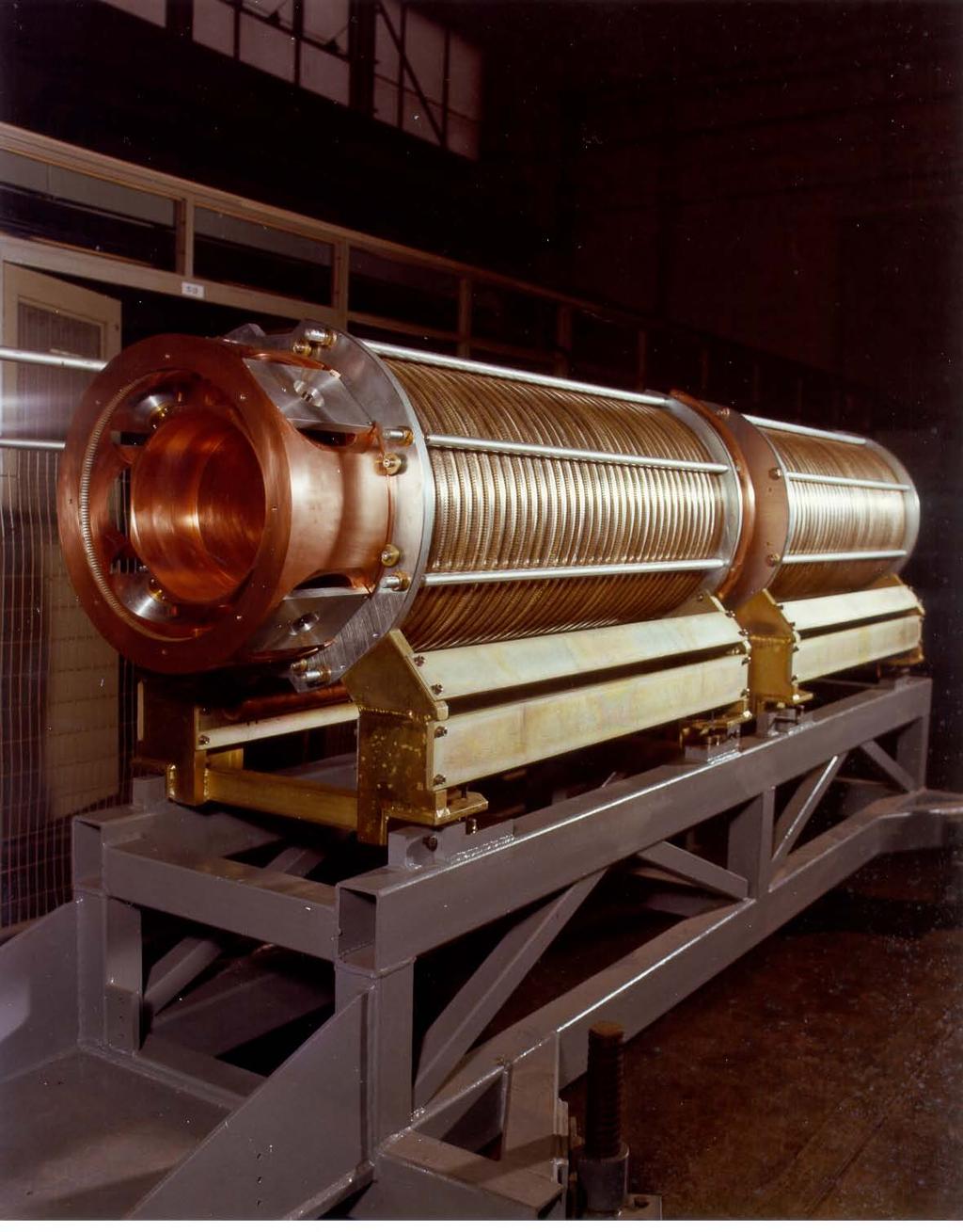
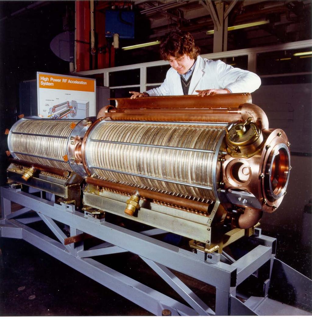
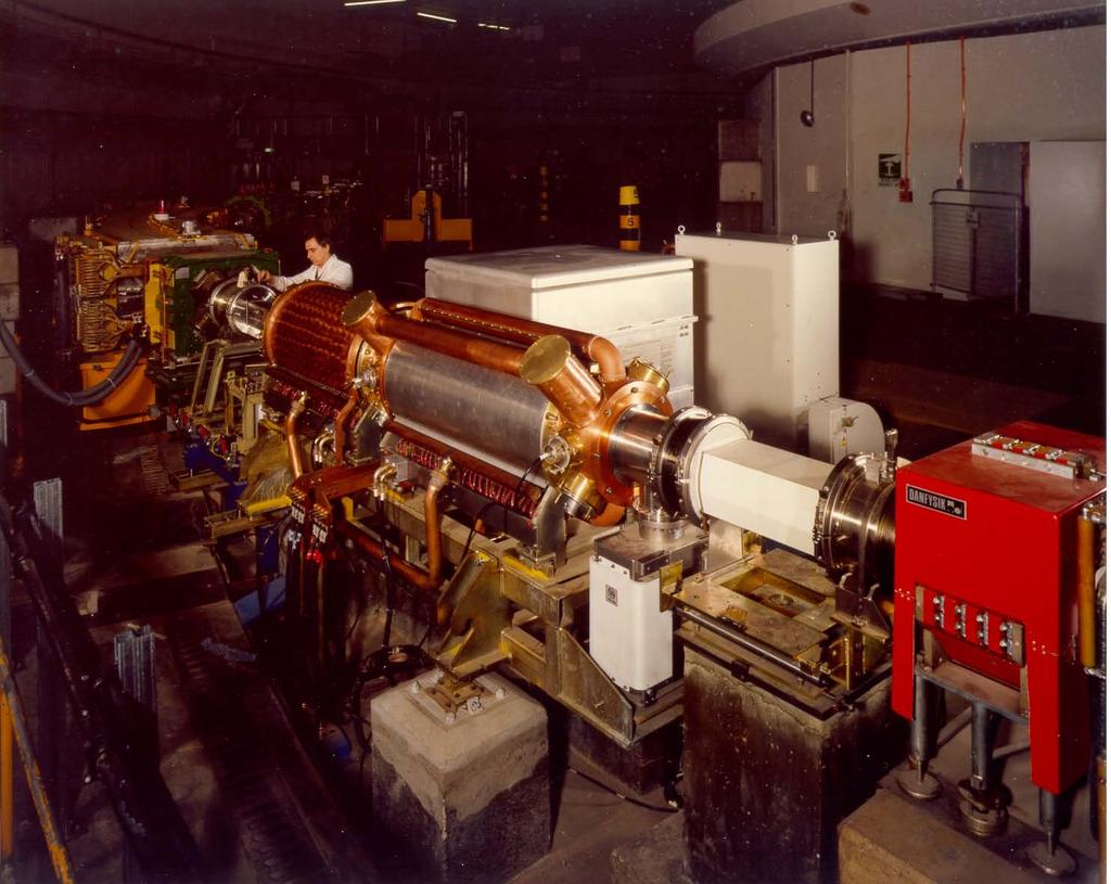
4 ISIS 1RF Cavity and HPD

5 Schematic of 1RF cavity and High Power Drive (HPD)

6 Cross section of an ISIS MHz cavity
7 APS LPRF Controls: Amplitude, Phase & Cavity Tuning. LVPS From LPRF Driver Amp. HPD Cavity Bias Supply BASIC RF SYSTEM
8 Ferrite Naturally occurring Ferrous Ferrite Fe 3 O 4 Fe 3+ (Fe 2+ Fe 3+ )O 4 structurally Fe 2+ may be replaced by any divalent metal of similar ion size Typical metals being; Nickel, Manganese, Magnesium, Cobalt, Copper, Zinc and Cadmium Wide range of ferrites available. See Philip s Ferroxcube, TDK Epcos, Toshiba and others. Most accelerator systems use NiZn based ferrites
9 Ferrite in RF Cavities Magnetic permeability Dielectric constant Resistivity Thermal conductivity Effects of temperature and electric and magnetic fields on the above parameters
10 Ferrite B-H loop with added ac field Incremental permeability μ r = B ac / μ o H ac varies with operating point
11 Plots of μ r against bias field for various types of Philip s ferrite
12 Ferrite Inductors Ferrite core increases inductance of a coil Hysteresis and eddy currents lead to losses Loss represented by assigning a complex value to the permeability. μ = μ' - j μ" Inductance impedance, Z = jωμl o = jωμ'l o + ωμ"l o = jωl + r L = μ'l o and r = μ"ωl o L o = the value of the air cored inductance
13 At resonance, Z = QωL = Qωμ'L o = (μ'qf)2πl o The factor (μ'qf) is often used as a figure of merit for ferrite materials in a given set up. For High Q; Q = ωl/r = ω μ' L o / ω μ" L o Q = μ' /μ"
14 Plots of μ' and μ" against frequency for different grades of Philip s Ferrite
15 Dielectric Constant of Ferrite Assign complex value to permittivity ε = ε' - jε" Similarly, this gives a resistance in parallel with a ferrite filled capacitor R = 1/ωεC o Where C o is the value of the air spaced capacitor and Q = ε'/ε" When C is resonated with a lossless coil. However, with NiZn ferrites, ε' remains constant at about 10 and does not vary with magnetic or electric fields. Up to 30 MHz ε" not found significant especially with copper cooling plates separating the ferrite.
16 Initial permeability as a function of temperature
17 Complex permeability as a function of frequency
18 80 60 mu value Ibias (A) 4M2 μ' value with bias current on ISIS
19 Tuning Range Frequency range is given by ω 2 = 1 / LC and L α μ μ max / μ min Variable frequency RF accelerating systems use shorted, ferrite loaded, co-axial transmission lines as inductances to resonate with the accelerating gap or drift tube capacitance.
20 Basic co-axial resonator circuit, short circuit at x = 0 Reactive impedance at the points AB without Cg is: Z = jz o tan(ωl/v) l = length of the line, v = signal velocity, Z o = characteristic impedance For ωl/v < π/2 i.e. 2πl/λ < π/2 and l < λ/4 Z is inductive and lets say = jωl Then L = (Z o /ω) tan(ωl/v) For resonance with Cg ω 2 = 1/LCg l = (v/ω) tan -1 (1/Z o ωcg)
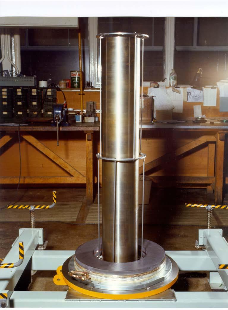
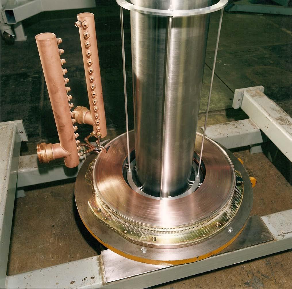
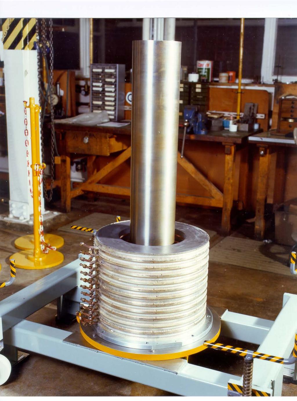
21 Typical resonator with ferrite toroids separated by air-cooled or fluid cooled gaps or water cooled metal plates. Electric field runs from inner conductor to outer and across insulating accelerating gap. Suitable gaps are required to prevent voltage breakdown. Vacuum required for beam pipe. Magnetic field circulates in the ferrite toroids.
22 The line capacitance is: C t = 2π ε e ε o / ln (r 3 /r 1 ) The line inductance is: L t = μ e μ o ln (r 3 /r 1 ) / 2π farads / metre henrys / metre Case 1 ε e = ε d 1 / [(k+ε(1- k)) (d 1 +d 2 )] ε e = The effective permittivity for an air filled gap Case 2 ε e = 1 / (1-k) ε e = Effective permittivity using cooled metal plates In both cases: μ e = (1+k(μ' 1)) d 1 / (d 1 +d 2 ) μ e = The effective permeability And: k = ln (r 3 /r 2 ) / ln (r 3 /r 1 ) Derivation see CAS appendix 1
23 The wave velocity in such a line is: v = 1 / (L t C t ) and: Z o = (L t /C t ) = c / (ε e μ e) Where c = the velocity of light = (1/2π) ln (r 3 /r 1 ) (μ e μ o /ε e ε o ) = 60 ln (r 3 /r 1 ) (μ e /ε e ) If the voltage at the capacitor is V g e iωt, the voltage and current are given by V = -V g e iωt sin(ωx/v) / sin(ωl/v) and: i = jv g e iωt cos(ωx/v) / (Z o cos(ωl/v)) The current is a maximum at the short circuit where x = 0 and the ratio of the current at x = - l to the current at x = 0 is cos (ωl/v) : 1 Derivations CAS Appendix 2
24 This difference is usually kept to ~ 10% to keep the RF magnetic field in the toroids at each end of the resonator similar. This means ωl / v < 26 i.e. much shorter than 90 or λ/4
25 RF Magnetic induction in the ferrite H = i / 2πr and B = μ'μ o i / 2πr B rfmax = μ'μ o i -l / (2πr 2 cos(ωl/v)) i -l = the current at x = -l In NiZn ferrites, where the saturation field is Tesla the maximum value of B rf is usually kept to 0.01 Tesla.
26 Q value and B rfmax Plot of μ'q f with peak rf field at 2.0 MHz for two ferrites Resonator length for a required peak gap voltage V g and lowest operating frequency ω, can be estimated from l = V g μ' / (μ e r 2 ln(r 3 /r 1 ) ω B rfmax ) Derivation CAS Appendix 3
27 Power dissipation in the ferrite Power dissipation in the resonator is: P = V g 2 / 2R = V g 2 / (2QωL) Mean Power / unit length P mean = V g 2 / (2lQωL) W / m Q will vary with voltage and frequency. The power dissipation along the resonator P(x) will vary with i 2. P(x) = P max cos 2 (ωx/v) P mean = P max (1 + (sin(2ωl/v) / 2ωl/v)) / 2 W / m W / m
28 Power density and temperature rise in the ferrite P dmax = P max (d 1 + d 2 ) / (π(r 3 2 r 22 )d 1 ) W / m 3 T = P d (d 1 /2) 2 / k Where k = Ferrite thermal conductivity in W / m. C Degrees P d = The power density in the ferrite in W / m 3 T = temperature rise relative to cooling plate or cooling fluid. Typically k = 3.5 W / m. C, d 1 = 25 mm and d 2 = 6 mm and this limits the power density to W/cc for most NiZn ferrites. High Loss Effect
29 Effect of Magnetic Bias Fields μ' is a function of applied field Plots of μ' against H not usually given so must be measured H usually parallel to the rf field but perpendicular bias has been used Dynamic loss of Q with rate of change of bias field Ferrite characteristics must be measured at the anticipated bias field rate of change
30
31

32

33
34

35
36
37
38

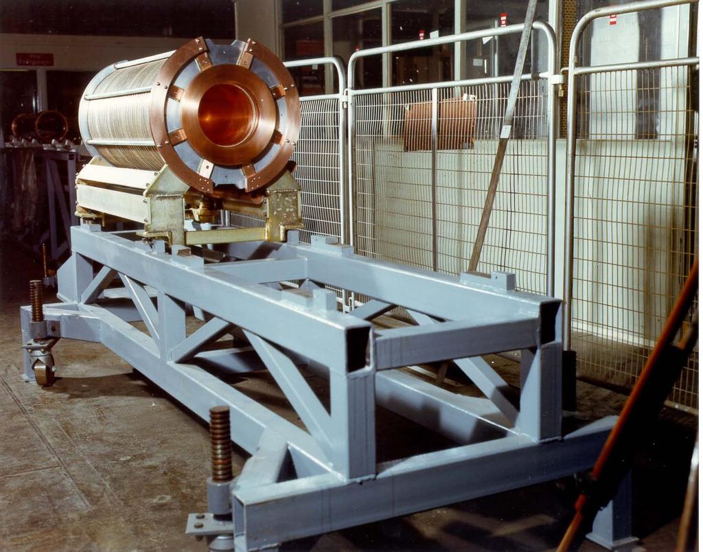
39 Nickel plated mild steel vacuum tube ready for assembly into the cavity. Provides magnetic shielding for the beam

40

41
42
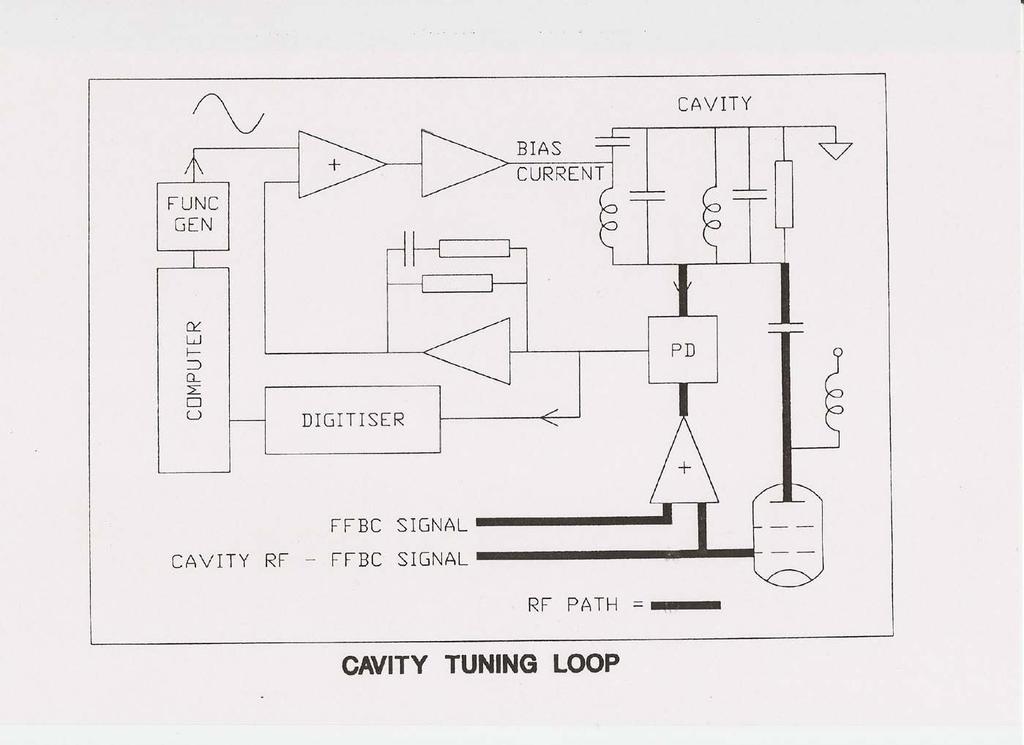
43 CAVITY TUNE SERVO CONTROL C b L C g L C g Bias current adjusted to keep cavity impedance purely resistive Typical bias currents vary from few amps to thousands of amps Minimum current must be kept high enough to cater for μ' variation
44 TUNING CONTROL Cavity bandwidth to amplitude and phase modulation is f o /2Q The capacitor C b and the two resonators form a tuned circuit for the bias system with a resonant frequency f = 1/(2π (2LC b )) The tuning control loop needs to account for both these time constants For rapid cycling FFAGs this can be a challenge The Q value of the resonators will vary with the rate of change of bias current and the gap voltage Worst case bandwidths must be catered for or dynamic control systems used
45 TUNING ERROR Phase error, due to bandwidth limitations, is given by the response to a ramped frequency input and: Where: φ o = K[t + τ(e (-t/τ) 1)] φ e steady state will be φ e = Kτ 1/(2πτ) = the tuning system bandwidth φ e = the cavity voltage phase error and: K = df/dt (πq/2f o ) f o FFAGs like PAMELA have very high df/dt = frequency at which df/dt is a maximum Methods to reduce these errors use additional digital control
46

47 Cavity equivalent circuit
48 Sum of all Cavity Gap Voltages 1RF4 Gap Volts & Anode Current Accel Volts (kv) Gap V (kv) & Ia (A) 10 5 Gap V Ia+beam Time (ms) Time (ms) Frequency Cavity Impedance Frequency (MHz) Cavity Impedance (kohms) Time (ms) Time (ms)
49 Q-Value 100 With R(L) No R(L) TRig Q Time (ms) Dynamic Q
50 Q-Value 100 With R(L) No R(L) TRig Q Frequency (MHz)
51 FNL Booster Synchrotron drift tube system (33-53 MHz) Three resonators in parallel to achieve sufficiently low inductance No decoupling capacitor. No induced RF voltage in bias winding Inner wall of the resonator is resistive and must be driven as a shorted turn by the 10 turn bias field supply
52 FNL Booster RF system equivalent circuit
 Virtual RF ground in the middle of the cavity Resonator RF voltages in anti-phase Balanced RF voltages on the figure of eight bias windings Bias")
53 No RF voltage on the bias supply CERN PS Booster Cavity (3 8.4 MHz) Virtual RF ground in the middle of the cavity Resonator RF voltages in anti-phase Balanced RF voltages on the figure of eight bias windings Bias windings give strong coupling between the two resonators Single ended or differential drive can be used
54 CERN PS Booster equivalent circuit
55 Bias field bandwidth set by f o /(2Q) and 1/(2π (2LC b )) RF voltage is carried by the bias windings Need to avoid voltage breakdown from bias conductors Need to avoid RF resonances involving the bias windings. This gets more difficult with higher numbers of turns
 RF voltage on the bias winding is made zero at the bias supply feed point by splitting the winding at the mid voltage point The two")
56 Single gap design CERN LEAR cavity ( MHz) RF voltage on the bias winding is made zero at the bias supply feed point by splitting the winding at the mid voltage point The two windings are crossed and the parallel bias field is in opposite directions in each half of the cavity
57 CERN LEAR Bias system equivalent circuit Resonance produced by L b and C b

58 The Los Alamos/TRIUMF single gap cavity (46 61 MHz) Perpendicular solenoidal bias of microwave ferrite Elaborate cuts in cavity outer to reduce eddy currents Metallic cooling plates excluded
59 Los Alamos/TRIUMF cavity equivalent circuit High bias field used for low μ and high Q Some stray field on beam axis
60 HIGH ORDER MODES First resonant mode above fundamental occurs for 180 As resonators usually less than 26 next mode at least 5 times the fundamental These modes usually well damped by ferrite losses Additional modes are most likely caused by multi-turn bias windings and co-axial coupling arms (ISIS 11 MHz) Measure, model and damp as necessary
61 SUMMARY Reviewed ferrite properties; magnetic, electric and thermal From μ' & μ" select suitable ferrites to match required frequency range of accelerating system Estimate the size and length of a resonator for a particular gap voltage Determine the cooling required to stay below Curie temperature Select a suitable cavity design Estimate the tuning system bandwidth and tuning errors Measure the ferrite properties at the right rate of change of bias and voltage to obtain Q-value and impedance
62 ISIS Fundamental RF Cavity Parameters 7 Sept 2011 ISKG wl/v (rad) 0.38 wl/v (deg) 21.7 Resonator length (m) 1.12 Mean Ferrite Power (kw) Mean resonator Ferrite Power (kw) Ferrite vol for 1 resonator (cu m) Power density (W/ml) Power mean (W/m) Power max (W/m) Power density max (W/ml) Power density max (W/cu m) Temp rise (deg C) 5.51 Original data lost following laptop disk failure some time ago No of ferrites per resonator 35 k1 4.30E-08 No of cooling disks 36 k2 3.05E+06 Length of resonator (m) 1.12 r1 (m) r2 (m) r3 (m) d1 (mm) d2 (mm) fo (Hz) fo (MHz) µ epsil x µe epsil-e v (m/s) E lmax (m) Brfmax (T) lbmax(m) Zo (ohm) wl/v (deg) L (µh) Vgap (volts pk) Vgap max (kv pk) Vol fer (cu m) C (nf)
Harald Klingbeil GSI Helmholtzzentrum für Schwerionenforschung GmbH. Contents
 CERN Accelerator School Ferrite Cavities Harald Klingbeil GSI Helmholtzzentrum für Schwerionenforschung GmbH Contents Usage of Ferrite Cavities Magnetic properties, hysteresis Simplified ferrite cavity
GLOSSARY OF TERMS FLUX DENSITY:
 ADSL: Asymmetrical Digital Subscriber Line. Technology used to transmit/receive data and audio using the pair copper telephone lines with speed up to 8 Mbps. AMBIENT TEMPERATURE: The temperature surrounding
What is an Inductor? Token Electronics Industry Co., Ltd. Version: January 16, Web:
 Version: January 16, 2017 What is an Inductor? Web: www.token.com.tw Email: rfq@token.com.tw Token Electronics Industry Co., Ltd. Taiwan: No.137, Sec. 1, Zhongxing Rd., Wugu District, New Taipei City,
Radio Frequency Electronics
 Radio Frequency Electronics Preliminaries II Guglielmo Giovanni Maria Marconi Thought off by many people as the inventor of radio Pioneer in long-distance radio communications Shared Nobel Prize in 1909
PHYSICS WORKSHEET CLASS : XII. Topic: Alternating current
 PHYSICS WORKSHEET CLASS : XII Topic: Alternating current 1. What is mean by root mean square value of alternating current? 2. Distinguish between the terms effective value and peak value of an alternating
Chapter 11. Alternating Current
 Unit-2 ECE131 BEEE Chapter 11 Alternating Current Objectives After completing this chapter, you will be able to: Describe how an AC voltage is produced with an AC generator (alternator) Define alternation,
Chapter 2. The Fundamentals of Electronics: A Review
 Chapter 2 The Fundamentals of Electronics: A Review Topics Covered 2-1: Gain, Attenuation, and Decibels 2-2: Tuned Circuits 2-3: Filters 2-4: Fourier Theory 2-1: Gain, Attenuation, and Decibels Most circuits
Properties of Inductor and Applications
 LABORATORY Experiment 3 Properties of Inductor and Applications 1. Objectives To investigate the properties of inductor for different types of magnetic material To calculate the resonant frequency of a
Chapter Moving Charges and Magnetism
 100 Chapter Moving Charges and Magnetism 1. The power factor of an AC circuit having resistance (R) and inductance (L) connected in series and an angular velocity ω is [2013] 2. [2002] zero RvB vbl/r vbl
application note Philips Magnetic Products Cable Shielding Philips Components
 application note Cable Shielding Philips Components Cable Shielding Contents Introduction 3 EMI suppression and cable shielding with ferrites 4 Ferrite selection 6 Material properties 7 Ferrite core and
K6RIA, Extra Licensing Class. Circuits & Resonance for All!
 K6RIA, Extra Licensing Class Circuits & Resonance for All! Amateur Radio Extra Class Element 4 Course Presentation ELEMENT 4 Groupings Rules & Regs Skywaves & Contesting Outer Space Comms Visuals & Video
Electromagnetic Oscillations and Currents. March 23, 2014 Chapter 30 1
 Electromagnetic Oscillations and Currents March 23, 2014 Chapter 30 1 Driven LC Circuit! The voltage V can be thought of as the projection of the vertical axis of the phasor V m representing the time-varying
Class XII Chapter 7 Alternating Current Physics
 Question 7.1: A 100 Ω resistor is connected to a 220 V, 50 Hz ac supply. (a) What is the rms value of current in the circuit? (b) What is the net power consumed over a full cycle? Resistance of the resistor,
ARNSW Balun Day. Balun construction
 ARNSW Balun Day Balun construction Typical Baluns All built from locally available components. Balun uses Most baluns are used to match the 50Ω output of a transceiver to an antenna. A centre fed dipole
(i) Determine the admittance parameters of the network of Fig 1 (f) and draw its - equivalent circuit.
 Determine the admittance parameters of the network of Fig 1 (f) and draw its - equivalent circuit.") I.E.S-(Conv.)-1995 ELECTRONICS AND TELECOMMUNICATION ENGINEERING PAPER - I Some useful data: Electron charge: 1.6 10 19 Coulomb Free space permeability: 4 10 7 H/m Free space permittivity: 8.85 pf/m Velocity
I.E.S-(Conv.)-1995 ELECTRONICS AND TELECOMMUNICATION ENGINEERING PAPER - I Some useful data: Electron charge: 1.6 10 19 Coulomb Free space permeability: 4 10 7 H/m Free space permittivity: 8.85 pf/m Velocity
Design and Construction of a150kv/300a/1µs Blumlein Pulser
 Design and Construction of a150kv/300a/1µs Blumlein Pulser J.O. ROSSI, M. UEDA and J.J. BARROSO Associated Plasma Laboratory National Institute for Space Research Av. dos Astronautas 1758, São José dos
Booster High-level RF Frequency Tracking Improvement Via the Bias-Curve Optimization
 FERMILAB-TM-227-AD Booster High-level RF Frequency Tracking Improvement Via the Bias-Curve Optimization Xi Yang Fermi National Accelerator Laboratory Box 5, Batavia IL 651 Abstract It is important to improve
Iron Powder Cores for High Q Inductors By: Jim Cox - Micrometals, Inc.
 HOME APPLICATION NOTES Iron Powder Cores for High Q Inductors By: Jim Cox - Micrometals, Inc. SUBJECT: A brief overview will be given of the development of carbonyl iron powders. We will show how the magnetic
Iron Powder Core Selection For RF Power Applications. Jim Cox Micrometals, Inc. Anaheim, CA
 HOME APPLICATION NOTES Iron Powder Core Selection For RF Power Applications Jim Cox Micrometals, Inc. Anaheim, CA Purpose: The purpose of this article is to present new information that will allow the
Lab 2 Radio-frequency Coils and Construction
 ab 2 Radio-frequency Coils and Construction Background: In order for an MR transmitter/receiver coil to work efficiently to excite and detect the precession of magnetization, the coil must be tuned to
Inductors & Resonance
 Inductors & Resonance The Inductor This figure shows a conductor carrying a current. A magnetic field is set up around the conductor as concentric circles. If a coil of wire has a current flowing through
Γ L = Γ S =
 TOPIC: Microwave Circuits Q.1 Determine the S parameters of two port network consisting of a series resistance R terminated at its input and output ports by the characteristic impedance Zo. Q.2 Input matching
Generation of Sub-nanosecond Pulses
 Chapter - 6 Generation of Sub-nanosecond Pulses 6.1 Introduction principle of peaking circuit In certain applications like high power microwaves (HPM), pulsed laser drivers, etc., very fast rise times
Exercise 9: inductor-resistor-capacitor (LRC) circuits
 circuits") Exercise 9: inductor-resistor-capacitor (LRC) circuits Purpose: to study the relationship of the phase and resonance on capacitor and inductor reactance in a circuit driven by an AC signal. Introduction
Exercise 9: inductor-resistor-capacitor (LRC) circuits Purpose: to study the relationship of the phase and resonance on capacitor and inductor reactance in a circuit driven by an AC signal. Introduction
Diagnostics I M. Minty DESY
 Diagnostics I M. Minty DESY Introduction Beam Charge / Intensity Beam Position Summary Introduction Transverse Beam Emittance Longitudinal Beam Emittance Summary Diagnostics I Diagnostics II Synchrotron
BEST BMET CBET STUDY GUIDE MODULE ONE
 BEST BMET CBET STUDY GUIDE MODULE ONE 1 OCTOBER, 2008 1. The phase relation for pure capacitance is a. current leads voltage by 90 degrees b. current leads voltage by 180 degrees c. current lags voltage
Inductor Glossary. Token Electronics Industry Co., Ltd. Version: January 16, Web:
 Version: January 16, 2017 Inductor Glossary Web: www.token.com.tw Email: rfq@token.com.tw Token Electronics Industry Co., Ltd. Taiwan: No.137, Sec. 1, Zhongxing Rd., Wugu District, New Taipei City, Taiwan,
Alternating Current Circuits and Electromagnetic Waves
 hapter Alternating urrent ircuits and Electromagnetic Wes Quick Quizzes. (a, (c. The erage power is proportional to the current which is non-zero even though the erage current is zero. (a is only valid
Radio Frequency Electronics
 Radio Frequency Electronics Frederick Emmons Terman Transformers Masters degree from Stanford and Ph.D. from MIT Later a professor at Stanford His students include William Hewlett and David Packard Wrote
An induced emf is the negative of a changing magnetic field. Similarly, a self-induced emf would be found by
 This is a study guide for Exam 4. You are expected to understand and be able to answer mathematical questions on the following topics. Chapter 32 Self-Induction and Induction While a battery creates an
AC Circuits INTRODUCTION DISCUSSION OF PRINCIPLES. Resistance in an AC Circuit
 AC Circuits INTRODUCTION The study of alternating current 1 (AC) in physics is very important as it has practical applications in our daily lives. As the name implies, the current and voltage change directions
VETRI VINAYAHA COLLEGE OF ENGINEERING AND TECHNOLOGY
 VETRI VINAYAHA COLLEGE OF ENGINEERING AND TECHNOLOGY DEPARTMENT OF ELECTRICAL AND ELECTRONICS ENGINEERING I-YEAR/II-SEMESTER- EEE&ECE EE6201- CIRCUIT THEORY Two Marks with Answers PREPARED BY: Mr.A.Thirukkumaran,
Waveforms for Stimulating Magnetic Cores
 Waveforms for Stimulating Magnetic Cores My assigned topic is test waveforms for magnetic cores, but I'm going to provide a little background, which touches on topics covered by other presenters here:
PHYS 1441 Section 001 Lecture #22 Wednesday, Nov. 29, 2017
 PHYS 1441 Section 001 Lecture #22 Chapter 29:EM Induction & Faraday s Law Transformer Electric Field Due to Changing Magnetic Flux Chapter 30: Inductance Mutual and Self Inductance Energy Stored in Magnetic
1. What is the unit of electromotive force? (a) volt (b) ampere (c) watt (d) ohm. 2. The resonant frequency of a tuned (LRC) circuit is given by
 volt (b) ampere (c) watt (d) ohm. 2. The resonant frequency of a tuned (LRC) circuit is given by") Department of Examinations, Sri Lanka EXAMINATION FOR THE AMATEUR RADIO OPERATORS CERTIFICATE OF PROFICIENCY ISSUED BY THE DIRECTOR GENERAL OF TELECOMMUNICATIONS, SRI LANKA 2004 (NOVICE CLASS) Basic Electricity,
Department of Examinations, Sri Lanka EXAMINATION FOR THE AMATEUR RADIO OPERATORS CERTIFICATE OF PROFICIENCY ISSUED BY THE DIRECTOR GENERAL OF TELECOMMUNICATIONS, SRI LANKA 2004 (NOVICE CLASS) Basic Electricity,
AC Measurement of Magnetic Susceptibility
 AC Measurement of Magnetic Susceptibility Ferromagnetic materials such as iron, cobalt and nickel are made up of microscopic domains in which the magnetization of each domain has a well defined orientation.
Oscillators. An oscillator may be described as a source of alternating voltage. It is different than amplifier.
 Oscillators An oscillator may be described as a source of alternating voltage. It is different than amplifier. An amplifier delivers an output signal whose waveform corresponds to the input signal but
2/18/ Transmission Lines and Waveguides 1/3. and Waveguides. Transmission Line A two conductor structure that can support a TEM wave.
 2/18/2009 3 Transmission Lines and Waveguides 1/3 Chapter 3 Transmission Lines and Waveguides First, some definitions: Transmission Line A two conductor structure that can support a TEM wave. Waveguide
A Fresh Look at Design of Buck and Boost inductors for SMPS Converters
 A Fresh Look at Design of Buck and Boost inductors for SMPS Converters Authors: Weyman Lundquist, Carl Castro, both employees of West Coast Magnetics. Inductors are a critical component in buck and boost
A Low-Loss VHF/UHF Diplexer
 A Low-Loss / Diplexer Why use two lengths of expensive feed line when one will do? This hy box lets you use one feed line for both energy, simultaneously! By Pavel Zanek, OK1DNZ Do you need to operate
Switching Power Supplies
 Switching Power Supplies Chuck Clark AF8Z WWW..ORG 1 Regulated Power Supply Basics WWW..ORG 2 Topics Linear Supplies Switching Supplies Components WWW..ORG 3 Why switching supplies Smaller Lighter More
EC Transmission Lines And Waveguides
 EC6503 - Transmission Lines And Waveguides UNIT I - TRANSMISSION LINE THEORY A line of cascaded T sections & Transmission lines - General Solution, Physical Significance of the Equations 1. Define Characteristic
JEFFERSON COLLEGE COURSE SYLLABUS ETC104 AC CIRCUITS. 5 Credit Hours. Prepared by: Ronald S. Krive. Revised Date: October 2007 by Dennis Eimer
 JEFFERSON COLLEGE COURSE SYLLABUS ETC104 AC CIRCUITS 5 Credit Hours Prepared by: Ronald S. Krive Revised Date: October 2007 by Dennis Eimer Division of Technology Dr. John Keck, Dean Ms. Brenda Russell,
Design of Integrated LC Filter Using Multilayer Flexible Ferrite Sheets S. Coulibaly 1, G. Loum 1, K.A. Diby 2
 IOSR Journal of Electrical and Electronics Engineering (IOSR-JEEE) e-issn: 2278-1676,p-ISSN: 232-3331, Volume 1, Issue 6 Ver. I (Nov Dec. 215), PP 35-43 www.iosrjournals.org Design of Integrated LC Filter
VE7CNF - 630m Antenna Matching Measurements Using an Oscilloscope
 VE7CNF - 630m Antenna Matching Measurements Using an Oscilloscope Toby Haynes October, 2016 1 Contents VE7CNF - 630m Antenna Matching Measurements Using an Oscilloscope... 1 Introduction... 1 References...
STABILITY CONSIDERATIONS
 Abstract The simple theory describing the stability of an RF system with beam will be recalled together with its application to the LEP case. The so-called nd Robinson stability limit can be pushed by
RESONANT CAVITIES FOR DUPLEX FILTERS IN VHF REPEATERS: ANALISYS, IMPLEMENTATION, AND TESTING
 RESONANT CAVITIES FOR DUPLEX FILTERS IN VHF REPEATERS: ANALISYS, IMPLEMENTATION, AND TESTING Gheorghe SAUCIUC Tehnical University Gheorghe Asachi of Iasi - Faculty of Electronics, Telecommunication and
Main Injector Cavity Simulation and Optimization for Project X
 Main Injector Cavity Simulation and Optimization for Project X Liling Xiao Advanced Computations Group Beam Physics Department Accelerator Research Division Status Meeting, April 7, 2011 Outline Background
V I S H A y I n T E R T E C H n O l O G y, I n C. In D u C T O R S In S T R u C TIO n A l INDuCtOR 101 Gu ID E w w w. v i s h a y.
 VISHAY INTERTECHNOLOGY, INC. INDUCTORS INDUCTOR 101 instructional Guide www.vishay.com Inductor 101 Inductor A passive component designed to resist changes in current. Inductors are often referred to as
The Principle V(SWR) The Result. Mirror, Mirror, Darkly, Darkly
 The Result. Mirror, Mirror, Darkly, Darkly") The Principle V(SWR) The Result Mirror, Mirror, Darkly, Darkly 1 Question time!! What do you think VSWR (SWR) mean to you? What does one mean by a transmission line? Coaxial line Waveguide Water pipe Tunnel
The Principle V(SWR) The Result Mirror, Mirror, Darkly, Darkly 1 Question time!! What do you think VSWR (SWR) mean to you? What does one mean by a transmission line? Coaxial line Waveguide Water pipe Tunnel
EC6503 Transmission Lines and WaveguidesV Semester Question Bank
 UNIT I TRANSMISSION LINE THEORY A line of cascaded T sections & Transmission lines General Solution, Physicasignificance of the equations 1. Derive the two useful forms of equations for voltage and current
RF Power Amplifier (RFPA) Designing a 'Output Tank Circuit'
 Designing a 'Output Tank Circuit'") RF Power Amplifier (RFPA) Designing a 'Output Tank Circuit' By Larry E. Gugle K4RFE, RF Design, Manufacture, Test & Service Engineer (Retired) Figure-1 Output 'Tank' Circuit Network in Low-Pass Filter
RF Power Amplifier (RFPA) Designing a 'Output Tank Circuit' By Larry E. Gugle K4RFE, RF Design, Manufacture, Test & Service Engineer (Retired) Figure-1 Output 'Tank' Circuit Network in Low-Pass Filter
HOME APPLICATION NOTES
 HOME APPLICATION NOTES INDUCTOR DESIGNS FOR HIGH FREQUENCIES Powdered Iron "Flux Paths" can Eliminate Eddy Current 'Gap Effect' Winding Losses INTRODUCTION by Bruce Carsten for: MICROMETALS, Inc. There
Exam 3 Solutions. ! r, the ratio is ( N ) ( ) ( )( ) 2. PHY2054 Spring Prof. Pradeep Kumar Prof. Paul Avery Prof. Yoonseok Lee Mar.
 ( ) ( )( ) 2. PHY2054 Spring Prof. Pradeep Kumar Prof. Paul Avery Prof. Yoonseok Lee Mar.") PHY054 Spring 009 Prof. Pradeep Kumar Prof. Paul Avery Prof. Yoonseok Lee Mar. 7, 009 Exam 3 Solutions 1. Two coils (A and B) made out of the same wire are in a uniform magnetic field with the coil axes
PHY054 Spring 009 Prof. Pradeep Kumar Prof. Paul Avery Prof. Yoonseok Lee Mar. 7, 009 Exam 3 Solutions 1. Two coils (A and B) made out of the same wire are in a uniform magnetic field with the coil axes
ELECTROMAGNETIC INDUCTION AND ALTERNATING CURRENT (Assignment)
") ELECTROMAGNETIC INDUCTION AND ALTERNATING CURRENT (Assignment) 1. In an A.C. circuit A ; the current leads the voltage by 30 0 and in circuit B, the current lags behind the voltage by 30 0. What is the
ELECTROMAGNETIC INDUCTION AND ALTERNATING CURRENT (Assignment) 1. In an A.C. circuit A ; the current leads the voltage by 30 0 and in circuit B, the current lags behind the voltage by 30 0. What is the
Introduction. Inductors in AC Circuits.
 Module 3 AC Theory What you ll learn in Module 3. Section 3.1 Electromagnetic Induction. Magnetic Fields around Conductors. The Solenoid. Section 3.2 Inductance & Back e.m.f. The Unit of Inductance. Factors
3. What is hysteresis loss? Also mention a method to minimize the loss. (N-11, N-12)
") DHANALAKSHMI COLLEGE OF ENGINEERING, CHENNAI DEPARTMENT OF ELECTRICAL AND ELECTRONICS ENGINEERING EE 6401 ELECTRICAL MACHINES I UNIT I : MAGNETIC CIRCUITS AND MAGNETIC MATERIALS Part A (2 Marks) 1. List
DHANALAKSHMI COLLEGE OF ENGINEERING, CHENNAI DEPARTMENT OF ELECTRICAL AND ELECTRONICS ENGINEERING EE 6401 ELECTRICAL MACHINES I UNIT I : MAGNETIC CIRCUITS AND MAGNETIC MATERIALS Part A (2 Marks) 1. List
LOI Progress Report -- Summary of Experiment in January
 LOI Progress Report -- Summary of Experiment in January 2010 -- LOI-7 February 18, 2010 1. Introduction Following the previous experiments in October, 2009, a new method to improve the RF waveform distortions
Aligarh College of Engineering & Technology (College Code: 109) Affiliated to UPTU, Approved by AICTE Electrical Engg.
 Affiliated to UPTU, Approved by AICTE Electrical Engg.") Aligarh College of Engineering & Technology (College Code: 19) Electrical Engg. (EE-11/21) Unit-I DC Network Theory 1. Distinguish the following terms: (a) Active and passive elements (b) Linearity and
Aligarh College of Engineering & Technology (College Code: 19) Electrical Engg. (EE-11/21) Unit-I DC Network Theory 1. Distinguish the following terms: (a) Active and passive elements (b) Linearity and
LEP RLC Circuit
 RLC Circuit LEP Related topics Kirchhoff s laws, series and parallel tuned circuit, resistance, capacitance, inductance, phase displacement, Q-factor, band-width, loss resistance, damping Principle The
The design of Ruthroff broadband voltage transformers M. Ehrenfried G8JNJ
 The design of Ruthroff broadband voltage transformers M. Ehrenfried G8JNJ Introduction I started investigating balun construction as a result of various observations I made whilst building HF antennas.
Walchand Institute of Technology. Basic Electrical and Electronics Engineering. Transformer
 Walchand Institute of Technology Basic Electrical and Electronics Engineering Transformer 1. What is transformer? explain working principle of transformer. Electrical power transformer is a static device
CHAPTER 6 BOOSTER RF SYSTEMS
 CHAPTER 6 BOOSTER RF SYSTEMS 6.1 NEW PSB RF CAVITIES H = 1 (0.6 1.8 MHz) The addition of cavities accelerating on RF harmonic h = 1 and supplemented with a h = 2 system, contributed to the reduction of
Alternating Current Study Guide. Preface. This module is DIFFICULT.
 Preface This module is DIFFICULT. This material will take more effort to understand and more effort to pass than tests from previous modules. This is on par with a college-level electrical engineering
Summary LOI Developments
 The 8th Collaboration Meeting on the 2nd Harmonic RF System July 4, 2003, ISIS Summary LOI Developments 1996 through 2003 1. Introduction why the Low Output Impedance? 2. History of the scheme (1) cathode
AP Physics C. Alternating Current. Chapter Problems. Sources of Alternating EMF
 AP Physics C Alternating Current Chapter Problems Sources of Alternating EMF 1. A 10 cm diameter loop of wire is oriented perpendicular to a 2.5 T magnetic field. What is the magnetic flux through the
PHYS 1444 Section 501 Lecture #20
 PHYS 1444 Section 501 Lecture #0 Monday, Apr. 17, 006 Transformer Generalized Faraday s Law Inductance Mutual Inductance Self Inductance Inductor Energy Stored in the Magnetic Field 1 Announcements Quiz
Electrical Theory 2 Lessons for Fall Semester:
 Electrical Theory 2 Lessons for Fall Semester: Lesson 1 Magnetism Lesson 2 Introduction to AC Theory Lesson 3 Lesson 4 Capacitance and Capacitive Reactance Lesson 5 Impedance and AC Circuits Lesson 6 AC
R. W. Erickson. Department of Electrical, Computer, and Energy Engineering University of Colorado, Boulder
 R. W. Erickson Department of Electrical, Computer, and Energy Engineering University of Colorado, Boulder 13.2.3 Leakage inductances + v 1 (t) i 1 (t) Φ l1 Φ M Φ l2 i 2 (t) + v 2 (t) Φ l1 Φ l2 i 1 (t)
Design Considerations
 Design Considerations Ferrite toroids provide an often convenient and very effective shape for many wide band, pulse and power transformers and inductors. The continuous magnetic path yields the highest
1. (a) Determine the value of Resistance R and current in each branch when the total current taken by the curcuit in figure 1a is 6 Amps.
 Determine the value of Resistance R and current in each branch when the total current taken by the curcuit in figure 1a is 6 Amps.") Code No: 07A3EC01 Set No. 1 II B.Tech I Semester Regular Examinations, November 2008 ELECTRICAL AND ELECTRONICS ENGINEERING ( Common to Civil Engineering, Mechanical Engineering, Mechatronics, Production
Code No: 07A3EC01 Set No. 1 II B.Tech I Semester Regular Examinations, November 2008 ELECTRICAL AND ELECTRONICS ENGINEERING ( Common to Civil Engineering, Mechanical Engineering, Mechatronics, Production
Design of a Regenerative Receiver for the Short-Wave Bands A Tutorial and Design Guide for Experimental Work. Part I
 Design of a Regenerative Receiver for the Short-Wave Bands A Tutorial and Design Guide for Experimental Work Part I Ramón Vargas Patrón rvargas@inictel-uni.edu.pe INICTEL-UNI Regenerative Receivers remain
Study of Inductive and Capacitive Reactance and RLC Resonance
 Objective Study of Inductive and Capacitive Reactance and RLC Resonance To understand how the reactance of inductors and capacitors change with frequency, and how the two can cancel each other to leave
The below identified patent application is available for licensing. Requests for information should be addressed to:
 DEPARTMENT OF THE NAVY OFFICE OF COUNSEL NAVAL UNDERSEA WARFARE CENTER DIVISION 1176 HOWELL STREET NEWPORT Rl 02841-1708 IN REPLY REFER TO Attorney Docket No. 300104 25 May 2017 The below identified patent
Components, those bits and pieces which make up
 COMPONENTS and Systems CHAPTER 1 Components, those bits and pieces which make up a radio frequency (RF) circuit, seem at times to be taken for granted. A capacitor is, after all, a capacitor isn t it?
Electrical Design Process
 Electrical Design Process Jason Varnell Lead Design Engineer Jason.Varnell@spx.com SPX Transformer Solutions, Inc. September 26, 2018 Agenda 1. Bid Design Process Parameters Affecting Bid Design 2. Final
Glossary of Common Magnetic Terms
 Glossary of Common Magnetic Terms Copyright by Magnelab, Inc. 2009 Air Core A term used when no ferromagnetic core is used to obtain the required magnetic characteristics of a given coil. (see Core) Ampere
15. the power factor of an a.c circuit is.5 what will be the phase difference between voltage and current in this
 1 1. In a series LCR circuit the voltage across inductor, a capacitor and a resistor are 30 V, 30 V and 60 V respectively. What is the phase difference between applied voltage and current in the circuit?
Lecture 4. Maximum Transfer of Power. The Purpose of Matching. Lecture 4 RF Amplifier Design. Johan Wernehag Electrical and Information Technology
 Johan Wernehag, EIT Lecture 4 RF Amplifier Design Johan Wernehag Electrical and Information Technology Design of Matching Networks Various Purposes of Matching Voltage-, Current- and Power Matching Design
Loop and Slot Antennas
 Loop and Slot Antennas Prof. Girish Kumar Electrical Engineering Department, IIT Bombay gkumar@ee.iitb.ac.in (022) 2576 7436 Loop Antenna Loop antennas can have circular, rectangular, triangular or any
Generator Power [kw]
![Generator Power [kw]](/thumbs/92/108462849.jpg "Generator Power [kw]") PW3-25-SA/80 PW3-50-SA/80 PW3-100-SA/80 0 25 50 75 100 Generator Power [kw] 100-SA/80 Generator Overall Dimensions 25-SA/80 and 50-SA/80 Generator PWH-22 PWH-20 PWH-24 Capacity Output Power Dimensions
PW3-25-SA/80 PW3-50-SA/80 PW3-100-SA/80 0 25 50 75 100 Generator Power [kw] 100-SA/80 Generator Overall Dimensions 25-SA/80 and 50-SA/80 Generator PWH-22 PWH-20 PWH-24 Capacity Output Power Dimensions
CHAPTER IV DESIGN OF TESLA COIL
 CHAPTER IV DESIGN OF TESLA COIL In this chapter, the design and calculation regarding spark gap tesla coil is shown as well as the design for the voltage regulator and the zero voltage switching driver
Look over Chapter 31 sections 1-4, 6, 8, 9, 10, 11 Examples 1-8. Look over Chapter 21 sections Examples PHYS 2212 PHYS 1112
 PHYS 2212 Look over Chapter 31 sections 1-4, 6, 8, 9, 10, 11 Examples 1-8 PHYS 1112 Look over Chapter 21 sections 11-14 Examples 16-18 Good Things To Know 1) How AC generators work. 2) How to find the
The G4EGQ RAE Course Lesson 4A AC theory
 AC. CIRCUITS This lesson introduces inductors into our AC. circuit. We then look at the result of having various combinations of capacitance, inductance and resistance in the same circuit. This leads us
ALTERNATING CURRENT. Lesson-1. Alternating Current and Voltage
 esson- ATENATING UENT Alternating urrent and oltage An alternating current or voltage is that variation of current or voltage respectively whose magnitude and direction vary periodically and continuously
EE301 ELECTRONIC CIRCUITS CHAPTER 2 : OSCILLATORS. Lecturer : Engr. Muhammad Muizz Bin Mohd Nawawi
 EE301 ELECTRONIC CIRCUITS CHAPTER 2 : OSCILLATORS Lecturer : Engr. Muhammad Muizz Bin Mohd Nawawi 2.1 INTRODUCTION An electronic circuit which is designed to generate a periodic waveform continuously at
Use of inductive heating for superconducting magnet protection*
 PSFC/JA-11-26 Use of inductive heating for superconducting magnet protection* L. Bromberg, J. V. Minervini, J.H. Schultz, T. Antaya and L. Myatt** MIT Plasma Science and Fusion Center November 4, 2011
Exercise 1: Series Resonant Circuits
 Series Resonance AC 2 Fundamentals Exercise 1: Series Resonant Circuits EXERCISE OBJECTIVE When you have completed this exercise, you will be able to compute the resonant frequency, total current, and
1.5 GHz Cavity design for the Clic Damping Ring and as Active Third Harmonic cavity for ALBA.
 1 1.5 GHz Cavity design for the Clic Damping Ring and as Active Third Harmonic cavity for ALBA. Beatriz Bravo Overview 2 1.Introduction 2.Active operation 3.Electromagnetic design 4.Mechanical design Introduction
Line Frequency Transformer
 Line Frequency Transformer For frequencies of 50/60 Hz, specify a Frequency Transformer. Line Line Frequency Transformers are customized to meet customer requirements, and are available in various ratings.
Basics of Accelerator Science and Technology at CERN. Power supplies for Particle accelerators. Jean-Paul Burnet
 Basics of Accelerator Science and Technology at CERN Power supplies for Particle accelerators Jean-Paul Burnet 2 Definition Basic electricity The loads The circuits The power supply specification Power
14 Sept 2006 Page 1 of 11 TRF7960 RFID Reader & Antenna Circuits. 1.) Introduction
 Introduction") 14 Sept 2006 Page 1 of 11 TRF7960 RFID Reader & Antenna Circuits 1.) Introduction This paper describes the design method for determining an antenna matching circuit together with Tx and Rx interface circuits
14 Sept 2006 Page 1 of 11 TRF7960 RFID Reader & Antenna Circuits 1.) Introduction This paper describes the design method for determining an antenna matching circuit together with Tx and Rx interface circuits
Lab 1: Basic RL and RC DC Circuits
 Name- Surname: ID: Department: Lab 1: Basic RL and RC DC Circuits Objective In this exercise, the DC steady state response of simple RL and RC circuits is examined. The transient behavior of RC circuits
1. If the flux associated with a coil varies at the rate of 1 weber/min,the induced emf is
 1. f the flux associated with a coil varies at the rate of 1 weber/min,the induced emf is 1 1. 1V 2. V 60 3. 60V 4. Zero 2. Lenz s law is the consequence of the law of conservation of 1. Charge 2. Mass
EC TRANSMISSION LINES AND WAVEGUIDES TRANSMISSION LINES AND WAVEGUIDES
 TRANSMISSION LINES AND WAVEGUIDES UNIT I - TRANSMISSION LINE THEORY 1. Define Characteristic Impedance [M/J 2006, N/D 2006] Characteristic impedance is defined as the impedance of a transmission line measured
Non-Ideal Behavior of Components
 Non-Ideal Behavior of Components Todd H. Hubing Dept. of Electrical and Computer Engineering Clemson, University Clemson, SC 29634 USA email: hubing@clemson.edu Telephone: 1-864-656-7219 Circuit Schematics
Table of Contents. Introduction...2 Conductors and Insulators...3 Current, Voltage, and Resistance...6
 Table of Contents Introduction...2 Conductors and Insulators...3 Current, Voltage, and Resistance...6 Ohm s Law... 11 DC Circuits... 13 Magnetism...20 Alternating Current...23 Inductance and Capacitance...30
Solving Electromagnetic Interference (EMI) with Ferrites
 with Ferrites") Solving Electromagnetic Interference (EMI) with Ferrites What are ferrites? How do ferrites help Suppress EMI? How to chose proper ferrite and component Material Characteristics Material and Core Selection
Solving Electromagnetic Interference (EMI) with Ferrites What are ferrites? How do ferrites help Suppress EMI? How to chose proper ferrite and component Material Characteristics Material and Core Selection
BE. Electronic and Computer Engineering Final Year Project Report
 BE. Electronic and Computer Engineering Final Year Project Report Title: Development of electrical models for inductive coils used in wireless power systems Paul Burke 09453806 3 rd April 2013 Supervisor:
TUNED AMPLIFIERS 5.1 Introduction: Coil Losses:
 TUNED AMPLIFIERS 5.1 Introduction: To amplify the selective range of frequencies, the resistive load R C is replaced by a tuned circuit. The tuned circuit is capable of amplifying a signal over a narrow