Basics of Accelerator Science and Technology at CERN. Power supplies for Particle accelerators. Jean-Paul Burnet
|
|
|
- Claire Poole
- 6 years ago
- Views:
Transcription
1
2 Basics of Accelerator Science and Technology at CERN Power supplies for Particle accelerators Jean-Paul Burnet 2
3 Definition Basic electricity The loads The circuits The power supply specification Power electronics, how does it works? Examples of power supplies and applications Energy saving Power supply control Summary 3


, motor drives,")
4 Definition Wikipedia: A power supply is a device that supplies electric energy to an electrical load. Power supplies are everywhere: computer, electronics, inside any modern electrical equipment (washing machine, ), motor drives, Electricity provider Power supply Load 4


5 Definition Where can we find power supplies in a particle accelerator? Everywhere! Everything is powered by electricity! This presentation covers the magnet power supplies which are specifics for particle accelerators : Power supply or power converter? US labs use magnet power supply CERN accelerators use power converter CERN experiments use power supply 5


6 Electrical power Electricity is mainly produced by rotating machines, generating alternative voltage. The accelerator magnets need a current. 400kV, 225kV, 90kV 63kV, 20kV 20kV, 6kV 400V Alternative voltage current 6


7 Power supply functions The tasks of a power supply are to process and control the flow of electric energy by supplying voltage and current in a form that is optimally suited for user loads. Energy source Application Control from CCC 7
8 Basic electricity An electric current is a flow of electric charge. In electric circuits, this charge is often carried by moving electrons in a wire. Voltage is the difference in electric potential energy between two points per unit electric charge. The voltage between two points is equal to the work done per unit of charge against a static electric field to move the test charge between two points and is measured in units of volts (a joule per coulomb). Electric Power (Watt) = Voltage (Volt) * Current (Ampere) Energy (Joule) = Power (Watt) * time (second) Matter: - Conductor = electrons flow easily. Low resistance. - Semiconductor = electrons can be made to flow under certain circumstances. - Insulator = electrons flow with great difficulty. High resistance. V(t) 8
 dt I(t) V(t) C = capacitance in Farad E c = Stored energy Difficult to change the voltage E C = 1 C V2 2")
9 Resistor: V t = R I(t) I(t) V(t) R = resistance in ohm Basic electricity current is proportional to voltage Inductor: V(t) = L di(t) dt I(t) V(t) L = inductance in Henry E L = Stored energy Difficult to change the current E L = 1 L I2 2 Capacitor I t = C dv(t) dt I(t) V(t) C = capacitance in Farad E c = Stored energy Difficult to change the voltage E C = 1 C V2 2 9

10 What are the main loads? The main loads of a particle accelerator are the magnets and the radiofrequency systems. It is also the devices which control the beams. 10


11 Are the magnet power supplies critical? In a synchrotron, the beam energy is proportional to the magnetic field of the dipole magnets. The magnet field is generated by the current circulating in the magnet coils. Magnet current Magnetic field in the air gap LHC vistar : Beam Energy = Dipole Current The magnet power supplies control the beam optics. 11


12 First step, identify the load Before any design of power supplies, the first step is to write a functional specification which describes the powering of the accelerator and the performance required by the power supplies. Many technical points have to be clarified to define all the power supply parameters. What do we need for a new particle accelerator like ELENA? ELENA: Extra Low Energy Antiproton Ring 12


13 The loads: magnets The magnet families are : Dipole: Bend the beam Quadrupole: focus the beam Sextupole: correct chromaticity Octupole: Landau damping Skew: coupling horizontal & vertical betatron oscillations 13


14 The loads, special magnets For beam transfer, special magnets are needed. The families are : Electrostatic septum Septum magnet Kicker Magnet Rise time # 10ns-1µs Kicker generators are very special and generally handled by kicker people. 14


15 The loads, RF amplifiers For the radio frequency system, the RF power comes through RF power amplifiers. The families of RF power amplifiers are : Solid state amplifier, Low power, 100V, 1 100kW Will be present with the new SPS RF Tetrode, Medium power, 10kV, 100kW Present in PS, SPS IOT, Medium power, 20-50kV, kW Present in SPS Klystron, High power RF, kV, 1-150MW Present in LINAC4, LHC 15
16 Circuit layout, how many power supplies? The magnets can be powered individually or in series. Individually: - increase flexibility of beam optics - B-field can be different depending of the cycles (hysteresis) - Global cost is higher, more cables, more power supplies - Needed when the voltage goes too high (>10kV magnet class) - Needed when the energy stored is too big (superconducting magnets) Series connected: - B-field identical - Rigid optic - Need trim power supplies to act locally - Global cost reduced, less cables, less power supplies but bigger in power rating - 16

17 Magnet in series To get the same B-field in a family of magnets as requested by accelerator physicists, the classical solution is to put all the magnets in series. Generally done with dipole and quadrupole. Example of SPS quadrupole Lead to high power system for dipole and quadrupole, up to 120MW!!! 17
 for each users (corresponding to a Fodo cell). Example, SESAME cell.")
18 For synchrotron source lights, the quadrupole are generally individually powered to adjust the beam size (beta function) for each users (corresponding to a Fodo cell). Example, SESAME cell. Individual powered magnet ±200A 18


19 Splitting the magnet circuit When the power is becoming too high, the circuits have to be split. First time with LHC in 8 sectors. All magnet families cut in 8. Tracking between sector! 1.2 GJ stored energy in dipole circuit per sector! Powering Sector: 154 dipole magnets total length of 2.9 km 19


20 Power supply specification The way that the magnets will be operated has to be defined from the beginning. - Type of control: Current control - Maximum minimum current - Complete cycle - Injection current - Maximum di/dt, ramp-up - Maximum flat top current - Maximum di/dt, ramp-down - Return current - Cycle time - Degauss cycle / pre-cycle - Standby mode 20

21 Power supply types versus magnet cycles 21


22 Origin of power electronics Power electronics is the application of solid-state electronics for the control and conversion of electric power. Power electronics started with the development of mercury arc rectifier. Invented by Peter Cooper Hewitt in 1902, the mercury arc rectifier was used to convert alternating current (AC) into direct current (). mercury arc rectifier


23 Middle age power electronics Vacuum tube or transistor used as a variable resistor (linear regulator). Vacuum tube or valve transistor
.")
24 Hippie power electronics Thyristor (1956): once it has been switched on by the gate terminal, the device remains latched in the on-state (i.e. does not need a continuous supply of gate current to remain in the on state), providing the anode current has exceeded the latching current (I L ). As long as the anode remains positively biased, it cannot be switched off until the anode current falls below the holding current (I H ). Thyristor Blocked Thyristor turn ON Thyristor turn OFF At zero current Thyristor Turn ON possible when positive voltage 24


25 Modern power electronics Use semiconductors as switches ON OFF states only Switch-mode power supply A square voltage waveform is generated by the switch. The energy transferred to the load is controlled by modulating the duty cycle D. D is the fraction of one period in which the switch is ON. Transistor, MOSFET, IGBT 1980 until now 25
26 Basic principle Resistive load Inductive load V Rl = DT T V s V Rl = D V s 1 T = switching frequency I D = Duty cycle Rl = DT T Vs R L I Rl = D Vs R L 26

27 Simple buck converter The basic principle is to command a switch to control the energy transfer to a load. Example of a BUCK converter: V o = DT T V s V o = D V s The voltage applied to the load can be changed by playing with the duty cycle. 27


28 Topologies Many topologies exist to build a switch-mode power supply and new topologies appear every years! Flyback Full bridge LLC resonant Multilevel 28

29 Switching devices Nowadays, the main power semiconductors are: - Diode - MOSFET - IGBT - Thyristor GTO The most popular is the IGBT IGBT IGBT 29


30 What is an IGBT? IGBT, the most popular device The IGBT combines the simple gate-drive characteristics of the MOSFETs with the high-current and low-saturation-voltage capability of bipolar transistors. The main different with thyristor is the ability to control its turn ON and turn OFF. Many topologies can be built using IGBT. Largely produced since A 3kA 10A 1kA 30
 is challenging!")

31 IGBT Real IGBT turn-on and turn-off: Very fast di/dt, dv/dt => generate electrical noise Electromagnetic compatibility (EMC) is challenging! Switching losses => thermal limitation Switching losses The switching frequency depends on: - The turn-on and turn-off time of the switch - The maximum losses dissipated by the switch Typical switching frequency depending on the power rating: 1kW range 100kHz 100kW range 10kHz 1MW range 1kHz 31


32 IGBT IGBT dies Inside a Module IGBT dies exist only from 25A to 150A for 1.2kV and 1.7kV. IGBT have good thermal and electrical coefficients which also to place them in parallel. IGBT modules have many dies in parallel to increase their current rating. 32
33 The magnets need current. Topologies based on IGBT The magnet power supplies are always AC/. The topologies are build with many stages of conversion. The magnets need also a galvanic isolation from the mains. cases with 50Hz transformer AC mains AC Magnets 33
34 Switch-mode power supply Vmagnet Example: PS converter: PR.WFNI, ±250A/±600V Imagnet 50Hz AC/ stage 6kHz / stage 34


35 35

:")
 Limitation due to eddy")


36 Transformer technologies Two technologies are used for power transformers: laminated magnetic core (like magnet): 50Hz technology High field (1.8T) Limitation due to eddy current Low power density High power range Ferrite core (like kicker): khz technology Low field (0.3T) Nonconductive magnetic material, very low eddy current High power density Low power range (<100kW) 36
37 Topologies with HF transformer In this case, it is multi-stages converter with high-frequency inverters AC mains AC AC AC Magnets 50Hz rectifier 20kHz inverters & transformer 20kHz rectifier & filter Vmagnet 20kHz transformer 1 Imagnet 37
38 Switch-mode power supply with HF inverter Example: LHC orbit corrector, ±120A/±10V Vmagnet Imagnet Linear stage to get low voltage ripple! 38


39 39
40 Converter association When the power demand increases above the rating of the power semiconductors, the only solution is to build a topology with parallel or series connection of sub-system. AC mains AC AC AC Magnets AC mains AC AC AC AC mains AC AC AC 40


41 Parallel connection of sub-converters Example: Atlas toroid magnet power supply 20.5kA/18V Vmagnet 1 Imagnet 3.25kA/18V sub-converter 8 sub-converters in parallel Redundancy implementation, n+1 sub-converters Can work with only n sub-converters 3.25kA/18V 250A max 41


42 X601.2 Ipr_1 Tr1 V_V01 I_V01 X601.1 Ipr_2 V01 X606.4 V02 I_V02 X606.5 Ie1 V03 I_V03 I_MODx V04 I_V04 I_V05 V_SEC V05 X Ie2 V06 I_V06 X V07 I_V07 X601.4 Ipr_1 V08 I_V08 X601.3 Ipr_2 Tr2 42


43 Parallel connection with thyristor rectifier Example: Alice Dipole, 31kA/150V 43


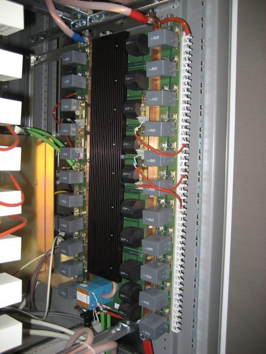
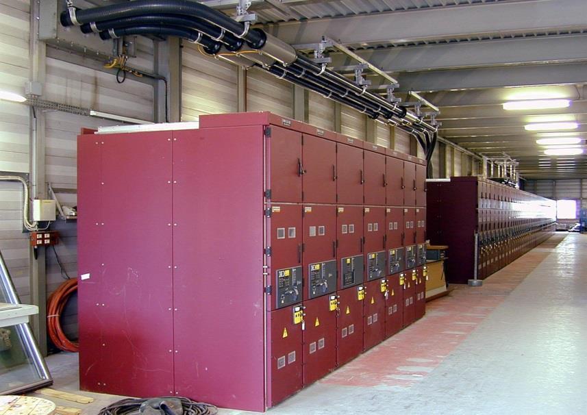
44 Series connection of sub-converters Example: SPS dipole power supply, 6kA/24kV Vmagnet 1 2 Imagnet 12 power supplies in series between magnets. Each power supply gives 6kA/2kV. In total 24kV is applied to the magnets. 44


45 45
. / converters transfer the power from the storage capacitors to the magnets. Four flying capacitors banks are not connected directly to the mains.")
46 New concept for energy management Local exchange of energy between magnets and energy storage devices inside the power supply. Done with capacitor banks integrated in the power supply. First application with POPS (PS main power system). / converters transfer the power from the storage capacitors to the magnets. Four flying capacitors banks are not connected directly to the mains. They are charged via the magnets Only two AC/ converters (called chargers) are connected to the mains and supply the losses of the system and of the magnets. AC/ converter - AFE / converter - charger module / converter - flying module MV7308 CC1 3 AC + converters OF CF11 CF1 RF1 Crwb1 TW1 MAGNETS 18KV AC Scc=600MVA Magnets Lw2 Crwb2 TW2 OF2 CF2 RF2 CF MV7308 AC AC CC2 4 Chargers 1 Lw1 2 CF12 CF22 Flying capacitors + - MAGNETS

![2000 0 0 0.2 0.4 0.6 0.8 1 1.2 1.4 1.6 1.8 U [V] I [A] Energy [J].](/docs-images/77/76439658/images/47-1.jpg "8000000 6000000 1 - -2000 + CF11 CF12 Crwb1 TW2 Lw1 TW1 Crwb2 CF21 CF22 + 2 - -4000 4000000 - MAGNETS + -6000 2000000 5 6-8000 0-10000 0 0.2 0.4 0.6 0.8 1 1.2 1.4 1.6 1.")
47 New concept for energy management AC/ converter - AFE Magnets current and voltage Stored magnetic energy / converter - charger module / converter - flying module MV KV AC Scc=600MVA MV7308 Voltage and current of the magnets Inductive Stored Energy of the magnets [J] AC AC AC MJ 6000 CC1 + OF1 - CF1 RF1 MAGNETS Lw2 CF2 RF2 OF2 - CC U [V] I [A] Energy [J] CF11 CF12 Crwb1 TW2 Lw1 TW1 Crwb2 CF21 CF MAGNETS Temps [s] Time [s] Power to the magnets Capacitor banks voltage Power from the mains = Magnet resistive losses Active power of the magnets Capacitors banks voltage Resistive Losses and charger power MW peak kV to 2kV MW Power [W] Voltage [V] Power [W] Losses Time [s] Time [s] Time [s] Acts as peak shaving for pulsed loads! 47


48 POPS example Example: POPS 6kA/±10kV 60 tons of capacitors for 18.5MJ Equivalent to 0.5L of gasoline! Control room Electrical room Cooling tower Power transformers Capacitor banks 48
 is used to")
 manages the communication, the state machine and do the current control.")
49 Power supply control The power supply are controlled by the global control system. They need to be synchronized => Timing Locally, a fieldbus (must be deterministic) is used to communicate with a gateway, WORLDFIP in the LHC ETHERNET for LINAC4 In each power supply, an electronic box (FGC) manages the communication, the state machine and do the current control. Real time software is implemented. 49


")


50 Power supply control Digital current loop Iref + - e I Reg. F(s) Vref DAC e V G(s) Voltage controlled V I B FGC High precision measurement I measured 50
 Need calibration to reference Trueness Reproducibility Uncertainty when returning to a set of previous working")

51 High-precision definition Accuracy The closeness of agreement between a test result and the accepted reference value. (ISO) Need calibration to reference Trueness Reproducibility Uncertainty when returning to a set of previous working values from cycle to cycle of the machine. I Short-term Overall precision Pulse-to-pulse Reproducibility ripple Injection instance Injection instance Stability Maximum deviation over a period with no changes in operating conditions. time 51

52 Current measurement technologies CT: invented by CERN for particle accelerators 52

53 LHC class specification Best achievements 53


54 Resolution Resolution is the smallest increment that can be induced or discerned. The resolution is expressed in ppm of maximum CT current. Resolution is directly linked to A performance. Best resolution achieved = 1ppm 54


55 Power supply workflow From power supply functional specification Charger converter Current in winding 0 Power supply design Current in winding 120 Current in winding Time[s] simulation Time[s] Time [s] Time[s] Component design 3D mechanical integration Production Minimum 18 months Up to 5 years when special development is needed. Laboratory Tests On site commissioning 55
56 What is special with magnet power supplies? The magnet power supplies are high-precision current control. The technical solutions are out the industrial standard Custom power supplies - Need very low ripple - Need current and voltage control over large range - Operation in quadrant Special topologies - Need high-precision measurement - Need high-performance electronics - Need sophisticated control and algorithm Special control electronics 56
57 Summary Power supplies are key devices for particle accelerators (like an engine in a car). Operators in control room play with power supplies to control the beams. Their performances have a direct impact on the beam quality. Creativity is required in many technical fields! More information: Special CAS on power converters 7 14 May 2014 Baden (CH) 57
Basics of Accelerator Science and Technology at CERN. Magnet powering scheme. Jean-Paul Burnet
 Basics of Accelerator Science and Technology at CERN Magnet powering scheme Jean-Paul Burnet 2 Definition What is special for magnet powering? Power electronics Converter topologies Converter association
Basics of Accelerator Science and Technology at CERN. Magnet power supplies. Jean-Paul Burnet
 Basics of Accelerator Science and Technology at CERN Magnet power supplies Jean-Paul Burnet 2 Definition What is special for powering magnets? Power supplies requirements Circuit parameters Circuit optimization
Converters for Cycling Machines
 Converters for Cycling Machines Neil Marks, DLS/CCLRC, Daresbury Laboratory, Warrington WA4 4AD, U.K. DC and AC accelerators; Contents suitable waveforms in cycling machines; the magnet load; reactive
Power converters. Definitions and classifications Converter topologies. Frédérick BORDRY CERN
 Power converters Definitions and classifications Converter topologies Frédérick BORDRY CERN "Introduction to Accelerator Physics" 19 th September 1 st October, 2010 Варна - Varna - Bulgaria Menu - Power
Power Converters. Neil Marks. STFC ASTeC/ Cockcroft Institute/ U. of Liverpool, Daresbury Laboratory, Warrington WA4 4AD, U.K.
 Power Converters Neil Marks STFC ASTeC/ Cockcroft Institute/ U. of Liverpool, Daresbury Laboratory, Warrington WA4 4AD, U.K. n.marks@dl.ac.uk Contents 1. Requirements. 2. Basic elements of power supplies.
Power Supplies in Accelerators
 Power Supplies in Accelerators Neil Marks, ASTeC, Cockcroft Institute, Daresbury, Warrington WA4 4AD, neil.marks@stfc.ac.uk Tel: (44) (0)1925 603191 Fax: (44) (0)1925 603192 Contents 1. Basic elements
6. Explain control characteristics of GTO, MCT, SITH with the help of waveforms and circuit diagrams.
 POWER ELECTRONICS QUESTION BANK Unit 1: Introduction 1. Explain the control characteristics of SCR and GTO with circuit diagrams, and waveforms of control signal and output voltage. 2. Explain the different
Power converters. Definitions and classifications Converter topologies. Frédérick BORDRY CERN
 Power converters Definitions and classifications Converter topologies Frédérick BORDRY CERN "Introduction to Accelerator Physics" 28 October - 9 November, 2012 GRANADA - SPAIN Menu - Power converter definition
CERN Accelerator School. Putting it into Practice. Jean-Paul Burnet CERN
 CERN Accelerator School Putting it into Practice Jean-Paul Burnet CERN 2 Introduction In this talk, I will try to answer to questions raised in power converter requirements I will try to propose a list
UNIVERSITY QUESTIONS. Unit-1 Introduction to Power Electronics
 UNIVERSITY QUESTIONS Unit-1 Introduction to Power Electronics 1. Give the symbol and characteristic features of the following devices. (i) SCR (ii) GTO (iii) TRIAC (iv) IGBT (v) SIT (June 2012) 2. What
PINGER MAGNET SYSTEM FOR THE ALBA SYNCHROTRON LIGHT SOURCE
 ACDIV-2015-03 May, 2015 PINGER MAGNET SYSTEM FOR THE ALBA SYNCHROTRON LIGHT SOURCE M.Pont, N.Ayala, G.Benedetti, M.Carla, Z.Marti, R.Nuñez ALBA Synchrotron, Barcelona, Spain Abstract A pinger magnet system
POPS: the 60MW power converter for the PS accelerator: Control strategy and performances
 CERN-ACC-25-98 fulvio.boattini@cern.ch POPS: the 6MW power converter for the PS accelerator: Control strategy and performances Fulvio Boattini; Jean-Paul Burnet; Gregory Skawinski CERN, Geneva, Switzerland,
CERN (The European Laboratory for Particle Physics)
") 462 IEEE TRANSACTIONS ON INSTRUMENTATION AND MEASUREMENT, VOL. 48, NO. 2, APRIL 1999 The Measurement Challenge of the LHC Project Gunnar Fernqvist Abstract In 2005, CERN is planning to commission its next
462 IEEE TRANSACTIONS ON INSTRUMENTATION AND MEASUREMENT, VOL. 48, NO. 2, APRIL 1999 The Measurement Challenge of the LHC Project Gunnar Fernqvist Abstract In 2005, CERN is planning to commission its next
Fundamentals of Power Electronics
 Fundamentals of Power Electronics SECOND EDITION Robert W. Erickson Dragan Maksimovic University of Colorado Boulder, Colorado Preface 1 Introduction 1 1.1 Introduction to Power Processing 1 1.2 Several
UNIT I POWER SEMI-CONDUCTOR DEVICES
 UNIT I POWER SEMI-CONDUCTOR DEVICES SUBJECT CODE SUBJECT NAME STAFF NAME : EE6503 : Power Electronics : Ms.M.Uma Maheswari 1 SEMICONDUCTOR DEVICES POWER DIODE POWER TRANSISTORS POWER BJT POWER MOSFET IGBT
SOLID-STATE SWITCHING MODULATOR R&D FOR KLYSTRON
 SOLID-STATE SWITCHING MODULATOR R&D FOR KLYSTRON M. Akemoto High Energy Accelerator Research Organization (KEK), Tsukuba, Japan Abstract KEK has two programs to improve reliability, energy efficiency and
EUROPEAN ORGANIZATION FOR NUCLEAR RESEARCH European Laboratory for Particle Physics
 EUROPEAN ORGANIZATION FOR NUCLEAR RESEARCH European Laboratory for Particle Physics Large Hadron Collider Project LHC Project Report 311 High Precision and High Frequency Four-Quadrant Power Converter
ELG3336: Power Electronics Systems Objective To Realize and Design Various Power Supplies and Motor Drives!
 ELG3336: Power Electronics Systems Objective To Realize and Design arious Power Supplies and Motor Drives! Power electronics refers to control and conversion of electrical power by power semiconductor
FCC Technician License Course
 FCC Technician License Course 2014-2018 FCC Element 2 Technician Class Question Pool Presented by: Tamiami Amateur Radio Club (TARC) WELCOME To the SECOND of 4, 3-hour classes presented by TARC to prepare
Chapter 9 POWER SUPPLIES
 Chapter 9 POWER SUPPLIES 9.1 Introduction The storage ring power supplies, with the exception of the injection elements are DC supplies. All the new power supplies are rated for 2.5GeV operation plus 10-15%
Chapter 1: Introduction
 1.1. Introduction to power processing 1.2. Some applications of power electronics 1.3. Elements of power electronics Summary of the course 2 1.1 Introduction to Power Processing Power input Switching converter
Power Converters for Accelerators. CERN Course on Power Converters, Baden (CH)
") Power Converters for Accelerators 2 WWW (i.e. Where Were We)? Focused on magnet power converters Good overview with many examples 3 Where do we go now? Eckoldt s contribution: Detailed compendium of Topologies
Power Converters for Accelerators 2 WWW (i.e. Where Were We)? Focused on magnet power converters Good overview with many examples 3 Where do we go now? Eckoldt s contribution: Detailed compendium of Topologies
A Highly Versatile Laboratory Setup for Teaching Basics of Power Electronics in Industry Related Form
 A Highly Versatile Laboratory Setup for Teaching Basics of Power Electronics in Industry Related Form JOHANN MINIBÖCK power electronics consultant Purgstall 5 A-3752 Walkenstein AUSTRIA Phone: +43-2913-411
Power Electronics (BEG335EC )
") 1 Power Electronics (BEG335EC ) 2 PURWANCHAL UNIVERSITY V SEMESTER FINAL EXAMINATION - 2003 The figures in margin indicate full marks. Attempt any FIVE questions. Q. [1] [a] A single phase full converter
1 Power Electronics (BEG335EC ) 2 PURWANCHAL UNIVERSITY V SEMESTER FINAL EXAMINATION - 2003 The figures in margin indicate full marks. Attempt any FIVE questions. Q. [1] [a] A single phase full converter
The Australian Synchrotron. Crowbar Less High Voltage Power Supplies (HVPS) 7th ESLS RF meeting, Oct Karl Zingre RF Engineer
 7th ESLS RF meeting, Oct Karl Zingre RF Engineer") The Australian Synchrotron Crowbar Less High Voltage Power Supplies (HVPS) 7th ESLS RF meeting, 16-17 Oct. 2003 Karl Zingre RF Engineer www.synchrotron.vic.gov.au Delivery schedule 2003 Construction works
The Australian Synchrotron Crowbar Less High Voltage Power Supplies (HVPS) 7th ESLS RF meeting, 16-17 Oct. 2003 Karl Zingre RF Engineer www.synchrotron.vic.gov.au Delivery schedule 2003 Construction works
William Thomson, Lord Kelvin, CAS2004. High Precision Measurements - Gunnar Fernqvist/CERN 1
 When you can measure what you are speaking about, and express it in numbers, you know something about it; but when you cannot measure it, when you cannot express it in numbers, your knowledge is of a meager
Energy Bank Capacitor Applications
 Energy Bank Capacitor Applications Table of Contents Introduction Electrical parameters Energy Peak current (discharge voltage) Voltage ripple Pulse Current Principle Pulse Forming Network AVX realizations
REVIEW OF SOLID-STATE MODULATORS
 REVIEW OF SOLID-STATE MODULATORS E. G. Cook, Lawrence Livermore National Laboratory, USA Abstract Solid-state modulators for pulsed power applications have been a goal since the first fast high-power semiconductor
A Series-Resonant Half-Bridge Inverter for Induction-Iron Appliances
 IEEE PEDS 2011, Singapore, 5-8 December 2011 A Series-Resonant Half-Bridge Inverter for Induction-Iron Appliances N. Sanajit* and A. Jangwanitlert ** * Department of Electrical Power Engineering, Faculty
Measurement and Analysis for Switchmode Power Design
 Measurement and Analysis for Switchmode Power Design Switched Mode Power Supply Measurements AC Input Power measurements Safe operating area Harmonics and compliance Efficiency Switching Transistor Losses
Design and Simulation of Synchronous Buck Converter for Microprocessor Applications
 Design and Simulation of Synchronous Buck Converter for Microprocessor Applications Lakshmi M Shankreppagol 1 1 Department of EEE, SDMCET,Dharwad, India Abstract: The power requirements for the microprocessor
Power Electronics (Sample Questions) Module-1
 Module-1") Module-1 Short Questions (Previous Years BPUT Questions 1 to 18) 1. What are the conditions for a thyristor to conduct? di 2. What is the common method used for protection? dt 3. What is the importance
Module-1 Short Questions (Previous Years BPUT Questions 1 to 18) 1. What are the conditions for a thyristor to conduct? di 2. What is the common method used for protection? dt 3. What is the importance
POWER ELECTRONICS. Converters, Applications, and Design. NED MOHAN Department of Electrical Engineering University of Minnesota Minneapolis, Minnesota
 POWER ELECTRONICS Converters, Applications, and Design THIRD EDITION NED MOHAN Department of Electrical Engineering University of Minnesota Minneapolis, Minnesota TORE M. UNDELAND Department of Electrical
COOPERATIVE PATENT CLASSIFICATION
 CPC H H02 COOPERATIVE PATENT CLASSIFICATION ELECTRICITY (NOTE omitted) GENERATION; CONVERSION OR DISTRIBUTION OF ELECTRIC POWER H02M APPARATUS FOR CONVERSION BETWEEN AC AND AC, BETWEEN AC AND DC, OR BETWEEN
Switched Mode Four-Quadrant Power Converters
 Switched Mode Four-Quadrant Power Converters Y. Thurel CERN, Geneva, Switzerland Abstract This paper was originally presented at CAS-2004, and was slightly modified for CAS-2014. It presents a review of
SOLID-STATE MODULATORS FOR RF AND FAST KICKERS
 UCRL-CONF-212093 SOLID-STATE MODULATORS FOR RF AND FAST KICKERS E. G. Cook, G. Akana, E. J. Gower, S. A. Hawkins, B. C. Hickman, C. A. Brooksby, R. L. Cassel, J. E. De Lamare, M. N. Nguyen, G. C. Pappas
3. Draw the two transistor model of a SCR and mention its applications. (MAY 2016)
") DHANALAKSHMI COLLEGE OF ENGINEERING DEPARTMENT OF ELECTRICAL AND ELECTRONICS ENGINEERING EE6503 POWER ELECTRONICS UNIT I- POWER SEMI-CONDUCTOR DEVICES PART - A 1. What is a SCR? A silicon-controlled rectifier
DHANALAKSHMI COLLEGE OF ENGINEERING DEPARTMENT OF ELECTRICAL AND ELECTRONICS ENGINEERING EE6503 POWER ELECTRONICS UNIT I- POWER SEMI-CONDUCTOR DEVICES PART - A 1. What is a SCR? A silicon-controlled rectifier
Current-mode PWM controller
 DESCRIPTION The is available in an 8-Pin mini-dip the necessary features to implement off-line, fixed-frequency current-mode control schemes with a minimal external parts count. This technique results
ELG4139: Power Electronics Systems Objective To Realize and Design Various Power Supplies and Motor Drives!
 ELG4139: Power Electronics Systems Objective To Realize and Design Various Power Supplies and Motor Drives! Power electronics refers to control and conversion of electrical power by power semiconductor
Switched Mode Power Conversion Prof. L. Umanand Department of Electronics Systems Engineering Indian Institute of Science, Bangalore
 Switched Mode Power Conversion Prof. L. Umanand Department of Electronics Systems Engineering Indian Institute of Science, Bangalore Lecture -1 Introduction to DC-DC converter Good day to all of you, we
MIC38C42A/43A/44A/45A
 MIC38C42A/43A/44A/45A BiCMOS Current-Mode PWM Controllers General Description The MIC38C4xA are fixed frequency, high performance, current-mode PWM controllers. Micrel s BiCMOS devices are pin compatible
Design of an 80kV, 40A Resonant SMPS for Pulsed Power Applications
 Design of an 8kV, 4A Resonant SMPS for Pulsed Power Applications Paul Nonn, Andrew Seltzman, Jay Anderson University of Wisconsin Madison Department of Physics IEEE IPMHVC June 4, 212 Three Phase Resonant
Calhoon MEBA Engineering School. Study Guide for Proficiency Testing Industrial Electronics
 Calhoon MEBA Engineering School Study Guide for Proficiency Testing Industrial Electronics January 0. Which factors affect the end-to-end resistance of a metallic conductor?. A waveform shows three complete
Understanding and Optimizing Electromagnetic Compatibility in Switchmode Power Supplies
 Understanding and Optimizing Electromagnetic Compatibility in Switchmode Power Supplies 1 Definitions EMI = Electro Magnetic Interference EMC = Electro Magnetic Compatibility (No EMI) Three Components
1. What is the unit of electromotive force? (a) volt (b) ampere (c) watt (d) ohm. 2. The resonant frequency of a tuned (LRC) circuit is given by
 volt (b) ampere (c) watt (d) ohm. 2. The resonant frequency of a tuned (LRC) circuit is given by") Department of Examinations, Sri Lanka EXAMINATION FOR THE AMATEUR RADIO OPERATORS CERTIFICATE OF PROFICIENCY ISSUED BY THE DIRECTOR GENERAL OF TELECOMMUNICATIONS, SRI LANKA 2004 (NOVICE CLASS) Basic Electricity,
Department of Examinations, Sri Lanka EXAMINATION FOR THE AMATEUR RADIO OPERATORS CERTIFICATE OF PROFICIENCY ISSUED BY THE DIRECTOR GENERAL OF TELECOMMUNICATIONS, SRI LANKA 2004 (NOVICE CLASS) Basic Electricity,
INSTITUTE OF AERONAUTICAL ENGINEERING (Autonomous) Dundigal, Hyderabad
 Dundigal, Hyderabad") I INSTITUTE OF AERONAUTICAL ENGINEERING (Autonomous) Dundigal, Hyderabad-000 DEPARTMENT OF ELECTRICAL AND ELECTRONICS ENGINEERING TUTORIAL QUESTION BANK Course Name : POWER ELECTRONICS Course Code : AEE0
I INSTITUTE OF AERONAUTICAL ENGINEERING (Autonomous) Dundigal, Hyderabad-000 DEPARTMENT OF ELECTRICAL AND ELECTRONICS ENGINEERING TUTORIAL QUESTION BANK Course Name : POWER ELECTRONICS Course Code : AEE0
Lesson 3: Electronics & Circuits
 Lesson 3: Electronics & Circuits Preparation for Amateur Radio Technician Class Exam Topics Review Ohm s Law Energy & Power Circuits Inductors & Inductance Capacitors & Capacitance Analog vs Digital Exam
R. W. Erickson. Department of Electrical, Computer, and Energy Engineering University of Colorado, Boulder
 R. W. Erickson Department of Electrical, Computer, and Energy Engineering University of Colorado, Boulder 6.3.5. Boost-derived isolated converters A wide variety of boost-derived isolated dc-dc converters
Circumference 187 m (bending radius = 8.66 m)
") 4. Specifications of the Accelerators Table 1. General parameters of the PF storage ring. Energy 2.5 GeV (max 3.0 GeV) Initial stored current multi-bunch 450 ma (max 500 ma at 2.5GeV) single bunch 70 ma
4. Specifications of the Accelerators Table 1. General parameters of the PF storage ring. Energy 2.5 GeV (max 3.0 GeV) Initial stored current multi-bunch 450 ma (max 500 ma at 2.5GeV) single bunch 70 ma
Recent Approaches to Develop High Frequency Power Converters
 The 1 st Symposium on SPC (S 2 PC) 17/1/214 Recent Approaches to Develop High Frequency Power Converters Location Fireworks Much snow Tokyo Nagaoka University of Technology, Japan Prof. Jun-ichi Itoh Dr.
MICROCONTROLLER BASED BOOST PID MUNAJAH BINTI MOHD RUBAEE
 MICROCONTROLLER BASED BOOST PID MUNAJAH BINTI MOHD RUBAEE This thesis is submitted as partial fulfillment of the requirement for the award of Bachelor of Electrical Engineering (Power System) Faculty of
SP6003 Synchronous Rectifier Driver
 APPLICATION INFORMATION Predictive Timing Operation The essence of SP6003, the predictive timing circuitry, is based on several U.S. patented technologies. This assures higher rectification efficiency
Gate drive card converts logic level turn on/off commands. Gate Drive Card for High Power Three Phase PWM Converters. Engineer R&D
 Gate Drive Card for High Power Three Phase PWM Converters 1 Anil Kumar Adapa Engineer R&D Medha Servo Drive Pvt. Ltd., India Email: anilkumaradapa@gmail.com Vinod John Department of Electrical Engineering
Power Factor Pre-regulator Using Constant Tolerance Band Control Scheme
 Power Factor Pre-regulator Using Constant Tolerance Band Control Scheme Akanksha Mishra, Anamika Upadhyay Akanksha Mishra is a lecturer ABIT, Cuttack, India (Email: misakanksha@gmail.com) Anamika Upadhyay
OVERVIEW OF SIRIUS POWER SUPPLIES
 OVERVIEW OF SIRIUS POWER SUPPLIES 6 th Power Converters for Particle Accelerators September 24 th 26 th 2018 LNLS/CNPEM Campinas - Brazil Gabriel Oehlmeyer Brunheira Power Electronics Group LNLS/CNPEM
(a) average output voltage (b) average output current (c) average and rms values of SCR current and (d) input power factor. [16]
![(a) average output voltage (b) average output current (c) average and rms values of SCR current and (d) input power factor. [16]](/thumbs/81/83006678.jpg "(a) average output voltage (b) average output current (c) average and rms values of SCR current and (d) input power factor. [16]") Code No: 07A50204 R07 Set No. 2 1. A single phase fully controlled bridge converter is operated from 230 v, 50 Hz source. The load consists of 10Ω and a large inductance so as to reach the load current
Code No: 07A50204 R07 Set No. 2 1. A single phase fully controlled bridge converter is operated from 230 v, 50 Hz source. The load consists of 10Ω and a large inductance so as to reach the load current
Contents. Acknowledgments. About the Author
 Contents Figures Tables Preface xi vii xiii Acknowledgments About the Author xv xvii Chapter 1. Basic Mathematics 1 Addition 1 Subtraction 2 Multiplication 2 Division 3 Exponents 3 Equations 5 Subscripts
Gate Drive Optimisation
 Gate Drive Optimisation 1. Background Driving of gates of MOSFET, IGBT and SiC/GaN switching devices is a fundamental requirement in power conversion. In the case of ground-referenced drives this is relatively
Maurizio Vretenar Linac4 Project Leader EuCARD-2 Coordinator
 Maurizio Vretenar Linac4 Project Leader EuCARD-2 Coordinator Every accelerator needs a linac as injector to pass the region where the velocity of the particles increases with energy. At high energies (relativity)
Power Electronics Power semiconductor devices. Dr. Firas Obeidat
 Power Electronics Power semiconductor devices Dr. Firas Obeidat 1 Table of contents 1 Introduction 2 Classifications of Power Switches 3 Power Diodes 4 Thyristors (SCRs) 5 The Triac 6 The Gate Turn-Off
2 Marks - Question Bank. Unit 1- INTRODUCTION
 Two marks 1. What is power electronics? EE6503 POWER ELECTRONICS 2 Marks - Question Bank Unit 1- INTRODUCTION Power electronics is a subject that concerns the applications electronics principles into situations
CERN - ST Division THE NEW 150 MVAR, 18 KV STATIC VAR COMPENSATOR FOR SPS: BACKGROUND, DESIGN AND COMMISSIONING
 EUROPEAN ORGANIZATION FOR NUCLEAR RESEARCH ORGANISATION EUROPÉENNE POUR LA RECHERCHE NUCLÉAIRE CERN - ST Division ST-Note-2003-023 4 April 2003 THE NEW 150 MVAR, 18 KV STATIC VAR COMPENSATOR FOR SPS: BACKGROUND,
High Voltage Generation
 High Voltage Generation Purposes (Manfaat) Company Logo High DC High AC Impulse Electron microscopes and x-ray units (high d.c. voltages 100 kv) Electrostatic precipitators, particle accelerators (few
INSTITUTE OF AERONAUTICAL ENGINEERING (AUTONOMOUS) Dundigal, Hyderabad
 Dundigal, Hyderabad") INSTITUTE OF AERONAUTICAL ENGINEERING (AUTONOMOUS) Dundigal, Hyderabad - 500 043 CIVIL ENGINEERING ASSIGNMENT Name : Electrical and Electronics Engineering Code : A30203 Class : II B. Tech I Semester Branch
INSTITUTE OF AERONAUTICAL ENGINEERING (AUTONOMOUS) Dundigal, Hyderabad - 500 043 CIVIL ENGINEERING ASSIGNMENT Name : Electrical and Electronics Engineering Code : A30203 Class : II B. Tech I Semester Branch
White Paper. Gate Driver Optocouplers in Induction Cooker. Load Pot. Control. AC Input. Introduction. What is Induction Cooking?
 Gate Driver Optocouplers in Induction Cooker White Paper Introduction Today, with the constant search for energy saving devices, induction cookers, already a trend in Europe, are gaining more popularity
Definitions of Technical Terms
 Definitions of Technical Terms Terms Ammeter Amperes, Amps Band Capacitor Carrier Squelch Diode Dipole Definitions How is an ammeter usually connected = In series with the circuit What instrument is used
Features. 5V Reference UVLO. Oscillator S R
 MIC38C42/3/4/5 BiCMOS Current-Mode PWM Controllers General Description The MIC38C4x are fixed frequency, high performance, current-mode PWM controllers. Micrel s BiCMOS devices are pin compatible with
UNIVERSITY OF BRITISH COLUMBIA
 UNIVERSITY OF BRITISH COLUMBIA DEPARTMENT OF ELECTRICAL AND COMPUTER ENGINEERING POWER ELECTRONICS LAB HANDBOOK Dr P.R. Palmer Dr P.R. Palmer 1 2004 1 AIM The aim of the project is to design, construct
R. W. Erickson. Department of Electrical, Computer, and Energy Engineering University of Colorado, Boulder
 R. W. Erickson Department of Electrical, Computer, and Energy Engineering University of Colorado, Boulder Inclusion of Switching Loss in the Averaged Equivalent Circuit Model The methods of Chapter 3 can
Entry Level Assessment Blueprint Electronics Technology
 Blueprint Test Code: 4135 / Version: 01 Specific Competencies and Skills Tested in this Assessment: Safety Practices Demonstrate safe working procedures Explain the purpose of OSHA and how it promotes
Inductive adder prototype pulse generator for FCC-hh kickers
 Inductive adder prototype pulse generator for FCC-hh kickers D. Woog Acknowledgements: M.J. Barnes, J. Holma, T. Kramer 14/04/2018 David Woog FCC WEEK 2018 1 Content Inductive adder introduction Requirements
POWER ELECTRONICS. Alpha. Science International Ltd. S.C. Tripathy. Oxford, U.K.
 POWER ELECTRONICS S.C. Tripathy Alpha Science International Ltd. Oxford, U.K. Contents Preface vii 1. SEMICONDUCTOR DIODE THEORY 1.1 1.1 Introduction 1.1 1.2 Charge Densities in a Doped Semiconductor 1.1
Frequently Asked Questions (FAQs) MV1000 Drive
 MV1000 Drive") QUESTION 1. What is a conventional PWM Inverter? 2. What is a medium voltage inverter? 3. Are all MV inverters Voltage Source (VSI) design? 4. What is a Current Source Inverter (CSI)? 5. What output power
QUESTION 1. What is a conventional PWM Inverter? 2. What is a medium voltage inverter? 3. Are all MV inverters Voltage Source (VSI) design? 4. What is a Current Source Inverter (CSI)? 5. What output power
Conventional Single-Switch Forward Converter Design
 Maxim > Design Support > Technical Documents > Application Notes > Amplifier and Comparator Circuits > APP 3983 Maxim > Design Support > Technical Documents > Application Notes > Power-Supply Circuits
University of Jordan School of Engineering Electrical Engineering Department. EE 219 Electrical Circuits Lab
 University of Jordan School of Engineering Electrical Engineering Department EE 219 Electrical Circuits Lab EXPERIMENT 4 TRANSIENT ANALYSIS Prepared by: Dr. Mohammed Hawa EXPERIMENT 4 TRANSIENT ANALYSIS
ECET 211 Electric Machines & Controls Lecture 9-1 Adjustable-Speed Drives and PLC Installations (1 of 2)
") ECET 211 Electric Machines & Controls Lecture 9-1 Adjustable-Speed Drives (1 of 2) Text Book: Electric Motors and Control Systems, by Frank D. Petruzella, published by McGraw Hill, 2015. Paul I-Hai Lin,
ECET 211 Electric Machines & Controls Lecture 9-1 Adjustable-Speed Drives (1 of 2) Text Book: Electric Motors and Control Systems, by Frank D. Petruzella, published by McGraw Hill, 2015. Paul I-Hai Lin,
ECE1750, Spring Week 1 - Components
 ECE1750, Spring 2018 Week 1 - Components 1 Most commonly used power electronic switches: Diodes(aka (a.k.a. rectifiers) Thyristors (a.k.a. silicon controlled rectifiers, SCRs) Power MOSFETs IGBTs 2 But
DOWNLOAD PDF POWER ELECTRONICS DEVICES DRIVERS AND APPLICATIONS
 Chapter 1 : Power Electronics Devices, Drivers, Applications, and Passive theinnatdunvilla.com - Google D Download Power Electronics: Devices, Drivers and Applications By B.W. Williams - Provides a wide
POWER- SWITCHING CONVERTERS Medium and High Power
 POWER- SWITCHING CONVERTERS Medium and High Power By Dorin O. Neacsu Taylor &. Francis Taylor & Francis Group Boca Raton London New York CRC is an imprint of the Taylor & Francis Group, an informa business
Practical Tricks with Transformers. Larry Weinstein K0NA
 Practical Tricks with Transformers Larry Weinstein K0NA Practical Tricks with Transformers Quick review of inductance and magnetics Switching inductive loads How many voltages can we get out of a $10 Home
Power Electronics. P. T. Krein
 Power Electronics Day 10 Power Semiconductor Devices P. T. Krein Department of Electrical and Computer Engineering University of Illinois at Urbana-Champaign 2011 Philip T. Krein. All rights reserved.
Switches And Antiparallel Diodes
 H-bridge Inverter Circuit With Transistor Switches And Antiparallel Diodes In these H-bridges we have implemented MOSFET transistor for switching. sub-block contains an ideal IGBT, Gto or MOSFET and antiparallel
Design and implementation of a LLC-ZCS Converter for Hybrid/Electric Vehicles
 Design and implementation of a LLC-ZCS Converter for Hybrid/Electric Vehicles Davide GIACOMINI Principal, Automotive HVICs Infineon Italy s.r.l. ATV division Need for clean Hybrid and Full Electric vehicles
APAC 2007, Raja Ramanna Centre for Advanced Technology(RRCAT), Indore, India LHC STATUS. Lyndon Evans, CERN, Geneva, Switzerland
, Indore, India LHC STATUS. Lyndon Evans, CERN, Geneva, Switzerland") LHC STATUS Lyndon Evans, CERN, Geneva, Switzerland Abstract The installation of the Large Hadron Collider at CERN is now approaching completion. Almost 1100 of the 1232 main bending magnets are installed
LHC STATUS Lyndon Evans, CERN, Geneva, Switzerland Abstract The installation of the Large Hadron Collider at CERN is now approaching completion. Almost 1100 of the 1232 main bending magnets are installed
MIC4421/4422. Bipolar/CMOS/DMOS Process. General Description. Features. Applications. Functional Diagram. 9A-Peak Low-Side MOSFET Driver
 9A-Peak Low-Side MOSFET Driver Micrel Bipolar/CMOS/DMOS Process General Description MIC4421 and MIC4422 MOSFET drivers are rugged, efficient, and easy to use. The MIC4421 is an inverting driver, while
BLOCK DIAGRAM OF THE UC3625
 U-115 APPLICATION NOTE New Integrated Circuit Produces Robust, Noise Immune System For Brushless DC Motors Bob Neidorff, Unitrode Integrated Circuits Corp., Merrimack, NH Abstract A new integrated circuit
The Quest for High Power Density
 The Quest for High Power Density Welcome to the GaN Era Power Conversion Technology Drivers Key design objectives across all applications: High power density High efficiency High reliability Low cost 2
Current Mode PWM Controller
 Current Mode PWM Controller UC1842/3/4/5 FEATURES Optimized For Off-line And DC To DC Converters Low Start Up Current (
Power Converters and Power Quality
 Power Converters and Power Quality Karsten KAHLE, CERN karsten.kahle@cern.ch, Baden (CH) 2 References EN 50160 (2010) IEC 61000 IEC 61000-2-2 IEC 61000-2-4 IEC 61000-2-12 IEC 61000-3-4 IEC 61000-3-6 IEC
In addition to the power circuit a commercial power supply will require:
 Power Supply Auxiliary Circuits In addition to the power circuit a commercial power supply will require: -Voltage feedback circuits to feed a signal back to the error amplifier which is proportional to
Chapter 3 : Closed Loop Current Mode DC\DC Boost Converter
 Chapter 3 : Closed Loop Current Mode DC\DC Boost Converter 3.1 Introduction DC/DC Converter efficiently converts unregulated DC voltage to a regulated DC voltage with better efficiency and high power density.
Workshop Matlab/Simulink in Drives and Power electronics Lecture 4
 Workshop Matlab/Simulink in Drives and Power electronics Lecture 4 : DC-Motor Chopper design SimPowerSystems Ghislain REMY Jean DEPREZ 1 / 20 Workshop Program 8 lectures will be presented based on Matlab/Simulink
K6RIA, Extra Licensing Class. Circuits & Resonance for All!
 K6RIA, Extra Licensing Class Circuits & Resonance for All! Amateur Radio Extra Class Element 4 Course Presentation ELEMENT 4 Groupings Rules & Regs Skywaves & Contesting Outer Space Comms Visuals & Video
Lecture 19 - Single-phase square-wave inverter
 Lecture 19 - Single-phase square-wave inverter 1. Introduction Inverter circuits supply AC voltage or current to a load from a DC supply. A DC source, often obtained from an AC-DC rectifier, is converted
Tens kilowatts power supply based on half-bridge inverter with zero current commutation
 Tens kilowatts power supply based on half-bridge inverter with zero current commutation A.V. Akimov,, A.A. Pachkov For the pulse power supply of the VEPP- 5 injector klystrons the 40 kw, 50 kv modulators
New lossless clamp for single ended converters
 New lossless clamp for single ended converters Nigel Machin & Jurie Dekter Rectifier Technologies Pacific 24 Harker St Burwood, Victoria, 3125 Australia information@rtp.com.au Abstract A clamp for single
Five years of operational experience with digitally controlled Power Supplies for beam control at the Paul Scherrer Institut (PSI)
") Five years of operational experience with digitally controlled Power Supplies for beam control at the Paul Scherrer Institut (PSI) Keywords F. Jenni, R. Künzi, A. Lüdeke 1, L. Tanner 2 PSI, Paul Scherrer
Five years of operational experience with digitally controlled Power Supplies for beam control at the Paul Scherrer Institut (PSI) Keywords F. Jenni, R. Künzi, A. Lüdeke 1, L. Tanner 2 PSI, Paul Scherrer
BEST BMET CBET STUDY GUIDE MODULE ONE
 BEST BMET CBET STUDY GUIDE MODULE ONE 1 OCTOBER, 2008 1. The phase relation for pure capacitance is a. current leads voltage by 90 degrees b. current leads voltage by 180 degrees c. current lags voltage
CHAPTER 5 POWER QUALITY IMPROVEMENT BY USING POWER ACTIVE FILTERS
 86 CHAPTER 5 POWER QUALITY IMPROVEMENT BY USING POWER ACTIVE FILTERS 5.1 POWER QUALITY IMPROVEMENT This chapter deals with the harmonic elimination in Power System by adopting various methods. Due to the
Usage of DSP and in large scale power converter installations (LHC)*
*") Usage of DSP and in large scale power converter installations (LHC)* Presented by H.Schmickler Seminar prepared for the CAS on Digital Signal Processing Sigtuna (Sweden), June 2007 A CERN power converter
Usage of DSP and in large scale power converter installations (LHC)* Presented by H.Schmickler Seminar prepared for the CAS on Digital Signal Processing Sigtuna (Sweden), June 2007 A CERN power converter