Power converters. Definitions and classifications Converter topologies. Frédérick BORDRY CERN
|
|
|
- Mae Newton
- 6 years ago
- Views:
Transcription


1 Power converters Definitions and classifications Converter topologies Frédérick BORDRY CERN "Introduction to Accelerator Physics" 28 October - 9 November, 2012 GRANADA - SPAIN
 - Pulsed power converters - Control and precision - Conclusions In 1 hour???? 2")
2 Menu - Power converter definition and classification - Power converter topologies: line commutated and switch mode based Sources, power switches (semiconductors), commutation rules, - Special case for magnet powering (Voltage source - Current source) - Pulsed power converters - Control and precision - Conclusions In 1 hour???? 2
![High energy physics and power converters The «Nobel prize» power converter : [Cockroft & Walton] who in](/docs-images/79/79241598/images/3-1.jpg "1932 used this voltage multiplier to power their particle accelerator, performing the first artificial")


3 High energy physics and power converters The «Nobel prize» power converter : [Cockroft & Walton] who in 1932 used this voltage multiplier to power their particle accelerator, performing the first artificial nuclear disintegration in history. They used this cascade circuit for most of their research, which in 1951 won them the Nobel Prize in Physics for "Transmutation of atomic nuclei by artificially accelerated atomic particles". Schematic of Cockcroft and Walton s voltage multiplier. Opening and closing the switches S, S transfers charge from capacitor K3 through the capacitors X up to K1. Voltage multiplier : switches 3


4 On a new principle for the production of higher voltages. The difficulties of maintaining high voltages led several physicists to propose accelerating particles by using a lower voltage more than once. learned of one such scheme in the spring of 1929, while browsing through an issue of Archiv für Elektrotechnik, a German journal for electrical engineers. Lawrence read German only with great difficulty, but he was rewarded for his diligence: he found an article by a Norwegian engineer,, the title of which he could translate as On a new principle for the production of higher voltages. The diagrams explained the principle and Lawrence skipped the text. 4
 black box able to convert MAD files into currents (Accelerator Physics group member) An equipment with three")
 A big box with wires and pipes everywhere and blinking lamps. Occasionally it goes BANGG!")
5 Power converters : Definitions The source of the beam blow-up when we could not prove it was the RF (Control room operator) A powerful (small) black box able to convert MAD files into currents (Accelerator Physics group member) An equipment with three states, ON, OFF and FAULT (Another operator) Is it the same thing as a power supply? (Person from another physics lab) A big box with wires and pipes everywhere and blinking lamps. Occasionally it goes BANGG! (Former CERN Power Converter Group secretary view) 5
 A standard piece of equipment available from industry off-the-shelf (a higher management person, not in in this")
6 Power converters : Definitions (cont d) That which feeds the magnets (a visitor) A stupid installation taking a non-sinusoidal current at poor power factor (Power distribution engineer) A standard piece of equipment available from industry off-the-shelf (a higher management person, not in in this room!) 6
7 Power converters specifications "Do you have one or two power converters for the test of magnet prototypes? 40 A will be enough? Precision is not important for time being. Don t worry it s not urgent. Next month is OK " ( received ) 40A power converter: Size? Weight? Cost? 7
8 [40A, 100 kv,] klystron power converter DC Power: 4 MW DC operation 8
9 Pulsed klystron modulators for LINAC 4 Specification symbol Value unit Output voltage V kn 110 kv Voltage [V] V kn V ovs FTS Output current I out 50 A Pulse length t rise +t set +t flat +t fall 1.8 ms ideal pulse real pulse Flat-Top stability FTS <1 % Repetition rate 1/T rep 2 Hz t rise t set t flat t fall T rep t reset V uns Time [s] Peak power : 5.5MW Average power: 20kW 9
![LHC orbit corrector : [±60A,±8V] Magnet : L=7 H ; R = 30 mw (60m of 35 mm 2 ) T = L/R = 300 s => f OL B 0.5 mhz U static = R.I = 1.](/docs-images/79/79241598/images/10-0.jpg "8V 6 V for the di/dt with L= 7 H (di/dtmax 1A/s) OK Small signal : f CL B 1 Hz : DI = 0.1 A = 0.")
10 LHC orbit corrector : [±60A,±8V] Magnet : L=7 H ; R = 30 mw (60m of 35 mm 2 ) T = L/R = 300 s => f OL B 0.5 mhz U static = R.I = 1.8V 6 V for the di/dt with L= 7 H (di/dtmax 1A/s) OK Small signal : f CL B 1 Hz : DI = 0.1 A = 0.15 % Imax The power converters involved in feedback of the local orbit may need to deal with correction rates between 10 and 500 Hz ; f CL B 50Hz (DI = 1% : Umax = 2400 V?????...) (U max = 8V => DI = 30 ppm Imax at 50 Hz) 10
11 Power converters specifications "Do you have one or two power converters for the test of magnet prototypes? 40 A will be enough? Precision is not important for time being. Don t worry it s not urgent. Next month is OK " ( received ) Need of more specification data: - Output Voltage - DC or Pulsed (pulse length and duty cycle) - Output voltage and current reversibility - Precision (short and long term) - Ripple (load definition) Environment conditions: grid, volume, water,... 11


12 Energy source Applications Traction and auxiliary 50 or 60 Hz ; AC The task of a power converter is to process and control the flow of electric energy by supplying voltages and currents in a form that is optimally suited for user loads. Domestic Appliance Medical applications Industrial applications, Welding, Induction Heating,. DC current Control 12
, reparability (MTTR), - effect on environment (EMI, noise,.")
13 Ii Control Power Converter Io Source Vi Topologies Vo Source Electrical energy transfer Power Converter Design - performance - efficiency - reliability (MTBF), reparability (MTTR), - effect on environment (EMI, noise,...) - low cost 13

14 Source definition Source definition: any element able to impose a voltage or a current, independently of, respectively, the current flowing through, or the voltage imposed at its terminals. A source could be a generator or a receptor. Two types of sources: Voltage source which imposes a voltage independently of the current flowing through it. This implies that the series impedance of the source is zero (or negligible in comparison with the load impedance) Current source which imposes a current independently of the voltage at its terminals. This implies that the series impedance of the source is infinite (or very large in comparison with the load impedance) 14
15 Source characteristics Voltage source Turn On impossible V Current source I Turn Off impossible 15
16 Commutation rules electronic switches modify the interconnection of impeding circuits any commutation leading instantaneous variations of a state variable is prohibited V1 V2 I1 I2 Turn On impossible Turn Off impossible Interconnection between two impeding networks can be modified only if : - the two networks are sources of different natures (voltage and current) - the commutation is achieved by TWO switches. The states of the two switches must be different. 16


17 Commutation U I U I U I Direct Link Inverse Link Open Link Active components used as switches to create a succession of link and no link between sources to assure an energy transfer between these sources with high efficiency. 17
18 Direct link configuration : Direct voltage-current converters U I U I U I a b c Connexion (energy flow between sources) Disconnexion (current source short-circuited, voltage source open circuited) U K1 I K4 - K1 and K3 closed => a - K2 and K4 closed => b K2 K3 - K1 and K4 (or K2 and K3) closed => c 18


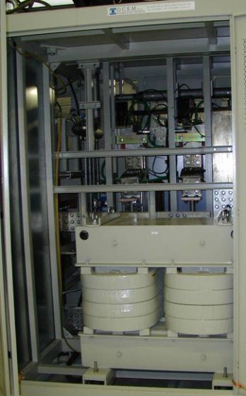
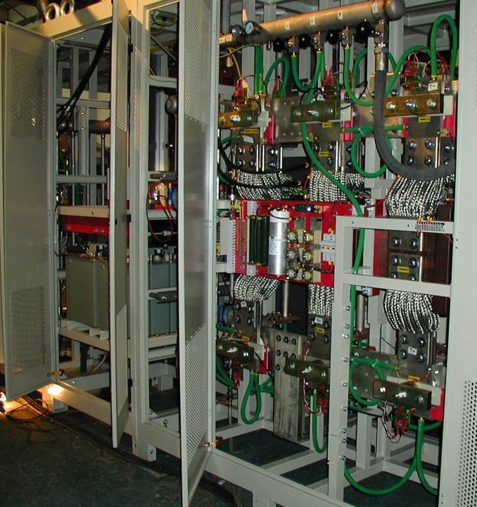
19 Once upon a time. not so far This is a 6-phase device, 150A rating with grid control. It measures 600mm high by 530mm diameter. 19
20 Power Semicondutors OFF ON ON Ik Ik Ik Vk Vk Vk Power Semiconductors Turn - off Devices Thyristors Diodes Transistors Thyristors Line commutated Fast Bi - directional Pulse Fast Line commutated Avalanche MOSFETs Darlingtons IGBTs GTOs IGCTs 20

 Link to frequency of the electrical network")

21 Evolution of Power Switches From mercury arc rectifier, grid-controlled vacuum-tube rectifier, inignitron,. to solid state electronics (semiconductors) Power Diode and Thyristor or SCR (Silicon-Controlled Rectifier ) Link to frequency of the electrical network 50 Hz (60 Hz) High frequency power semiconductors : MosFet, IGBTs, GTOs, IGCTs,. High frequency => high performances (ripple, bandwidth, perturbation rejection,...) small magnetic (volume, weight) 21
 22")
22 Power semiconductor switches capabilities Effective(*) switching capabilities & IGCT (*) Voltage de-rating: 1.6; Current de-rating: ~1.3; (i.e., power de-rating: 1.6 x 1.3 2) 22
")

23 Power Converter for magnets AC I G V G Power Converter Topologies I L V L Load DC 3 phase mains (50 or 60 Hz) magnet, solenoid, Voltage source Control Current Current source source Achieving high performance : COMPROMISE 23
24 Operating Modes V V I Quadrant mode Output Source I Quadrants mode V I Quadrants mode V I 24
25 General power converter topologies 1 Rectifier F i l t e r s AC Voltage Source DC Current Source 25
26 Direct Converters : Rectifiers AC Voltage Ik Vk DC Current F i l t e r s Thyristors 26
27 SPS Main power converters Main power converters 12 x [6kA, 2 kv] 27

28 Two Quadrant Phase Controlled Rectifiers for high current SC magnets +15 o 3 Phase 50/60 Hz Supply -15 o LHC main bending power converters [13 ka, 190 V] 28
29 29
30 Direct Converters : Rectifiers AC Voltage Ik Vk AC DC Current F i l t e r s
31 Direct Converters : Phase Controlled Rectifiers J very high power capability J moderate prices and competitive market J simple structure, well understood (but care needed with high currents) L three phase transformer operates at low frequency (50 or 60 Hz) L variable power factor from 0 to 0.8 L harmonic content on input current L response time is large (ms) L current ripple is large (passive or active filters) passive (active) filters operating at low frequency Increase of pulse number (3,6,12,24,48) but complexity (cost, control,...) 31
32 General power converter topologies 1 Rectifier 2 CV1 AC Link CV2 F i l t e r s Application Application ::- - very high currents voltages with with low low voltages currents - (very - very high high voltages currents with with low low currents) voltages 32
33 Direct Converters : AC link (AC line controller) AC link J Simple diode rectifier on output stage J Easier to handle high current (or voltage) L Only One Quadrant operation AC Thyristor line controller at reasonable current (or voltage) F i l t e r s + - DC 33
![[100 kv, 40A]](/docs-images/79/79241598/images/34-1.jpg "klystron")

34 [100 kv, 40A] klystron power converter DC operation 34

35 General power converter topologies 1 Rectifier 2 CV1 AC Link CV2 3 CV1 DC Link CV2 F i l t e r s Rectifier Voltage Source Current Source Voltage Source Current Source 35
36 Galvanic isolation at AC input source (50Hz transformer) I 50 Hz transformer Optimal voltage output Galvanic isolation CV1 Diode bridge 6 or 12 pulses CV2 PWM Converter Hard switching Magnet 36

37 New PS Auxiliary Power Converters DC Inductance Brake Chopper Capacitors bank IGBT H bridge Peak Power: Voltage: Max Current: 405 kw ± 900V ± 450A 400V Transformer 50Hz D-Y Y Diodes rectifier HF Filter Crowbar Magnet Y Crowbar Multi-Turn Extraction: Current/Voltage waveforms 720V Peak 350 A Peak 14 ms Current Loop Bandwidth 1kHz 37
 (often diode rectifier) HF transformer to provide the galvanic isolation f Vol. AC-DC LF + - DC-AC HF (Inverter) AC-DC HF DC link HF AC link 38")
38 Indirect AC-DC-AC-DC converter Three cascade power conversion stages: 1) Simple DC source (Diode (thyristor) rectifiers) 2) HF DC-AC converter (Inverter) 3) HF AC-DC converter (Rectifier) (often diode rectifier) HF transformer to provide the galvanic isolation f Vol. AC-DC LF + - DC-AC HF (Inverter) AC-DC HF DC link HF AC link 38
 good power factor (0.")
39 LHC Switch-Mode Power Converters AC 50 Hz DC AC khz DC Passive high-current Output stage HF CV1 CV2 CV3 Magnet Voltage loop: bandwidth few khz Fast power semiconductors (IGBT) Semiconductor losses : soft commutation HF transformer and output filter : ferrite light weight, reduced volume (HF transformers and filters) good power factor (0.95) high bandwidth and good response time Soft commutation gives low losses and low electrical noise small residual current ripple at output More complex structure, less well understood, limited number of manufacturers 39

![[13kA,18V] : 5*[3.](/docs-images/79/79241598/images/40-1.jpg "25kA,18V] - [8kA,8V] : 5*[2kA,8V]")
![- [6kA,8V] : 4*[2kA,8V] - [4kA,8V]](/docs-images/79/79241598/images/40-2.jpg ": 3*[2kA,8V] MTBF and MTTR")
40 LHC:1-quadrant converter: modular approach 1-quadrant converters: - [13kA,18V] : 5*[3.25kA,18V] - [8kA,8V] : 5*[2kA,8V] - [6kA,8V] : 4*[2kA,8V] - [4kA,8V] : 3*[2kA,8V] MTBF and MTTR optimization [2kA, 8V] 40
41 DC and slow pulsed converters Rise and fall time > few ms Control of the ramps High and medium power Phase Controlled Rectifiers - Diodes and thyristors rectifiers - 50Hz transformers and magnetic component (filters) - 1-quadrant and 2-quadrants (but unipolar in current) : energy back to the mains - 4-quadrant: back-to-back converters Low and Medium power Switch-mode power converters - Mosfets, IGBTs, IGCTs, turn-off semiconductors - HF transformers and passive filters - excellent for 1-quadrant converter - 4-quadrant converters but with energy dissipation (very complex structure if energy has to be re-injected to mains) 41
42 Pulsed converters Synchrotrons Beam is injected, accelerated and extracted in several turns; Linac s and transfer lines Beam is passing through in one shot, with a given time period; B (T), extraction B (T), Beam passage I (A) I (A) acceleration injection t (s) t (s) Rise and fall time < few ms Direct Energy transfer from mains is not possible: Intermediate storage of energy Peak power : could be > MW ( average power kw) 42
43 Block schematic of a fast pulsed converter DISCHARGE UNIT & ENERGY RECOVER SWITCHING MATRIX MAINS CAPACITOR CHARGER POWER CONVERTER CAPACITOR BANK ACTIVE FILTER LOAD (MAGNET) Start / Stop Charge Ucharge.ref Start / Stop Active Filter Start Discharge / Start Recovery GAIN CURRENT REGULATOR S Iload - Iload.ref + Pulses TIMING UNIT Machine Timing Start Charge Stop Charge Start Pulse Measure time Active filter on Iload Charge Ucharge Recovery Discharge 43


44 High current, high voltage discharge capacitor power converters CNGS horn and reflector power converters 50 ms 6 ms 150 ka for the horn 180 ka for the reflector CNGS cycles 44
45 Capacitor bank charger power converter, PS1-120 kv max Pulsed klystron modulators for LINAC 4 Specification symbol Value unit Output voltage V kn 110 kv Output current I out 50 A Pulse length t rise +t set +t flat +t fall 1.8 ms Flat-Top stability FTS <1 5 Repetition rate 1/T rep 2 Hz Voltage [V] V kn t rise V ovs ideal pulse t set t flat t fall T rep FTS Peak power : 5.5MW Average power: 20kW real pulse t reset V uns Time [s] PS1, PS3, PS4 - Commercial PS2 - CERN made 120 kv High voltage cables 12 kv max V PS1 0.1 mf 120 kv High voltage connectors Main solid state switches DRIVER DRIVER Capacitor discharge system V PS2 PULSE TRANSFORMER (OIL TANK) 1:10 Vout Anode power Filament power converter, PS3 converter, PS4 DC K1 A1 DC DIODE RECTIFIER A K Hign Frequency ISOLATION TRANSFORMER F KLYSTRON (OIL TANK) A - Anode; C - Collector; K - Cathode; F - Filament Droop compensation power converter or bouncer, PS2 C 45

46 Vk (kv) Vk (kv) Pulsed klystron modulators for LINAC 4 Specification symbol Value unit Output voltage V kn 110 kv Output current I out 50 A Pulse length t rise +t set +t flat +t fall 1.8 ms Flat-Top stability FTS <1 5 Repetition rate 1/T rep 2 Hz Load Voltage µs Beam passage E+00 2.E-04 4.E-04 6.E-04 8.E-04 1.E-03 1.E-03 time (s) Load Current Test phase: Water cooled dummy loads 2.5T each!
47 Load Power Converter % Load AC Supply Power Part Local control Reference Control Transducer Load characteristics are vital. Transfer function is a must! 47
 Current loop")
 DAC Vref e V G(s) V I B I")
48 Example :LHC power converter control Digital (or analogue) Current loop Voltage loop Iref + - e I Reg. F(s) DAC Vref e V G(s) V I B I measured 48


49 Power converter :Performance requirements Iref I V I B Imeas.? 49
50 Precision Glossary Accuracy Long term setting or measuring uncertainty taking into consideration the full range of permissible changes* of operating and I environmental conditions. Meas. * requires definition ± Accuracy ppm * I Nominal Reproducibility Uncertainty in returning to a set of previous working values from cycle to cycle of the machine. Stability Cycle 1 Cycle 2 Cycle 3 I B1 I B2 I B3 Maximum deviation over a period with no changes in operating conditions. T R I Nominal Accuracy, reproducibility and stability are defined for a given period Precision is qualitative. Accuracy, reproducibility, stability are quantitative. T S 50

51 Resolution The resolution is expressed in ppm of I Nominal. Resolution is directly linked to A/D system Smallest increment that can be induced or discerned. I* ref ± DI* ref I B DAC V I* meas. ± DI* ADC I meas + DI. 51
52 Current offset in Milliamps Results of Resolution Test with the LHC Prototype Digital Controller Current offset in ppm of 20 ka 80 I 0 = Amps Reference Measured Time in Seconds 52
 Voltage ripple is defined by the power converter Current ripple : load transfer function (cables, magnet inductance, ) (good identification is required if the load is a")
53 RIPPLE Power converter V Load H(s) I Magnet F(s) Control V = R. I + L. di/dt => H(s) = 1/ (L/R. s + 1) Voltage ripple is defined by the power converter Current ripple : load transfer function (cables, magnet inductance, ) (good identification is required if the load is a long string of magnets ) Field ripple : magnet transfer function (vacuum chamber, ) 53
54 Power converters specifications "Do you have one or two power converters for the test of magnet prototypes? 40 A will be enough? Precision is not important for time being. Don t worry it s not urgent. Next month is OK " ( received ) Load characteristics : I and V reversibility ( 1, 2 or 4-quadrants?) ; Transfer function (at least R, L, C) => will define V and then power Range : Imax (and Imin) Rise and fall time (di/dt max; voltage constraint on the load); is the precision an issue during the ramps (beam or no beam) => Pulsed converters with intermediate storage? => bandwidth (topology and control strategy) Precision: accuracy, reproducibility, stability - Resolution Ripple: DV(f) => passive (or active) filters ; control strategy (SMPC) Is the volume a constraint? Is water cooling possible? Environment: temperature and humidity; EMI conditions, radiation, Hardware design and production take time.. 54

 Numerical verification of selected topology (dedicated numerical")
 4 1 1 1 3 3 2 5 5 5 5 3D Mechanical integration &")
 Load examples: - Magnet (high current) - Klystron (High Voltage) -")
55 Utility grid specs (Voltage, power quality, ) Power Converter Design: Typical R&D procedure Efficiency, cost, volume, EMI,, specs Specs analysis for topology selection (1,2,4 quadrants, active/passive converter closed/open loop regulation, switches technology, ) Numerical verification of selected topology (dedicated numerical simulations for general converter functionality) Components design and/or specifications (analytical or numerical approaches) D Mechanical integration & construction Laboratory tests On site commissioning Load specs (L, R, C values, precision, ) Load examples: - Magnet (high current) - Klystron (High Voltage) - Particles source (HV) - RF equipment (HV) 55


56 CAS - CERN Accelerator School : Power converters for particle accelerators Mar 1990, Switzerland CAS - CERN Accelerator School : Specialised CAS Course on Power Converters for particle accelerators May Warrington, UK 2014: Next Specialised CAS Course on Power Converters for particle accelerators 56

57 57
58 Energy conversion : transfer of energy between two sources Introductive example I i I o U i U o Converter I i I o U i U o Linear solution Transfer of energy between - DC voltage source Ui - DC source (nature is not defined) : Uo, Io 58
59 Linear solution U i = 24V ; U o = 10 V and I o = 600A Po = Uo. Io = = W U i I i I o T U o P T (power dissipated by the switch) = U T. I T = (Ui Uo). Io = (24 10). 600 = W Converter efficiency = Po / (P T + Po) = 42 %!!!!! Furthermore, it ll be difficult to find a component (semiconductor) able to dissipate W. Then impossible for medium and high power conversion Commutation - U T 0 if I T 0 - I T = 0 if U T 0 Linear mode P T 0 (if power switches are ideal) switch mode (power switches either saturated or blocked) 59


60 Power Converter topology synthesis: the problem the interconnection of sources by switches Fundamental rules and source natures Power converter topologies switch characteristics Ik Ik Vk Vk 60
 Vk OFF state")
61 Switch characteristics Switch : semiconductor device functioning in commutation The losses in the switch have to be minimized Zon very low Zoff very high Ik Ik ON state Vk Switch : at least two orthogonal segments (short and open circuit are not switches) Vk OFF state 61
62 Classification of switches According to the degree of controllability: Diodes: On and Off states controlled by the power circuit (uncontrolled). Thyristors: Turned On by a control signal but turned off by the power circuit (semicontrolled). Transistors: Controllable switches. Can be turned On and Off by a control signal. For analysis purposes power switches are usually considered ideal: Instantaneous, lossless, and infinite current and voltage handling capability. 62


63 press-pack case (high power) Diodes modules case (medium power) 2 terminals device. An ideal diode turns On when forward biased and Off when its forward current goes to zero. Other cases (low power) Ex: 6 kv pk, 3 ka av Ex: 1.8 kv pk, 80A av SOT-227 Minibloc case Ex: 1000V pk, 2x30A av DO-203 Stud case Ex: 800V TO-220 case pk, 110A av Ex: 600V pk, 30A av 63

 modules case (medium power) Other cases (low power) TO-93 case Ex: 4.8kV pk, 3.")
64 Thyristor (Silicon Controlled Rectifier - SCR) 3 terminals device. 3 main operating regions. Latches On by a gate current pulse when forward biased and turns Off as a diode. Requires low power gate drives and is very rugged. press-pack case (high power) modules case (medium power) Other cases (low power) TO-93 case Ex: 4.8kV pk, 3.2 ka av Ex: 1.8 kv pk, 500A av Ex: 1200V pk, 325A av TO-220 case Ex: 800V64 pk, 20A av TO-208 Stud case Ex: 800V pk, 30A av 64
65 Controllable switches Used in forced-commutated converters (f sw > 60 Hz ) Different types: MOSFET, IGBT, GTO, IGCT. Gate requirements and performance are quite different. Generic switch: Current flows in the direction of the arrow when the device in On. Generic controllable switch 65
 device. Fast commutation times (tens to hundreds of ns).")

66 MOSFET SMD-220 case Ex: 200V, 70A TO-247 case Ex: 200V, 130A High input impedance on the gate (voltage controlled) device. Fast commutation times (tens to hundreds of ns). Low switching losses; Low On state resistance (R DS_On ). Easy paralleling Limited in voltage and power handling capabilities. Great for low voltage (V DS <250V) and low current (I DS <150A) applications. 66
")
 High input impedance for controls (between")

 switching")
 -> Moderate switching losses Other cases")
67 Ex: 4.5kV, 2.4 ka Ex: 1.7 kv, 3.6kA Insulated Gate Bipolar Transistor (IGBT) press-pack case (high power) modules case (medium power) High input impedance for controls (between gate (G) and emitter (E) ) thanks to the use of a MOSFET. High voltage devices have low on state voltage drops, like a BJT High current (high power) switching capabilities; Fast switching (typ. < 500ns) -> Moderate switching losses Other cases (low power) Semix Mini Skiip Ex: 1200V, 400A Semitop (6 IGBT s) Ex: 600V, 50A (6 IGBT s) Ex: 600V, 100A (6 IGBT s) 67
; Blocks negative voltages but has low switching speeds; Still used in ultra high power applications. press-pack case (ultra high power) Ex: 4.")
68 Gate-Turn-Off (GTO) thyristor Turns on and latches as an SCR but requires a large (I AK /3) negative gate current to turnoff (elaborated gate control circuit); Blocks negative voltages but has low switching speeds; Still used in ultra high power applications. press-pack case (ultra high power) Ex: 4.5kV, 4 ka 68
69 Comparison of controllable switches Effective(*) switching obsolete Most popular (low power) Most popular (high power) (< ~ 15 kw) (< ~ 10 MW) (< ~ 3 MW) (~0.1µs) (~ 5µs) (~0.5µs) (*) Voltage de-rating: 1.6; Current de-rating: ~1.3 (i.e., power de-rating: 1.6 x 1.3 2) 69

70 Reactive Components of Power Converters Inductors & Capacitors Functionalities in Power Converters - Electrical Energy storage (POPS, SMES, indirect-link converters) - Adaptation of converter I/O sources (DC or AC current & voltage filters, Bouncers...) - Phase control of power flow through HF resonant LC stage - Implementation of non dissipative commutation (ZCS or ZVS snubbers) Transformer Functionalities in Power Converters - Galvanic Isolation - High Voltage or Low Voltage converters (Klystrons or Magnets) Reactive Components can degrade: - Converter Efficiency - Converter Power Density: W/m 3 & W/kg - Converter Control Bandwidth: Filter Time constants 70
 1 2 W 4 mag LI Ku. B. J. Ae. SCu B J.")
71 Reactive Components of Power Converters B Basic Dimensional Analysis of Reactive Components J Transformer Apparent Power (VA) S Cu S VI Transformer Losses (W) MagLosses B 2. L 3 CopperLosses J 2. L. 4 f. K. K. B. J. A. S f. B J L u 3 v e Cu Transformer Temperature Rise TempRise Losses h. S ext L Inductor Stored Magnetic Energy (J) 1 2 W 4 mag LI Ku. B. J. Ae. SCu B J. L 2 Inductor Stored Magnetic Energy at Constant Temp Rise ( B. J L 1 ) - A e Transformer Apparent Power at Constant Temp Rise ( ) - W mag ( J) L 3 S ( VA) f. f. Volume L 3 Volume B. J L 1 71

72 Reactive Components of Power Converters E Basic Dimensional Analysis of Reactive Components e Capacitor Stored Magnetic Energy (J) S e W CV K.. E. S. e. E. L 3 el e e e 2 - W el L ( J) 3 Volume Basic Dimensional Analysis of Converter I/O Filters Inductor Current Filter L Capacitor Voltage Filter C DI Volume V L Dt Io DI 1 DI ppm Dt I f o 2 D V. I Volume f. DI o ppm I ppm. I o. f I o V o i T=1/f v T=1/f DI t DV t DV I C Dt DV ppm Volume 2 V0 DV V o Volume DVppm. Vo. f Vo.. f 1 Dt f I DV ppm 72
73 Reactive Components of Power Converters Trade-off on dynamic performance Main Time Constant of LC Filter L. C f. 1 V ppm I ppm Main Design Trade off Frequency Volume Mass Ripple ppm Dynamics (s) 73

 Immunity : IEC 61000-4 : Burst 61000-4 - 4 Surge")
74 EMC : ELECTROMAGNETIC COMPATIBILITY COMPATIBILITY : Emission - Immunity Norms for the power converters : Emission : IEC ( replaced IEC ) (CISPR 11 ; EN 55011) Immunity : IEC : Burst Surge


75 Interdisciplinary nature of power converters Solid-state physics Simulation and computing Load Modelling Power Systems Circuit theory Power Converters Electromagnetism Systems and control theory Signal Processing Electronics 75
Power converters. Definitions and classifications Converter topologies. Frédérick BORDRY CERN
 Power converters Definitions and classifications Converter topologies Frédérick BORDRY CERN "Introduction to Accelerator Physics" 19 th September 1 st October, 2010 Варна - Varna - Bulgaria Menu - Power
Basics of Accelerator Science and Technology at CERN. Power supplies for Particle accelerators. Jean-Paul Burnet
 Basics of Accelerator Science and Technology at CERN Power supplies for Particle accelerators Jean-Paul Burnet 2 Definition Basic electricity The loads The circuits The power supply specification Power
EUROPEAN ORGANIZATION FOR NUCLEAR RESEARCH European Laboratory for Particle Physics
 EUROPEAN ORGANIZATION FOR NUCLEAR RESEARCH European Laboratory for Particle Physics Large Hadron Collider Project LHC Project Report 311 High Precision and High Frequency Four-Quadrant Power Converter
Power Electronics Power semiconductor devices. Dr. Firas Obeidat
 Power Electronics Power semiconductor devices Dr. Firas Obeidat 1 Table of contents 1 Introduction 2 Classifications of Power Switches 3 Power Diodes 4 Thyristors (SCRs) 5 The Triac 6 The Gate Turn-Off
Power Supplies in Accelerators
 Power Supplies in Accelerators Neil Marks, ASTeC, Cockcroft Institute, Daresbury, Warrington WA4 4AD, neil.marks@stfc.ac.uk Tel: (44) (0)1925 603191 Fax: (44) (0)1925 603192 Contents 1. Basic elements
DOWNLOAD PDF POWER ELECTRONICS DEVICES DRIVERS AND APPLICATIONS
 Chapter 1 : Power Electronics Devices, Drivers, Applications, and Passive theinnatdunvilla.com - Google D Download Power Electronics: Devices, Drivers and Applications By B.W. Williams - Provides a wide
Power Converters. Neil Marks. STFC ASTeC/ Cockcroft Institute/ U. of Liverpool, Daresbury Laboratory, Warrington WA4 4AD, U.K.
 Power Converters Neil Marks STFC ASTeC/ Cockcroft Institute/ U. of Liverpool, Daresbury Laboratory, Warrington WA4 4AD, U.K. n.marks@dl.ac.uk Contents 1. Requirements. 2. Basic elements of power supplies.
Lecture 19 - Single-phase square-wave inverter
 Lecture 19 - Single-phase square-wave inverter 1. Introduction Inverter circuits supply AC voltage or current to a load from a DC supply. A DC source, often obtained from an AC-DC rectifier, is converted
Basics of Accelerator Science and Technology at CERN. Magnet powering scheme. Jean-Paul Burnet
 Basics of Accelerator Science and Technology at CERN Magnet powering scheme Jean-Paul Burnet 2 Definition What is special for magnet powering? Power electronics Converter topologies Converter association
Switching and Semiconductor Switches
 1 Switching and Semiconductor Switches 1.1 POWER FLOW CONTROL BY SWITCHES The flow of electrical energy between a fixed voltage supply and a load is often controlled by interposing a controller, as shown
DHANALAKSHMI COLLEGE OF ENGINEERING DEPARTMENT OF ELECTRICAL AND ELECTRONICS ENGINEERING
 DHANALAKSHMI COLLEGE OF ENGINEERING DEPARTMENT OF ELECTRICAL AND ELECTRONICS ENGINEERING Power Diode EE2301 POWER ELECTRONICS UNIT I POWER SEMICONDUCTOR DEVICES PART A 1. What is meant by fast recovery
Market Survey. Technical Description. Supply of Medium Voltage Pulse Forming System for Klystron Modulators
 EDMS No. 1972158 CLIC Drive Beam Klystron Modulator Group Code: TE-EPC Medium Voltage Pulse Forming System for CLIC R&D Market Survey Technical Description Supply of Medium Voltage Pulse Forming System
High Voltage DC Transmission 2
 High Voltage DC Transmission 2 1.0 Introduction Interconnecting HVDC within an AC system requires conversion from AC to DC and inversion from DC to AC. We refer to the circuits which provide conversion
ELG3336: Power Electronics Systems Objective To Realize and Design Various Power Supplies and Motor Drives!
 ELG3336: Power Electronics Systems Objective To Realize and Design arious Power Supplies and Motor Drives! Power electronics refers to control and conversion of electrical power by power semiconductor
COOPERATIVE PATENT CLASSIFICATION
 CPC H H02 COOPERATIVE PATENT CLASSIFICATION ELECTRICITY (NOTE omitted) GENERATION; CONVERSION OR DISTRIBUTION OF ELECTRIC POWER H02M APPARATUS FOR CONVERSION BETWEEN AC AND AC, BETWEEN AC AND DC, OR BETWEEN
Power Electronics (BEG335EC )
") 1 Power Electronics (BEG335EC ) 2 PURWANCHAL UNIVERSITY V SEMESTER FINAL EXAMINATION - 2003 The figures in margin indicate full marks. Attempt any FIVE questions. Q. [1] [a] A single phase full converter
1 Power Electronics (BEG335EC ) 2 PURWANCHAL UNIVERSITY V SEMESTER FINAL EXAMINATION - 2003 The figures in margin indicate full marks. Attempt any FIVE questions. Q. [1] [a] A single phase full converter
SOLID-STATE SWITCHING MODULATOR R&D FOR KLYSTRON
 SOLID-STATE SWITCHING MODULATOR R&D FOR KLYSTRON M. Akemoto High Energy Accelerator Research Organization (KEK), Tsukuba, Japan Abstract KEK has two programs to improve reliability, energy efficiency and
Chapter 9 POWER SUPPLIES
 Chapter 9 POWER SUPPLIES 9.1 Introduction The storage ring power supplies, with the exception of the injection elements are DC supplies. All the new power supplies are rated for 2.5GeV operation plus 10-15%
REVIEW OF SOLID-STATE MODULATORS
 REVIEW OF SOLID-STATE MODULATORS E. G. Cook, Lawrence Livermore National Laboratory, USA Abstract Solid-state modulators for pulsed power applications have been a goal since the first fast high-power semiconductor
Switched Mode Four-Quadrant Power Converters
 Switched Mode Four-Quadrant Power Converters Y. Thurel CERN, Geneva, Switzerland Abstract This paper was originally presented at CAS-2004, and was slightly modified for CAS-2014. It presents a review of
POWER ELECTRONICS POWER ELECTRONICS INTRODUCTION TO. Dr. Adel Gastli. CONTENTS
 POWER ELECTRONICS INTRODUCTION TO POWER ELECTRONICS Dr. Adel Gastli Email: adel@gastli.net http://adel.gastli.net CONTENTS 1. Definitions and History 2. Applications of Power Electronics 3. Power Semiconductor
Chapter 1: Introduction
 1.1. Introduction to power processing 1.2. Some applications of power electronics 1.3. Elements of power electronics Summary of the course 2 1.1 Introduction to Power Processing Power input Switching converter
POWER ELECTRONICS. Converters, Applications, and Design. NED MOHAN Department of Electrical Engineering University of Minnesota Minneapolis, Minnesota
 POWER ELECTRONICS Converters, Applications, and Design THIRD EDITION NED MOHAN Department of Electrical Engineering University of Minnesota Minneapolis, Minnesota TORE M. UNDELAND Department of Electrical
Fundamentals of Power Electronics
 Fundamentals of Power Electronics SECOND EDITION Robert W. Erickson Dragan Maksimovic University of Colorado Boulder, Colorado Preface 1 Introduction 1 1.1 Introduction to Power Processing 1 1.2 Several
6. Explain control characteristics of GTO, MCT, SITH with the help of waveforms and circuit diagrams.
 POWER ELECTRONICS QUESTION BANK Unit 1: Introduction 1. Explain the control characteristics of SCR and GTO with circuit diagrams, and waveforms of control signal and output voltage. 2. Explain the different
A Series-Resonant Half-Bridge Inverter for Induction-Iron Appliances
 IEEE PEDS 2011, Singapore, 5-8 December 2011 A Series-Resonant Half-Bridge Inverter for Induction-Iron Appliances N. Sanajit* and A. Jangwanitlert ** * Department of Electrical Power Engineering, Faculty
CHOICE OF HIGH FREQUENCY INVERTERS AND SEMICONDUCTOR SWITCHES
 Chapter-3 CHOICE OF HIGH FREQUENCY INVERTERS AND SEMICONDUCTOR SWITCHES This chapter is based on the published articles, 1. Nitai Pal, Pradip Kumar Sadhu, Dola Sinha and Atanu Bandyopadhyay, Selection
William Thomson, Lord Kelvin, CAS2004. High Precision Measurements - Gunnar Fernqvist/CERN 1
 When you can measure what you are speaking about, and express it in numbers, you know something about it; but when you cannot measure it, when you cannot express it in numbers, your knowledge is of a meager
UNIT I POWER SEMI-CONDUCTOR DEVICES
 UNIT I POWER SEMI-CONDUCTOR DEVICES SUBJECT CODE SUBJECT NAME STAFF NAME : EE6503 : Power Electronics : Ms.M.Uma Maheswari 1 SEMICONDUCTOR DEVICES POWER DIODE POWER TRANSISTORS POWER BJT POWER MOSFET IGBT
Switched Mode Power Conversion Prof. L. Umanand Department of Electronics Systems Engineering Indian Institute of Science, Bangalore
 Switched Mode Power Conversion Prof. L. Umanand Department of Electronics Systems Engineering Indian Institute of Science, Bangalore Lecture -1 Introduction to DC-DC converter Good day to all of you, we
ELG4139: Power Electronics Systems Objective To Realize and Design Various Power Supplies and Motor Drives!
 ELG4139: Power Electronics Systems Objective To Realize and Design Various Power Supplies and Motor Drives! Power electronics refers to control and conversion of electrical power by power semiconductor
(anode) (also: I D, I F, I T )
 (also: I D, I F, I T )") (anode) V R - V A or V D or VF or V T IA (also: I D, I F, I T ) control terminals (e.g. gate for thyrisr; basis for BJT) - (IR =-I A ) (cathode) I A I F conducting range A p n K (a) V A (V F ) - A anode
(anode) V R - V A or V D or VF or V T IA (also: I D, I F, I T ) control terminals (e.g. gate for thyrisr; basis for BJT) - (IR =-I A ) (cathode) I A I F conducting range A p n K (a) V A (V F ) - A anode
Power Electronics. Contents
 Power Electronics Overview Contents Electronic Devices Power, Electric, Magnetic circuits Rectifiers (1-ph, 3-ph) Converters, controlled rectifiers Inverters (1-ph, 3-ph) Power system harmonics Choppers
POPS: the 60MW power converter for the PS accelerator: Control strategy and performances
 CERN-ACC-25-98 fulvio.boattini@cern.ch POPS: the 6MW power converter for the PS accelerator: Control strategy and performances Fulvio Boattini; Jean-Paul Burnet; Gregory Skawinski CERN, Geneva, Switzerland,
11. Define the term pinch off voltage of MOSFET. (May/June 2012)
") Subject Code : EE6503 Branch : EEE Subject Name : Power Electronics Year/Sem. : III /V Unit - I PART-A 1. State the advantages of IGBT over MOSFET. (Nov/Dec 2008) 2. What is the function of snubber circuit?
Subject Code : EE6503 Branch : EEE Subject Name : Power Electronics Year/Sem. : III /V Unit - I PART-A 1. State the advantages of IGBT over MOSFET. (Nov/Dec 2008) 2. What is the function of snubber circuit?
POWER ELECTRONICS. Alpha. Science International Ltd. S.C. Tripathy. Oxford, U.K.
 POWER ELECTRONICS S.C. Tripathy Alpha Science International Ltd. Oxford, U.K. Contents Preface vii 1. SEMICONDUCTOR DIODE THEORY 1.1 1.1 Introduction 1.1 1.2 Charge Densities in a Doped Semiconductor 1.1
Power Semiconductor Devices
 TRADEMARK OF INNOVATION Power Semiconductor Devices Introduction This technical article is dedicated to the review of the following power electronics devices which act as solid-state switches in the circuits.
The Quest for High Power Density
 The Quest for High Power Density Welcome to the GaN Era Power Conversion Technology Drivers Key design objectives across all applications: High power density High efficiency High reliability Low cost 2
Definition of Power Converters
 Published by CERN in the Proceedings of the CAS-CERN Accelerator School: Power Converters, Baden, Switzerland, 7 14 May 2014, edited by R. Bailey, CERN-2015-003 (CERN, Geneva, 2015) Definition of Power
NPSS Distinguished Lecturers Program
 NPSS Distinguished Lecturers Program Solid-state pulsed power on the move! Luis M. S. Redondo lmredondo@deea.isel.ipl.pt Lisbon Engineering Superior Institute (ISEL) Nuclear & Physics Center from Lisbon
Chapter 9 Zero-Voltage or Zero-Current Switchings
 Chapter 9 Zero-Voltage or Zero-Current Switchings converters for soft switching 9-1 Why resonant converters Hard switching is based on on/off Switching losses Electromagnetic Interference (EMI) because
INSTITUTE OF AERONAUTICAL ENGINEERING (Autonomous) Dundigal, Hyderabad
 Dundigal, Hyderabad") I INSTITUTE OF AERONAUTICAL ENGINEERING (Autonomous) Dundigal, Hyderabad-000 DEPARTMENT OF ELECTRICAL AND ELECTRONICS ENGINEERING TUTORIAL QUESTION BANK Course Name : POWER ELECTRONICS Course Code : AEE0
I INSTITUTE OF AERONAUTICAL ENGINEERING (Autonomous) Dundigal, Hyderabad-000 DEPARTMENT OF ELECTRICAL AND ELECTRONICS ENGINEERING TUTORIAL QUESTION BANK Course Name : POWER ELECTRONICS Course Code : AEE0
The Australian Synchrotron. Crowbar Less High Voltage Power Supplies (HVPS) 7th ESLS RF meeting, Oct Karl Zingre RF Engineer
 7th ESLS RF meeting, Oct Karl Zingre RF Engineer") The Australian Synchrotron Crowbar Less High Voltage Power Supplies (HVPS) 7th ESLS RF meeting, 16-17 Oct. 2003 Karl Zingre RF Engineer www.synchrotron.vic.gov.au Delivery schedule 2003 Construction works
The Australian Synchrotron Crowbar Less High Voltage Power Supplies (HVPS) 7th ESLS RF meeting, 16-17 Oct. 2003 Karl Zingre RF Engineer www.synchrotron.vic.gov.au Delivery schedule 2003 Construction works
Chapter 1 INTRODUCTION TO POWER ELECTRONICS SYSTEMS
 Chapter 1 INTRODUCTION TO POWER ELECTRONICS SYSTEMS Definition and concepts Application Power semiconductor switches Gate/base drivers Losses Snubbers 1 Definition of Power Electronics DEFINITION: To convert,
2 Marks - Question Bank. Unit 1- INTRODUCTION
 Two marks 1. What is power electronics? EE6503 POWER ELECTRONICS 2 Marks - Question Bank Unit 1- INTRODUCTION Power electronics is a subject that concerns the applications electronics principles into situations
Power Electronics (Sample Questions) Module-1
 Module-1") Module-1 Short Questions (Previous Years BPUT Questions 1 to 18) 1. What are the conditions for a thyristor to conduct? di 2. What is the common method used for protection? dt 3. What is the importance
Module-1 Short Questions (Previous Years BPUT Questions 1 to 18) 1. What are the conditions for a thyristor to conduct? di 2. What is the common method used for protection? dt 3. What is the importance
Basics of Accelerator Science and Technology at CERN. Magnet power supplies. Jean-Paul Burnet
 Basics of Accelerator Science and Technology at CERN Magnet power supplies Jean-Paul Burnet 2 Definition What is special for powering magnets? Power supplies requirements Circuit parameters Circuit optimization
POWER- SWITCHING CONVERTERS Medium and High Power
 POWER- SWITCHING CONVERTERS Medium and High Power By Dorin O. Neacsu Taylor &. Francis Taylor & Francis Group Boca Raton London New York CRC is an imprint of the Taylor & Francis Group, an informa business
CHAPTER 1 INTRODUCTION
 1 CHAPTER 1 INTRODUCTION 1.1 GENERAL Induction motor drives with squirrel cage type machines have been the workhorse in industry for variable-speed applications in wide power range that covers from fractional
SOLID STATE MARX MODULATORS FOR EMERGING APPLICATIONS*
 SOLID STATE MARX MODULATORS FOR EMERGING APPLICATIONS* M.A. Kemp #, SLAC National Accelerator Laboratory, Menlo Park, CA, USA SLAC-PUB-15235 Abstract Emerging linear accelerator applications increasingly
Measurement and Analysis for Switchmode Power Design
 Measurement and Analysis for Switchmode Power Design Switched Mode Power Supply Measurements AC Input Power measurements Safe operating area Harmonics and compliance Efficiency Switching Transistor Losses
Converters for Cycling Machines
 Converters for Cycling Machines Neil Marks, DLS/CCLRC, Daresbury Laboratory, Warrington WA4 4AD, U.K. DC and AC accelerators; Contents suitable waveforms in cycling machines; the magnet load; reactive
High Performance ZVS Buck Regulator Removes Barriers To Increased Power Throughput In Wide Input Range Point-Of-Load Applications
 WHITE PAPER High Performance ZVS Buck Regulator Removes Barriers To Increased Power Throughput In Wide Input Range Point-Of-Load Applications Written by: C. R. Swartz Principal Engineer, Picor Semiconductor
SHUNT ACTIVE POWER FILTER
 75 CHAPTER 4 SHUNT ACTIVE POWER FILTER Abstract A synchronous logic based Phase angle control method pulse width modulation (PWM) algorithm is proposed for three phase Shunt Active Power Filter (SAPF)
DESIGN OF A RESONANT SOFT SWITCHING POWER SUPPLY FOR STABILIZED DC IMPULSE DELIVERY
 DESIGN OF A RESONANT SOFT SWITCHING POWER SUPPLY FOR STABILIZED DC IMPULSE DELIVERY by Andrew H. Seltzman A thesis submitted in partial fulfillment of the requirements for the degree of Master of Science
In addition to the power circuit a commercial power supply will require:
 Power Supply Auxiliary Circuits In addition to the power circuit a commercial power supply will require: -Voltage feedback circuits to feed a signal back to the error amplifier which is proportional to
BLOCK DIAGRAM OF THE UC3625
 U-115 APPLICATION NOTE New Integrated Circuit Produces Robust, Noise Immune System For Brushless DC Motors Bob Neidorff, Unitrode Integrated Circuits Corp., Merrimack, NH Abstract A new integrated circuit
CHAPTER 2 A SERIES PARALLEL RESONANT CONVERTER WITH OPEN LOOP CONTROL
 14 CHAPTER 2 A SERIES PARALLEL RESONANT CONVERTER WITH OPEN LOOP CONTROL 2.1 INTRODUCTION Power electronics devices have many advantages over the traditional power devices in many aspects such as converting
12V-65W WIDE-RANGE INPUT MAINS ADAPTER USING THE L6566B
 APPLICATION NOTE 12V-65W WIDE-RANGE INPUT MAINS ADAPTER USING THE L6566B Introduction This note describes the characteristics and the features of a 65 W reference board, wide-range input mains, AC-DC adapter
Recent Approaches to Develop High Frequency Power Converters
 The 1 st Symposium on SPC (S 2 PC) 17/1/214 Recent Approaches to Develop High Frequency Power Converters Location Fireworks Much snow Tokyo Nagaoka University of Technology, Japan Prof. Jun-ichi Itoh Dr.
Power Electronics. Electrical Engineering. for
 Power Electronics for Electrical Engineering By www.thegateacademy.com Syllabus Syllabus for Power Electronics Characteristics of Semiconductor Power Devices: Diode, Thyristor, Triac, GTO, MOSFET, IGBT;
ELECTRONIC CONTROL OF A.C. MOTORS
 CONTENTS C H A P T E R46 Learning Objectives es Classes of Electronic AC Drives Variable Frequency Speed Control of a SCIM Variable Voltage Speed Control of a SCIM Chopper Speed Control of a WRIM Electronic
Design and Simulation of Three Phase Controlled Rectifier Using IGBT
 Design and Simulation of Three Phase Controlled Rectifier Using IGBT Tanmay Sharma 1, Dhruvi Dave 2, Ruchit Soni 3 1 Student, Electrical Engineering Department, Indus University, Ahmedabad, Gujarat. 2
Tens kilowatts power supply based on half-bridge inverter with zero current commutation
 Tens kilowatts power supply based on half-bridge inverter with zero current commutation A.V. Akimov,, A.A. Pachkov For the pulse power supply of the VEPP- 5 injector klystrons the 40 kw, 50 kv modulators
MICROCONTROLLER BASED BOOST PID MUNAJAH BINTI MOHD RUBAEE
 MICROCONTROLLER BASED BOOST PID MUNAJAH BINTI MOHD RUBAEE This thesis is submitted as partial fulfillment of the requirement for the award of Bachelor of Electrical Engineering (Power System) Faculty of
Module 1. Power Semiconductor Devices. Version 2 EE IIT, Kharagpur 1
 Module 1 Power Semiconductor Devices Version EE IIT, Kharagpur 1 Lesson 8 Hard and Soft Switching of Power Semiconductors Version EE IIT, Kharagpur This lesson provides the reader the following (i) (ii)
Power Devices and Circuits
 COURSE ON Power Devices and Circuits Master degree Electronic Curriculum Teacher: Prof. Dept. of Electronics and Telecommunication Eng. University of Napoli Federico II What is the scope of Power Electronics?
CHAPTER 3. SINGLE-STAGE PFC TOPOLOGY GENERALIZATION AND VARIATIONS
 CHAPTER 3. SINGLE-STAGE PFC TOPOLOG GENERALIATION AND VARIATIONS 3.1. INTRODUCTION The original DCM S 2 PFC topology offers a simple integration of the DCM boost rectifier and the PWM DC/DC converter.
Design and implementation of a LLC-ZCS Converter for Hybrid/Electric Vehicles
 Design and implementation of a LLC-ZCS Converter for Hybrid/Electric Vehicles Davide GIACOMINI Principal, Automotive HVICs Infineon Italy s.r.l. ATV division Need for clean Hybrid and Full Electric vehicles
Chapter 3 : Closed Loop Current Mode DC\DC Boost Converter
 Chapter 3 : Closed Loop Current Mode DC\DC Boost Converter 3.1 Introduction DC/DC Converter efficiently converts unregulated DC voltage to a regulated DC voltage with better efficiency and high power density.
VALLIAMMAI ENGINEERING COLLEGE DEPARTMENT OF ELECTRONICS AND INSTRUMENTATION
 VALLIAMMAI ENGINEERING COLLEGE DEPARTMENT OF ELECTRONICS AND INSTRUMENTATION Sem / Branch : V /EIE Subject code /Title: EI2301/Industrial Electronics UNIT-1 POWER DEVICES 1. What are the different methods
Design and Simulation of Synchronous Buck Converter for Microprocessor Applications
 Design and Simulation of Synchronous Buck Converter for Microprocessor Applications Lakshmi M Shankreppagol 1 1 Department of EEE, SDMCET,Dharwad, India Abstract: The power requirements for the microprocessor
Chapter -3 ANALYSIS OF HVDC SYSTEM MODEL. Basically the HVDC transmission consists in the basic case of two
 Chapter -3 ANALYSIS OF HVDC SYSTEM MODEL Basically the HVDC transmission consists in the basic case of two convertor stations which are connected to each other by a transmission link consisting of an overhead
A New Concept of Power Quality Monitoring
 A New Concept of Power Quality Monitoring Victor Anunciada 1, Hugo Ribeiro 2 1 Instituto de Telecomunicações, Instituto Superior Técnico, Lisboa, Portugal, avaa@lx.it.pt 2 Instituto de Telecomunicações,
Design of an 80kV, 40A Resonant SMPS for Pulsed Power Applications
 Design of an 8kV, 4A Resonant SMPS for Pulsed Power Applications Paul Nonn, Andrew Seltzman, Jay Anderson University of Wisconsin Madison Department of Physics IEEE IPMHVC June 4, 212 Three Phase Resonant
GaN in Practical Applications
 in Practical Applications 1 CCM Totem Pole PFC 2 PFC: applications and topology Typical AC/DC PSU 85-265 V AC 400V DC for industrial, medical, PFC LLC 12, 24, 48V DC telecomm and server applications. PFC
PIEZOELECTRIC TRANSFORMER FOR INTEGRATED MOSFET AND IGBT GATE DRIVER
 1 PIEZOELECTRIC TRANSFORMER FOR INTEGRATED MOSFET AND IGBT GATE DRIVER Prasanna kumar N. & Dileep sagar N. prasukumar@gmail.com & dileepsagar.n@gmail.com RGMCET, NANDYAL CONTENTS I. ABSTRACT -03- II. INTRODUCTION
COPYRIGHTED MATERIAL. Introduction. 1.1 Early developments
 1 Introduction 1.1 Early developments A variety of electronic valves was tried in the first part of the twentieth century for the conversion of power from AC to DC and vice versa. The mercury-arc valve
Power Conditioning Equipment for Improvement of Power Quality in Distribution Systems M. Weinhold R. Zurowski T. Mangold L. Voss
 Power Conditioning Equipment for Improvement of Power Quality in Distribution Systems M. Weinhold R. Zurowski T. Mangold L. Voss Siemens AG, EV NP3 P.O. Box 3220 91050 Erlangen, Germany e-mail: Michael.Weinhold@erls04.siemens.de
PE Electrical Machine / Power Electronics. Power Electronics Training System. ufeatures. } List of Experiments
 Electrical Machine / Power Electronics PE-5000 Power Electronics Training System The PE-5000 Power Electronics Training System consists of 28 experimental modules, a three-phase squirrel cage motor, load,
Lecture 4 ECEN 4517/5517
 Lecture 4 ECEN 4517/5517 Experiment 3 weeks 2 and 3: interleaved flyback and feedback loop Battery 12 VDC HVDC: 120-200 VDC DC-DC converter Isolated flyback DC-AC inverter H-bridge v ac AC load 120 Vrms
UNIVERSITY QUESTIONS. Unit-1 Introduction to Power Electronics
 UNIVERSITY QUESTIONS Unit-1 Introduction to Power Electronics 1. Give the symbol and characteristic features of the following devices. (i) SCR (ii) GTO (iii) TRIAC (iv) IGBT (v) SIT (June 2012) 2. What
Chapter 1 Power Electronic Devices
 Chapter 1 Power Electronic Devices Outline 1.1 An introductory overview of power electronic devices 1.2 Uncontrolled device power diode 1.3 Half- controlled device thyristor 1.4 Typical fully- controlled
Improvements of LLC Resonant Converter
 Chapter 5 Improvements of LLC Resonant Converter From previous chapter, the characteristic and design of LLC resonant converter were discussed. In this chapter, two improvements for LLC resonant converter
Dr.Arkan A.Hussein Power Electronics Fourth Class. Commutation of Thyristor-Based Circuits Part-I
 Commutation of Thyristor-Based Circuits Part-I ١ This lesson provides the reader the following: (i) (ii) (iii) (iv) Requirements to be satisfied for the successful turn-off of a SCR The turn-off groups
AC-DC SMPS: Up to 15W Application Solutions
 AC-DC SMPS: Up to 15W Application Solutions Yehui Han Applications Engineer April 2017 Agenda 2 Introduction Flyback Topology Optimization Buck Topology Optimization Layout and EMI Optimization edesignsuite
The First Step to Success Selecting the Optimal Topology Brian King
 The First Step to Success Selecting the Optimal Topology Brian King 1 What will I get out of this session? Purpose: Inside the Box: General Characteristics of Common Topologies Outside the Box: Unique
Lecture 2 - Overview of power switching devices. The Power Switch: what is a good power switch?
 Lecture 2 - Overview of power switching devices The Power Switch: what is a good power switch? A K G Attributes of a good power switch are: 1. No power loss when ON 2. No power loss when OFF 3. No power
A HIGHLY EFFICIENT ISOLATED DC-DC BOOST CONVERTER
 A HIGHLY EFFICIENT ISOLATED DC-DC BOOST CONVERTER 1 Aravind Murali, 2 Mr.Benny.K.K, 3 Mrs.Priya.S.P 1 PG Scholar, 2 Associate Professor, 3 Assistant Professor Abstract - This paper proposes a highly efficient
( ) ON s inductance of 10 mh. The motor draws an average current of 20A at a constant back emf of 80 V, under steady state.
 ON s inductance of 10 mh. The motor draws an average current of 20A at a constant back emf of 80 V, under steady state.") 1991 1.12 The operating state that distinguishes a silicon controlled rectifier (SCR) from a diode is (a) forward conduction state (b) forward blocking state (c) reverse conduction state (d) reverse blocking
1991 1.12 The operating state that distinguishes a silicon controlled rectifier (SCR) from a diode is (a) forward conduction state (b) forward blocking state (c) reverse conduction state (d) reverse blocking
Calhoon MEBA Engineering School. Study Guide for Proficiency Testing Industrial Electronics
 Calhoon MEBA Engineering School Study Guide for Proficiency Testing Industrial Electronics January 0. Which factors affect the end-to-end resistance of a metallic conductor?. A waveform shows three complete
Pratical classes Laboratory classes. Evaluation: 3 Exercises sets (1 every other 3 weeks) - 30% Reports of laboratory works - 20% Final exam - 50%
 - 30% Reports of laboratory works - 20% Final exam - 50%") Function: Theoretical classes Pratical classes Laboratory classes Evaluation: 3 Exercises sets (1 every other 3 weeks) 30% Reports of laboratory works 20% Final exam 50% Bibliografy: Contacts: Slides supporting
Function: Theoretical classes Pratical classes Laboratory classes Evaluation: 3 Exercises sets (1 every other 3 weeks) 30% Reports of laboratory works 20% Final exam 50% Bibliografy: Contacts: Slides supporting
Optimized Converter-Modulator Design for ILC Application*
 Optimized Converter-Modulator Design for ILC Application* W. A. Reass, D. M. Baca, and R. F. Gribble Los Alamos National Laboratory, P.O. Box 1663, Los Alamos, NM 87545, USA August 2005 Contact Information:
CHAPTER 4 DESIGN OF CUK CONVERTER-BASED MPPT SYSTEM WITH VARIOUS CONTROL METHODS
 68 CHAPTER 4 DESIGN OF CUK CONVERTER-BASED MPPT SYSTEM WITH VARIOUS CONTROL METHODS 4.1 INTRODUCTION The main objective of this research work is to implement and compare four control methods, i.e., PWM
R. W. Erickson. Department of Electrical, Computer, and Energy Engineering University of Colorado, Boulder
 R. W. Erickson Department of Electrical, Computer, and Energy Engineering University of Colorado, Boulder 18.2.2 DCM flyback converter v ac i ac EMI filter i g v g Flyback converter n : 1 L D 1 i v C R
8/4/2011. Electric Machines & Drives. Chapter 21 Example of gating pulses on SCR condition
 Welcome to Electric Machines & Drives thomasblairpe.com/emd Session 10 Fundamental Elements of Power Electronics (Part 2) USF Polytechnic Engineering tom@thomasblairpe.com Session 10: Power Electronics
Chapter 6 Soft-Switching dc-dc Converters Outlines
 Chapter 6 Soft-Switching dc-dc Converters Outlines Classification of soft-switching resonant converters Advantages and disadvantages of ZCS and ZVS Zero-current switching topologies The resonant switch
provide excellent noise immunity, short delay times and simple gate drive. The intrinsic chip gate resistance and capacitance of the APT80GA60LD40
 APT8GA6LD 6V High Speed PT IGBT POWER MOS 8 is a high speed Punch-Through switch-mode IGBT. Low E off is achieved through leading technology silicon design and lifetime control processes. A reduced E off
Voltage and current regulation circuits operating according to the non-switched (linear) principle are classified in subclass G05F
 principle are classified in subclass G05F") CPC - H02M - 2017.08 H02M APPARATUS FOR CONVERSION BETWEEN AC AND AC, BETWEEN AC AND DC, OR BETWEEN DC AND DC, AND FOR USE WITH MAINS OR SIMILAR POWER SUPPLY SYSTEMS; CONVERSION OF DC OR AC INPUT POWER
CPC - H02M - 2017.08 H02M APPARATUS FOR CONVERSION BETWEEN AC AND AC, BETWEEN AC AND DC, OR BETWEEN DC AND DC, AND FOR USE WITH MAINS OR SIMILAR POWER SUPPLY SYSTEMS; CONVERSION OF DC OR AC INPUT POWER
1200 V SiC Super Junction Transistors operating at 250 C with extremely low energy losses for power conversion applications
 1200 V SiC Super Junction Transistors operating at 250 C with extremely low energy losses for power conversion applications Ranbir Singh, Siddarth Sundaresan, Eric Lieser and Michael Digangi GeneSiC Semiconductor,