Power Electronics Power semiconductor devices. Dr. Firas Obeidat
|
|
|
- Ashlie Barber
- 5 years ago
- Views:
Transcription


1 Power Electronics Power semiconductor devices Dr. Firas Obeidat 1
 7 Insulated Gate-Commutated Thyristor (IGCT) 8 The MOS-Controlled Thyristor 9 Bipolar Junction Transistor (BJT) 10 MOSFET 11")
2 Table of contents 1 Introduction 2 Classifications of Power Switches 3 Power Diodes 4 Thyristors (SCRs) 5 The Triac 6 The Gate Turn-Off Thyristor (GTO) 7 Insulated Gate-Commutated Thyristor (IGCT) 8 The MOS-Controlled Thyristor 9 Bipolar Junction Transistor (BJT) 10 MOSFET 11 IGBT 2

3 Introduction Electronic switches capable of handling high voltage and current operations at high frequency (HF) are the most important devices needed in the design of energy conversion systems that use power electronic. An ideal power electronic switch can be represented as a three terminals device as shown in the figure; The input, the output, and a control terminal that imposes ON/OFF conditions on the switch. A switch is considered ideal When the switch is open, it has zero-current through it and can handle infinite voltage. When the switch is closed it has zero-voltage across it and can carry infinite current. An ideal switch changes condition instantly, which means that it takes zero-time to switch from ON-to-OFF or OFF-to-ON. exhibits zero-power dissipation, carries bidirectional current, and can support bidirectional voltage. By definition, an ideal switch can operate in all four quadrants. 3
4 Introduction Practical or real switches do have their limitations in all of the characteristics explained in an ideal switch. When a switch is on, it has some voltage across it, known as the on-voltage and it carries a finite current. During the off stage, it may carry a small current known as the leakage current while supporting a finite voltage. The switching from ON-to-OFF and vice versa does not happen instantaneously. There is voltage and current across the non-ideal switch at all times, which will result in two types of losses The first loss occurs during the on and off-states and is defined as the conduction loss. The second loss is defined as the switching loss which occurs just as the switch changes state as either opening or closing. The switch losses result in raising the overall switch temperature. 4
5 Classifications of Power Switches There are three classes of power switches Uncontrolled switch: The switch has no control terminal. The state of the switch is determined by the external voltage or current conditions of the circuit in which the switch is connected. A diode is an example of such switch. Semi-controlled switch: In this case the circuit designer has limited control over the switch. For example, the switch can be turned-on from the control terminal. However, once ON, it cannot be turned-off from the control signal. The switch can be switched off by the operation of the circuit or by an auxiliary circuit that is added to force the switch to turn-off. A thyristor or a SCR is an example of this switch type. Fully controlled switch: The switch can be turned ON and OFF via the control terminal. Examples of this switch are the BJT, the MOSFET, the IGBT, the IGCT, the GTO thyristor, and the MOS-controlled thyristor (MCT). 5
 and cathode (K) as shown in fig. a. The diode is forward-biased (ON) when the current i D is positive while supporting a small voltage (0.")
, it supports a negative voltage and carries a negligible current (leakage current from μa to ma) - (quadrant III in fig. b).")

6 Power Diodes A diode is the simplest electronic switch. It is uncontrollable in that the on and off conditions are determined by voltages and currents in the circuit. Diode terminals are known as Anode (A) and cathode (K) as shown in fig. a. The diode is forward-biased (ON) when the current i D is positive while supporting a small voltage (0.2V to 3V) - (quadrant I in fig. b). The diode current varies exponentially with the diode voltage. When the diode is reversed-biased (OFF), it supports a negative voltage and carries a negligible current (leakage current from μa to ma) - (quadrant III in fig. b). When the negative voltage exceeds a certain limit, known as the breakdown voltage, the leakage current increases rapidly while the voltage remains at the breaking value, which potentially damages the device. The ideal diode characteristics are shown in fig. c. During the ONstate, the diode has zero-voltage across it and carries a positive current. During the OFF state, the diode carries zero-current and supports a negative voltage. 6
. Very high voltage ratings(8kv). Used in line-frequency (50/60Hz) applications such as rectifiers.")
. Limited blocking voltage (50-100V).")
7 Types of Power Diodes Line frequency (general purpose) On state voltage: very low (below 1V). Large t rr (about 25us) (very slow response). Very high current ratings (up to 6kA). Very high voltage ratings(8kv). Used in line-frequency (50/60Hz) applications such as rectifiers. Fast recovery Very low t rr (<1μs). Power levels at several hundred volts and several hundred amps. Normally used in high frequency circuits. Schottky Very low forward voltage drop (typical 0.3V). Limited blocking voltage (50-100V). Used in low voltage, high current application such as switched mode power supplies. 7

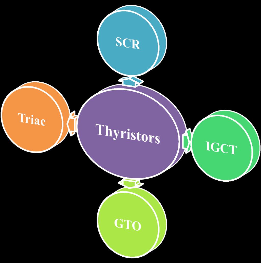
8 Thyristors 8


9 Thyristors ( Silicon Controlled Rectifiers SCRs ) Thyristors are electronic switches used in some power electronic circuits where control of switch turn-on is required. But once it turns ON, the control terminal becomes ineffective and the thyristor behaves similar to a diode. Thyristors are capable of large currents and large blocking voltages for use in high-power applications, but switching frequencies cannot be as high as when using other devices such as MOSFETs. The thyristor current, I A, flows from the anode (A) to the cathode (K) and the voltage V Ak across the thyristor is positive when the anode is at higher voltage than the cathode. 9


10 Thyristors ( Silicon Controlled Rectifiers SCRs ) In quadrant I, in the absence of a gate current, the device is OFF in the forward blocking region and supports a positive voltage. If a gate current is applied, the device switches to the ON-state region and the device has a i-v characteristic similar to that of a diode. In quadrant III, the device is OFF and the region is known as the reverse blocking region and supports a negative voltage. The characteristics are similar to those of a diode. Comparing the switching characteristics of a diode and a thyristor, it appears that when the thyristor is OFF, it can block large positive or negative voltage, which is a fundamental feature that is important in circuit applications. thyristor can be considered to carry an unidirectional current and supports a bidirectional voltage. 10
11 Thyristors ( Silicon Controlled Rectifiers SCRs ) Thyristors can only be turned on with three conditions: The device must be forward biased, i.e., the anode should be more positive than the cathode. A positive gate current (I g ) should be applied at the gate. The current through the thyristor should be more than the latching current. Once conducting,the anode current is LATCHED (continuously flowing). SCR rating Surge Current Rating (IFM) The surge current rating (IFM) of an SCR is the peak anode current an SCR can handle for a short duration. Holding Current (IL) A minimum anode current must flow through the SCR in order for it to stay ON initially after the gate signal is removed. This current is called the latching current (IL). Latching Current (IH) After the SCR is latched on, a certain minimum value of anode current is needed to maintain conduction. If the anode current is reduced below this minimum value, the SCR will turn OFF. Peak Repetitive Reverse Voltage (VRRM) The maximum instantaneous voltage that an SCR can withstand, without breakdown, in the reverse direction. Peak Repetitive Forward Blocking Voltage (VDRM) The maximum instantaneous voltage that the SCR can block in the forward direction. If the VDRM rating is exceeded, the SCR will conduct without a gate voltage. Nonrepetitive Peak Reverse Voltage (VRSM) The maximum transient reverse voltage that the SCR can withstand. Maximum Gate Trigger Current (IGTM) The maximum DC gate current allowed to turn the SCR ON. Minimum Gate Trigger Voltage (VGT) The minimum DC gate-to-cathode voltage required to trigger the SCR. Minimum Gate Trigger Current (IGT) The minimum DC gate current necessary to turn the SCR ON. 11
12 Thyristors ( Silicon Controlled Rectifiers SCRs ) Thyristor TURN-OFF Thyristor cannot be turned off by applying negative gate current. It can only be turned off if I A goes negative (reverse). This happens when negative portion of the of sine-wave occurs (natural commutation), Another method of turning off is known as forced commutation, The anode current is diverted to another circuitry. Types of Thyristors Phase controlled - Rectifying line frequency voltage and current for ac and dc motor drives. - Large voltage (up to 7kV) and current (up to 5kA) capability. - Low on-state voltage drop (1.5 to 3V). Inverter grade - Used in inverter and chopper. - Quite fast. Can be turned-on using force-commutation method. Light activated - Similar to phase controlled, but triggered by pulse of light. - Normally very high power ratings. TRIAC - Dual polarity thyristors. 12

 connected")


13 The Triac (triode for alternating current) The Triac is a member of the thyristor family which can conduct in both directions (bidirectional semi-controlled device). Thus a Triac is similar to two back to back (anti parallel) connected thyristosr but with only three terminals. The Triac extensively used in residential lamp dimmers, heater control and for speed control of small single phase series and induction motors. The conduction of a triac is initiated by injecting a current pulse into the gate terminal. The triac turns off only when the current through the main terminals become zero. As the Triac can conduct in both the directions the terms anode and cathode are not used for Triacs. The three terminals are marked as MT 1 (Main Terminal 1), MT 2 (Main Terminal 2) and the gate by G. 13


14 The Triac (triode for alternating current) Since a Triac is a bidirectional device and can have its terminals at various combinations of positive and negative voltages, there are four possible electrode potential combinations as given below MT 2 positive with respect to MT 1, G positive with respect to MT 1. MT 2 positive with respect to MT 1, G negative with respect to MT 1. MT 2 negative with respect to MT 1, G negative with respect to MT 1. MT 2 negative with respect to MT 1, G positive with respect to MT 1. In trigger mode-1 the gate current flows mainly through the P 2 N 2 junction like an ordinary thyristor. When the gate current has injected sufficient charge into P 2 layer the Triac starts conducting through the P 1 N 1 P 2 N 2 layers like an ordinary thyristor. 14
15 The Gate Turn-Off Thyristor (GTO) The GTO thyristor is a device that operates similar to a normal thyristor except the device physics, design and manufacturing features allow it to be turned-off by a negative gate current which is accomplished through the use of a bipolar transistor. Turning off is difficult. Need very large reverse gate current (normally 1/5 of anode current). I g I a A (Anode) + V ak _ K (Cathode) GTO: Symbol I a Gate drive design is very difficult due to very large reverse gate current at turn off. V r I h I bo I g >0 I g =0 Ratings: Highest power ratings switch: Voltage: V ak <5kV; Current: I a <5kA. Frequency<5KHz. V bo v-i characteristics V ak 15
 Ratings: Voltage: V ak <6.5kV; Current: I a <4kA. Frequency<1KHz. Currently 10kV device is being developed.")
16 Insulated Gate-Commutated Thyristor (IGCT) Conducts like normal thyristor (latching), but can be turned off using gate signal, similar to IGBT turn off; 20V is sufficent. I a Power switch is integrated with the gate-drive unit. I + V ak _ IGCT g K (Cathode) Ratings: Voltage: V ak <6.5kV; Current: I a <4kA. Frequency<1KHz. Currently 10kV device is being developed. Very low on state voltage: 2.7V for 4kA device 16


17 The MOS-Controlled Thyristor The MCT is a hybrid or double mechanism device that was designed to have a control port of a MOSFET and a power port of a thyristor. The characteristics of MCT are similar to the GTO, except that the gate drive circuitry for the MCT is less complicated than the design for a GTO as the control circuit of the MCT uses a MOSFET instead of a transistor. 17

18 Transistors 18


19 Bipolar Junction Transistor (BJT) For the npn-type BJT shown in fig. a, the Base (B) is the control terminal, where the power terminals are the Collector (C) and the Emitter (E). The real v-i characteristics of device are shown in fig. b. The device operates in quadrant I and is characterized by the plot of the collector current I C versus the collector to emitter voltage v CE as shown in fig. b. BJT is a current-controlled device. The device has three regions two of them where the device operates as a switch and the third is where the device operates as a linear amplifier. The device is OFF in the region below i B =0 and is ON in the region where v CE is less than v CE(Sat). Neglecting the middle region, the idealized device characteristics as a switch are shown in fig. c. During the ON state the device carries a collector current I C >0 with v CE =0. In the OFF-state, the device supports positive v CE >0 with I C = 0. Therefore, the BJT is unidirectional current and voltage device. 19
 and the power terminals are the Drain (D) and Source (S).")


20 The Metal Oxide Semiconductor Field Effect Transistor (MOSFET) For the n-channel MOSFET shown in fig. a, the control terminal known as the Gate (G) and the power terminals are the Drain (D) and Source (S). The device is controlled by supplying a voltage (v GS ) between the gate and the source. This makes it a voltage controlled device compared to the BJT, which is a current-controlled device. The real v-i characteristics of device are shown in fig. b. Similar to the BJT, the MOSFET operates within three operating regions. Two of the regions are used when the device is operated as a switch, and the third is when the device is used as an amplifier. To maintain the MOSFET in the off-state, v GS must be less than a threshold voltage known as v T, which is the region below the line marked OFF. And when the device is ON it act as resistance determined by the slope of the line marked ON. The idealized characteristics of a MOSFET switch are shown in fig. c. When the device is ON, it has zero v DS and carriers a current I D >0 and when the device is OFF it supports a positive v DS and has zero drain current (I D = 0). 20
 is a hybrid or also known as double mechanism device.")

 The control terminal is labeled as gate (G) and the power terminals are")


21 The Insulated Gate Bipolar Transistor (IGBT) The IGBT (its symbol shown in fig. a) is a hybrid or also known as double mechanism device. Its control port resembles a MOSFET and its output or power port resembles a BJT. Therefore, an IGBT combines the fast switching of a MOSFET and the low power conduction loss of a BJT. (b) The control terminal is labeled as gate (G) and the power terminals are labeled as collector (C) and emitter (E). The i-v characteristics of a real IGBT are shown in fig. b, which shows that the device operates in quadrants I and III. The ideal characteristics of the device are shown in fig. c. The device can block bidirectional voltage and conduct unidirectional current. An IGBT can change to the ON-state very fast but is slower than a MOSFET device. Discharging the gate capacitance completes control of the IGBT to the OFF-state. IGBT s are typically used for high power switching applications such as motor controls and for medium power PV and wind PE. 21
22 Comparison between GTO, IGCT and IGBT Item GTO IGCT IGBT Maximum switch power (V I ) 36MVA 36MVA 6MVA Active di/dt and dv/dt control No No Yes Active short circuit protection No No Yes Turn-off (dv/dt) snubber Required Not required No required Turn-on (di/dt) snubber Required Required No required Parallel connection No No Yes Switching speed Slow Moderate Fast Behavior after destruction Shorted Shorted Open in most cases On-state losses Low Low High Switching losses High Low Low Gate Driver Complex, Complex, Simple, separate integrated compact Gate Driver Power Consumption High High Low 22
23 Device Rating V (V) SCR 12000V/1500A (Mitsubishi) SCR: GTO/GCT: IGBT: 27MVA 36MVA 6MVA V/600A (Eupec) 4500V/900A (Mitsubishi) 6500V/1500A (Mitsubishi) 7500V/1650A (Eupec) 3300V/1200A (Eupec) GTO/GCT 2500V/1800A (Fuji) IGBT 6000V/3000A (ABB) 1700V/3600A (Eupec) 6500V/4200A (ABB) 4800V 5000A (Westcode) 6000V/6000A (Mitsubishi) I (A) 23


24 24
2 Marks - Question Bank. Unit 1- INTRODUCTION
 Two marks 1. What is power electronics? EE6503 POWER ELECTRONICS 2 Marks - Question Bank Unit 1- INTRODUCTION Power electronics is a subject that concerns the applications electronics principles into situations
Power Semiconductor Devices
 TRADEMARK OF INNOVATION Power Semiconductor Devices Introduction This technical article is dedicated to the review of the following power electronics devices which act as solid-state switches in the circuits.
UNIT I POWER SEMI-CONDUCTOR DEVICES
 UNIT I POWER SEMI-CONDUCTOR DEVICES SUBJECT CODE SUBJECT NAME STAFF NAME : EE6503 : Power Electronics : Ms.M.Uma Maheswari 1 SEMICONDUCTOR DEVICES POWER DIODE POWER TRANSISTORS POWER BJT POWER MOSFET IGBT
EEL 5245 POWER ELECTRONICS I Lecture #4: Chapter 2 Switching Concepts and Semiconductor Overview
 EEL 5245 POWER ELECTRONICS I Lecture #4: Chapter 2 Switching Concepts and Semiconductor Overview Objectives of Lecture Switch realizations Objective is to focus on terminal characteristics Blocking capability
Chapter 1 INTRODUCTION TO POWER ELECTRONICS SYSTEMS
 Chapter 1 INTRODUCTION TO POWER ELECTRONICS SYSTEMS Definition and concepts Application Power semiconductor switches Gate/base drivers Losses Snubbers 1 Definition of Power Electronics DEFINITION: To convert,
Learn about the use, operation and limitations of thyristors, particularly triacs, in power control
 Exotic Triacs: The Gate to Power Control Learn about the use, operation and limitations of thyristors, particularly triacs, in power control D. Mohan Kumar Modern power control systems use electronic devices
Switching and Semiconductor Switches
 1 Switching and Semiconductor Switches 1.1 POWER FLOW CONTROL BY SWITCHES The flow of electrical energy between a fixed voltage supply and a load is often controlled by interposing a controller, as shown
UNIVERSITY QUESTIONS. Unit-1 Introduction to Power Electronics
 UNIVERSITY QUESTIONS Unit-1 Introduction to Power Electronics 1. Give the symbol and characteristic features of the following devices. (i) SCR (ii) GTO (iii) TRIAC (iv) IGBT (v) SIT (June 2012) 2. What
POWER ELECTRONICS POWER ELECTRONICS INTRODUCTION TO. Dr. Adel Gastli. CONTENTS
 POWER ELECTRONICS INTRODUCTION TO POWER ELECTRONICS Dr. Adel Gastli Email: adel@gastli.net http://adel.gastli.net CONTENTS 1. Definitions and History 2. Applications of Power Electronics 3. Power Semiconductor
ELG4139: Power Electronics Systems Objective To Realize and Design Various Power Supplies and Motor Drives!
 ELG4139: Power Electronics Systems Objective To Realize and Design Various Power Supplies and Motor Drives! Power electronics refers to control and conversion of electrical power by power semiconductor
Prof. Steven S. Saliterman Introductory Medical Device Prototyping
 Introductory Medical Device Prototyping Department of Biomedical Engineering, University of Minnesota http://saliterman.umn.edu/ Solid state power switching: Silicon controlled rectifiers (SCR or Thyristor).
Teccor brand Thyristors AN1001
 A1001 Introduction The Thyristor family of semiconductors consists of several very useful devices. The most widely used of this family are silicon controlled rectifiers (SCRs), Triacs, SIDACs, and DIACs.
DOWNLOAD PDF POWER ELECTRONICS DEVICES DRIVERS AND APPLICATIONS
 Chapter 1 : Power Electronics Devices, Drivers, Applications, and Passive theinnatdunvilla.com - Google D Download Power Electronics: Devices, Drivers and Applications By B.W. Williams - Provides a wide
6. Explain control characteristics of GTO, MCT, SITH with the help of waveforms and circuit diagrams.
 POWER ELECTRONICS QUESTION BANK Unit 1: Introduction 1. Explain the control characteristics of SCR and GTO with circuit diagrams, and waveforms of control signal and output voltage. 2. Explain the different
AN1001. Fundamental Characteristics of Thyristors. Introduction. Basic Operation of a Triac. Basic Operation of an SCR. Basic Operation of a Diac
 A1001 Fundamental Characteristics of Thyristors 14 Introduction The thyristor family of semiconductors consists of several very useful devices. The most widely used of this family are silicon controlled
(anode) (also: I D, I F, I T )
 (also: I D, I F, I T )") (anode) V R - V A or V D or VF or V T IA (also: I D, I F, I T ) control terminals (e.g. gate for thyrisr; basis for BJT) - (IR =-I A ) (cathode) I A I F conducting range A p n K (a) V A (V F ) - A anode
(anode) V R - V A or V D or VF or V T IA (also: I D, I F, I T ) control terminals (e.g. gate for thyrisr; basis for BJT) - (IR =-I A ) (cathode) I A I F conducting range A p n K (a) V A (V F ) - A anode
UNIVERSITY OF TECHNOLOGY
 UNIVERSITY OF TECHNOLOGY Third Year DEPARTMENT OF ELECTRICAL ENGINEERING Electronics Engineering Section AC Machine and Power Electronics 2016-2017 Module-II: Power Electronics: Power electronics devices
Power semiconductors. José M. Cámara V 1.0
 Power semiconductors José M. Cámara V 1.0 Introduction Here we are going to study semiconductor devices used in power electronics. They work under medium and high currents and voltages. Some of them only
Electrical Engineering EE / EEE. Postal Correspondence Course. Power Electronics. GATE, IES & PSUs
 Power Electronics-EE GATE, IES, PSU 1 SAMPLE STUDY MATERIAL Electrical Engineering EE / EEE Postal Correspondence Course Power Electronics GATE, IES & PSUs Power Electronics-EE GATE, IES, PSU 2 C O N T
Power Electronics. Electrical Engineering. for
 Power Electronics for Electrical Engineering By www.thegateacademy.com Syllabus Syllabus for Power Electronics Characteristics of Semiconductor Power Devices: Diode, Thyristor, Triac, GTO, MOSFET, IGBT;
Lecture 23 Review of Emerging and Traditional Solid State Switches
 Lecture 23 Review of Emerging and Traditional Solid State Switches 1 A. Solid State Switches 1. Circuit conditions and circuit controlled switches A. Silicon Diode B. Silicon Carbide Diodes 2. Control
 http://www.electronics-tutorials.ws/power/triac.html Triac Tutorial and Basic Principles In the previous tutorial we looked at the construction and operation of the Silicon Controlled Rectifier more commonly
CHAPTER I INTRODUCTION
 CHAPTER I INTRODUCTION High performance semiconductor devices with better voltage and current handling capability are required in different fields like power electronics, computer and automation. Since
Power Electronics (BEG335EC )
") 1 Power Electronics (BEG335EC ) 2 PURWANCHAL UNIVERSITY V SEMESTER FINAL EXAMINATION - 2003 The figures in margin indicate full marks. Attempt any FIVE questions. Q. [1] [a] A single phase full converter
1 Power Electronics (BEG335EC ) 2 PURWANCHAL UNIVERSITY V SEMESTER FINAL EXAMINATION - 2003 The figures in margin indicate full marks. Attempt any FIVE questions. Q. [1] [a] A single phase full converter
Solid State Devices- Part- II. Module- IV
 Solid State Devices- Part- II Module- IV MOS Capacitor Two terminal MOS device MOS = Metal- Oxide- Semiconductor MOS capacitor - the heart of the MOSFET The MOS capacitor is used to induce charge at the
Dr.Arkan A.Hussein Power Electronics Fourth Class. Commutation of Thyristor-Based Circuits Part-I
 Commutation of Thyristor-Based Circuits Part-I ١ This lesson provides the reader the following: (i) (ii) (iii) (iv) Requirements to be satisfied for the successful turn-off of a SCR The turn-off groups
Introduction to Power Electronics BACKGROUND
 Department of Electrical Drives and Power Electronics Introduction to Power Electronics BACKGROUND Valery Vodovozov and Zoja Raud Tallinn 2010 Contents Preface... 3 Historical background... 4 Power electronic
Lecture Note on Switches Marc T. Thompson, 2003 Revised Use with gratefulness for ECE 3503 B term 2018 WPI Tan Zhang
 Lecture Note on Switches Marc T. Thompson, 2003 Revised 2007 Use with gratefulness for ECE 3503 B term 2018 WPI Tan Zhang Lecture note on switches_tan_thompsonpage 1 of 21 1. DEVICES OVERVIEW... 4 1.1.
Questions on JFET: 1) Which of the following component is a unipolar device?
 Which of the following component is a unipolar device?") Questions on JFET: 1) Which of the following component is a unipolar device? a) BJT b) FET c) DJT d) EFT 2) Current Conduction in FET takes place due e) Majority charge carriers only f) Minority charge
Questions on JFET: 1) Which of the following component is a unipolar device? a) BJT b) FET c) DJT d) EFT 2) Current Conduction in FET takes place due e) Majority charge carriers only f) Minority charge
3. Draw the two transistor model of a SCR and mention its applications. (MAY 2016)
") DHANALAKSHMI COLLEGE OF ENGINEERING DEPARTMENT OF ELECTRICAL AND ELECTRONICS ENGINEERING EE6503 POWER ELECTRONICS UNIT I- POWER SEMI-CONDUCTOR DEVICES PART - A 1. What is a SCR? A silicon-controlled rectifier
DHANALAKSHMI COLLEGE OF ENGINEERING DEPARTMENT OF ELECTRICAL AND ELECTRONICS ENGINEERING EE6503 POWER ELECTRONICS UNIT I- POWER SEMI-CONDUCTOR DEVICES PART - A 1. What is a SCR? A silicon-controlled rectifier
Power Electronics. Lecture No - 8
 Power Electronics Prof. B.G. Fernandes Department of Electrical Engineeringg Indian Institute of Technology, Bombay Lecture No - 8 Hello, in my last class we discussed the operation of bipolar junctionn
Lecture Switching Characteristics (Dynamic characteristics) Fig. 3.7 : Turn - on characteristics
 Fig. 3.7 : Turn - on characteristics") Lecture-14 3.4 Switching Characteristics (Dynamic characteristics) Thyristor Turn-ON Characteristics Fig. 3.7 : Turn - on characteristics When the SCR is turned on with the application of the gate signal,
Lecture-14 3.4 Switching Characteristics (Dynamic characteristics) Thyristor Turn-ON Characteristics Fig. 3.7 : Turn - on characteristics When the SCR is turned on with the application of the gate signal,
Pre-certification Electronics Questions. Answer the following with the MOST CORRECT answer.
 Electronics Questions Answer the following with the MOST CORRECT answer. 1. The cathode end terminal of a semiconductor diode can be identified by: a. the negative sign marked on the case b. a circular
Other Electronic Devices
 Other Electronic Devices 1 Contents Field-Effect Transistors(FETs) - JFETs - MOSFETs Insulate Gate Bipolar Transistors(IGBTs) H-bridge driver and PWM Silicon-Controlled Rectifiers(SCRs) TRIACs Device Selection
EPC2201 Power Electronic Devices Tutorial Sheet
 EPC2201 Power Electronic Devices Tutorial heet 1. The ON state forward voltage drop of the controlled static switch in Figure 1 is 2V. Its forward leakage current in the state is 2mA. It is operated with
Analog and Telecommunication Electronics
 Politecnico di Torino - ICT School Analog and Telecommunication Electronics F2 Active power devices»mos»bjt» IGBT, TRIAC» Safe Operating Area» Thermal analysis 30/05/2012-1 ATLCE - F2-2011 DDC Lesson F2:
Chapter 1 Power Electronic Devices
 Chapter 1 Power Electronic Devices Outline 1.1 An introductory overview of power electronic devices 1.2 Uncontrolled device power diode 1.3 Half- controlled device thyristor 1.4 Typical fully- controlled
Silicon Bidirectional Thyristors
 Preferred Device Silicon Bidirectional Thyristors Designed for high performance full-wave ac control applications where high noise immunity and high commutating di/dt are required. Blocking Voltage to
v D i D R Reverse blocking region Power Semiconductor Switches t rr Q rr Diodes Figure 1: A diode circuit Figure 2: i - v characteristics of a diode
 Power Semicductor Switches Diodes v D V rated R Reverse regi v D Figure 1: diode circuit Figure 2: i v characteristics of a diode Figure 3: Idealized characteristics of a diode v D t turn, the diode can
Battery Charger Circuit Using SCR
 Battery Charger Circuit Using SCR Introduction to SCR: SCR is abbreviation for Silicon Controlled Rectifier. SCR has three pins anode, cathode and gate as shown in the below figure. It is made up of there
EC 307 Power Electronics & Instrumentation
 EC 307 Power Electronics & Instrumentation MODULE I Difference Between Linear Electronics and Power Electronics Electronics has now become the core component in the development of the technology. The fast
NPSS Distinguished Lecturers Program
 NPSS Distinguished Lecturers Program Solid-state pulsed power on the move! Luis M. S. Redondo lmredondo@deea.isel.ipl.pt Lisbon Engineering Superior Institute (ISEL) Nuclear & Physics Center from Lisbon
POWER ELECTRONICS. Alpha. Science International Ltd. S.C. Tripathy. Oxford, U.K.
 POWER ELECTRONICS S.C. Tripathy Alpha Science International Ltd. Oxford, U.K. Contents Preface vii 1. SEMICONDUCTOR DIODE THEORY 1.1 1.1 Introduction 1.1 1.2 Charge Densities in a Doped Semiconductor 1.1
Dr.Arkan A.Hussein Power Electronics Fourth Class. Power Electronics
 Power Electronics ١ Introduction This lesson provides the reader the following: (i) (ii) (iii) (iv) (v) Create an awareness of the general nature of Power electronic equipment; Brief idea about topics
ELG3336: Power Electronics Systems Objective To Realize and Design Various Power Supplies and Motor Drives!
 ELG3336: Power Electronics Systems Objective To Realize and Design arious Power Supplies and Motor Drives! Power electronics refers to control and conversion of electrical power by power semiconductor
IFB270 Advanced Electronic Circuits
 IFB270 Advanced Electronic Circuits Chapter 11: Thyristors Prof. Manar Mohaisen Department of EEC Engineering Review of the Precedent Lecture To introduce several concepts on capacitance in amplifiers
DHANALAKSHMI COLLEGE OF ENGINEERING DEPARTMENT OF ELECTRICAL AND ELECTRONICS ENGINEERING
 DHANALAKSHMI COLLEGE OF ENGINEERING DEPARTMENT OF ELECTRICAL AND ELECTRONICS ENGINEERING Power Diode EE2301 POWER ELECTRONICS UNIT I POWER SEMICONDUCTOR DEVICES PART A 1. What is meant by fast recovery
Power Electronic Devices
 I ower Electronic Devices 1 ower Electronics Kaushik Rajashekara, Sohail Anwar, Vrej Barkhordarian, Alex Q. Huang Overview Diodes Schottky Diodes Thyristors ower Bipolar Junction Transistors MOSFETs General
POWER ELECTRONICS LAB MANUAL
 JIS College of Engineering (An Autonomous Institution) Department of Electrical Engineering POWER ELECTRONICS LAB MANUAL Exp-1. Study of characteristics of an SCR AIM: To obtain the V-I characteristics
Basic Electronics Prof. T.S. Natarajan Department of Physics Indian Institute of Technology, Madras
 Basic Electronics Prof. T.S. Natarajan Department of Physics Indian Institute of Technology, Madras Lecture 39 Silicon Controlled Rectifier (SCR) (Construction, characteristics (Dc & Ac), Applications,
BREAKDOWN DEVICES. Learning Objectives
 C H A P T E R64 Learning Objectives What are Breakdown Devices? Unijunction Transistor UJT Relaxation Oscillator Programmable UJT(PUT) Silicon Controlled Rectifier Comparison between Transistors and Thyristors
Power Electronics. Contents
 Power Electronics Overview Contents Electronic Devices Power, Electric, Magnetic circuits Rectifiers (1-ph, 3-ph) Converters, controlled rectifiers Inverters (1-ph, 3-ph) Power system harmonics Choppers
The Gate Turn-Off Thyristors (GTO) Part 2
 Part 2") The Gate Turn-Off Thyristors (GTO) Part 2 Static Characteristics On-state Characteristics: In the on-state the GTO operates in a similar manner to the thyristor. If the anode current remains above the
The Gate Turn-Off Thyristors (GTO) Part 2 Static Characteristics On-state Characteristics: In the on-state the GTO operates in a similar manner to the thyristor. If the anode current remains above the
MAC12HCDG, MAC12HCMG, MAC12HCNG
 MAC2HCDG, MAC2HCMG, MAC2HCNG Pb Description Designed primarily for full-wave ac control applications, such as motor controls, heating controls or dimmers; or wherever full wave, silicon gate controlled
SCR- SILICON CONTROLLED RECTIFIER
 SCR- SILICON CONTROLLED RECTIFIER Definition: When a pn junction is added to a junction transistor, the resulting three pn junction device is called a silicon controlled rectifier. SCR can change alternating
UNIT I POWER SEMICONDUCTOR DEVICES. Ref signal Control Digital Power Load Circuit Circuit Electronic circuit. Feedback Signal
 UNIT I POWER SEMICONDUCTOR DEICES The control of electric motor drives requires control of electric power. Power electronics have eased the concept of power control. Power electronics signifies the word
The silicon controlled rectifier (SCR)
") The silicon controlled rectifier (SCR) Shockley diodes are curious devices, but rather limited in application. Their usefulness may be expanded, however, by equipping them with another means of latching.
The silicon controlled rectifier (SCR) Shockley diodes are curious devices, but rather limited in application. Their usefulness may be expanded, however, by equipping them with another means of latching.
Power Electronics. P. T. Krein
 Power Electronics Day 10 Power Semiconductor Devices P. T. Krein Department of Electrical and Computer Engineering University of Illinois at Urbana-Champaign 2011 Philip T. Krein. All rights reserved.
600 V IL V IL4108 Zero Voltage Crossing Detector Triac Optocoupler
 FEATURES High Input Sensitivity I FT =.0 ma, PF=.0 I FT =.0 ma, PF.0 00 ma On-State Current Zero Voltage Crossing Detector 00/800 V Blocking Voltage High Static dv/dt 0 kv/µs Inverse Parallel SCRs Provide
Fundamentals of Power Semiconductor Devices
 В. Jayant Baliga Fundamentals of Power Semiconductor Devices 4y Spri ringer Contents Preface vii Chapter 1 Introduction 1 1.1 Ideal and Typical Power Switching Waveforms 3 1.2 Ideal and Typical Power Device
T12M50T600B TRIACS 12 AMPERES RMS 600 VOLTS. Triacs Sillicon Bidirectional Thyristors TO-220AB FEATURES MECHANICAL DATA
 LITE-ON SEMICONDUCTOR Triacs Sillicon Bidirectional Thyristors TRIACS 12 AMPERES RMS VOLTS FEATURES Blocking Voltage to Volts On-state Current Rating of 12 Amperes RMS at 9 Uniform Gate Trigger Currents
Unijunction Transistor. T.Y.B.Sc - Eletronics POWER ELETRONICS
 Unijunction Transistor T.Y.B.Sc - Eletronics POWER ELETRONICS Unijunction Transistor Symbol and Construction The Unijunction Transistor is solid state three terminal device that can be used in gate pulse,
VALLIAMMAI ENGINEERING COLLEGE DEPARTMENT OF ELECTRONICS AND INSTRUMENTATION
 VALLIAMMAI ENGINEERING COLLEGE DEPARTMENT OF ELECTRONICS AND INSTRUMENTATION Sem / Branch : V /EIE Subject code /Title: EI2301/Industrial Electronics UNIT-1 POWER DEVICES 1. What are the different methods
Application Note AN-3006 Optically Isolated Phase Controlling Circuit Solution
 www.fairchildsemi.com Application Note AN-3006 Optically Isolated Phase Controlling Circuit Solution Introduction Optocouplers simplify logic isolation from the ac line, power supply transformations, and
LENDI INSTITUTE OF ENGINEERING & TECHNOLOGY
 LENDI INSTITUTE OF ENGINEERING & TECHNOLOGY (Approved by A.I.C.T.E & Affiliated to JNTU,Kakinada) Jonnada (Village), Denkada (Mandal), Vizianagaram Dist 535 005 Phone No. 08922-241111, 241112 E-Mail: lendi_2008@yahoo.com
1200 V SiC Super Junction Transistors operating at 250 C with extremely low energy losses for power conversion applications
 1200 V SiC Super Junction Transistors operating at 250 C with extremely low energy losses for power conversion applications Ranbir Singh, Siddarth Sundaresan, Eric Lieser and Michael Digangi GeneSiC Semiconductor,
Power Devices and Circuits
 COURSE ON Power Devices and Circuits Master degree Electronic Curriculum Teacher: Prof. Dept. of Electronics and Telecommunication Eng. University of Napoli Federico II What is the scope of Power Electronics?
Semiconductors, ICs and Digital Fundamentals
 Semiconductors, ICs and Digital Fundamentals The Diode The semiconductor phenomena. Diode performance with ac and dc currents. Diode types: General purpose LED Zener The Diode The semiconductor phenomena
As you can see, by varying the turn-on point, the amount of power getting to the bulb is adjustable, and hence the light output can be controlled.
 Digital Light Dimming Circuit Some light dimmer history Light dimming is based on adjusting the voltage which gets to the lamp. Light dimming has been possible for many decades by using adjustable power
Today s subject MOSFET and IGBT
 Today s subject MOSFET and IGBT 2018-05-22 MOSFET metal oxide semiconductor field effect transistor Drain Gate n-channel Source p-channel The MOSFET - Source Gate G D n + p p n + S body body n - drift
Insulated Gate Bi-Polar Transistor Type T1600GB45G
 Date:- 1 Nov, 214 Data Sheet Issue:- 1 Insulated Gate Bi-Polar Transistor Type Absolute Maximum Ratings VOLTAGE RATINGS MAXIMUM LIMITS V CES Collector emitter voltage 45 V V DC link Permanent DC voltage
Power Electronics (Sample Questions) Module-1
 Module-1") Module-1 Short Questions (Previous Years BPUT Questions 1 to 18) 1. What are the conditions for a thyristor to conduct? di 2. What is the common method used for protection? dt 3. What is the importance
Module-1 Short Questions (Previous Years BPUT Questions 1 to 18) 1. What are the conditions for a thyristor to conduct? di 2. What is the common method used for protection? dt 3. What is the importance
The two-in-one chip. The bimode insulated-gate transistor (BIGT)
") The two-in-one chip The bimode insulated-gate transistor (BIGT) Munaf Rahimo, Liutauras Storasta, Chiara Corvasce, Arnost Kopta Power semiconductor devices employed in voltage source converter (VSC) applications
The two-in-one chip The bimode insulated-gate transistor (BIGT) Munaf Rahimo, Liutauras Storasta, Chiara Corvasce, Arnost Kopta Power semiconductor devices employed in voltage source converter (VSC) applications
(250 Volts Peak) COUPLER SCHEMATIC. MAXIMUM RATINGS (TA = 25 C unless otherwise noted) Rating Symbol Value Unit STYLE 6 PLASTIC
 COUPLER SCHEMATIC. MAXIMUM RATINGS (TA = 25 C unless otherwise noted) Rating Symbol Value Unit STYLE 6 PLASTIC") (0 Volts Peak) The Series consists of gallium arsenide infrared emitting diodes, optically coupled to silicon bilateral switch and are designed for applications requiring isolated triac triggering, low
(0 Volts Peak) The Series consists of gallium arsenide infrared emitting diodes, optically coupled to silicon bilateral switch and are designed for applications requiring isolated triac triggering, low
Experiment (1) Principles of Switching
 Principles of Switching") Experiment (1) Principles of Switching Introduction When you use microcontrollers, sometimes you need to control devices that requires more electrical current than a microcontroller can supply; for this,
Experiment (1) Principles of Switching Introduction When you use microcontrollers, sometimes you need to control devices that requires more electrical current than a microcontroller can supply; for this,
T12M5T-B SERIES TRIACS 12 AMPERES RMS 600 VOLTS. Sensitive Gate Triacs Sillicon Bidirectional Thyristors FEATURES TO-220AB MECHANICAL DATA
 LITE-ON SEMICONDUCTOR Sensitive Gate Triacs Sillicon Bidirectional Thyristors TRIACS 2 AMPERES RMS 600 VOLTS FEATURES Sensitive Gate Allows Triggering by Microcontrollers and other Blocking Voltage to
INSTITUTE OF AERONAUTICAL ENGINEERING (Autonomous) Dundigal, Hyderabad
 Dundigal, Hyderabad") I INSTITUTE OF AERONAUTICAL ENGINEERING (Autonomous) Dundigal, Hyderabad-000 DEPARTMENT OF ELECTRICAL AND ELECTRONICS ENGINEERING TUTORIAL QUESTION BANK Course Name : POWER ELECTRONICS Course Code : AEE0
I INSTITUTE OF AERONAUTICAL ENGINEERING (Autonomous) Dundigal, Hyderabad-000 DEPARTMENT OF ELECTRICAL AND ELECTRONICS ENGINEERING TUTORIAL QUESTION BANK Course Name : POWER ELECTRONICS Course Code : AEE0
Lecture 2 - Overview of power switching devices. The Power Switch: what is a good power switch?
 Lecture 2 - Overview of power switching devices The Power Switch: what is a good power switch? A K G Attributes of a good power switch are: 1. No power loss when ON 2. No power loss when OFF 3. No power
Analysis on IGBT Developments
 Analysis on IGBT Developments Mahato G.C., Niranjan and Waquar Aarif Abu RVS College of Engineering and Technology, Jamshedpur India Abstract Silicon based high power devices continue to play an important
T8M35T-B SERIES TRIACS 8 AMPERES RMS 600 VOLTS. Triacs Sillicon Bidirectional Thyristors TO-220AB FEATURES MECHANICAL DATA
 LITE-ON SEMICONDUCTOR Triacs Sillicon Bidirectional Thyristors TRIACS 8 AMPERES RMS 600 VOLTS FEATURES Blocking Voltage to 600 Volts On-State Current Rating of 8.0 Amperes RMS at 0 Uniform Gate Trigger
List of Experiments. 1. Steady state characteristics of SCR, IGBT and MOSFET. (Single phase half wave rectifier). (Simulation and hardware).
. (Simulation and hardware).") (Scheme-2013) List of Experiments 1. Steady state characteristics of SCR, IGBT and MOSFET 2. nalog and digital firing methods for SCR (Single phase half wave rectifier). (Simulation and hardware). 3. Full
(Scheme-2013) List of Experiments 1. Steady state characteristics of SCR, IGBT and MOSFET 2. nalog and digital firing methods for SCR (Single phase half wave rectifier). (Simulation and hardware). 3. Full
ECE1750, Spring Week 1 - Components
 ECE1750, Spring 2018 Week 1 - Components 1 Most commonly used power electronic switches: Diodes(aka (a.k.a. rectifiers) Thyristors (a.k.a. silicon controlled rectifiers, SCRs) Power MOSFETs IGBTs 2 But
MCR8NG. Thyristors. Surface Mount 600V - 800V > MCR8NG. Description
 Pb Description Designed primarily for half-wave ac control applications, such as motor controls, heating controls, and power supplies; or wherever half wave, silicon gate controlled devices are needed.
Theory and Applications (Chapters 1 thru 9) Selector Guide. Data Sheets. Surface Mount Package Information and Tape and Reel Specifications
 Selector Guide. Data Sheets. Surface Mount Package Information and Tape and Reel Specifications") Theory and Applications (Chapters 1 thru 9) 1 Selector Guide Data Sheets 3 Surface Mount Package Information and Tape and Reel Specifications 4 Outline Dimensions and Leadform Options 5 Index and Cross
Theory and Applications (Chapters 1 thru 9) 1 Selector Guide Data Sheets 3 Surface Mount Package Information and Tape and Reel Specifications 4 Outline Dimensions and Leadform Options 5 Index and Cross
CHAPTER 1 INTRODUCTION
 1 CHAPTER 1 INTRODUCTION 1.1 GENERAL Induction motor drives with squirrel cage type machines have been the workhorse in industry for variable-speed applications in wide power range that covers from fractional
provide excellent noise immunity, short delay times and simple gate drive. The intrinsic chip gate resistance and capacitance of the APT80GA60LD40
 APT8GA6LD 6V High Speed PT IGBT POWER MOS 8 is a high speed Punch-Through switch-mode IGBT. Low E off is achieved through leading technology silicon design and lifetime control processes. A reduced E off
2N6504 Series. Silicon Controlled Rectifiers. Reverse Blocking Thyristors. SCRs 25 AMPERES RMS 50 thru 800 VOLTS
 Preferred Device Silicon Controlled Rectifiers Reverse Blocking Thyristors Designed primarily for half-wave ac control applications, such as motor controls, heating controls and power supply crowbar circuits.
Field Effect Transistors (npn)
") Field Effect Transistors (npn) gate drain source FET 3 terminal device channel e - current from source to drain controlled by the electric field generated by the gate base collector emitter BJT 3 terminal
Field Effect Transistors (npn) gate drain source FET 3 terminal device channel e - current from source to drain controlled by the electric field generated by the gate base collector emitter BJT 3 terminal
T1235T-8R. 12 A Snubberless Triac. Description. Features. Applications
 12 A Snubberless Triac Datasheet - production data Features A2 G I²PAK 12 A medium current Triac Three triggering quadrants device Very high noise immunity and dynamic commutation ECOPACK 2 compliant component
CHOICE OF HIGH FREQUENCY INVERTERS AND SEMICONDUCTOR SWITCHES
 Chapter-3 CHOICE OF HIGH FREQUENCY INVERTERS AND SEMICONDUCTOR SWITCHES This chapter is based on the published articles, 1. Nitai Pal, Pradip Kumar Sadhu, Dola Sinha and Atanu Bandyopadhyay, Selection
1 Basics V GG. V GS(th) V GE(th) , i C. i D I L. v DS. , v CE V DD V CC. V DS(on) VCE(sat) (IGBT) I t MOSFET MOSFET.
 V GE(th) , i C. i D I L. v DS. , v CE V DD V CC. V DS(on) VCE(sat) (IGBT) I t MOSFET MOSFET.") Reverse operation During reverse operation (Figure 1.10, III rd quadrant) the IGBT collector pn-junction is poled in reverse direction and there is no inverse conductivity, other than with MOSFETs. Although,
Reverse operation During reverse operation (Figure 1.10, III rd quadrant) the IGBT collector pn-junction is poled in reverse direction and there is no inverse conductivity, other than with MOSFETs. Although,
T835T-8I. 8 A Snubberless Triac
 8 A Snubberless Triac Datasheet - production data Features High static dv/dt High dynamic commutation 150 C maximum Tj Three quadrants Built-in ceramic for tab insulation Compliance to UL1557 standard
IGBTs (Insulated Gate Bipolar Transistor)
") IGBTs (Insulated Gate Bipolar Transistor) Description This document describes the basic structures, ratings, and electrical characteristics of IGBTs. It also provides usage considerations for IGBTs. 1
IGBTs (Insulated Gate Bipolar Transistor) Description This document describes the basic structures, ratings, and electrical characteristics of IGBTs. It also provides usage considerations for IGBTs. 1
3 Hints for application
 i RG i G i M1 v E M1 v GE R 1 R Sense Figure 3.59 Short-circuit current limitation by reduction of gate-emitter voltage This protection technique limits the stationary short-circuit current to about three
Digital Electronics. By: FARHAD FARADJI, Ph.D. Assistant Professor, Electrical and Computer Engineering, K. N. Toosi University of Technology
 K. N. Toosi University of Technology Chapter 7. Field-Effect Transistors By: FARHAD FARADJI, Ph.D. Assistant Professor, Electrical and Computer Engineering, K. N. Toosi University of Technology http://wp.kntu.ac.ir/faradji/digitalelectronics.htm
(a) average output voltage (b) average output current (c) average and rms values of SCR current and (d) input power factor. [16]
![(a) average output voltage (b) average output current (c) average and rms values of SCR current and (d) input power factor. [16]](/thumbs/81/83006678.jpg "(a) average output voltage (b) average output current (c) average and rms values of SCR current and (d) input power factor. [16]") Code No: 07A50204 R07 Set No. 2 1. A single phase fully controlled bridge converter is operated from 230 v, 50 Hz source. The load consists of 10Ω and a large inductance so as to reach the load current
Code No: 07A50204 R07 Set No. 2 1. A single phase fully controlled bridge converter is operated from 230 v, 50 Hz source. The load consists of 10Ω and a large inductance so as to reach the load current
Features TO-264 E. Symbol Description SGL50N60RUFD Units V CES Collector-Emitter Voltage 600 V V GES Gate-Emitter Voltage ± 20 V Collector T
 Short Circuit Rated IGBT General Description Fairchild's RUFD series of Insulated Gate Bipolar Transistors (IGBTs) provide low conduction and switching losses as well as short circuit ruggedness. The RUFD
Optimization of High Voltage IGCTs towards 1V On-State Losses
 Optimization of High Voltage IGCTs towards 1V On-State Losses Munaf Rahimo, Martin Arnold, Umamaheswara Vemulapati, Thomas Stiasny ABB Switzerland Ltd, Semiconductors, munaf.rahimo@ch.abb.com Abstract
Semiconductor analyser AS4002P User Manual
 Semiconductor analyser AS4002P User Manual Copyright Ormelabs (C) 2010 http://www.ormelabs.com 1 CONTENTS SECTION Page SECTION 1: Introduction... 3 SECTION 2: Features... 3 SECTION 3: Component analysis...
CCSTA53N30A10. Solidtron TM N-Type Semiconductor Discharge Switch, ThinPak TM. ThinPak TM. 275 Great Valley Parkway Malvern, PA Ph:
 Description Package Size - 9 This current controlled (CCS) discharge switch is an n-type Thyristor in a high performance ThinPak TM package. The device gate is similar to that found on a traditional GTO