ARNSW Balun Day. Balun construction
|
|
|
- Brianne Poole
- 6 years ago
- Views:
Transcription

1 ARNSW Balun Day Balun construction


2 Typical Baluns All built from locally available components.
3 Balun uses Most baluns are used to match the 50Ω output of a transceiver to an antenna. A centre fed dipole should have a 1:1 balun to ensure any unbalance in the two halves does not result in radiation from the coaxial line. Some antennas require matching to 200Ω and thus a 4:1 balun is required. Today the focus will be on 1:1 and 4:1 baluns as these are available in kit form.
4 Balun design Baluns are NOT transformers in the classical sense of two windings coupled by a magnetic core. A balun could be made as a transformer but the performance would be disappointing. The leakage inductance (this is a measure of the coupling of the two windings) and the inter-winding capacitance would limit the bandwidth of the transformer. Winding techniques to reduce these limitations are complex and large magnetic cores are required to support 100s to 1000s of watts of RF power.
5 Balun performance requirements. Wide bandwidth 1.5 to 30MHz or more Low loss. When running at 1kW the loss must be low or else the core will overheat. Simple to build. Available components. All this can be met by using a transmission line transformer.
6 Transmission line transformers For 50Ω 1:1 Baluns the transmission line must be 50Ω. This can be coaxial cable or a bifilar parallel transmission line. Two types of transmission line transformer have been shown to be efficient at HF. The Current balun described by Guanella in professional literature The Voltage balun described by Ruthroff. Of these two the current balun is simple to construct and has excellent performance.
7 The 1:1 current balun. For 1:1 50Ω baluns the Guanella current balun can be shown to be superior to all other more complex designs. The required function of a 1:1 balun is to pass the desired differential RF current while blocking common mode current caused by an out of balance load. All that is required to do this efficiently is enough common reactance on the inner and outer conductors of a coaxial line or the two conductors of a parallel line.
8 Toroid Baluns Winding the line on a low permeability ferrite toroid is an effective method. Permeability should be 125 to 250 to give high common mode inductance without losses in the ferrite if there should be an unbalanced load. RG316 coax can handle high power at HF and is small enough to fit on a 40mm toroid.

9 Toroid Baluns What Core Material? Micro Metals T200-2 Iron Powder Core. Permeability (ui) = 10. Iron powder is suitable for baluns from about 7MHz to 50MHz but does not have enough permeability to ensure sufficient inductance for below 7MHz. Micro Metals FT Nickel zinc ferrite. Permeability (ui) = 125. Ferrite is suitable for baluns from about 1MHz to 30MHz due to the higher permeability thus ensuring sufficient inductance for below 7MHz. Permeability above 250 is not recommended as this will degrade high frequency performance.

10 Toroid Balun Construction This is about as simple as possible Wind the coax around the toroid and half way cross over back to the start and wind the second half of the total winding. This method ensures the start and finish are at opposite ends.

11 Cannot buy RG316? Use 2 parallel 1.25mm enamelled copper wires This is approximately a 50Ω transmission line. The same winding method with the crossover can be used to place the start and finish on opposite sided of the toroid.
12 What about 3 winding baluns Why the third winding? This winding is wound as an extra winding physically separate to the transmission line but on the same core. Called a compensating winding but does not seem to improve performance. At low frequencies couples energy into the core and is of such high reactance at high frequencies to be ineffective. Conclusion is it is not required and may degrade performance
13 1:1 Balun conclusion The current balun is simple and can be shown to be effective. Either coax or parallel wire 50Ω transmission line can be used. 10 to 15 turns on a permeability 125 core works over 3 to 30MHz More turns or higher permeability core will allow operation down to 1.8MHz.
14 1:4 Balun As the transformation is 50Ω to 200Ω the transmission line must be 100Ω. Two Guanella transmission line transformers can be connected in parallel on the 50Ω side and in series on the 200Ω side to form the balun. 100Ω can be made from 1.25mm wire with 2.0mm heat shrink as the insulator.
15 1:4 balun schematic. Two transformer cores Single transformer core


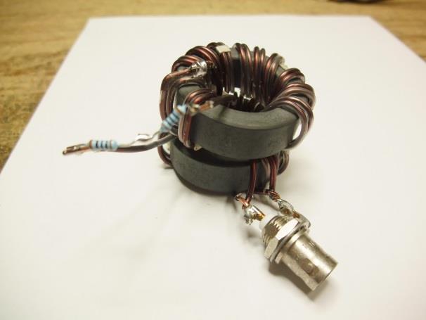
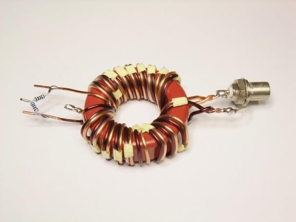
16 Example 1:4 Baluns The two transmission line transformers are wound on the same core. In this example the two transformers are wound on separate cores to allow for more turns per transformer

17 Ruthroff 1:4 Balun This is a simpler 1:4 balun with reduced performance over the Guanella balun but still satisfactory over the 3 to 30MHz range.

18 Ruthroff 1:4 Balun Schematic Uses a 100Ω transmission line transformer to provide a 1:4 impedance step up. Only suitable for a well balanced 200 ohm load.
19 Do These Baluns Work? Two measurements demonstrated that the balun is effective. 1. Place a load on the output 50Ω for a 1:1 and 200Ω for the 4:1. Measure the input impedance across 1 to 50MHz. The impedance should be 50Ω resistive with very little reactance at 30MHz. 2. While measuring the impedance short one output at a time to the input ground and the impedance should not change. This demonstrates the balun is converting the unbalanced input to a balanced output.


20 Todays Kits TetEmtron 4:1 Balun Kit TetEmtron 1:1 Balun Kit

21 Completed 4:1 Balun

22 Completed 1:1 Balun
and Related Topics W7KVI, HARC Original: 3/26/16
 Baluns, Ununs, and Related Topics W7KVI, HARC Original: 3/26/16 This Presentation Informal & brisk - 52 slides (too many unless you re an enthusiast!) Discussion encouraged if not extensive, interrupt
The design of Ruthroff broadband voltage transformers M. Ehrenfried G8JNJ
 The design of Ruthroff broadband voltage transformers M. Ehrenfried G8JNJ Introduction I started investigating balun construction as a result of various observations I made whilst building HF antennas.
What is a BALUN or UNUN:
 What is a BALUN or UNUN: A device to connect different types of antennas to various feed lines. Can transform impedances, choke common mode or change balanced to unbalanced BALUN Balanced to Unbalanced
Free ferrite from TV sets in BALUN use
 Free ferrite from TV sets in BALUN use JK De Marco, PY2WM 18/jan/2006, revised on 2/April/2009 After an article by Ian White, G3SEK, in RadCom magazine, suggesting the use of ferrite removed from deflection
1) Transmission Line Transformer a. First appeared on the scene in 1944 in a paper by George Guanella as a transmission line transformer, the 1:1
 Transmission Line Transformer a. First appeared on the scene in 1944 in a paper by George Guanella as a transmission line transformer, the 1:1") 1) Transmission Line Transformer a. First appeared on the scene in 1944 in a paper by George Guanella as a transmission line transformer, the 1:1 Guanella Balun is the basic building Balun building block.
1) Transmission Line Transformer a. First appeared on the scene in 1944 in a paper by George Guanella as a transmission line transformer, the 1:1 Guanella Balun is the basic building Balun building block.
WCARES NEEDS YOU! CONSIDER MAKING A TECHNICAL PRESENTATION AT AN UPCOMING CHEW & CHAT MEETING LEARN SOMETHING NEW AND PRESENT
 WCARES NEEDS YOU! CONSIDER MAKING A TECHNICAL PRESENTATION AT AN UPCOMING CHEW & CHAT MEETING SHARE WHAT YOU KNOW LEARN SOMETHING NEW AND PRESENT IT CONTACT TIM AD4CJ AD4CJ@arrl.net 1 Transmission Line
Jacques Audet VE2AZX. Nov VE2AZX 1
 Jacques Audet VE2AZX VE2AZX@amsat.org Nov. 2006 VE2AZX 1 - REASONS FOR USING A BALUN - TYPES OF BALUNS - CHECK YOUR BALUN WITH AN SWR ANALYZER - MEASURING THE IMPEDANCE OF A NUMBER OF FERRITES - IMPEDANCE
The Balun and The UNUN - page 1
 The Balun and The UNUN - page 1 When is a Balun, not a balun, when it is an UNUN! Balun = "BALanced-to-UNbalanced" Unun = "UNbalanced-to-UNbalanced" Looking at the two diagrams above you will see the common
The Balun and The UnUn - page 1
 The Balun and The UnUn - page 1 When is a Balun, not a Balun, when it is an UnUn! Balun = "Balanced-to-Unbalanced" UnUn = "Unbalanced-to-Unbalanced" Looking at the two diagrams above you will see the common
A TRANSMISSION LINE BALANCE TEST METER
 by Lloyd Butler VK5BR with modifications by Phil Storr VK5SRP. Here is a simple meter to check the balance of currents running in the two legs of a transmission line. It can be used to check the balance
Owen Duffy VK2OMD owenduffy.net
 Owen Duffy VK2OMD owenduffy.net owen@owenduffy.net Antenna system Differential and common mode feed line current Balun types and characteristics Insights from NEC models, measurements Example application:
Transmission Line Signal Sampling By Don Steinbach, AE6PM
 Transmission Line Signal Sampling By Don Steinbach, AE6PM When I was finalizing the mechanical layout of my remotely-operated 3-position coaxial antenna switch (Fig. 1), I wanted to include a way to bring
Coaxial Transmitting Chokes. Don t Bother Taking Notes
 Coaxial Transmitting Chokes Jim Brown K9YC Santa Cruz, CA http://audiosystemsgroup.com Don t Bother Taking Notes These slides (and a lot more) are at http://audiosystemsgroup.com\publish.htm 1 Why Do We
WHY YOU NEED A CURRENT BALUN
 HF OPERATORS WHY YOU NEED A CURRENT BALUN by John White VA7JW NSARC HF Operators 1 What is a Balun? A BALUN is a device typically inserted at the feed point of a dipole-like antenna wire dipoles, Yagi
A short, off-center fed dipole for 40 m and 20 m by Daniel Marks, KW4TI
 A short, off-center fed dipole for 40 m and 20 m by Daniel Marks, KW4TI Version 2017-Nov-7 Abstract: This antenna is a 20 to 25 foot long (6.0 m to 7.6 m) off-center fed dipole antenna for the 20 m and
End Fed Half Wave Antenna Coupler
 End Fed Half Wave Antenna Coupler The finished End Fed Half Wave antenna coupler. Centre fed half wave dipoles make great, simple and effective antennas for the HF bands. Sometimes however, the centre
Intermediate Course (5) Antennas and Feeders
 Antennas and Feeders") Intermediate Course (5) Antennas and Feeders 1 System Transmitter 50 Ohms Output Standing Wave Ratio Meter Antenna Matching Unit Feeder Antenna Receiver 2 Feeders Feeder types: Coaxial, Twin Conductors
Intermediate Course (5) Antennas and Feeders 1 System Transmitter 50 Ohms Output Standing Wave Ratio Meter Antenna Matching Unit Feeder Antenna Receiver 2 Feeders Feeder types: Coaxial, Twin Conductors
Milton Keynes Amateur Radio Society (MKARS)
") Milton Keynes Amateur Radio Society (MKARS) Intermediate Licence Course Feeders Antennas Matching (Worksheets 31, 32 & 33) MKARS Intermediate Licence Course - Worksheet 31 32 33 Antennas Feeders Matching
Milton Keynes Amateur Radio Society (MKARS) Intermediate Licence Course Feeders Antennas Matching (Worksheets 31, 32 & 33) MKARS Intermediate Licence Course - Worksheet 31 32 33 Antennas Feeders Matching
What causes the Out-of-Balance Current in the coax and why does it Radiate?
 The EH Antenna - Out of Balance Current or Longitudinal Mode Current in the Coaxial Cable causes radiation from the coax. But how large a proportion of the total power is radiated or lost from this Current?
Design Considerations
 Design Considerations APPLICATION NOTES: Multi-hole cores provide specialized shapes that are sometimes more useful than single hole devices. One example is wide band transformers where good coupling between
A Transmatch for Balanced or Unbalanced Lines
 A Transmatch for Balanced or Unbalanced Lines Most modern transmitters are designed to operate into loads of approximately 50 Ω. Solid-state transmitters produce progressively lower output power as the
db = 10 log10 (P1/P2) where P1 and P2 are two power levels
 where P1 and P2 are two power levels") A Quick Introduction to Decibels (db) Unit is the Bel: named after A.G. Bell who devised it for his work with deafness and audio sound levels. Now used for all frequencies of AC power. Decibel (db): -1
A Quick Introduction to Decibels (db) Unit is the Bel: named after A.G. Bell who devised it for his work with deafness and audio sound levels. Now used for all frequencies of AC power. Decibel (db): -1
Antenna Design for FM-02
 Antenna Design for FM-02 I recently received my FM-02 FM transmitter which I purchased from WLC. I researched the forum on what antennas where being used by the DIY community and found a nice write-up
Application of Soft Ferrite Material: from EMC to RFID
 Application of Soft Ferrite Material: from EMC to RFID 26 April 2012 Alan Keenan Industrial Electronics GmbH in partnership with HF Technology & Fair-Rite Products Corp. www.fair-rite.com www.ie4u.eu Topics
Cray Valley Radio Society. Real Life Wire Antennas
 Cray Valley Radio Society Real Life Wire Antennas 1 The basic dipole The size of an antenna is determined by the wavelength of operation In free space: ~3x10 8 m/s Frequency x Wavelength = Speed of Light,
Least understood topics by most HAMs RF Safety Ground Antennas Matching & Feed Lines
 Least understood topics by most HAMs RF Safety Ground Antennas Matching & Feed Lines Remember this question from the General License Exam? G0A03 (D) How can you determine that your station complies with
One I had narrowed the options down, I installed some wire and started testing.
 Loft & Attic antennas for restricted spaces - M. Ehrenfried G8JNJ I ve recently been looking at designs for an efficient antenna that would fit in a loft. I hoped to find something that would work on with
Chokes and Isolation Transformers For Receiving Antennas By Jim Brown K9YC 2018 by James W. Brown All rights reserved
 Chokes and Isolation Transformers For Receiving Antennas By Jim Brown K9YC 2018 by James W. Brown All rights reserved Why We Need Them A feedline must be grounded where it enters the shack-for lightning
COAXIAL TRANSMISSION LINE COMMON-MODE CURRENT
 COAXIAL TRANSMISSION LINE COMMON-MODE CURRENT Introduction Coaxial transmission lines are popular for their wide frequency bandwidth and high resistance to electromagnetic interference (EMI). Coax cables
Basic Wire Antennas. Part II: Loops and Verticals
 Basic Wire Antennas Part II: Loops and Verticals A loop antenna is composed of a single loop of wire, greater than a half wavelength long. The loop does not have to be any particular shape. RF power can
FBK portable mini tuner
 FBK portable mini tuner tunes symmetric/coax/longwire antenna's between 1.8-50MHz When possible it is always preferred to use a full sized antenna, especially when using low powered portable transceivers
Some hints/tips on how to assemble nice COAX TRAPS!
 Some hints/tips on how to assemble nice COAX TRAPS! Before we start to assemble our traps, here some general info as introduction : Coax traps are cheap, easy to assemble in a reproducible manner, very
How to Blow Up Your Balun
 How to Blow Up Your Balun (and other things too ) By Dean Straw, N6BV Sea-Pac June 7, 2014 Photos courtesy Jim Brown, K9YC 1 This is What I Intend to do Today I will examine stresses placed on common-mode
ECE Microwave Engineering
 ECE 5317-6351 Microwave Engineering Adapted from notes by Prof. Jeffery T. Williams Fall 2018 Prof. David R. Jackson Dept. of ECE Notes 4 Transmission Lines Part 3: Baluns 1 Baluns Baluns are used to connect
Investigation of the Double-Y Balun for Feeding Pulsed Antennas
 Proceedings of the SPIE, Vol. 5089, April 2003 Investigation of the Double-Y Balun for Feeding Pulsed Antennas Jaikrishna B. Venkatesan a and Waymond R. Scott, Jr. b Georgia Institute of Technology Atlanta,
Dipole Antennas. Prof. Girish Kumar Electrical Engineering Department, IIT Bombay. (022)
") Dipole Antennas Prof. Girish Kumar Electrical Engineering Department, IIT Bombay gkumar@ee.iitb.ac.in (022) 2576 7436 Infinitesimal Dipole An infinitesimally small current element is called the Hertz Dipole
Dipole Antennas Prof. Girish Kumar Electrical Engineering Department, IIT Bombay gkumar@ee.iitb.ac.in (022) 2576 7436 Infinitesimal Dipole An infinitesimally small current element is called the Hertz Dipole
A Note About I try to answer your promptly, but...
 You ve got to see our web site! Join the fun at - http://www.radioworks.com New! Full Catalog On-line Now you can download the latest issue of our General Catalog and any forthcoming special interest catalogs.
Master Thesis. Mobile Phone Antenna Modelling. Umut Bulus. Supervised by Prof. Dr.-Ing. K. Solbach
 Master Thesis Mobile Phone Antenna Modelling Umut Bulus Supervised by Prof. Dr.-Ing. K. Solbach 2.3.28 Contents Introduction Theoretical Background Antenna Measurements on Different PCB Variations Investigation
EVERY rotor control, remote antenna selector also has a common mode choke at each end of the cable!
 Radio Communication Choosing a Coax Feed Line Choke By Bob Brehm, AK6R RFI Tip Sheet #RC-1 How to choose feed line chokes, line isolators, baluns, or ununs for coax fed dipoles, verticals, hex beams, slopers,
The Fabulous Dipole. Ham Radio s Most Versatile Antenna
 The Fabulous Dipole Ham Radio s Most Versatile Antenna 1 What is a Dipole? Gets its name from its two halves One leg on each side of center Each leg is the same length It s a balanced antenna The voltages
Antenna? What s That? Chet Thayer WA3I
 Antenna? What s That? Chet Thayer WA3I Space: The Final Frontier Empty Space (-Time) Four dimensional region that holds everything Is Permeable : It requires energy to set up a magnetic field within it.
160- and 80-Meter Matching Networks for your 43-foot Vertical Phil Salas AD5X
 160- and 80-Meter Matching Networks for your 43-foot Vertical Phil Salas AD5X 43-foot verticals have become popular as they can be self supporting, are not too obtrusive, and have higher radiation resistance
MFJ-219/219N 440 MHz UHF SWR Analyzer TABLE OF CONTENTS
 MFJ-219/219N 440 MHz UHF SWR Analyzer TABLE OF CONTENTS Introduction...2 Powering The MFJ-219/219N...3 Battery Installation...3 Operation Of The MFJ-219/219N...4 SWR and the MFJ-219/219N...4 Measuring
Iron Powder Core Selection For RF Power Applications. Jim Cox Micrometals, Inc. Anaheim, CA
 HOME APPLICATION NOTES Iron Powder Core Selection For RF Power Applications Jim Cox Micrometals, Inc. Anaheim, CA Purpose: The purpose of this article is to present new information that will allow the
Feed Line Currents for Neophytes.
 Feed Line Currents for Neophytes. This paper discusses the sources of feed line currents and the methods used to control them. During the course of this paper two sources of feed line currents are discussed:
The Impedance-Transformation Properties of Common 4:1 Balun Types Part 1: Essential Background. L. B. Cebik, W4RNL
 The Impedance-Transformation Properties of Common 4:1 Balun Types Part 1: Essential Background L. B. Cebik, W4RNL One of the most ubiquitous antenna-system accessories among radio amateurs is the 4:1 balun.
Ten-Tec Orion Sub Receiver VHF Filter Modification Prepared by Rick Williams, VE7TK
 Ten-Tec Orion Sub Receiver VHF Filter Modification Prepared by Rick Williams, VE7TK (Note: Those undertaking this modification do so at their own risk. The procedures outline a method of installing an
1 The concepts of balanced and unbalanced transmission lines
 The operation and design of baluns Brian Collins, BSC Associates Ltd. Summary This paper explains in a non- mathematical way the principals and operation of a number of classes of balun used to connect
Quickstart Antenna. Figure 1: Antenna Parts List
 Quickstart Antenna Got to the website (WsprWithoutTears.com) for more information. Parts List Check the parts received against the parts listed below. Part Value wire 42-0 ft 22 ga wire coax 5 ft RG-174
K6RIA, Extra Licensing Class. Circuits & Resonance for All!
 K6RIA, Extra Licensing Class Circuits & Resonance for All! Amateur Radio Extra Class Element 4 Course Presentation ELEMENT 4 Groupings Rules & Regs Skywaves & Contesting Outer Space Comms Visuals & Video
City-Windom Antenna History.
 City-Windom Antenna History. Evgeniy Slodkevich, UA3AHM The VS1AA antenna made by an American named Windom (1936) had been the ancestor of City Windom. It was often called Amerikanka in the Soviet Union,
Homebrew your Omnidirectional INMARSAT-C Antenna
 Homebrew your Omnidirectional INMARSAT-C Antenna In this short article we are going to look into the construction details of an old commercial INMARSAT-C Antenna. The purpose of this document is to serve
Technician Licensing Class T9
 Technician Licensing Class T9 Amateur Radio Course Monroe EMS Building Monroe, Utah January 11/18, 2014 January 22, 2014 Testing Session Valid dates: July 1, 2010 June 30, 2014 Amateur Radio Technician
Chapter 12: Transmission Lines. EET-223: RF Communication Circuits Walter Lara
 Chapter 12: Transmission Lines EET-223: RF Communication Circuits Walter Lara Introduction A transmission line can be defined as the conductive connections between system elements that carry signal power.
WA3RNC 30 METER CRYSTALPLEXER TRANSMITTER KIT ASSEMBLY INSTRUCTIONS
 WA3RNC 30 METER CRYSTALPLEXER TRANSMITTER KIT ASSEMBLY INSTRUCTIONS Description The WA3RNC 30 Meter Crystalplexer is a low power crystal controlled QRP transmitter offering a significantly improved tuning
Bob Brehm, AK6R Chief Engineer Palomar-Engineers.com
 Bob Brehm, AK6R Chief Engineer Palomar-Engineers.com IDXC Visalia - April 2018 This presentation available on website Copyright 2013-2018 Palomar Engineers, Inc. Are you the SOURCE of RFI? IT S ALL YOUR
General Licensing Class Circuits
 General Licensing Class Circuits Valid July 1, 2011 Through June 30, 2015 1 Amateur Radio General Class Element 3 Course Presentation ELEMENT 3 SUB-ELEMENTS (Groupings) Your Passing CSCE Your New General
Antenna. NO5V Rick Bono
 Portable End Fed Half Wave Antenna NO5V Rick Bono October 15, 2016 Overview Develop a Portable End Fed Half Wave Antenna Portable and easy to deploy Multiband capability Resonant Antenna No Tuner Needed!
Bob Brehm, AK6R Chief Engineer Palomar-Engineers.com. PVARC April Copyright 2016 Palomar Engineers, Inc.
 Bob Brehm, AK6R Chief Engineer Palomar-Engineers.com PVARC April 2016 Copyright 2016 Palomar Engineers, Inc. Causing Neighborhood RFI? IT S ALL YOUR FAULT WITH THAT BIG ANTENNA! Receiving RFI from Neighborhood?
Antennas and Stuff. John Kernkamp WB4YJT
 Antennas and Stuff John Kernkamp WB4YJT John Kraus W8JK June 28, 1910 - July 18, 2004 Invented the helical antenna, the corner reflector, and the W8JK End-Fire array. In 1950 designed and built the Big
AD5X. The 43-Foot Vertical. Phil Salas - AD5X Phil Salas AD5X. Richardson, Texas
 The 43-Foot Vertical Phil Salas - AD5X ad5x@arrl.net Outline Why a vertical? Ground Losses and Antenna Efficiency Why a 43-foot vertical? SWR-related coax and unun losses Matching Networks for 160- and
TOROID : FT,T & BALUN
 TOROID : FT,T & BALUN By N.S. Harisankar - VU3NSH. Phone : (0491) 2576102 The Toroidal cores are grouped into two types. (a) powdered Iron and (b) Ferrites. The Ferrite materials are based on "Nickel-Zinc"
Bob Brehm, AK6R Chief Engineer Palomar-Engineers.com
 Bob Brehm, AK6R Chief Engineer Palomar-Engineers.com EARS - October 2017 This presentation available on website Copyright 2013-2017 Palomar Engineers, Inc. Are you the SOURCE of RFI? IT S ALL YOUR FAULT
GLOSSARY OF TERMS FLUX DENSITY:
 ADSL: Asymmetrical Digital Subscriber Line. Technology used to transmit/receive data and audio using the pair copper telephone lines with speed up to 8 Mbps. AMBIENT TEMPERATURE: The temperature surrounding
Development of a noval Switched Beam Antenna for Communications
 Master Thesis Presentation Development of a noval Switched Beam Antenna for Communications By Ashraf Abuelhaija Supervised by Prof. Dr.-Ing. Klaus Solbach Institute of Microwave and RF Technology Department
Technician License. Course
 Technician License Course Technician License Course Chapter 4 Lesson Plan Module - 9 Antenna Fundamentals Feed Lines & SWR The Antenna System The Antenna System Antenna: Transforms current into radio waves
Design Considerations
 Design Considerations Ferrite beads provide a simple, economical method for attenuating high frequency noise or oscillations. By slipping a bead over a wire, a RF choke or suppressor is produced which
Chapter 6 Antenna Basics. Dipoles, Ground-planes, and Wires Directional Antennas Feed Lines
 Chapter 6 Antenna Basics Dipoles, Ground-planes, and Wires Directional Antennas Feed Lines Some General Rules Bigger is better. (Most of the time) Higher is better. (Most of the time) Lower SWR is better.
4/25/2012. Supplement T9. 2 Exam Questions, 2 Groups. Amateur Radio Technician Class T9A: T9A: T9A: T9A:
 Amateur Radio Technician Class Element 2 Course Presentation ti ELEMENT 2 SUB-ELEMENTS Technician Licensing Class Supplement T9 Antennas, Feedlines 2 Exam Questions, 2 Groups T1 - FCC Rules, descriptions
Amateur Extra Manual Chapter 9.4 Transmission Lines
 9.4 TRANSMISSION LINES (page 9-31) WAVELENGTH IN A FEED LINE (page 9-31) VELOCITY OF PROPAGATION (page 9-32) Speed of Wave in a Transmission Line VF = Velocity Factor = Speed of Light in a Vacuum Question
(TCPWCH) Common Mode Chokes
 Common Mode Chokes") Version: June 26, 2017 (TCPWCH) Common Mode Chokes Token Electronics Industry Co., Ltd. Web: www.token.com.tw Email: rfq@token.com.tw Taiwan: No.137, Sec. 1, Zhongxing Rd., Wugu District, New Taipei City,
Version: June 26, 2017 (TCPWCH) Common Mode Chokes Token Electronics Industry Co., Ltd. Web: www.token.com.tw Email: rfq@token.com.tw Taiwan: No.137, Sec. 1, Zhongxing Rd., Wugu District, New Taipei City,
2-element Single Mast Wire Beam with 4 Switchable Directions
 2-element Single Mast Wire Beam with 4 Switchable Directions Chavdar Levkov Jr. LZ1ABC, ch.levkov@gmail.com, Chavdar Levkov LZ1AQ, lz1aq@abv.bg We need a directional antenna field day style for 20 m band.
THE ELECTRIC WAVE BALUNS AND COAXIAL AERIALS
 THE ELECTRIC WAVE BALUNS AND COAXIAL AERIALS If you are dealing with radiofrequency aerials you might like to experiment with the configurations proposed. In fig. 1 there is a balun which transforms an
Portable Vertical Antenna for 75m & 40m
 Portable Vertical Antenna for 75m & 40m BOXBORO August 2012 Jacques VE2AZX Web: ve2azx.net 1 Objectives 1- Portable Antenna for 75m et 40m 2- Low radiation angle for DX 3- Efficient 4- Easy to install.
Broadband Transformers in HF Antenna Systems by R H Pearson G4FHU
 RHP-TRP1 R H Pearson G4FHU July 2006 Page 1 of 11 Introduction Broadband Transformers in HF Antenna Systems by R H Pearson G4FHU Transformers wirewound on suitable ferrite or powdered iron ring cores are
Technician License Course Chapter 4. Lesson Plan Module 9 Antenna Fundamentals, Feed Lines & SWR
 Technician License Course Chapter 4 Lesson Plan Module 9 Antenna Fundamentals, Feed Lines & SWR The Antenna System Antenna: Transforms current into radio waves (transmit) and vice versa (receive). Feed
LC31L-BAT Link Coupler
 Instruction Manual For the LC31L-BAT Link Coupler 09 March 2018 2012-2018 by Ralph Hartwell Spectrotek Services All rights reserved 2 RADIO FREQUENCY WARNING NOTICE If the LC31L-BAT is installed incorrectly
MFJ Balanced Line Tuner
 MFJ Balanced Line Tuner Introduction The MFJ-974H balanced line antenna tuner is a fully balanced true balanced line antenna tuner, providing superb current balance throughout a very wide matching range
(TCPWCH) Common Mode Chokes
 Common Mode Chokes") Version: July 31, 2017 Electronics Tech. (TCPWCH) Common Mode Chokes Web: www.direct-token.com Email: rfq@direct-token.com Direct Electronics Industry Co., Ltd. China: 12F, Zhong Xing Industry Bld., Chuang
Version: July 31, 2017 Electronics Tech. (TCPWCH) Common Mode Chokes Web: www.direct-token.com Email: rfq@direct-token.com Direct Electronics Industry Co., Ltd. China: 12F, Zhong Xing Industry Bld., Chuang
1997 MFJ ENTERPRISES, INC.
 INSTRUCTION MANUAL CAUTION: Read All Instructions Before Operating Equipment MFJ ENTERPRISES, INC. 300 Industrial Park Road Starkville, MS 39759 USA Tel: 601-323-5869 Fax: 601-323-6551 VERSION 6C COPYRIGHT
RX Directional Antennas. Detuning of TX Antennas.
 1. Models Impact of Resonant TX antennas on the Radiation Pattern of RX Directional Antennas. Detuning of TX Antennas. Chavdar Levkov, lz1aq@abv.bg, www.lz1aq.signacor.com 2-element small loops and 2-element
EMI AND BEL MAGNETIC ICM
 EMI AND BEL MAGNETIC ICM ABSTRACT Electromagnetic interference (EMI) in a local area network (LAN) system is a common problem that every LAN system designer faces, and it is a growing problem because the
Trees, vegetation, buildings etc.
 EMC Measurements Test Site Locations Open Area (Field) Test Site Obstruction Free Trees, vegetation, buildings etc. Chamber or Screened Room Smaller Equipments Attenuate external fields (about 100dB) External
Open Access Property Analysis and Experimental Study of the Broadband Transmission-Line Transformer in Multimode Feed Network
 Send Orders for Reprints to reprints@benthamscience.ae The Open Electrical Electronic Engineering Journal 215 9 153-159 153 Open Access Property Analysis and Experimental Study of the Broadband Transmission-Line
ETncRAFT BL1 wtdeband 4:r BALUN
 ETncRAFT BL1 wtdeband 4:r BALUN Rev A, September 25, 2003 The Elecraft BLl is a general-purpose wideband balun with a 4:l impedance ratio. It is intended to match balanced feedlines to the unbalanced antenna
Units. In the following formulae all lengths are expressed in centimeters. The inductance calculated will be in micro-henries = 10-6 henry.
 INDUCTANCE Units. In the following formulae all lengths are expressed in centimeters. The inductance calculated will be in micro-henries = 10-6 henry. Long straight round wire. If l is the length; d, the
RFI and Ferrites. Jim Brown K9YC Audio Systems Group, Inc. Santa Cruz. Primary Interference Mechanisms
 RFI and Ferrites Jim Brown K9YC Audio Systems Group, Inc. Santa Cruz jim@audiosystemsgroup.com Primary Interference Mechanisms Common-mode noise on signal wiring Pin 1 problems Improper shield termination
Iron Powder Cores for High Q Inductors By: Jim Cox - Micrometals, Inc.
 HOME APPLICATION NOTES Iron Powder Cores for High Q Inductors By: Jim Cox - Micrometals, Inc. SUBJECT: A brief overview will be given of the development of carbonyl iron powders. We will show how the magnetic
Some Observations on the K9AY Receive Directional Antenna
 Some Observations on the K9AY Receive Directional Antenna Tom McDermott, N5EG January 12, 2010 The K9AY antenna is a popular, compact receive directional antenna commonly used on the 80 and 160 meter amateur
Construction manual for 50 MHz XL design yagi-kits
 Construction manual for 50 MHz XL design yagi-kits Source: http://www.nuxcom.de/pdf/nuxcom_construction-manual_6m-xl.pdf Please check if all parts listed in the invoice are delivered with the kit. In the
The DC Isolated 1:1 Guanella Transmission Line Transformer
 The DC Isolated 1:1 Guanella Transmission Line Transformer by Chris Trask / N7ZWY Sonoran Radio Research P.O. Box 25240 Tempe, AZ 85285-5240 Email: christrask@earthlink.net Expanded and Revised 14 August
But this is about practical experiments so lets find out what an inductor is all about.
 Chapter 2 inductors Inductors are components we often use in radio design. We measure them with our LCR meter and build a circuit with them, only to find out the resonance is way off from the calculated
(TCPWCH-) HDMI Common Mode Filters & Chokes
 HDMI Common Mode Filters & Chokes") Version: June 26, 2017 (TCPWCH-) HDMI Common Mode Filters & Chokes Token Electronics Industry Co., Ltd. Web: www.token.com.tw Email: rfq@token.com.tw Taiwan: No.137, Sec. 1, Zhongxing Rd., Wugu District,
Version: June 26, 2017 (TCPWCH-) HDMI Common Mode Filters & Chokes Token Electronics Industry Co., Ltd. Web: www.token.com.tw Email: rfq@token.com.tw Taiwan: No.137, Sec. 1, Zhongxing Rd., Wugu District,
Maximize power transfer Reduce feed line loss (if match is at the antenna) Make transmitters happy!
 Make transmitters happy!") Ward Silver - NØAX Impedance = ratio of voltage to current Mechanical analogies Mechanical impedance = ratio of torque to rate of rotation Vehicle transmission is an impedance converter Transfers power
Ward Silver - NØAX Impedance = ratio of voltage to current Mechanical analogies Mechanical impedance = ratio of torque to rate of rotation Vehicle transmission is an impedance converter Transfers power
Design Study. Reducing Core Volume in Matrix Transformers
 Design Study Reducing Core Volume in Matrix Transformers It is desirable to minimize the volume of a transformer core. It saves weight, space and cost. Some magnetic materials are quite expensive, and
Using Ferrite Beads Keep RF Out of TV Sets, Telephones, VCR's Burglar Alarms and other Electronic Equipment
 Using Ferrite Beads Keep RF Out of TV Sets, Telephones, VCR's Burglar Alarms and other Electronic Equipment RFI and TVI have been with us for a long time. Now we have microwave ovens, VCR's and many other
Some Aspects of the Balun Problem
 Chapter 21 Some Aspects of the Balun Problem (Adapted from QST, March 1983) Sec 21.1 Introduction Why all the mystery surrounding baluns? Here s some straight talk to dispel the rumors! The balun to use,
The Coaxial Trap Confusion (mostly resolved?)
") The Coaxial Trap Confusion (mostly resolved?) Background Antenna traps need an inductor and a capacitor in a parallel circuit to effectively cut off the end of the antenna for some higher frequency giving
The Coaxial Trap Confusion (mostly resolved?) Background Antenna traps need an inductor and a capacitor in a parallel circuit to effectively cut off the end of the antenna for some higher frequency giving
Practical Antennas and. Tuesday, March 4, 14
 Practical Antennas and Transmission Lines Goals Antennas are the interface between guided waves (from a cable) and unguided waves (in space). To understand the various properties of antennas, so as to
Why all the mystery surrounding baluns?
 Chapter 21 Some Aspects of The Balun Problem (Adapted from QST, March 1983) Sec 21.1 Introduction Why all the mystery surrounding baluns? Here's some straight talk to dispel the rumors! The balun to use,