E. Delagnes 1 H. Grabas 1 D. Breton 2 J Maalmi 2
|
|
|
- Martha Gray
- 5 years ago
- Views:
Transcription

 in the framework «Investissements d Avenir» (ANR-11-")
1 REACHING A FEW PS PRECISION WITH THE 16-CHANNEL DIGITIZER AND TIMESTAMPER SAMPIC ASIC E. Delagnes 1 H. Grabas 1 D. Breton 2 J Maalmi 2 1 CEA/IRFU Saclay 2 CNRS/IN2P3/LAL Orsay This work has been funded by the P2IO LabEx (ANR-10-LABX- 0038) in the framework «Investissements d Avenir» (ANR-11- IDEX ) managed by the French National Research Agency (ANR). eric.delagnes@cea.fr 1


2 A FEW COMMENTS ABOUT PURE TDCs Current most advanced TDCs use digital counters (coarse) and Delay Line Loops (DLLs) (fine): They can be implemented in ASICs or FPGAs Interleaving and other tricks increase the precision Resolution is given by the DLL step but precision is usually limited by stability of calibration or environmental effects: limit at ~20ps RMS BUT a TDC needs a digital input signal: analog input signal has to be translated to digital with a discriminator additional jitter and residues of time walk effect enter the game overall timing resolution is degraded to the quadratic sum of the discriminator and TDC timing resolutions
 - Medium = DLL locked on the clock to define region of interest (100 ps minimum step) - Fine = samples of")
 Structure patented in 2009")
3 THE «WAVEFORM TDC» STRUCTURE Mix of a TDC and of an analog-memory based Waveform Digitizer Time information is given by association of contributions: - Coarse = Timestamp Gray Counter ( few ns step) - Medium = DLL locked on the clock to define region of interest (100 ps minimum step) - Fine = samples of the waveform (interpolation will give a precision of a few ps rms) Digitized waveform shape, charge and amplitude are available Discriminator is used only for triggering, not for timing Not in usual analog memory chips as SAMs or DRSs (12 bits in the chip + 20 bits in the FPGA) Structure patented in 2009 PAGE 3
 Independent channels 64 Analog Sampling Cells/Ch One 11-bit ADC/ Cell (Total : 64 x 16 = 1024 on-chip ADCs) One Common 12-bit Gray Counter (@160MHz) for")
4 OVERALL ARCHITECTURE SAMPIC0 is a prototype to demonstrate the concept, but also to be used in small/medium size setup Core of a future dead-time free chip 16 single-ended Channels: Self Triggerable (or Central OR Trigger, or External Trigger) Independent channels 64 Analog Sampling Cells/Ch One 11-bit ADC/ Cell (Total : 64 x 16 = 1024 on-chip ADCs) One Common 12-bit Gray Counter (@160MHz) for Coarse Timestamping. One Common servo-controlled DLL: (from 1 to 10 GHz) used for middle precision timing & analog sampling One common 11-bit Gray Counter 1.3GHz and used for the parallel Wilkinson AD conversion. 12-bit LVDS Read-Out Bus ( MHz) SPI Link for Slow Control configuration PAGE 4

5 TIMEBASE One single 64-step Delay Line Loop Locked on the Timestamp counter clock On chip servo-control (Phase detector + Charge Pump) T ck = n T step Provides 64 incrementally delayed pulses with constant width used to drive the T/H switches of the 64 cells for each SCA channel virtual multiplication by 64 of the TS Clock (100MHz =>6.4GHz) T/H signals can be disabled on each channel (stop the sampling) Optional low speed mode for sampling < 3 GSPS Special focus on ensuring a perfect continuity between last & first cells PAGE 5
 No input buffer, single ended 3-switch cell structure to avoid leakages and ghosts. Switch 3 also isolates from input bus during conversion > 1.")
6 INTERNAL ANALOG MEMORY (SCA) 64-cell depth, trade-off between: Vin Time precision /stability (=> short) Input capacitance (=> short) Vret Bandwidth uniformity (=> short) Time for trigger latency (=> long) No input buffer, single ended 3-switch cell structure to avoid leakages and ghosts. Switch 3 also isolates from input bus during conversion > 1.5 GHz BW ~ 1 V usable range 64 ~50fF Continuously writing until triggering (circular buffer) Post-trigger position marking on DLL cells Optional Region of Interest Readout for deadtime minimization PAGE 6
 Edge selection Enable/disable Internal/external threshold Postrig (0,1,2 elementary delays) Fast Global Enable for common deadtime When a trigger occurs:")
7 SAMPIC TRIGGERING OPTIONS One signal discriminator/channel One 10-bit DAC/channel for each discriminator threshold (can be external) Several trigger modes programmable for each channel: External Central trigger (only OR in this chip) Edge selection Enable/disable Internal/external threshold Postrig (0,1,2 elementary delays) Fast Global Enable for common deadtime When a trigger occurs: Sampling in the analog memory is stopped and coarse timestamp is latched The chip rises a first flag for the user (FPGA) to start the ADC conversion and once done a second flag to ask for data readout PAGE 7

8 WILKINSON DIGITIZATION (1 PER CELL) Simultaneous conversion of all the cells of the triggered channels: Starts the on-chip 1.3 GHZ VCO Starts the on-chip 1.3 GHz Gray counter and sends its outputs to the channels to convert Starts the ramp generators of channels to convert: tunable slope: speed/precision tradeoff 1.6µs/11bit, 400ns for 9 bit Main contribution to the Dead Time Ramp generator Convert ch(i) Convert Start ramp 1.3 GHz VCO 11bit comparator cell D Start count Q 64 11bit 11-bit Gray Counter comparator cell D 16 Q Enable the 64 comparators of the enabled channel When Ramp crosses cell value => the counter stored in a register Once converted, a channel is immediately usable to record a new event PAGE 8
 Readout of converted data through a 12-bit parallel LVDS bus including: Channel Identifier, Timestamps, Trigger Cell Index The cells")
9 READOUT PHILOSOPHY Readout driven by Read and RCk signals Data is read channel by channel Rotating priority mechanism to avoid reading always the same channel Optional Region Of Interest readout to reduce the dead time (nb of cells read can be chosen dynamically) Readout of converted data through a 12-bit parallel LVDS bus including: Channel Identifier, Timestamps, Trigger Cell Index The cells (all or a selected set) of a given channel sent sequentially Potentially up to 4.8 Gbits/s Channel is not in deadtime during readout, only during conversion (data register is really a buffer stage) PAGE 9


10 ACQUISITION MODULE AND SOFTWARE SAMPIC module has been designed Mezzanine board for 16 channels Mother board can hold 2 mezzanines: native 32-channel system MCX input connectors USB (Ethernet Fiber Optic link) 5V voltage supply 1.1 Amp 3 modules are currently on duty 3 others will soon be available The SAMPIC 16-channel mezzanine The SAMPIC module The acquisition software Acquisition software permits the full characterization of the chip and module It is already usable for small size experiments Special visualization for innovative WTDC mode THE BOARD PAGE 10


11 CHIP PROTOTYPING AND TEST STATUS Manufactured using AMS CMOS 0.18µm technology/1.8v 14x14 mm package Low cost for prototyping : 10kE for 7 mm 2 Working smoothly excepted 3 minor bugs which can be easily fixed and that don t prevent to use the chips. Sampling is ok : 1ns from 3 to 8.2 GSPS on all the channels up to 10.2 GSPS on 8 channels Not tested under 3 GSPS Readout ok up to 175 MHz (2 Gbit/s). To be tested at higher frequency AMS0.18: 7mm 2 1 GHz sinewave No evidence of cell Leakage. Data not damaged for storage times of few tens µs PAGE 11


12 NOISE AND POWER CONSUMPTION Wilkinson ADC works well with 1.3 GHz clock 0.5 mv /ADC count ~1 V dynamic range => 11 bits digitizer Average Noise = 0.95 mv RMS Noisiest cells are at 1.2 mv RMS Unchanged with sampling frequency => ~10-bit rms range Also tested in 9-bit mode: LSB = 2 mv, only 15% noise increase 10-15mW/ch Cell GS/s. 11-bit mode, soft trigger Noise map with FPN subtracted Noise = sqrt(variance( Cell(i)) over all the acquisitions Average noise = 1.9 ADC count RMS PAGE 12
 3% peak to peak integral non-linearity")


13 ADC CALIBRATION AND PERFORMANCE channel Cell-to-cell spread of slopes = 1% rms with random distribution (not related to channel) 3% peak to peak integral non-linearity Both effects are systematic and due to charge injection by switches Can be corrected after calibration. If not, it degrades the resolution to ~7-8 bits rms Transfer function map Already good results without correction Automatically corrected by software together with pedestals using either a linear fit or a 2 nd degree polynomial. cell s=1% rms PAGE 13
 PAGE 14 IEEE RT 2014 NDIP - Nara, Tours")
14 BANDWIDTH AND SIGNAL QUALITY 350 MHz sinewave (0.5V peak-peak) with 64 samples Out of the box (no timing 6.4 GS/s 64 usable data points Already looks good -3dB Bandwidth ~ 1.6 GHz Ringing effects probably due to problem of impedance matching at the board input Crosstalk between channels is smaller than ±1% Xtalk is < +/-1% = (2%pp) PAGE 14 IEEE RT 2014 NDIP - Nara, Tours Japan - July May 4th
 Threshold (internal or external) sweep => trigger efficiency curve Discriminator Noise extraction by fitting the S curve by en error function Better noise if threshold")
15 SELF-TRIGGER EFFICIENCY AND NOISE Input is 150 mv 1 ns wide pulses (3.1 khz repetition rate) Threshold (internal or external) sweep => trigger efficiency curve Discriminator Noise extraction by fitting the S curve by en error function Better noise if threshold internally set Discriminator noise: Int threshold :2 mv rms Ext threshold: 8 mv rms 3.1kHz => 100% eficiency Signal Noise on baseline PAGE 15


16 Timing Precision Example of signal: 2 pulses with 2.5ns distance, 300ps risetime, 1ns FWHM, 800mV sent on 2 channels Measurement 6.4 GS/s 18 ps rms ΔT resolution before any correction => already good. 3.6 ps rms ΔT resolution after time INL correction No tail in the distribution. No hit out of time due to metastabilities, no problem of boundaries between ranges, Input pulses as recorded by SAMPIC Without time INL correction ~ 18 ps 2.5ns With time INL correction ~ 3.6 ps PAGE 16


17 ΔT MEASUREMENTS. ONLY PEDESTAL CORRECTION Digital CFD <25 ps RMS one time difference without any timing calibration (short DLLs) <6 ps RMS timing resolution on time difference after timing INL correction Resolution vs ΔT is FLAT after 10ns Same results in 9-bit/400ns mode Correction of ADC gain spread and non-linearity not applied yet PAGE 17
18 TIMING RESOLUTION VS AMPLITUDE & RISETIME (1 NS FWHM)- 7NS DELAY, DIGITALCFD ALGORITHM Theoretical expression is: Noise and Slope dominated σ t = 2 σ j 2 + with α = α Amp σ n Nslope (s n is the noise) where Nslope = 1 dv is the Amp dt normalized signal slope 2 Sampling Jitter dominated (sj) s j and a extracted by fit s n extracted from a is ~ 1mV RMS Measurements in good agreement with the theory Atten. BW (GHz) sj fit (ps rms) a fit (ps.mv) Nslope (ns -1 ) Calc sn (mv rms) PAGE 18
19 «ABSOLUTE» TIME MEASUREMENT? Now we use a TEK 3052 arbitrary waveform generator Slower than precision one s (2.5ns risetime) We use the 2 channels of the pulser and program their delay (step of 10ps) Generator specified for few 10 ps delay precision and 100ps jitter (clearly better) Periodic pattern (~1ns) DLL in the AWG? Resolution on time difference is < 10ps RMS, even for delays up to 10 µs = 1ppm RESOLUTION Linear fit of the time difference vs delay programmed in the AWG: Slope =1 +1.3E -6 => ~ppm relative precision of the oscillators od SAMPIC and of the AWG Residue to the fit within +/-15ps up to 10µs delay PAGE 19

20 TIMING RESOLUTION VS RATE 1ns FWHM, 0.4ns risetime, 0.7V signals sent to 2 channels of SAMPIC (splitted) 7.1ns delay by cable, 6.4 GSPS. 11 bit mode, 64 samples, everything corrected Rate is progressively increased. No change of delay measured or of resolution up 2 MHz rate!!! DAQ Rate limited by soft +USB DAQ Rate limited by SAMPIC
21 SAMPIC0: PERFORMANCE SUMMARY Unit Technology AMS CMOS 0.18µm Number of channels 16 Power consumption 180 (1.8V supply) mw Discriminator noise 2 mv rms SCA depth 64 Cells Sampling speed <3-8.4 (10.2 for 8 channels only) GSPS Bandwidth 1.6 GHz Range (unipolar) ~ 1 V ADC resolution 8 to 11 (trade-off time/resolution) bits SCA noise < 1 mv rms Dynamic range > 10 bits rms Conversion time 0.2 (8 bits) (11 bits) µs Readout time (can be probably be /2 ) /sample ns Time precision before correction << 20 ps rms Time precision after time INL correction << 5 ps rms PAGE 21
22 WORK PLANNED OR IN PROGRESS Improvements of Firmware and DAQ software in progress 8.2 and 10 GS/s => no drastic change on performance (with our test signals available) low (3GS/s or less) sampling rate: PM mode. Timing characterization with detectors/test beams. 3 setups are already on duty, one lent to TOTEM at CERN We plan to produce 3 more ones => possible collaborations for measurements with detectors and photons. Characterization in fastest-conversion/less-resolution mode New submission planned for August 2014 : Correction of the identified few bugs Nb of bits for coarse timestamp => 16 bits Improved central trigger (coincidence & or) Channels could be merged by groups of 2 or 4 to be used as multiple buffers to reduce dead time PAGE 22
 expected performance: 1.")
 optimization Fine")
23 CONCLUSION A self-triggered Waveform TDC chip and its readout module and acquisition software have been designed and characterized: Works well with (even above) expected performance: 1.6 GHz BW Up to 10 GS/s Low noise (trigger and acquisition) < 5ps rms single pulse timing resolution Already meets our initial requirements Already usable for tests with detectors Work ongoing on: Readout (firmware + software) optimization Fine characterization of this first prototype Second prototype THANK YOU FOR YOUR ATTENTION PAGE 23
24 SPARE SLIDES PAGE 24
25 INTRODUCTION ADCs are usually used for waveform digitization. Digitized waveform can be used to extract time information High precision measurement implies high sampling rate (>> GS/s) => huge amount of data => power &cost Analog memories nicely solve this problem but their readout deadtime (~2 to 100 µs) may be a limitation TDCs are usually used for time measurement Information is concentrated => reduced dataflow, good for large scale measurement But they do not provide information on waveform (except TOT) Now what about getting a high precision TDC also providing its associated input signal => This is the WTDC PAGE 25
 in ATLAS AFP and SuperB")


26 THE SAMPIC PROJECT Generic R&D funded by P2IO Labex grant Initially intended as a common prototype ASIC for high precision time of flight measurement (5 ps rms) in ATLAS AFP and SuperB FTOF Goals for the first prototype (SAMPIC0, received in June 2013): Validation of the Waveform TDC structure Evaluation of AMS 0.18µm technology for mixed design Design of a multichannel chip usable in a real environment => connected to detector with a real readout and DAQ system Core of a future dead-time free chip IEEE RT 2014 NDIP - Nara, Tours Japan - July May 4th PAGE 26
27 WHY AMS 0.18µ? Based on IBM0.18µm : IBM quality & documentation Good Standard Cells Library Good lifetime foreseen (HV module, automotive) 1.8V power supply: nice for analog design/ high dynamic range Reasonable leakages Good noise properties ( already checked with IdefX chips for CdTe) Reasonable radiation hardness Less complex (and less expensive) than IBM 0.13µm AMS high quality Design Kit Easy access (CMP, Europractice, AMS)


28 SIMPLEST OPERATION: 1 HIT, 1 CHANNEL FROM SAMPIC to FPGA TO FPGA from SAMPIC PAGE 28


29 MULTIPLE HITS, 1 CHANNEL PAGE 29

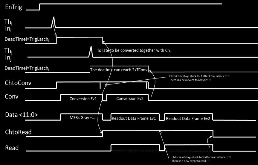
30 HITS ON 2 CHANNELS, 2 CONVERSIONS PAGE 30

31 HITS ON 2 CHANNELS, SIMULTANEOUS CONVERSIONS FROM SAMPIC to FPGA TO FPGA from SAMPIC PAGE 31
32 CALIBRATION PHILOSOPHY SCAs-based chips are suffering from reproducible non-idealities which can be easily corrected after calibration: The goal is to find the set with the best performance/complexity ratio. But also to find the right set for the highest level of performance. SAMPIC actually offers very good performance with a reduced set of calibrations : Amplitude: cell pedestal and gain (linear or parabolic fit) Time: INL (one offset per cell) This leads to a limited volume of standard calibration data (6 Bytes/cell/sampling frequency = > 8 kbytes/chip/sampling frequency) => can easily be stored in the on-board EEPROM. These simple corrections could even be applied in the FPGA. Highest level calibrations permit debugging the chip and pushing the performance to its limit (still unknown). PAGE 32
33 SAMPIC0: XTALK MEASUREMENT 800mV, 1ns FWHM, 300ps risetime and falltime injected on channel 7(blue) Signal measured on the other channels Xtalk = derivative and decrease as the distance to the injection channel Xtalk is < +/-1% = (2%pp) Xtalk signal is bipolar with ~ equal positive and negative lobe Similar plot, but shifted if injection in another channel (red)


34 TIMING NON-LINEARITIES Dispersion of single delays => time DNL Cumulative effect => time INL. Gets worse with delay line length. Systematic & fixed effect => non equidistant samples => Time Base Distortion If we can measure it => we can correct it! But calibration and even more correction have to remain reasonable. Real signal Δt[cell] Fake signal After interpolation Remark: same type of problem occurs with interleaved ADCs

![Search of zero-crossing segments of a free running asynchronous sine wave => length[position] Calculate the average amplitude for zero-crossing segment for each cell.](/docs-images/88/117707597/images/35-2.jpg "Renormalize (divide by average amplitude for all the cells and multiply by the clock period/number of DLL steps) => time duration for each step = time DNL Integrate this plot: Fixed Pattern Jitter =")
35 TIME INL CALIBRATION AND CORRECTION 13ps rms 7.5ps rms Method we introduced in 2009 and used since for our analog memories, assuming that a sinewave is nearly linear in its zero crossing region: much more precise than statistical distribution Search of zero-crossing segments of a free running asynchronous sine wave => length[position] Calculate the average amplitude for zero-crossing segment for each cell. Renormalize (divide by average amplitude for all the cells and multiply by the clock period/number of DLL steps) => time duration for each step = time DNL Integrate this plot: Fixed Pattern Jitter = correction to apply to the time of each sample = time INL Time INL correction: Simple addition on T sample Also permits the calculation of real equidistant samples by interpolation or digital filtering.
Picosecond time measurement using ultra fast analog memories.
 Picosecond time measurement using ultra fast analog memories. Dominique Breton a, Eric Delagnes b, Jihane Maalmi a acnrs/in2p3/lal-orsay, bcea/dsm/irfu breton@lal.in2p3.fr Abstract The currently existing
A 4 Channel Waveform Sampling ASIC in 130 nm CMOS
 A 4 Channel Waveform Sampling ASIC in 130 nm CMOS E. Oberla, H. Grabas, J.F. Genat, H. Frisch Enrico Fermi Institute, University of Chicago K. Nishimura, G. Varner University of Hawai I Large Area Picosecond
A 4-Channel Fast Waveform Sampling ASIC in 130 nm CMOS
 A 4-Channel Fast Waveform Sampling ASIC in 130 nm CMOS E. Oberla, H. Grabas, M. Bogdan, J.F. Genat, H. Frisch Enrico Fermi Institute, University of Chicago K. Nishimura, G. Varner University of Hawai I
Development of a sampling ASIC for fast detector signals
 Development of a sampling ASIC for fast detector signals Hervé Grabas Work done in collaboration with Henry Frisch, Jean-François Genat, Eric Oberla, Gary Varner, Eric Delagnes, Dominique Breton. Signal
PARISROC, a Photomultiplier Array Integrated Read Out Chip
 PARISROC, a Photomultiplier Array Integrated Read Out Chip S. Conforti Di Lorenzo a, J.E. Campagne b, F. Dulucq a, C. de La Taille a, G. Martin-Chassard a, M. El Berni a, W. Wei c a OMEGA/LAL/IN2P3, centre
A Fast Waveform-Digitizing ASICbased DAQ for a Position & Time Sensing Large-Area Photo-Detector System
 A Fast Waveform-Digitizing ASICbased DAQ for a Position & Time Sensing Large-Area Photo-Detector System Eric Oberla on behalf of the LAPPD collaboration PHOTODET 2012 12-June-2012 Outline LAPPD overview:
SAMPIC: a readout chip for fast timing detectors in particle physics and medical imaging
 Journal of Physics: Conference Series PAPER OPEN ACCESS SAMPIC: a readout chip for fast timing detectors in particle physics and medical imaging To cite this article: Christophe Royon 2015 J. Phys.: Conf.
CATIROC a multichannel front-end ASIC to read out the SPMT system of the JUNO experiment
 CATIROC a multichannel front-end ASIC to read out the SPMT system of the JUNO experiment Dr. Selma Conforti (OMEGA/IN2P3/CNRS) OMEGA microelectronics group Ecole Polytechnique & CNRS IN2P3 http://omega.in2p3.fr
SAM (Swift Analogue Memory): a new GHz sampling ASIC for the HESS-II Front-End Electronics.
: a new GHz sampling ASIC for the HESS-II Front-End Electronics.") SAM (Swift Analogue Memory): a new GHz sampling ASIC for the HESS-II Front-End Electronics. E. Delagnes 1, Y. Degerli 1, P. Goret 1, P. Nayman 2, F. Toussenel 2, P. Vincent 2 1 DAPNIA, CEA/Saclay 2 IN2P3/LPNHE
SAM (Swift Analogue Memory): a new GHz sampling ASIC for the HESS-II Front-End Electronics. E. Delagnes 1, Y. Degerli 1, P. Goret 1, P. Nayman 2, F. Toussenel 2, P. Vincent 2 1 DAPNIA, CEA/Saclay 2 IN2P3/LPNHE
WaveCatcher Family User s Manual
 WaveCatcher Family User s Manual Date: 1/6/2017 WaveCatcher Family User s Manual By D.Breton & J.Maalmi, LAL Orsay V/Ref. : 1.2 WaveCatcher Family User s Manual - 2 - PURPOSE OF THIS MANUAL This User s
A Low Power Multi-Channel Single Ramp ADC With up to 3.2 GHz Virtual Clock
 1 A Low Power Multi-Channel Single Ramp ADC With up to 3.2 GHz Virtual Clock Eric Delagnes, Dominique Breton, Francis Lugiez, and Reza Rahmanifard Abstract During the last decade, ADCs using single ramp
Analogue to Digital Conversion
 Analogue to Digital Conversion Turns electrical input (voltage/current) into numeric value Parameters and requirements Resolution the granularity of the digital values Integral NonLinearity proportionality
Implementation of High Precision Time to Digital Converters in FPGA Devices
 Implementation of High Precision Time to Digital Converters in FPGA Devices Tobias Harion () Implementation of HPTDCs in FPGAs January 22, 2010 1 / 27 Contents: 1 Methods for time interval measurements
Development of a 20 GS/s Sampling Chip in 130nm CMOS Technology
 Development of a 20 GS/s Sampling Chip in 130nm CMOS Technology 2009 IEEE Nuclear Science Symposium, Orlando, Florida, October 28 th 2009 Jean-Francois Genat On behalf of Mircea Bogdan 1, Henry J. Frisch
Analogue to Digital Conversion
 Analogue to Digital Conversion Turns electrical input (voltage/current) into numeric value Parameters and requirements Resolution the granularity of the digital values Integral NonLinearity proportionality
A 130nm CMOS Evaluation Digitizer Chip for Silicon Strips readout at the ILC
 A 130nm CMOS Evaluation Digitizer Chip for Silicon Strips readout at the ILC Jean-Francois Genat Thanh Hung Pham on behalf of W. Da Silva 1, J. David 1, M. Dhellot 1, D. Fougeron 2, R. Hermel 2, J-F. Huppert
How different FPGA firmware options enable digitizer platforms to address and facilitate multiple applications
 How different FPGA firmware options enable digitizer platforms to address and facilitate multiple applications 1 st of April 2019 Marc.Stackler@Teledyne.com March 19 1 Digitizer definition and application
A Low Power Multi-Channel Single Ramp ADC With Up to 3.2 GHz Virtual Clock
 A Low Power Multi-Channel Single Ramp ADC With Up to 3.2 GHz Virtual Clock E. Delagnes, D. Breton, F. Lugiez, R. Rahmanifard To cite this version: E. Delagnes, D. Breton, F. Lugiez, R. Rahmanifard. A Low
A 4 GSample/s 8-bit ADC in. Ken Poulton, Robert Neff, Art Muto, Wei Liu, Andrew Burstein*, Mehrdad Heshami* Agilent Laboratories Palo Alto, California
 A 4 GSample/s 8-bit ADC in 0.35 µm CMOS Ken Poulton, Robert Neff, Art Muto, Wei Liu, Andrew Burstein*, Mehrdad Heshami* Agilent Laboratories Palo Alto, California 1 Outline Background Chip Architecture
ADC Measurements PARISROC Chip. Selma Conforti Di Lorenzo OMEGA/LAL Orsay
 ADC Measurements PARISROC Chip Selma Conforti Di Lorenzo OMEGA/LAL Orsay PARISROC ADC Measurements Ecole Microélectronique_11/16 octobre 2009 conforti@lal.in2p3.fr 2 TEST BOARD TEST BENCH ASIC FPGA USB
Analog Peak Detector and Derandomizer
 Analog Peak Detector and Derandomizer G. De Geronimo, A. Kandasamy, P. O Connor Brookhaven National Laboratory IEEE Nuclear Sciences Symposium, San Diego November 7, 2001 Multichannel Readout Alternatives
Study of the ALICE Time of Flight Readout System - AFRO
 Study of the ALICE Time of Flight Readout System - AFRO Abstract The ALICE Time of Flight Detector system comprises about 176.000 channels and covers an area of more than 100 m 2. The timing resolution
MODEL AND MODEL PULSE/PATTERN GENERATORS
 AS TEE MODEL 12010 AND MODEL 12020 PULSE/PATTERN GENERATORS Features: 1.6GHz or 800MHz Models Full Pulse and Pattern Generator Capabilities Programmable Patterns o User Defined o 16Mbit per channel o PRBS
PARISROC, a Photomultiplier Array Integrated Read Out Chip.
 PARISROC, a Photomultiplier Array Integrated Read Out Chip. S. Conforti Di Lorenzo*, J.E.Campagne, F. Dulucq*, C. de La Taille*, G. Martin-Chassard*, M. El Berni. LAL/IN2P3, Laboratoire de l Accélérateur
nanomca 80 MHz HIGH PERFORMANCE, LOW POWER DIGITAL MCA Model Numbers: NM0530 and NM0530Z
 datasheet nanomca 80 MHz HIGH PERFORMANCE, LOW POWER DIGITAL MCA Model Numbers: NM0530 and NM0530Z I. FEATURES Finger-sized, high performance digital MCA. 16k channels utilizing smart spectrum-size technology
A PC-BASED TIME INTERVAL COUNTER WITH 200 PS RESOLUTION
 A PC-BASED TIME INTERVAL COUNTER WITH 200 PS RESOLUTION Józef Kalisz and Ryszard Szplet Military University of Technology Kaliskiego 2, 00-908 Warsaw, Poland Tel: +48 22 6839016; Fax: +48 22 6839038 E-mail:
MAROC: Multi-Anode ReadOut Chip for MaPMTs
 Author manuscript, published in "2006 IEEE Nuclear Science Symposium, Medical Imaging Conference, and 15th International Room 2006 IEEE Nuclear Science Symposium Conference Temperature Record Semiconductor
MuLan Experiment Progress Report
 BV 37 PSI February 16 2006 p. 1 MuLan Experiment Progress Report PSI Experiment R 99-07 Françoise Mulhauser, University of Illinois at Urbana Champaign (USA) The MuLan Collaboration: BERKELEY BOSTON ILLINOIS
Traditional analog QDC chain and Digital Pulse Processing [1]
![Traditional analog QDC chain and Digital Pulse Processing [1]](/thumbs/75/72878980.jpg "Traditional analog QDC chain and Digital Pulse Processing [1]") Giuliano Mini Viareggio April 22, 2010 Introduction The aim of this paper is to compare the energy resolution of two gamma ray spectroscopy setups based on two different acquisition chains; the first chain
Giuliano Mini Viareggio April 22, 2010 Introduction The aim of this paper is to compare the energy resolution of two gamma ray spectroscopy setups based on two different acquisition chains; the first chain
Status of SVT front-end electronics M. Citterio on behalf of INFN and University of Milan
 XVII SuperB Workshop and Kick Off Meeting: ETD3 Parallel Session Status of SVT front-end electronics M. Citterio on behalf of INFN and University of Milan Index SVT: system status Parameter space Latest
Towards an ADC for the Liquid Argon Electronics Upgrade
 1 Towards an ADC for the Liquid Argon Electronics Upgrade Gustaaf Brooijmans Upgrade Workshop, November 10, 2009 2 Current LAr FEB Existing FEB (radiation tolerant for LHC, but slhc?) Limits L1 latency
ANITA ROSS Trigger/Digitizer/DAQ. Gary S. Varner University of Hawai, i, Manoa ANITA Collaboration JPL March 2004
 ANITA ROSS Trigger/Digitizer/DAQ Gary S. Varner University of Hawai, i, Manoa ANITA Collaboration Meeting @ JPL March 2004 Overview System overview Reiterate, with ROSS simplifications ROSS trigger descope
MSO Supplied with a full SDK including example programs Software compatible with Windows XP, Windows Vista and Windows 7 Free Technical Support
 PicoScope 2205 MSO USB-POWERED MIXED SIGNAL OSCILLOSCOPE Think logically... 25 MHz analog bandwidth 100 MHz max. digital input frequency 200 MS/s mixed signal sampling Advanced digital triggers SDK and
Electronic Readout System for Belle II Imaging Time of Propagation Detector
 Electronic Readout System for Belle II Imaging Time of Propagation Detector Dmitri Kotchetkov University of Hawaii at Manoa for Belle II itop Detector Group March 3, 2017 Barrel Particle Identification
Arbitrary/Function Waveform Generators 4075B Series
 Data Sheet Arbitrary/Function Waveform Generators Point-by-Point Signal Integrity The Arbitrary/Function Waveform Generators are versatile high-performance single- and dual-channel arbitrary waveform generators
Multi-Channel Charge Pulse Amplification, Digitization and Processing ASIC for Detector Applications
 1.0 Multi-Channel Charge Pulse Amplification, Digitization and Processing ASIC for Detector Applications Peter Fischer for Tim Armbruster, Michael Krieger and Ivan Peric Heidelberg University Motivation
CLARO A fast Front-End ASIC for Photomultipliers
 An introduction to CLARO A fast Front-End ASIC for Photomultipliers INFN Milano-Bicocca Paolo Carniti Andrea Giachero Claudio Gotti Matteo Maino Gianluigi Pessina 2 nd SuperB Collaboration Meeting Dec
Transmission-Line Readout with Good Time and Space Resolution for Large-Area MCP-PMTs
 Transmission-Line Readout with Good Time and Space Resolution for Large-Area MCP-PMTs Fukun Tang (UChicago) C. Ertley, H. Frisch, J-F. Genat, Tyler Natoli (UChicago) J. Anderson, K. Byrum, G. Drake, E.
Data Acquisition System for the Angra Project
 Angra Neutrino Project AngraNote 012-2009 (Draft) Data Acquisition System for the Angra Project H. P. Lima Jr, A. F. Barbosa, R. G. Gama Centro Brasileiro de Pesquisas Físicas - CBPF L. F. G. Gonzalez
High resolution photon timing with MCP-PMTs: a comparison of
 High resolution photon timing with MCP-PMTs: a comparison of commercial constant fraction discriminator (CFD) with ASIC-based waveform digitizers TARGET and WaveCatcher. D. Breton *, E. Delagnes **, J.
New Features of IEEE Std Digitizing Waveform Recorders
 New Features of IEEE Std 1057-2007 Digitizing Waveform Recorders William B. Boyer 1, Thomas E. Linnenbrink 2, Jerome Blair 3, 1 Chair, Subcommittee on Digital Waveform Recorders Sandia National Laboratories
ArbStudio Arbitrary Waveform Generators
 ArbStudio Arbitrary Waveform Generators Key Features Outstanding performance with 16-bit, 1 GS/s sample rate and 2 Mpts/Ch 2 and 4 channel models Digital pattern generator PWM mode Sweep and burst modes
PoS(PhotoDet 2012)030
030") NECTAR: New Electronics for the Cherenkov Telescope Array a, J. Bolmont a, P. Corona a, E. Delagnes b, D. Dzahini c, F. Feinstein d, D. Gascon e, J.-F. Glicenstein b, P. Nayman a, F. Rarbi c, M. Ribó e,
NECTAR: New Electronics for the Cherenkov Telescope Array a, J. Bolmont a, P. Corona a, E. Delagnes b, D. Dzahini c, F. Feinstein d, D. Gascon e, J.-F. Glicenstein b, P. Nayman a, F. Rarbi c, M. Ribó e,
Motivation Overview Grounding & Shielding L1 Trigger System Diagrams Front-End Electronics Modules
 F.J. Barbosa, Jlab 1. 2. 3. 4. 5. 6. 7. 8. 9. Motivation Overview Grounding & Shielding L1 Trigger System Diagrams Front-End Electronics Modules Safety Summary 1 1. Motivation Hall D will begin operations
9200 Series, 300 MHz Programmable Pulse Generator
 9200 Series, 300 MHz Programmable Pulse Generator Main Features Variable edge pulses (1 nsec to 1 msec) at rates to 250 MHz Fast 300 psec edges to 300 MHz Wide output swings to 32 V at pulse rates to 50
arxiv: v2 [physics.ins-det] 11 Aug 2016
![arxiv: v2 [physics.ins-det] 11 Aug 2016](/thumbs/83/87428448.jpg "arxiv: v2 [physics.ins-det] 11 Aug 2016") Measurements of timing resolution of ultra-fast silicon detectors with the SAMPIC waveform digitizer arxiv:1604.02385v2 [physics.ins-det] 11 Aug 2016 D. Breton a, V. De Cacqueray b,1, E. Delagnes b, H.
Measurements of timing resolution of ultra-fast silicon detectors with the SAMPIC waveform digitizer arxiv:1604.02385v2 [physics.ins-det] 11 Aug 2016 D. Breton a, V. De Cacqueray b,1, E. Delagnes b, H.
ArbStudio Arbitrary Waveform Generators. Powerful, Versatile Waveform Creation
 ArbStudio Arbitrary Waveform Generators Powerful, Versatile Waveform Creation UNMATCHED WAVEFORM UNMATCHED WAVEFORM GENERATION GENERATION Key Features 125 MHz bandwidth 1 GS/s maximum sample rate Long
Cost-Effective Traceability for Oscilloscope Calibration. Author: Peter B. Crisp Head of Metrology Fluke Precision Instruments, Norwich, UK
 Cost-Effective Traceability for Oscilloscope Calibration Author: Peter B. Crisp Head of Metrology Fluke Precision Instruments, Norwich, UK Abstract The widespread adoption of ISO 9000 has brought an increased
Progress towards a 256 channel multianode microchannel plate photomultiplier system with picosecond timing
 Progress towards a 256 channel multianode microchannel plate photomultiplier system with picosecond timing J S Lapington 1, T Conneely 1,3, T J R Ashton 1, P Jarron 2, M Despeisse 2, and F Powolny 2 1
10.1: A 4 GSample/s 8b ADC in 0.35-um CMOS
 10.1: A 4 GSample/s 8b ADC in 0.35-um CMOS Ken Poulton, Robert Neff, Art Muto, Wei Liu*, Andy Burstein**, Mehrdad Heshami*** Agilent Technologies, Palo Alto, CA *Agilent Technologies, Colorado Springs,
DG5000 Series Specifications
 DG5000 Series Specifications All the specifications can be guaranteed if the following two conditions are met unless where noted. The generator is within the calibration period and has performed self-calibration.
Multiple Reference Clock Generator
 A White Paper Presented by IPextreme Multiple Reference Clock Generator Digitial IP for Clock Synthesis August 2007 IPextreme, Inc. This paper explains the concept behind the Multiple Reference Clock Generator
ARTICLE IN PRESS. Nuclear Instruments and Methods in Physics Research A
 Nuclear Instruments and Methods in Physics Research A 614 (2010) 308 312 Contents lists available at ScienceDirect Nuclear Instruments and Methods in Physics Research A journal homepage: www.elsevier.com/locate/nima
A 0.2-to-1.45GHz Subsampling Fractional-N All-Digital MDLL with Zero-Offset Aperture PD-Based Spur Cancellation and In-Situ Timing Mismatch Detection
 A 0.2-to-1.45GHz Subsampling Fractional-N All-Digital MDLL with Zero-Offset Aperture PD-Based Spur Cancellation and In-Situ Timing Mismatch Detection Somnath Kundu 1, Bongjin Kim 1,2, Chris H. Kim 1 1
Programmable Pulse/Pattern Generator PSPL1P601 and PSPL1P602 Datasheet
 Programmable Pulse/Pattern Generator PSPL1P601 and PSPL1P602 Datasheet Applications Serial data generation Jitter tolerance testing General purpose pulse generator The PSPL1P601 and PSPL1P602 are effectively
Electron-Bombarded CMOS
 New Megapixel Single Photon Position Sensitive HPD: Electron-Bombarded CMOS University of Lyon / CNRS-IN2P3 in collaboration with J. Baudot, E. Chabanat, P. Depasse, W. Dulinski, N. Estre, M. Winter N56:
SAMPULSE50GHz and SAMPULSE70GHzANT PULSER/SAMPLER DEMO BOARD
 SAMPULSE50GHz and SAMPULSE70GHzANT PULSER/SAMPLER DEMO BOARD REV B. PRELIMINARY USER MANUAL 2/25/15 Figure 1. Connections to SAMPULSE50GHz (left) or SAMPULSE70GHzANT (right). INTRODUCTION: The SAMPULSE50GHz
RIGOL Data Sheet. DG3000 Series Function/Arbitrary Waveform Generator DG3121A, DG3101A, DG3061A. Product Overview. Easy to Use Design.
 RIGOL Data Sheet DG3000 Series Function/Arbitrary Waveform Generator DG3121A, DG3101A, DG3061A Product Overview DG3000 Series Function/Arbitrary Waveform Generators adopt DDS technology, which enables
Calorimeter Monitoring at DØ
 Calorimeter Monitoring at DØ Calorimeter Monitoring at DØ Robert Kehoe ATLAS Calibration Mtg. December 1, 2004 Southern Methodist University Department of Physics Detector and Electronics Monitoring Levels
Octal ASD Certification Tests at Michigan
 Octal ASD Certification Tests at Michigan J. Chapman, Tiesheng Dai, & Tuan Bui August 30, 2002 - CERN Goals of Michigan Test Confirm actual deadtime vrs setting. Hits/event vrs trigger rate (I/O traffic
Chromatic X-Ray imaging with a fine pitch CdTe sensor coupled to a large area photon counting pixel ASIC
 Chromatic X-Ray imaging with a fine pitch CdTe sensor coupled to a large area photon counting pixel ASIC R. Bellazzini a,b, G. Spandre a*, A. Brez a, M. Minuti a, M. Pinchera a and P. Mozzo b a INFN Pisa
AWG-GS bit 2.5GS/s Arbitrary Waveform Generator
 KEY FEATURES 2.5 GS/s Real Time Sample Rate 14-bit resolution 2 Channels Long Memory: 64 MS/Channel Direct DAC Out - DC Coupled: 1.6 Vpp Differential / 0.8 Vpp > 1GHz Bandwidth RF Amp Out AC coupled -10
Requirements and Specifications of the TDC for the ATLAS Precision Muon Tracker
 ATLAS Internal Note MUON-NO-179 14 May 1997 Requirements and Specifications of the TDC for the ATLAS Precision Muon Tracker Yasuo Arai KEK, National High Energy Accelerator Research Organization Institute
nanomca datasheet I. FEATURES
 datasheet nanomca I. FEATURES Finger-sized, high performance digital MCA. 16k channels utilizing smart spectrum-size technology -- all spectra are recorded and stored as 16k spectra with instant, distortion-free
ISSCC 2003 / SESSION 4 / CLOCK RECOVERY AND BACKPLANE TRANSCEIVERS / PAPER 4.3
 ISSCC 2003 / SESSION 4 / CLOCK RECOVERY AND BACKPLANE TRANSCEIVERS / PAPER 4.3 4.3 A Second-Order Semi-Digital Clock Recovery Circuit Based on Injection Locking M.-J. Edward Lee 1, William J. Dally 1,2,
NIM INDEX. Attenuators. ADCs (Peak Sensing) Discriminators. Translators Analog Pulse Processors Amplifiers (Fast) Amplifiers (Spectroscopy)
 Discriminators. Translators Analog Pulse Processors Amplifiers (Fast) Amplifiers (Spectroscopy)") NIM The NIM-Nuclear Instrumentation Module standard is a very popular form factor widely used in experimental Particle and Nuclear Physics setups. Defined the first time by the U.S. Atomic Energy Commission
NIM The NIM-Nuclear Instrumentation Module standard is a very popular form factor widely used in experimental Particle and Nuclear Physics setups. Defined the first time by the U.S. Atomic Energy Commission
The High-Voltage Monolithic Active Pixel Sensor for the Mu3e Experiment
 The High-Voltage Monolithic Active Pixel Sensor for the Mu3e Experiment Shruti Shrestha On Behalf of the Mu3e Collaboration International Conference on Technology and Instrumentation in Particle Physics
Another way to implement a folding ADC
 Another way to implement a folding ADC J. Van Valburg and R. van de Plassche, An 8-b 650 MHz Folding ADC, IEEE JSSC, vol 27, #12, pp. 1662-6, Dec 1992 Coupled Differential Pair J. Van Valburg and R. van
Multiple Instrument Station Module
 Multiple Instrument Station Module Digital Storage Oscilloscope Vertical Channels Sampling rate Bandwidth Coupling Input impedance Vertical sensitivity Vertical resolution Max. input voltage Horizontal
Lecture 160 Examples of CDR Circuits in CMOS (09/04/03) Page 160-1
 Page 160-1") Lecture 160 Examples of CDR Circuits in CMOS (09/04/03) Page 160-1 LECTURE 160 CDR EXAMPLES INTRODUCTION Objective The objective of this presentation is: 1.) Show two examples of clock and data recovery
Lecture 160 Examples of CDR Circuits in CMOS (09/04/03) Page 160-1 LECTURE 160 CDR EXAMPLES INTRODUCTION Objective The objective of this presentation is: 1.) Show two examples of clock and data recovery
EMX-1434 APPLICATIONS FEATURES A SMART PXI EXPRESS 4-CHANNEL KSA/S ARBITRARY WAVEFORM GENERATOR
 83-0061-000 15A D A T A S H E E T EMX-1434 SMART PXI EXPRESS 4-CHANNEL 204.8 KSA/S ARBITRARY WAVEFORM GENERATOR APPLICATIONS Modal / GVT (Ground Vehicle Testing) Acoustics Shock / Vibration Rotational
Development of Radiation-Hard ASICs for the ATLAS Phase-1 Liquid Argon Calorimeter Readout Electronics Upgrade
 Development of Radiation-Hard ASICs for the ATLAS Phase-1 Liquid Argon Calorimeter Readout Electronics Upgrade Tim Andeen*, Jaroslav BAN, Nancy BISHOP, Gustaaf BROOIJMANS, Alex EMERMAN,Ines OCHOA, John
A single-slope 80MS/s ADC using two-step time-to-digital conversion
 A single-slope 80MS/s ADC using two-step time-to-digital conversion The MIT Faculty has made this article openly available. Please share how this access benefits you. Your story matters. Citation As Published
Jean-Francois Genat. Fast Timing Workshop Lyon, Oct 15 th 2008
 Picosecond Timing with Micro-Channel coc Plate Detectors Jean-Francois Genat Fast Timing Workshop Lyon, Oct 15 th 2008 Fast Timing Devices Multi-anodes PMTs Si-PMTs MCPs Dynodes Quenched Geiger Micro-Pores
Model MHz Arbitrary Waveform Generator Specifications
 50MHz Arbitrary Waveform Generator s DISPLAY: Graph mode for visual verification of signal settings. CAPABILITY: Standard waveforms: Sine, Square, Ramp, Triangle, Pulse, Noise, DC Built-in arbitrary waveforms:
Digital Waveform Recorders
 Digital Waveform Recorders Error Models & Performance Measures Dan Knierim, Tektronix Fellow Experimental Set-up for high-speed phenomena Transducer(s) high-speed physical phenomenon under study physical
Buffered LABRADOR (BLAB3) Design Review. Gary S. Varner 4 NOV 09
 Design Review. Gary S. Varner 4 NOV 09") Buffered LABRADOR (BLAB3) Design Review Gary S. Varner 4 NOV 09 Baseline confirmation Goals for today Ice Radio Sampler (IRS) as sampling/storage array basis High rate/long latency architecture Review
Buffered LABRADOR (BLAB3) Design Review Gary S. Varner 4 NOV 09 Baseline confirmation Goals for today Ice Radio Sampler (IRS) as sampling/storage array basis High rate/long latency architecture Review
KLauS4: A Multi-Channel SiPM Charge Readout ASIC in 0.18 µm UMC CMOS Technology
 1 KLauS: A Multi-Channel SiPM Charge Readout ASIC in 0.18 µm UMC CMOS Technology Z. Yuan, K. Briggl, H. Chen, Y. Munwes, W. Shen, V. Stankova, and H.-C. Schultz-Coulon Kirchhoff Institut für Physik, Heidelberg
Ice Radio Sampler (IRS) & Buffered LABRADOR #3 (BLAB3) Preliminary Specification Review. Gary S. Varner Internal ID Lab Review, 10 AUG 09
 & Buffered LABRADOR #3 (BLAB3) Preliminary Specification Review. Gary S. Varner Internal ID Lab Review, 10 AUG 09") Ice Radio Sampler (IRS) & Buffered LABRADOR #3 (BLAB3) Preliminary Specification Review Gary S. Varner Internal ID Lab Review, 10 AUG 09 Goals for both ASICs Confirm Design Specifications Table Listing
Ice Radio Sampler (IRS) & Buffered LABRADOR #3 (BLAB3) Preliminary Specification Review Gary S. Varner Internal ID Lab Review, 10 AUG 09 Goals for both ASICs Confirm Design Specifications Table Listing
Model 745 Series. Berkeley Nucleonics Test, Measurement and Nuclear Instrumentation since Model 845-HP Datasheet BNC
 Model 845-HP Datasheet Model 745 Series Portable 20+ GHz Microwave Signal Generator High Power +23dBM Power Output 250 fs Digital Delay Generator BNC Berkeley Nucleonics Test, Measurement and Nuclear Instrumentation
The Trigger System of the MEG Experiment
 The Trigger System of the MEG Experiment On behalf of D. Nicolò F. Morsani S. Galeotti M. Grassi Marco Grassi INFN - Pisa Lecce - 23 Sep. 2003 1 COBRA magnet Background Rate Evaluation Drift Chambers Target
HIGH-RESOLUTION time interval measurement circuits
 1360 IEEE JOURNAL OF SOLID-STATE CIRCUITS, VOL. 34, NO. 10, OCTOBER 1999 A High-Resolution Time Interpolator Based on a Delay Locked Loop and an RC Delay Line Manuel Mota, Member, IEEE, and Jorgen Christiansen,
Application Note AN-23 Copyright September, 2009
 Removing Jitter From Picosecond Pulse Measurements James R. Andrews, Ph.D, IEEE Fellow PSPL Founder and former President (retired) INTRODUCTION: Uncertainty is always present in every measurement. Uncertainties
Fundamentals of Data Converters. DAVID KRESS Director of Technical Marketing
 Fundamentals of Data Converters DAVID KRESS Director of Technical Marketing 9/14/2016 Analog to Electronic Signal Processing Sensor (INPUT) Amp Converter Digital Processor Actuator (OUTPUT) Amp Converter
Keysight Technologies E8257D PSG Microwave Analog Signal Generator. Data Sheet
 Keysight Technologies E8257D PSG Microwave Analog Signal Generator Data Sheet 02 Keysight E8257D Microwave Analog Signal Generator - Data Sheet Table of Contents Specifications... 4 Frequency... 4 Step
MSO Supplied with a full SDK including example programs Software compatible with Windows XP, Windows Vista and Windows 7 Free Technical Support
 PicoScope 2205 MSO USB-POWERED MIXED SIGNAL OSCILLOSCOPE Think logically... 25 MHz analog bandwidth 100 MHz max. digital input frequency 200 MS/s mixed signal sampling Advanced digital triggers SDK and
Model 310H Fast 800V Pulse Generator
 KEY FEATURES Temperature Stability +/-5ppm 100 V to 800 V into 50 Ω
TAPR TICC Timestamping Counter Operation Manual. Introduction
 TAPR TICC Timestamping Counter Operation Manual Revised: 23 November 2016 2016 Tucson Amateur Packet Radio Corporation Introduction The TAPR TICC is a two-channel timestamping counter ("TSC") implemented
Agilent 8657A/8657B Signal Generators
 Agilent / Signal Generators Profile Spectral performance for general-purpose test Overview The Agilent Technologies and signal generators are designed to test AM, FM, and pulsed receivers as well as components.
MAROC: Multi-Anode ReadOut Chip for MaPMTs
 MAROC: Multi-Anode ReadOut Chip for MaPMTs P. Barrillon, S. Blin, M. Bouchel, T. Caceres, C. De La Taille, G. Martin, P. Puzo, N. Seguin-Moreau To cite this version: P. Barrillon, S. Blin, M. Bouchel,
AGATA preamplifiers: issues and status
 AGATA preamplifiers: issues and status Preamplifier group AGATA week Legnaro (Padova), Italy 15-19 September 2003 Speaker: Alberto Pullia, 16 September 2003 Work forces main developments Discrete hybrid
G5100A: 50 MHz Arbitrary Function Generator
 G5100A: 50 MHz Arbitrary Function Generator Key Features 50 MHz Sine Wave 25 MHz Square Wave Pulse, Ramp, Triangle, Noise, and DC waveforms AM, FM, PM, FSK, and PWM modulation types Linear & logarithmic
Chapter 13 Specifications
 RIGOL All the specifications can be guaranteed if the following two conditions are met unless where noted. The generator is within the calibration period and has performed self-calibration. The generator
nanomca-sp datasheet I. FEATURES
 datasheet nanomca-sp 80 MHz HIGH PERFORMANCE, LOW POWER DIGITAL MCA WITH BUILT IN PREAMPLIFIER Model Numbers: SP0534A/B to SP0539A/B Standard Models: SP0536B and SP0536A I. FEATURES Built-in preamplifier
nanodpp datasheet I. FEATURES
 datasheet nanodpp I. FEATURES Ultra small size high-performance Digital Pulse Processor (DPP). 16k channels utilizing smart spectrum-size technology -- all spectra are recorded and stored as 16k spectra
ADC and DAC Standards Update
 ADC and DAC Standards Update Revised ADC Standard 2010 New terminology to conform to Std-1057 SNHR became SNR SNR became SINAD Added more detailed test-setup descriptions Added more appendices Reorganized
DG4000 Series Waveform Generators
 No.1 DG4000 DG4000 series is a multifunctional generator that combines many functions in one, including Function Generator, Arbitrary Waveform Generator, Pulse Generator, Harmonic Generator, Analog/Digital
GRETINA. Electronics. Auxiliary Detector Workshop. Sergio Zimmermann LBNL. Auxiliary Detectors Workshop. January 28, 2006
 GRETINA Auxiliary Detector Workshop Electronics Sergio Zimmermann LBNL 1 Outline Electronic Interface Options Digitizers Trigger/Timing System Grounding and Shielding Summary 2 Interface Options Three
Analog to Digital Conversion
 Analog to Digital Conversion Florian Erdinger Lehrstuhl für Schaltungstechnik und Simulation Technische Informatik der Uni Heidelberg VLSI Design - Mixed Mode Simulation F. Erdinger, ZITI, Uni Heidelberg
Time Matters How Power Meters Measure Fast Signals
 Time Matters How Power Meters Measure Fast Signals By Wolfgang Damm, Product Management Director, Wireless Telecom Group Power Measurements Modern wireless and cable transmission technologies, as well