TABLE OF CONTENTS 1 GENERAL INFORMATION Identification of the Testing Laboratory... 3
|
|
|
- Susan Bruce
- 5 years ago
- Views:
Transcription
1
2 1 Report No.: BL-SZ Revision History Version Issue Date Revision Content Rev. 01 Oct. 25, 2016 Initial Issue Rev. 02 Rev. 03 Rev. 04 Mar. 08, 2017 Mar. 17, 2017 Mar. 23, 2017 Evaluation of TNV circuits Evaluation of TNV circuits and update the report Update the report TABLE OF CONTENTS 1 GENERAL INFORMATION Identification of the Testing Laboratory Identification of the Responsible Testing Location Announce RODUCT INFORMATION Applicant Manufacturer Factory General Description for Equipment under Test (EUT) Technical Information Ancillary Equipment SUMMARY OF TEST Test Standards ossible test case verdict Test item General information GENERAL TEST CONFIGURATIONS Test Environments Test Equipment List Test Condition TEST RESULTS roduct Marking Label HOTO DOCUMEN / 56
3 1 Report No.: BL-SZ GENERAL INFORMATION 1.1 Identification of the Testing Laboratory Company Name Shenzhen BALUN Technology Co., Ltd. Address Block B, 1st FL, Baisha Science and Technology ark, Shahe Xi Road, Nanshan District, Shenzhen, Guangdong rovince..r. China hone Number Fax Number Identification of the Responsible Testing Location Test Location 1 Address Accreditation Certificate Description Shenzhen BALUN Technology Co., Ltd. Block B, 1st FL, Baisha Science and Technology ark, Shahe Xi Road, Nanshan District, Shenzhen, Guangdong rovince..r. China The Laboratory has met the requirements of the CNAS Accreditation Criteria, has demonstrated compliance with ISO/IEC Standard 17025:2005. The accreditation certificate number is L6791. All measurement facilities used to collect the measurement data are located at Block B, FL 1, Baisha Science and Technology ark, Shahe Xi Road, Nanshan District, Shenzhen, Guangdong rovince,. R. China Announce (1) The test report is invalid if not marked with the signatures of the persons responsible for preparing and approving the test report. (2) The test report is invalid if there is any evidence and/or falsification. (3) The results documented in this report apply only to the tested sample, under the conditions and modes of operation as described herein. (4) This document may not be altered or revised in any way unless done so by BALUN and all revisions are duly noted in the revisions section. (5) Content of the test report, in part or in full, cannot be used for publicity and/or promotional purposes without prior written approval from the laboratory. 3 / 56
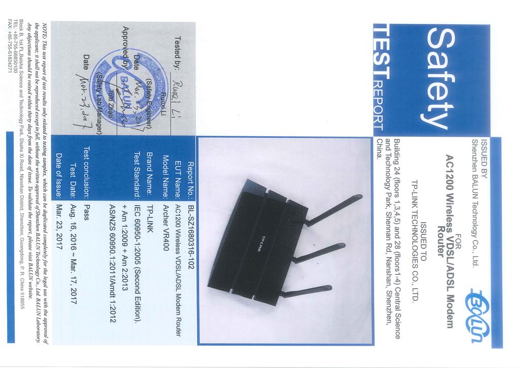
4 1 2 RODUCT INFORMATION Report No.: BL-SZ Applicant Applicant Address T-LINK TECHNOLOGIES CO., LTD. Building 24 (floors 1,3,4,5) and 28 (floors1-4) Central Science and Technology ark, Shennan Rd, Nanshan, Shenzhen, China. 2.2 Manufacturer Manufacturer Address T-LINK TECHNOLOGIES CO., LTD. Building 24 (floors 1,3,4,5) and 28 (floors1-4) Central Science and Technology ark, Shennan Rd, Nanshan, Shenzhen, China. 2.3 Factory Factory / Address / 2.4 General Description for Equipment under Test (EUT) EUT Name Model Name Brand Name Dimensions (Approx.) Weight (Approx.) AC1200 Wireless VDSL/ADSL Modem Router Archer VR400 T-LINK 230mm x 158mm x 32 mm 460g 2.5 Technical Information The requirement for the following technical information of the EUT was tested in this report: Ratings Input: DC 12V 1.5A Equipment mobility [X] movable [] hand-held [] transportable [] stationary [] for building-in [] direct plug-in Connection to the mains [] pluggable equipment [] type A [] type B [] permanent connection [] detachable power supply cord [] non-detachable power supply cord [X] not directly connected to the mains Over voltage category [ X ] OVC I [] OVC II [] OVC III [] OVC IV (OVC) [] other: Operating condition [ X ]Continuous; [ ] rated operating/ resting time Considered current rating of protective device as part of the 4 / 56
5 1 Report No.: BL-SZ building installation (A) Mains supply tolerance (%) or absolute mains supply values Tested for IT power [] Yes [X] No systems IT testing, phase-phase voltage (V) Class of equipment [] Class I [] Class II [X] Class III [] Not classified I protection class I20 ollution degree (D) [] D 1 [X] D 2 [] D 3 Altitude during Up to 2000m operation (m) Altitude of test Below 2000m laboratory (m) Maximum ambient 40 temperature Note: The above EUT information was declared by manufacturer and for more detailed features description, please refer to the manufacturer's specifications or user's manual. 2.6 Ancillary Equipment Ancillary Equipment I.T.E.OWER SULY Trand Name T-LINK Model No. T E1 Input AC V~ 50/60Hz 0.6A Output 12V 1.5A 5 / 56
6 1 3 SUMMARY OF TEST Report No.: BL-SZ Test Standards No. Identity Document Title IEC :2005 (Second Edition) + Am 1:2009 Information technology equipment Am 2:2013 Safety- art 1: General requirements Information technology equipment - 2 AS/NZS :2011/Amdt 1:2012 Safety- art 1: General requirements 3.2 ossible test case verdict ossible test case verdicts: -test case does not apply to the test object. : -test object does meet the requirement...: (ass) -test object does not meet the requirement..: F(Fail) 3.3 Test item Tests performed (name of test and test clause): 1.6 Input test 1.7 Marking testing 2.1 rotection from electric shock and energy hazards 2.2 SELV circuit 2.3 TNV circuits 2.4 Limited current circuit test 2.5 Limited power sources 2.9 Electrical insulation 2.10 Clearances, creepage distances and distances through insulation 4.2 Mechanical strength Batteries 4.5 Thermal requirements Resistance to abnormal heat 5.1 Touch current and protective conductor current 5.2 Electric strength 5.3 Abnormal operating and fault conditions Impulse test Steady-state test Summary of compliance with National Differences: List of countries addressed: 1. AUSTRALIAN / NEW ZEALAND DIFFERENCES 6 / 56
7 1 3.4 General information Report No.: BL-SZ General remarks: The test results presented in this report relate only to the object tested. This report shall not be reproduced, except in full, without the written approval of the Issuing testing laboratory. "(See Enclosure #)" refers to additional information appended to the report. "(See appended table)" refers to a table appended to the report. General information: -The equipment is an AC1200 Wireless VDSL/ADSL Modem Router, Supplied by 12VDC power supply. -Circuit characteristics: Only secondary (SELV) circuit and TNV-3 circuit. -Instructions and equipment marking related to safety is applied in the language that is acceptable in the country in which the equipment is to be sold. 7 / 56
8 1 4 GENERAL TEST CONFIGURATIONS Report No.: BL-SZ Test Environments Temperature ( C) 20 to 30 Relative Humidity (%) 35 to 75 % Atmospheric ressure (ka) 4.2 Test Equipment List No. Equipment name Manufacture Serial No. Calibration Data Usage 1 Digital Caliper CHUANLIANG BZ_SFT_L ower Meter YOGOWA BZ_SFT_L Heating Recorder Agilent BZ_SFT_L DC electronic load AITAIKESI BZ_SFT_L Oven Chamber DEMAISHENG BZ_SFT_L ull and push Tester AIDEBAO BZ_SFT_L Digital Multimeter VICTOR BZ_SFT_L Drop test board BALUN BZ_SFT_L Electronic Scale CHAOZE BZ_SFT_L Stop Watch HUIBO BZ_SFT_L Hi-ot & IR tester 2 Chroma BZ_SFT_L TNV Voltage Generator CEREI BZ_SFT_L Test Condition Maximum normal working. 8 / 56
9 IEC TEST RESULTS 1 GENERAL 1.5 Components General Comply with IEC or relevant component standard (see appended table 1.5.1) Evaluation and testing of components Components, which are certified to IEC and/or national standards, are used correctly within their ratings. Components not separately certified are tested under the conditions present in the equipment Thermal controls No thermal control Transformers No transformers Interconnecting cables No such interconnecting cables Capacitors bridging insulation No such components provided Resistors bridging insulation No such components provided Resistors bridging functional, basic or supplementary insulation Resistors bridging double or reinforced insulation between a.c. mains and other circuits Resistors bridging double or reinforced insulation between a.c. mains and antenna or coaxial cable Components in equipment for IT power systems Not for IT power systems Surge suppressors A surge suppressor be used in TNV-2 circuit General 9 / 56
10 IEC rotection of VDRs Bridging of functional insulation by a VDR Bridging of basic insulation by a VDR Bridging of supplementary, double or reinforced insulation by a VDR 1.6 ower interface AC power distribution systems No direct connection to mains supply Input current (see appended table 1.6.2) Voltage limit of hand-held equipment 250V Neutral conductor No neutral conductor. 1.7 Marking and instructions ower rating No direct connection to mains supply Rated voltage(s) or voltage range(s) (V)...: Symbol for nature of supply, for d.c. only...: Rated frequency or rated frequency range (Hz): Rated current (ma or A)... : Manufacturer s name or trade-mark or identification mark : Refer to page 4 Model identification or type reference...: Refer to page 4 Symbol for Class II equipment only...: Class III equipment Other markings and symbols...: No other symbols Safety instructions and marking Mentioned in user s manual General Disconnect devices Not connect to mains Overcurrent protective device Not connect to mains IT power distribution systems Not connect to mains Operator access with a tool No such area to prevent access. 10 / 56
11 IEC Ozone EUT not produce ozone Short duty cycles Equipment is designed for continuous operation Supply voltage adjustment... : No such devices. Methods and means of adjustment; reference to installation instructions... : ower outlets on the equipment... : No such outlets Fuse identification (marking, special fusing characteristics, cross-reference)... : No fuse used Wiring terminals No wiring terminal used rotective earthing and bonding terminals...: Terminals for a.c. mains supply conductors Terminals for d.c. mains supply conductors Controls and indicators See below Identification, location and marking...: No safety relevant switch or controls Colours...: No colour is used for safety control and indicators Symbols according to IEC : No such marking Markings using figures... : No safety marking using figures Isolation of multiple power sources... : No direct connection to mains supply Thermostats and other regulating devices... : No thermostats or other regulating devices used Durability Rubbing test for 15s with water, then for 15s with petroleum spirit, no curling and legible after test Removable parts No required markings placed on removable parts Replaceable batteries... : No batteries 11 / 56
12 IEC Language(s)... : Equipment for restricted access locations... : No restricted access locations. 2 ROTECTION FROM HAZARDS 2.1 rotection from electric shock and energy hazards rotection in operator access areas Access to energized parts Test by inspection...: Test with test finger (Figure 2A)...: Test with test pin (Figure 2B)...: Test with test probe (Figure 2C)...: The test probe can t touch TNV circuits Battery compartments Access to ELV wiring Working voltage (Vpeak or Vrms); minimum distance through insulation (mm) Access to hazardous voltage circuit wiring Energy hazards... : Refer to table Manual controls Manual controls are not connect to such circuit Discharge of capacitors in equipment Not connect to mains Measured voltage (V); time-constant (s)... : Energy hazards d.c. mains supply a) Capacitor connected to the d.c. mains supply : b) Internal battery connected to the d.c. mains supply : Audio amplifiers...: No such equipment rotection in service access areas No danger at service access areas rotection in restricted access locations Not for restricted access locations 2.2 SELV circuits General requirements 12 / 56
13 IEC Voltages under normal conditions (V)...: (See appended table 2.2) Voltages under fault conditions (V)...: (see appended table Connection of SELV circuits to other circuits. : The SELV circuit only connect to SELV circuits. the SELV and TNV circuits be separated by basic insulation 2.3 TNV circuits Limits Type of TNV circuits...: TNV Separation from other circuits and from accessible parts be considered General requirements rotection by basic insulation rotection by earthing rotection by other constructions...: SELV circuits and accessible conductive part: Maximum voltage comply with b) under fault condition, and the test of be conducted Separation from hazardous voltages Insulation employed... : The TNV circuits and hazardous circuits be separated by Reinforced insulation Connection of TNV circuits to other circuits The TNV circuits and hazardous circuits be separated by Reinforced insulation Insulation employed... : Reinforced insulation Test for operating voltages generated externally 120V, 50Hz, 1200ohm 2.4 Limited current circuits 13 / 56
14 IEC General requirements No limited current circuits to be evaluated Limit values Frequency (Hz)...: Measured current (ma)...: Measured voltage (V)...: Measured circuit capacitance (nf or µf)...: Connection of limited current circuits to other circuits 2.5 Limited power sources a) Inherently limited output b) Impedance limited output c) Regulating network limited output under normal operating and single fault condition d) Overcurrent protective device limited output Considered USB output Max. Output voltage (V), max. Output current (A), max. Apparent power (VA)... : Current rating of overcurrent protective device (A) : (see appended table 2.5) The test complies with table 2B of EN rovisions for earthing and bonding Class III equipment rotective earthing Functional earthing rotective earthing and protective bonding conductors General Size of protective earthing conductors Rated current (A), cross-sectional area (mm 2 ), AWG : Size of protective bonding conductors Rated current (A), cross-sectional area (mm 2 ), AWG : rotective current rating (A), cross-sectional area (mm 2 ), AWG... : 14 / 56
15 IEC Resistance of earthing conductors and their terminations; resistance (), voltage drop (V), test current (A), duration (min)... : Colour of insulation...: Terminals General rotective earthing and bonding terminals Rated current (A), type, nominal thread diameter (mm) : Separation of the protective earthing conductor from protective bonding conductors Integrity of protective earthing Interconnection of equipment Components in protective earthing conductors and protective bonding conductors Disconnection of protective earth arts that can be removed by an operator arts removed during servicing Corrosion resistance Screws for protective bonding Reliance on telecommunication network or cable distribution system 2.7 Overcurrent and earth fault protection in primary circuits Basic requirements Class III equipment. Instructions when protection relies on building installation Faults not simulated in Short-circuit backup protection Number and location of protective devices...: rotection by several devices Warning to service personnel...: 2.8 Safety interlocks General principles No safety interlocks 15 / 56
16 IEC rotection requirements Inadvertent reactivation Fail-safe operation Moving parts Overriding Switches and relays Contact gaps (mm)...: Overload test Endurance test Electric strength test Mechanical actuators 2.9 Electrical insulation roperties of insulating materials Humidity conditioning Relative humidity (%), temperature ( C)... : Grade of insulation Separation from hazardous voltages Method(s) used... : 2.10 Clearances, creepage distances and distances through insulation General Refer to Clause Frequency...: ollution degrees...: Reduced values for functional insualtion Intervening unconnected conductive parts Insulation with varying dimensions Special separation requirements TNV circuits comply with clause and Insulation in circuits generating starting pulses 16 / 56
17 IEC Determination of working voltage General RMS working voltage eak working voltage Clearances General Mains transient voltages Class III equipment. a) AC mains supply...: b) Earthed d.c. mains supplies...: c) Unearthed d.c. mains supplies...: d) Battery operation...: Clearances in primary circuits Clearances in secondary circuits Clearances in circuits having starting pulses Transients from a.c. mains supply...: Transients from d.c. mains supply...: Transients from telecommunication networks and cable distribution systems... : Measurement of transient voltage levels a) Transients from a mains supply For an a.c. mains supply... : For a d.c. mains supply... : b) Transients from a telecommunication network : Creepage distances General Material group and caomparative tracking index CTI tests... : Minimum creepage distances Solid insulation General Distances through insulation 17 / 56
18 IEC Insulating compound as solid insulation Semiconductor devices Cemented joints Thin sheet material General Separable thin sheet material Number of layers (pcs)... : Non-separable thin sheet material Thin sheet material standard test procedure Electric strength test Thin sheet material alternative test procedure Electric strength test Insulation in wound components Wire in wound components Working voltage... : a) Basic insulation not under stress... : b) Basic, supplemetary, reinforced insulation... : c) Compliance with Annex U... : Two wires in contact inside wound component; angle between 45 and : Wire with solvent-based enamel in wound components Electric strength test Routine test Additional insulation in wound components Working voltage... : - Basic insulation not under stress...: - Supplemetary, reinforced insulation...: Construction of printed boards Uncoated printed boards Coated printed boards Insulation between conductors on the same inner surface of a printed board 18 / 56
19 IEC Insulation between conductors on different layers of a printed board Distance through insulation Number of insulation layers (pcs)...: Component external terminations Tests on coated printed boards and coated components Sample preparation and preliminary inspection Thermal conditioning Electric strength test Abrasion resistance test Thermal cycling Test for ollution Degree 1 environment and insulating compound Tests for semiconductor devices and cemented joints Enclosed and sealed parts 3 WIRING, CONNECTIONS AND SULY 3.1 General Current rating and over current protection Adequate cross sectional areas on internal wiring. No internal wire for primary power distribution rotection against mechanical damage Wires do not touch sharp edges that could damage the insulation and cause hazard Securing of internal wiring Insulation of conductors No Such insulation Beads and ceramic insulators No such insulators provided Screws for electrical contact pressure Insulating materials in electrical connections 19 / 56
20 IEC Self-tapping and spaced thread screws Thread-cutting or space thread screws are not used for electrical connections Termination of conductors 10 N pull test Sleeving on wiring No sleeving used to provide supplementary insulation 3.2 Connection to a mains supply Means of connection Class III equipment Connection to an a.c. mains supply Connection to a d.c. mains supply Multiple supply connections ermanently connected equipment Number of conductors, diameter of cable and conduits (mm)... : Appliance inlets No appliance inlets ower supply cords No power supply cords AC power supply cords Type... : Rated current (A), cross-sectional area (mm 2 ), AWG : DC power supply cords Cord anchorages and strain relief Mass of equipment (kg), pull (N)...: Longitudinal displacement (mm)... : rotection against mechanical damage Cord guards Diameter or minor dimension D (mm); test mass (g) : Radius of curvature of cord (mm)... : Supply wiring space 20 / 56
21 IEC Wiring terminals for connection of external conductors Wiring terminals Class III equipment Connection of non-detachable power supply cords Screw terminals Conductor sizes to be connected Rated current (A), cord/cable type, cross-sectional area (mm 2 )... : Wiring terminal sizes Rated current (A), type, nominal thread diameter (mm) : Wiring terminal design Grouping of wiring terminals Stranded wire 3.4 Disconnection from the mains supply General requirement Class III equipment Disconnect devices ermanently connected equipment arts which remain energized Switches in flexible cords Number of poles single-phase and d.c. equipment Number of poles three-phase equipment Switches as disconnect devices lugs as disconnect devices Interconnected equipment Multiple power sources 3.5 Interconnection of equipment General requirements Types of interconnection circuits... : SELV circuit ELV circuits as interconnection circuits No ELV circuits as interconnection circuits. 21 / 56
22 IEC Data ports for additional equipment All data ports are comply with this requirement. 4 HYSICAL REQUIREMENTS 4.1 Stability Angle of 10 Test force (N)... : 4.2 Mechanical strength General Considered Steady force test, 10 N 10N applied to components Steady force test, 30 N Steady force test, 250 N 250N applied to outer enclosure. No energy or other hazards Impact test Fall test Swing test Drop test; height (mm) : Height 1000mm, No energy or other hazardous Stress relief test After 7h at 70C and cooled down to room ambient, no shrinkage, distortion or loosing of enclosure parts was noticed on the enclosure Cathode ray tubes No cathode ray tube. icture tube separately certified : (see separate test report or attached certificate) High pressure lamps No high pressure lamps Wall or ceiling mounted equipment; force (N) : 50N Rotating solid media No such parts provided. Test to cower on the door 22 / 56
23 IEC Design and construction Edges and corners Edges and corners of the enclosure are rounded Handles and manual controls; force (N)... : No such controls Adjustable controls No such adjustable control Securing of parts No loosening of parts is likely to occur Connection by plugs and sockets Connectors complying with IEC or IEC not be used for SELV circuits or TNV circuits Direct plug-in equipment Not a direct plug-in Torque... : equipment Compliance with the relevant mains plug standard : Heating elements in earthed equipment No heating elements Batteries No Batteries - Overcharging of a rechargeable battery - Unintentional charging of a non-rechargeable battery - Reverse charging of a rechargeable battery - Excessive discharging rate for any battery Oil and grease No oil or grease Dust, powders, liquids and gases Equipment in intended use not considered to be exposed to these Containers for liquids or gases No this containers Flammable liquids... : The equipment does not contain flammable liquid. Quantity of liquid (l)... : Flash point (C)... : 23 / 56
24 IEC Radiation General See below Ionizing radiation No ionizing radiation Measured radiation(pa/kg)... : Measured high-voltage (kv)... : Measured focus voltage (kv)... : CRT markings... : Effect of ultraviolet (UV) radiation on materials No ultraviolet radiation art, property, retention after test, flammability classification... : Human exposure to ultraviolet (UV) radiation. : No ultraviolet radiation Laser (including LEDs) The LEDs used for functional indication Lasers (including laser diodes) Laser class... : Light emitting diodes (LEDs) The LEDs used for functional indication Other types... : 4.4 rotection against hazardous moving parts General No hazardous moving parts rotection in operator access areas...: rotection in restricted access locations...: rotection in service access areas rotection against moving fan blades General Not considered to cause pain,or injury.a)... Is considered to cause pain,not injury.b)... Considered to cause injury.c) rotection for service persons Use of symbol or warning rotection for service persons 24 / 56
25 IEC Use of symbol or warning Thermal requirements General Temperature tests (see appended table 4.5) Normal load condition per Annex L...: Temperature limits for materials (see appended table 4.5) Touch temperature limits (see appended table 4.5) Resistance to abnormal heat... : 4.6 Openings in enclosures Top and side openings Class III equipment. Dimensions (mm)... : Bottoms of fire enclosures Construction of the bottomm, dimensions (mm)... : Doors or covers in fire enclosures Openings in transportable equipment Constructional design measures Dimensions (mm)... : Evaluation measures for larger openings Use of metallized parts Adhesives for constructional purposes No barrier secured by adhesive inside enclosure. Conditioning temperature (C), time (weeks)...: 4.7 Resistance to fire Reducing the risk of ignition and spread of flame Method 1 is used. Method 1, selection and application of components wiring and materials Method 2, application of all of simulated fault condition tests (see appended table 4.7) 25 / 56
26 IEC Conditions for a fire enclosure See below arts requiring a fire enclosure No fire enclosure required arts not requiring a fire enclosure The apparatus is supplied by limited power source and mounted on CB of flammability class V-1 or better Materials General CB rated at V-1 or better Materials for fire enclosures No fire enclosure required Materials for components and other parts outside fire enclosures Materials for components and other parts inside fire enclosures Material for component and other parts outside fire enclosure fulfill the requirement Materials for air filter assemblies No air filter assemblies Materials used in high-voltage components No high voltage components. 5 ELECTRICAL REQUIREMENTS AND SIMULATED ABNORMAL CONDITIONS 5.1 Touch current and protective conductor current General Refer to clause Configuration of equipment under test (EUT) Single connection to an a.c. mains supply Redundant multiple connections to an a.c. mains supply Simultaneous multiple connections to an a.c. mains supply Test circuit Application of measuring instrument Test procedure Test measurements Supply voltage (V)... : Measured touch current (ma)... : 26 / 56
27 IEC Max. Allowed touch current (ma)... : Measured protective conductor current (ma).. : Max. Allowed protective conductor current (ma): Equipment with touch current exceeding 3,5 ma General... : Simultaneous multiple connections to the supply Touch currents to telecommunication networks and cable distribution systems and from telecommunication networks Limitation of the touch current to a telecommunication network or to a cable distribution system Supply voltage (V)... : 264V Measured touch current (ma)... : 0.02 Max. Allowed touch current (ma)... : Summation of touch currents from telecommunication networks No such connection for multiple items of other telecommunication equipment a) EUT with earthed telecommunication ports : b) EUT whose telecommunication ports have no reference to protective earth 5.2 Electric strength General Class III equipment, only for TNV circuits Test procedure 5.3 Abnormal operating and fault conditions rotection against overload and abnormal operation (see appended table 5.3) Motors Transformers Functional insulation... : See appended table Electromechanical components No electromechanical components. 27 / 56
28 IEC Audio amplifiers in ITE... : See appended table Simulation of faults See appended table Unattended equipment No a unattended equipment Compliance criteria for abnormal operating and fault conditions ass all test, comply with the requirement During the tests No fire occurs, No emit molten metal, No hazards After the tests No hazards 6 CONNECTION TO TELECOMMUNICATION NETWORKS 6.1 rotection of telecommunication network service persons, and users of other equipment connected to the network, from hazards in the equipment rotection from hazardous voltages Separation of the telecommunication network from earth Requirements Supply voltage (V) : 1500V Current in the test circuit (ma) : 0.27mA Exclusions : 6.2 rotection of equipment users from overvoltages on telecommunication networks Separation requirements Electric strength test procedure Impulse test See table Steady-state test See table Compliance criteria No hazards 6.3 rotection of the telecommunication wiring system from overheating Max. Output current (A)... : Current limiting method... : 7 CONNECTION TO CABLE DISTRIBUTION SYSTEMS 28 / 56
29 IEC General Not connect to cable distribution systems 7.2 rotection of cable distribution system service persons, and users of other equipment connected to the system, from hazardous voltages in the equipment 7.3 rotection of equipment users from overvoltages on the cable distribution system 7.4 Insulation between primary circuits and cable distribution systems General Voltage surge test Impulse test A ANNEX A, TESTS FOR RESISTANCE TO HEAT AND FIRE A.1 Flammability test for fire enclosures of movable equipment having a total mass exceeding 18kg, and of stationary equipment (see ) No test with this requirement A.1.1 Samples... : Wall thickness (mm)... : A.1.2 Conditioning of samples; temperature (C)... : A.1.3 Mounting of samples... : A.1.4 Test flame (see IEC ) Flame A, B, C or D... : A.1.5 Test procedure A.1.6 Compliance criteria Sample 1 burning time (s)...: Sample 2 burning time (s)...: Sample 3 burning time (s)...: A.2 Flammability test for fire enclosures of movable equipment having a total mass not exceeding 18 kg, and for material and components located inside fire enclosures (see and ) A.2.1 Samples, material... : Wall thickness (mm)... : A.2.2 Conditioning of samples; temperature ( C)... : 29 / 56
30 IEC A.2.3 Mounting of samples... : A.2.4 Test flame (see IEC ) Flame A, B or C... : A.2.5 Test procedure A.2.6 Compliance criteria Sample 1 burning time (s)... : Sample 2 burning time (s)... : Sample 3 burning time (s)... : A.2.7 Alternative test acc. To IEC , cl. 5 and 9 Sample 1 burning time (s)... : Sample 2 burning time (s)... : Sample 3 burning time (s)... : A.3 Hot flaming oil test (see 4.6.2) A.3.1 Mounting of samples A.3.2 Test procedure A.3.3 Compliance criterion B ANNEX B, MOTOR TESTS UNDER ABNORMAL CONDITIONS(see and 5.3.2) B.1 General requirements osition... : Manufacturer... : Type... : Rated values... : B.2 Test conditions B.3 Maximum temperatures B.4 Running overload test B.5 Locked-rotor overload test Test duration (days)... : Electric strength test: test voltage (V)... : B.6 Running overload test for d.c. motors in secondary circuits B.6.1 General 30 / 56
31 IEC B.6.2 Test procedure B.6.3 Alternative test procedure B.6.4 Electric strength test; test voltage (V)... : B.7 Locked-rotor overload test for d.c. motors in secondary circuits B.7.1 General B.7.2 Test procedure B.7.3 Alternative test procedure B.7.4 Electric strength test; test voltage (V)... : B.8 Test for motors with capacitors B.9 Test for three-phase motors B.10 Test for series motors Operating voltage (V)... : C ANNEX C, TRANSFORMERS (see and 5.3.3) osition... : Manufacturer... : Type... : Rated values... : Method of protection... : C.1 Overload test C.2 Insulation rotection from displacement of windings... : D ANNEX D, MEASURING INSTRUMENTS FOR TOUCH-CURRENT TESTS (see 5.1.4) D.1 Measuring instrument D.2 Alternative measuring instrument E ANNEX E, TEMERATURE RISE OF A WINDING (see ) F ANNEX F, MEASUREMENT OF CLEARANCES AND CREEAGE DISTANCES (see 2.10 and Annex G) 31 / 56
32 IEC G ANNEX G, ALTERNATIVE METHOD FOR DETERMINING MINIMUM CLEARANCES G.1 Clearances G.1.1 General G.1.2 Summary of the procedure for determining minimum clearances G.2 Determination of mains transient voltage (V) G.2.1 AC mains supply... : G.2.2 Earthed d.c. mains supplies... : G.2.3 Unearthed d.c. mains supplies... : G.2.4 Battery operation... : G.3 Determination of telecommunication network transient voltage (V)... : G.4 Determination of required withstand voltage (V) G.4.1 Mains transients and internal repetitive peaks : G.4.2 Transients from telecommunication networks : G.4.3 Combination of transients G.4.4 Transients from cable distribution systems G.5 Measurement of transient voltages (V) a) Transients from a mains supply For an a.c. mains supply For a d.c. mains supply b) Transients from a telecommunication network G.6 Determination of minimum clearances... : H ANNEX H, IONIZING RADIATION (see ) J ANNEX J, TABLE OF ELECTROCHEMICAL OTENTIALS (see ) Metal(s) used...: K ANNEX K, THERMAL CONTROLS (see and 5.3.8) K.1 Making and breaking capacity K.2 Thermostat reliability; operating voltage (V)... : 32 / 56
33 IEC K.3 Thermostat endurance test; operating voltage (V) : K.4 Temperature limiter endurance; operating voltage (V) : K.5 Thermal cut-out reliability K.6 Stability of operation (see appended table 5.3) L ANNEX L, NORMAL LOAD CONDITIONS FOR SOME TYES OF ELECTRICAL BUSINESS EQUIMENT (see and 4.5.2) L.1 Typewriters L.2 Adding machines and cash registers L.3 Erasers L.4 encil sharpeners L.5 Duplicators and copy machines L.6 Motor-operated files L.7 Other business equipment M ANNEX M, CRITERIA FOR TELEHONE RINGING SIGNALS (see 2.3.1) M.1 Introduction M.2 Method A M.3 Method B M.3.1 Ringing signal M Frequency (Hz)...: M Voltage (V)...: M Cadence; time (s), voltage (V)...: M Single fault current (ma)...: M.3.2 Tripping device and monitoring voltage...: M Conditions for use of a tripping device or a monitoring voltage M Tripping device M Monitoring voltage (V)... : N ANNEX N, IMULSE TEST GENERATORS (see , , , , 7.3.2, and Clause G.5) N.1 ITU-T impulse test generators 33 / 56
34 IEC N.2 IEC impulse test generator ANNEX, NORMATIVE REFERENCES Q ANNEX Q, Voltage dependent resistors (VDRs) (see ) a) referred climatic categories...: b) Maximum continuous voltage...: c) ulse current...: R ANNEX R, EXAMLES OF REQUIREMENTS FOR QUALITY CONTROL ROGRAMMES R.1 Minimum separation distances for unpopulated coated printed boards (see ) R.2 Reduced clearances (see ) S ANNEX S, ROCEDURE FOR IMULSE TESTING (see ) S.1 Test equipment S.2 Test procedure S.3 Examples of waveforms during impulse testing T ANNEX T, GUIDANCE ON ROTECTION AGAINST INGRESS OF WATER (see 1.1.2)...: U ANNEX U, INSULATED WINDING WIRES FOR USE WITHOUT INTERLEAVED INSULATION (see )..: V ANNEX V, AC OWER DISTRIBUTION SYSTEMS (see 1.6.1) V.1 Introduction V.2 TN power distribution systems W ANNEX W, SUMMATION OF TOUCH CURRENTS W.1 Touch current from electronic circuits 34 / 56
35 IEC W.1.1 Floating circuits W.1.2 Earthed circuits W.2 Interconnection of several equipments W.2.1 Isolation W.2.2 Common return, isolated from earth W.2.3 Common return, connected to protective earth X ANNEX X, MAXIMUM HEATING EFFECT IN TRANSFORMER TESTS (see clause C.1) X.1 Determination of maximum input current X.2 Overload test procedure Y ANNEX Y, ULTRAVIOLET LIGHT CONDITIONING TEST (see ) Y.1 Test apparatus...: Y.2 Mounting of test samples... : Y.3 Carbon-arc light-exposure apparatus...: Y.4 Xenon-arc light exposure apparatus...: Z ANNEX Z, OVERVOLTAGE CATEGORIES (see and Clause G.2) AA ANNEX AA, MANDREL TEST (see ) BB ANNEX BB, CHANGES IN THE SECOND EDITION Annex CC Evaluation of integrated circuit (IC) current limiters CC.1 General CC.2 Test program 1...: CC.3 Test program 2...: Annex DD Requirements for the mounting means of rack-mounted equipment DD.1 General DD.2 Mechanical strength test, variable N...: DD.3 Mechanical strength test, 250N, including end stops : 35 / 56
36 IEC DD.4 Compliance... : Annex EE Household and home/office document/media shredders EE.1 General EE.2 Markings and instructions Use of markings or symbols... : Information of user instructions, maintenance and/or servicing instructions... : EE.3 Inadvertent reactivation test... : EE.4 Disconnection of power to hazardous moving parts : Use of markings or symbols... : EE.5 rotection against hazardous moving parts Test with test finger (Figure 2A)... : Test with wedge probe (Figure EE1 and EE2). : 36 / 56

37 AS/NZS ATTACHMENT: AUSTRALIAN / NEW ZEALAND DIFFERENCES Test results according to CB BULLETIN Clause Requirements - Test Result- Remark Verdict ZZ.1 Introduction This Appendix sets out variations and additional requirements to cover issues which have not been addressed by the International Standard. These variations indicate national variations for purposes of the IECEE CB System and will be published in the IECEE CB Bulletin. ZZ.2 Variations The following variations apply to the source text.: 1.2 Between the definitions for "erson, service" and "Range, rated frequency" insert the following: otential ignition source Considered After the definition of , add the following: Considered otential ignition source: ossible fault which can start a fire if the opencircuit voltage measured across an interruption or faulty contact exceeds a value of 50 V (peak) a.c. or d.c. and the product of the peak value of this voltage and the measured r.m.s. current under normal operating conditions exceeds 15 VA. Such a faulty contact or interruption in an electrical connection includes those which may occur in conductive patterns on printed boards. NOTE 201: An electronic protection circuit may be used to prevent such a fault from becoming a potential ignition source. NOTE 202: This definition is from AS/NZS 60065: Add the following to the end of first paragraph: "or the relevant Australian/New Zealand standard." Add the following to the end of first and third dash items: "or the relevant Australian/New Zealand Standard." Modify Table 3B as follows: Replace footnote a) with the following: a) This nominal cross-sectional area is only allowed 37 / 56
38 AS/NZS Clause Requirements - Test Result- Remark Verdict for Class II appliances if the length of the power supply cord, measured between the point where the cord, or cord guard, enters the appliances, and the entry to the plug does not exceed 2 m (0.5 mm²threecore supply flexible cords are not permitted; see AS/NZS 3191). Delete Note Insert a new Clause after Clause 4.1 as follows: Display devices used for television purposes Display devices which may be used for television purposes, with a mass of 7 kg or more, shall comply with the requirements for stability and mechanical hazards, including the additional stability requirements for television receivers, specified in AS/NZS Replace paragraph three with: Equipment with a plug portion, suitable for insertion into a 10 A 3-pin flat-pin socket-outlet complying with AS/NZS 3112, shall comply with the requirements in AS/NZS 3112 for equipment with integral pins for insertion into socket-outlets Add the following to the end of the first paragraph: ", or AS/NZS " 4.7 Add the following paragraph: For alternative tests refer to clause Add the following after clause : Resistance to fire - Alternative tests General arts of non-metallic material shall be resistant to ignition and spread of fire. This requirement does not apply to decorative trims, knobs and other parts unlikely to be ignited or to propagate flames originating from inside the apparatus, or the following: Components that are contained in an enclosure having a flammability category of FV-0 according to AS/NSZ and having openings only for the connecting wires filling the openings completely, and for the ventilation not exceeding 1 mm in width regardless of the length. The following parts which would contribute negligible fuel to a fire: small mechanical parts, the mass of which does not No laser used. Alternative tests not performed. 38 / 56
39 AS/NZS Clause Requirements - Test Result- Remark Verdict exceed 4 g, such as mounting parts, gears, cams, belts and bearings; small electrical components, such as capacitors with a volume not exceeding 1750 mm3, integrated circuits, transistors and optocoupler packages, if these components are mounted on material flammability category FV-1 or better according to AS/NZS NOTE - In considering how to minimize propagation of fire and what small parts are, account should be taken of the cumulative effect of small parts adjacent to each other for the possible effect of propagating fire from one part to another. Compliance is checked by tests of , , and For the base materials of printed boards, compliance is checked by the test of The tests shall be carried out on parts of nonmetallic material, which have been removed from the apparatus. When the glow-wire test is carried out, the parts shall be placed in the same orientation, as they would be in normal use. These tests are not carried out on internal wiring arts of non-metallic material are subjected to glow wire test of AS/NZS , which is carried out at 550. arts for which the glow-wire test cannot be carried out, such as those made of soft or foamy material, shall meet the requirements specified in ISO 9772 for category FH-3 material. The glow-wire test shall be not carried out on parts of materials classified at least FH-3 according to ISO 9772 provided that the sample was not thicker than the relevant part Testing of insulating materials arts of insulating materials supporting potential ignition sources shall be subject to the glow-wire test of AN/NZS , which is carried out at 750 C. The test shall be also carried out on other parts of insulating material which are within a distance of 3 mm of the connection. NOTE - Contacts in components such as switch contacts are considered to be connections. For parts, which withstand the glow-wire test but 39 / 56
40 AS/NZS Clause Requirements - Test Result- Remark Verdict produce a flame, other parts above the connection within the envelope of a vertical cylinder having a diameter of 20 mm and a height of 50 mm shall be subjected to the needle-flame test. However, parts shielded by a barrier which meets the needle-flame test shall not be tested. The needle-flame test shall be made in accordance with AS/NZS with the following modifications: 9 Test procedure 9.2 Replace the first paragraph with: Application The specimen shall be arranged of needleflame to a vertical or horizontal edge so that the flame can be applied as shown in the examples of figure 1. If possible the flame shall be applied at least 10 mm from a corner Replace the second paragraph with: The duration of application of the test flame shall be 30 s ±1 s. 9.3 Number Replace with: of test The test shall be made on one specimens specimen. If the specimen does not withstand the test, the test may be repeated on two further specimens, both of which shall withstand the test 11 Replace with: Evaluation The duration of burning (tb) shall of test not exceed 30 s. However, for results printed circuit boards, it shall not exceed 15 s The needle-flame test shall not be carried out on parts of material classified as V-0 or V-1 according to AS/NZS , provided that the sample tested was not thicker than the relevant part Testing in the event of non-extinguishing material If parts, other than enclosures, do not withstand the 40 / 56
41 AS/NZS Clause Requirements - Test Result- Remark Verdict glow-wire tests of , by failure to extinguish within 30 s after the removal of the glow-wire tip, the needle-flame test detailed in is made on all parts of non-metallic material which are within a distance of 50 mm or which are likely to be impinged upon by flame during the tests of arts shielded by a separate barrier which meets the needle-flame test need not to be tested. NOTE 1 - If the enclosure does not withstand the glow-wire test the equipment is considered to have failed to meet the requirement of clause without the need for consequential testing. NOTE 2 - If other parts do not withstand the glowwire test due to ignition of the tissue paper and if this indicates that burring or glowing particles can fall onto an external surface underneath the equipment, the equipment is considered to have failed to meet the requirement of clause without the need for consequential testing. NOTE 3 - arts likely to be impinged upon by the flame are considered to be those within the envelope of a vertical cylinder having a radius of 10 mm and a height equal to the height of the flame, positioned above the point of the material supporting in contact with or in close proximity to connections Testing of printed boards The base material of printed boards is subjected to needle-flame test to Clause The flame is applied to the edge of the board where the heat sink effect is lowest when the board is positioned as in normal use. The flame shall not be applied to an edge, consisting of broken perforations, unless the edge is less than 3 mm for a potential ignition source. The test is not carried out if the - rinted board does not carry any potential ignition source; - Base material of printed boards, on which the available apparent power at a connection exceeds 15 VA operating at a voltage exceeding 50 V and equal or less than 400 V (peak) a.c. or d.c. under normal operating conditions, is of flammability category FV-1 41 / 56
42 AS/NZS Clause Requirements - Test Result- Remark Verdict or better according to AS/NZS , or the printed boards are protected by an enclosure meeting the flammability category FV-0 according to AS/NZS , or made of metal, having openings only for connecting wires which fill the opening completely, or - Base material of printed boards, on which the available apparatus power at a connection exceeds 15 VA operating at a voltage exceeding 400 V (peak) a.c. or d.c. under normal operating conditions, and base material printed boards supporting spark gaps which provide protection against overvoltages, is of flammability category FV-0 according to AS/NSZ or the printed boards are contained in a metal enclosure, having openings only for connecting wires fill the openings completely. Compliance is determined using the smallest thickness of the material. NOTE - Available apparent power is the maximum apparent power, which can be drawn from the supplying circuit through a resistive load whose value is chosen to maximise the apparent power for more than 2 min when the circuit supplied is disconnected Add the following after the first paragraph: In Australia (this variation does not apply in New Zealand), compliance with is checked by the tests of both and Delete the note For Australia only, delete the first paragraph including the Notes, and replace with the following: In Australia only, the electrical separation is subjected to 10 impulses of alternating polarity, using the impulse test generator reference 1 of Table N.1. The interval between successive impulses is 60 s and the initial voltage, Uc, is: (i) for a): 7.0 kv for hand-held telephones and for headsets and 2.5 kv for other equipment; and (ii) for b) and c): 1.5 kv. NOTE 201 The 7 kv impulse simulates lightning surges on typical rural and semi-rural network lines. NOTE 202 The value of 2.5 kv for a) was 42 / 56
43 AS/NZS Clause Requirements - Test Result- Remark Verdict chosen to ensure the adequacy of the insulation concerned and does not necessarily simulate likely overvoltages For Australia only, delete the second paragraph including the Note, and replace with the following: In Australia only, the a.c. test voltage is: (i) for a): 3 kv; and (ii) for b) and c): 1.5 kv. NOTE 201 Where there are capacitors across the insulation under test, it is recommended that d.c. test voltages are used. NOTE 202 The 3 kv and 1.5 kv values have been determined considering the low frequency induced voltages from the power supply distribution system. 7.3 Add the following before the first paragraph: Equipment providing functions that fall only within the scope of AS/NZS and that incorporate a STN interface, are not required to comply with this Clause where the only ports provided on the equipment, in addition to a coaxial cable connection and a STN interface, are audio or video ports and analogue or data ports not intended to be used for telecommunications purposes. Annex Add the following Normative References: AS/NZS 3191, Electric flexible cords AS/NZS 3112, Approval and test specification lugs and socket-outlets Index 1. Insert the following between asbestos, not to be used as insulation and attitude see orientation : Not cable distribution system. Considered. Considered. -- AS/NZS AS/NZS AS/NZS (Table 3B) AS/NZS AS/NZS , AS/NZS , AS/NZS Insert the following between positive temperature coefficient (TC) device and powder : 43 / 56
44 AS/NZS Clause Requirements - Test Result- Remark Verdict potential ignition source , , / 56
45 AS/NZS TABLE: List of critical components Object/part No. Manufacturer/ Type/model Technical data Standard Mark(s) of trademark (Edition / conformity 1 ) year) CB KINGBOARD LAMINATES HOLDINGS LTD KB-6160 min.v-1,min.130 Min.thick:1.0mm (Alternative) HUIZHOU CHINA CA-F121 min.v-1,min.130 EAGLE Min.thick:1.0mm ELECTRONIC TECHNOLOGY CO LTD (Alternative) Interchangeable Interchangeable min.v-1,min.105 Min.thick:1.0mm lastic NINGBO LG HT-550,HI121H HB, 60 enclosure YONGXING Min.thick: 1.2mm CHEMICAL CO LTD (Alternative) LG CHEM LTD C1200(ccc), HB, 60 C1201(ccc), Min.thick: 1.2mm C1300(ccc), C1301(ccc), C1201H(ccc) (Alternative) Interchangeable Interchangeable HB, 60 Min.thick: 1.2mm I.T.T.OWER T-LINK T E1 Input:AC ~ SULY TECHNOLOGIES 50/60HZ 0.6A CO., LTD. Output:12.0V 1.5A,comply with LS Gas Discharge Ceramate Techn. 55A400L Sparkover voltage: Tube Co., Ltd V; (RV2, for TNV Impulse spark-over circuit) voltage: max.750v Supplementary information: UL 796 UL 796 UL 796 UL 746 UL 94 UL 746 UL 94 UL 746 UL 94 IEC/EN EN :2013 UL E UL E UL UL E UL E67171 UL TUV test report no: VDE / 56
46 AS/NZS TABLE: electrical data (in normal conditions) No. fuse # I rated (A) U (V) (W) I (A) I fuse (A) condition/status Maximum normal load with 12VDC power supply,usb load 0.5A Note(s): Table: max. V, A, VA test Voltage (rated) (V) Current (rated) Voltage (max.) Current (max.) VA (max.) (VA) (A) (V) (A) Supplementary information: for USB port Table: discharge test Condition τ calculated (s) τ measured(s) t u 0V (s) Comments Note(s): 46 / 56
47 AS/NZS TABLE: evaluation of voltage limiting components in SELV circuits Component (measured between) max. voltage (V) (normal operation) Voltage Limiting Components V peak V d.c Fault test performed on voltage limiting components Voltage measured (V) in SELV circuits (V peak or V d.c.) - - Note(s): The equipment is supplied by external power supply with 12Vdc, So all parts meet SELV requirements except DSL circuit part (the part is TNV-3 circuit) 2.5 Table: limited power source measurement location current(in A) apparent power (in VA) Limit current (in A) Limit apparent power (in VA) USB output (Uoc=4.99V) USB output (Uoc=5.0V, abnormal condition) Note(s): and TABLE: Clearance and creepage distance measurements Clearance (cl) and creepage U peak (V) U r.m.s. Required cl cl Required cr cr distance (cr) at/of/between: (V) (mm) (mm) (mm) (mm) Supplementary information: TABLE: Distance through insulation measurements Distance through insulation (DTI) at/of: U peak U rms Test Required DTI DTI (V) (V) voltage (mm) (mm) (V) Supplementary information: 47 / 56
48 AS/NZS TABLE: Batteries The tests of are applicable only when appropriate battery data is not available Is it possible to install the battery in a reverse polarity position? Non-rechargeable batteries Rechargeable batteries Discharging Meas. Manuf. current Specs. Unintentional charging Charging Discharging Reversed charging Meas. Manuf. Meas. Manuf. Meas. Manuf. Current Specs. Current Specs. current Specs. (ma) (ma) (ma) (ma) (ma) (ma) Max. current during normal condition Max. current during fault condition Test results: Verdict - Chemical leaks - Explosion of the battery - Emission of flame or expulsion of molten metal - Electric strength tests of equipment after completion of tests -- Supplementary information: 48 / 56
49 AS/NZS TABLE: Thermal requirements Supply voltage (V)...: 12Vdc Ambient T min (C)...: Ambient T max (C)...: See calculat See calculat -- below ed to below ed to 40C ambient 40C ambient Maximum measured temperature T of part/at: T (C) Allowed a) b) c) d) -- T max (C) CB near Adapter input CB near Q CB near U CB near U CB near U CB near USB output lastic Enclosure inside lastic Enclosure outside Adapter surface Ambient Supplementary information: Note(s): a) Test condition with Max. Load ( 12VDCpower supply) Temperature T of winding: t 1 ( C) R 1 () t 2 ( C) R 2 () T (C) Allowed T max (C) Insulation class Supplementary information: 1. The temperatures were measured under worst-case normal mode (described as table 1.6.2) and at voltage as described above. 2. The working temperature suited to the EUT is Max.40C TABLE: Ball pressure test of thermoplastic parts Allowed impression diameter (mm). : 2mm art Test temperature (C) Impression diameter (mm) Supplementary information: 49 / 56
50 AS/NZS TABLE: Resistance to fire art Manufacturer of Type of material Thickness Flammability Evidence material (mm) class CB Interchangeable Interchangeable Min.thick:1.0m Supplementary information: m V-1 UL TABLE: touch current measurement Condition L terminal A (ma) N terminal A (ma) Limit Comments Supplementary information: 5.2 TABLE: Electric strength tests, impulse tests and voltage surge tests Test voltage applied between: Voltage shape Test Breakdown (AC, DC, impulse, surge) voltage (V) Yes/No DSL to plastic enclosure impulse 2500 No DSL to USB impulse 1500 No DSL to plastic enclosure AC 1500 No DSL to USB AC 1000 No 5.3 TABLE: fault condition tests Ambient temperature(c) : Model/type of power supply.: 20-30C See table component No. fault test voltage (V) test time fuse No. input current(a) Result USB S-C 12VDC 10mi n -- Max.0.53 Normal work. No High Temperature, No damaged, No hazard. 50 / 56
51 AS/NZS USB O-L 12VDC 2h -- Max.1.90 Normal work, No hazard. CB:83.3 Enclosure:43.6 Ambient: VDC Normal work, No hazard. Q3 S-C 10mi n -- Max.1.2 CB:74.3 Enclosure:41.3 Ambient: VDC Q1 S-C 10mi n -- Max.1.51 EUT shut down. No High Temperature, No damaged, No hazard. 12VDC U7(1-8) S-C 10mi n -- Max.0.39 EUT shut down. No High Temperature, No damaged, No hazard. 12VDC R34 S-C 10mi n -- Max.0.76 Normal work. No High Temperature, No damaged, No hazard. 12VDC Normal work, No hazard. Ventilation openings Blocked 10mi n -- Max.0.76 CB:53.5 Enclosure:43.2 Ambient:25.8 supplementary information Note: In fault column, S-C=short-circuited, O-l=over-loaded. 51 / 56
52 AS/NZS C.2 TABLE: transformers Location Tested Working Working Required Required Required Required insulation voltage voltage electric clearance creepage distance peak(v) rms(v) strength (mm) distance thr.insul. (mm) Supplementary information: 52 / 56


53 6 roduct Marking Label Label of Main unit AU Label of OWER SULY 53 / 56

")
54 7 HOTO DOCUMEN hoto1: outside view (top and side) hoto2: outside view (bottom and side) 54 / 56


55 hoto3: inside view hoto4: Main board top view 55 / 56


56 hoto5: Main board bottom view hoto6 Adapter view (AU) --The end of test report-- 56 / 56
TEST REPORT. Building 24 (floors1,3,4,5) and 28 (floors1-4) Central Science and Technology Park, Shennan Rd, Nanshan, Shenzhen, China Standards used:
 and 28 (floors1-4) Central Science and Technology Park, Shennan Rd, Nanshan, Shenzhen, China Standards used:") TEST REPORT To: Address: TP-LINK TECHNOLOGIES CO., LTD. Building 24 (floors1,3,4,5) and 28 (floors1-4) Central Science and Technology Park, Shennan Rd, Nanshan, Shenzhen, China Factory name: TP-LINK TECHNOLOGIES
TEST REPORT To: Address: TP-LINK TECHNOLOGIES CO., LTD. Building 24 (floors1,3,4,5) and 28 (floors1-4) Central Science and Technology Park, Shennan Rd, Nanshan, Shenzhen, China Factory name: TP-LINK TECHNOLOGIES
TEST REPORT. Date: September 27, 2016 Date: September 27, 2016
 TEST REORT To: Address: T-LINK TECHNOLOGIES CO., LTD. Building 24 (floors1,3,4,5) and 28 (floors1-4) Central Science and Technology ark, Shennan Rd, Nanshan, Shenzhen, China Factory name: T-LINK TECHNOLOGIES
TEST REPORT IEC Information technology equipment Safety Part 1: General requirements
 TEST REORT IEC 60950-1 Information technology equipment Safety art 1: General requirements Report Number... : ES150530373S Date of issue... : June 26, 2015 Total number of pages.: 79 CB Testing Laboratory...
TEST REPORT IEC Information technology equipment Safety Part 1: General requirements
 TEST REORT IEC 60950-1 Information technology equipment Safety art 1: General requirements Report Number... : ES150318170S-1 Date of issue... : April 16, 2015 Total number of pages.: 75 CB Testing Laboratory...
Page 3 of 49 Report Ref. No.:
 age 3 of 49 Report Ref. No.: 211-300485-000 Copy of marking plate The artwork below may be only a draft. The use of certification marks on a product must be authorized by the respective NCBs that own these
TEST REPORT. To: Legrand Limoges To: - Attn: OLIVIER CHABROUX Attn: - Address: 128 Av du Marechal De Lattre
 TEST REORT To: Legrand Limoges To: - Attn: OLIVIER CHABROUX Attn: - Address: 128 Av du Marechal De Lattre Address: - De Tassigny 87045 LIMOGES Cedex France Fax: -- Fax: - E-mail: -- E-mail: - This document
TEST REPORT IEC :2005 (2nd Edition) and/or EN :2006 Information technology equipment Safety Part 1: General requirements
 and/or EN :2006 Information technology equipment Safety Part 1: General requirements") Test Report issued under the responsibility of: TEST REORT :2005 (2nd Edition) and/or EN 60950-1:2006 Information technology equipment Safety art 1: General requirements Report Number.... : 16C2012S Date
Test Report issued under the responsibility of: TEST REORT :2005 (2nd Edition) and/or EN 60950-1:2006 Information technology equipment Safety art 1: General requirements Report Number.... : 16C2012S Date
TEST REPORT IEC Information technology equipment Safety Part 1: General requirements
 Test Report issued under the responsibility of: NCB TÜ V SÜ D SB te Ltd 1 Science ark Drive, Singapore 118221 TEST REORT IEC 60950-1 Information technology equipment Safety art 1: General requirements
TEST REPORT EN Information technology equipment Safety Part 1: General requirements
 age 1 of 56 TEST REORT EN 60950-1 Information technology equipment Safety art 1: General requirements Report Reference No... : Tested by (name + signature)...: Compiled by (name+ signature)...: Approved
LOW VOLTAGE DIRECTIVE TEST REPORT IEC :2005 (2nd Edition) Am 1:2009 Am 2:2013 and/or EN : 2006+A11:2009+A1:2010+A12:2011+A2:2013
 Am 1:2009 Am 2:2013 and/or EN : 2006+A11:2009+A1:2010+A12:2011+A2:2013") Page 1 of 50 Report No.: L482629L329 LOW VOLTAGE DIRECTIVE TEST REPORT IEC 60950-1:2005 (2nd Edition) Am 1:2009 Am 2:2013 and/or EN 60950-1:2006+A11:2009+A1:2010+A12:2011+A2:2013 Report Reference No....
Page 1 of 50 Report No.: L482629L329 LOW VOLTAGE DIRECTIVE TEST REPORT IEC 60950-1:2005 (2nd Edition) Am 1:2009 Am 2:2013 and/or EN 60950-1:2006+A11:2009+A1:2010+A12:2011+A2:2013 Report Reference No....
TEST REPORT. Reference No.:A Report No.:LVDA Page:2 of 34 Date:Feb. 20, 2003
 age:2 of 34 Type of test object... : Wireless 11b Card Bus Trademark... : MSI Model and/or type reference... : MS-6802 Manufacturer... : MICRO-STAR IT L CO., LTD. Rating(s)... : DC 3.3V, 400 ma articulars:
TEST REPORT IEC Information technology equipment Safety Part 1: General requirements
 Test Report issued under the responsibility of: Report Reference No.... : age 1 of 100 TEST REORT IEC 60950-1 Information technology equipment Safety art 1: General requirements 160918071GZU-001 Date of
TEST REPORT IEC Information technology equipment Safety Part 1: General requirements
 Test Report issued under the responsibility of: TEST REORT IEC 60950-1 Information technology equipment Safety art 1: General requirements Report Number.... : T221-0052/16 Date of issue... : 2016-07-14
SAFETY TEST REPORT IEC :2005 (2nd Edition) Am 1:2009 Am 2:2013 and/or EN :2006+A11:2009+A1:2010+A12:2011+A2:2013
 Am 1:2009 Am 2:2013 and/or EN :2006+A11:2009+A1:2010+A12:2011+A2:2013") Page 1 of 50 Report No.: L813120L132 SAFETY TEST REPORT IEC 60950-1:2005 (2nd Edition) Am 1:2009 Am 2:2013 and/or EN 60950-1:2006+A11:2009+A1:2010+A12:2011+A2:2013 Report Reference No.... : L813120L132
Page 1 of 50 Report No.: L813120L132 SAFETY TEST REPORT IEC 60950-1:2005 (2nd Edition) Am 1:2009 Am 2:2013 and/or EN 60950-1:2006+A11:2009+A1:2010+A12:2011+A2:2013 Report Reference No.... : L813120L132
CHINA WORLD CONNECTION(HK) CO.,LTD CHINA WORLD CONNECTION(HK) CO.,LTD
 CO.,LTD CHINA WORLD CONNECTION(HK) CO.,LTD") CHINA WORLD CONNECTION(HK) CO.,LTD LVD REORT repared For : CHINA WORLD CONNECTION(HK) CO.,LTD Room 608, Ban Tian Group Business Center Building, Lipu Street,West Changfa Road, Bantian, Longgang District.,Shenzhen
CHINA WORLD CONNECTION(HK) CO.,LTD LVD REORT repared For : CHINA WORLD CONNECTION(HK) CO.,LTD Room 608, Ban Tian Group Business Center Building, Lipu Street,West Changfa Road, Bantian, Longgang District.,Shenzhen
CERTIFICATE CERTIFY THAT:
 SPORTON LAB. Certificate No: L442480L129 CERTIFICATE EQUIPMENT: Embedded Bluetooth AT Module MODEL NO. : TRBLU24-00100, TRBLU24-00100-NA, BISMS02BI, BISMS02BI-NA APPLICANT: Laird Technologies 11160 Thompson
:2006+A11:2009+A1:2010+A12:2011+A2:2013
 Page 1 of 54 Report No.:L612818L022 LOW VOLTAGE DIRECTIVE TEST REPORT IEC 60950-1:2005 (2nd Edition) Am 1:2009 Am 2:2013 and/or EN 60950-1:2006+A11:2009+A1:2010+A12:2011+A2:2013 Information technology
SAFETY TEST REPORT IEC :2005 (2nd Edition) Am 1:2009 Am 2:2013 and/or EN : 2006+A11:2009+A1:2010+A12:2011+A2:2013
 Am 1:2009 Am 2:2013 and/or EN : 2006+A11:2009+A1:2010+A12:2011+A2:2013") Page 1 of 50 Report No.: L642913L282 SAFETY TEST REPORT IEC 60950-1:2005 (2nd Edition) Am 1:2009 Am 2:2013 and/or EN 60950-1:2006+A11:2009+A1:2010+A12:2011+A2:2013 Report Reference No.... : L642913L282
Page 1 of 50 Report No.: L642913L282 SAFETY TEST REPORT IEC 60950-1:2005 (2nd Edition) Am 1:2009 Am 2:2013 and/or EN 60950-1:2006+A11:2009+A1:2010+A12:2011+A2:2013 Report Reference No.... : L642913L282
TEST REPORT IEC : 2005 (2nd Edition) and/or EN :2006 Information technology equipment Safety Part 1: General requirements
 and/or EN :2006 Information technology equipment Safety Part 1: General requirements") Test Report issued under the responsibility of: TEST REORT IEC 60950-1: 2005 (2nd Edition) and/or EN 60950-1:2006 Information technology equipment Safety art 1: General requirements Report Reference No....
Test Report issued under the responsibility of: TEST REORT IEC 60950-1: 2005 (2nd Edition) and/or EN 60950-1:2006 Information technology equipment Safety art 1: General requirements Report Reference No....
TEST REPORT IEC Information technology equipment Safety Part 1: General requirements
 Test Report issued under the responsibility of: TEST REORT Information technology equipment Safety art 1: General requirements Report Number.... : 1772059S.50 Date of issue... : 2017-07-20 Total number
SABLE-X AND SABLE-X-R2 DEVELOPMENT BOARD SAFETY CHECKLIST TEST REPORT
 SABLE-X AND SABLE-X-R2 DEVELOPMENT BOARD SAFETY CHECKLIST TEST REPORT EN 60950-1:2006 +A11:2009 +A1:2010 +A12:2011 + A2:2013 Last updated May 22, 2017 330-0172-R3.0 Copyright 2015-2017 LSR Page 1 of 68
IEC Information technology equipment Safety Part 1: General requirements
 Test Report issued under the responsibility of: Report Number....: TEST REORT IEC 60950-1 Information technology equipment Safety art 1: General requirements SHES130700266901 Date of issue...: 2013-09-04
IEC Information technology equipment Safety Part 1: General requirements
 Test Report issued under the responsibility of www.nemko.com TEST REORT IEC 60950-1 Information technology equipment Safety art 1: General requirements Report Number.... : 312253 Date of issue... : 2016-07-11
TEST REPORT IEC Information technology equipment - Safety - Part 1: General requirements
 Issue Date: 2012-12-21 Page 1 of 68 Report Reference # NC8736-A1-IT-5 Report Reference No... : TEST REPORT IEC 60950-1 Information technology equipment - Safety - Part 1: General requirements NC8736-A1-IT-5
TEST REPORT IEC Information technology equipment - Safety - Part 1: General requirements
 Issue Date: 2012-12-11 Page 1 of 52 Report Reference # E211395-A3-CB-1 Test Report issued under the responsibility of: Report Reference No... : TEST REPORT Information technology equipment - Safety - Part
Page 2 of 69 VDE Report No.: / DC - DC Converter for building in. TDK Innoveta Inc. iba - Series (see model matrix appendix 1)
") Page 2 of 69 VDE Report No.: 2520400-3336-0009/132550 Test item description... : Trade Mark...: Manufacturer...: Model/Type reference...: Serial Number..: Ratings...: Input: Output: Ambient: DC - DC Converter
Page 2 of 69 VDE Report No.: 2520400-3336-0009/132550 Test item description... : Trade Mark...: Manufacturer...: Model/Type reference...: Serial Number..: Ratings...: Input: Output: Ambient: DC - DC Converter
Standard ECMA-287 Technical Report EACEM TR-027
 EACEM Safety of electronic equipment Standard ECMA-287 Technical Report EACEM TR-027 ECMA Standardizing Information and Communication Systems Phone: +41 22 849.60.00 - Fax: +41 22 849.60.01 - www.ecma.ch
IEC Information technology equipment Safety Part 1: General requirements
 Test Report issued under the responsibility of: NCB TÜ V SÜ D SB 1 Science ark Drive, 118221 Singapore TEST REORT Information technology equipment Safety art 1: General requirements Report Number.... :
TEST REPORT IEC Information technology equipment Safety Part 1: General requirements
 TEST REPORT Information technology equipment Safety Part 1: General requirements Report Number.... : LCS1612152124S Date of issue... : 2016-12-23 Total number of pages... : 37 Applicant s name... : Address...
TEST REPORT. EN Information technology equipment Safety Part 1: General requirements EMC-CE-S1082. Jae-Kyu, Lee. EMC Compliance Ltd.
 TEST REORT Information technology equipment Safety art 1: General requirements Report Number.... : Tested by (printed name and signature)... : Approved by (printed name and signature)... : EMC-CE-S1082
SAUDI STANDARD NO. SASO IEC : 2007 SWITCHES FOR HOUSEHOLD AND SIMILAR FIXED ELECTRICAL INSTALLATIONS
 SAUDI STANDARD NO. SASO IEC 60669-2-2: 2007 SWITCHES FOR HOUSEHOLD AND SIMILAR FIXED ELECTRICAL INSTALLATIONS Part 2-2: Particular requirements Electromagnetic remote-control switches (RCS) SAUDI ARABIAN
TEST REPORT IEC Information technology equipment Safety Part 1: General requirements
 Test Report issued under the responsibility of: TEST REPORT Information technology equipment Safety Part 1: General requirements Report Number.... : 1510061STO-001 Date of issue... : 29 October 2015 Total
HAND-HELD MULTIMETERS
 Test Report issued under the responsibility of: TEST REORT IEC 61010-1, and IEC 61010-2-033 Safety requirements for electrical equipment for measurement, control, and laboratory use. art 1: General requirements,
page 2 of 86 Report reference No:
 articulars: test item vs. test requirements 3. Classification 3.1. Utilization category: (A or B)... : A 3.2. Interruption medium: (air, vacuum, gas Break)... : Air 3.3. Design: (open construction, moulded
TEST REPORT EN Information technology equipment Safety Part 1: General requirements
 Test Report issued under the responsibility of: TEST REORT EN 60950-1 Information technology equipment Safety art 1: General requirements Report Number.... : SA1703052L 01001 Date of issue... : 2017-03-21
TEST REPORT IEC Part 2: Particular requirements Section Thirteen d.c. or a.c. supplied electronic controlgear for LED modules
 age 1 of 32 Test Report issued under the responsibility of: Intertek Testing Services Shenzhen Ltd. Guangzhou Branch TEST REORT art 2: articular requirements Section Thirteen d.c. or a.c. supplied electronic
TEST REPORT IEC Information technology equipment Safety Part 1: General requirements
 Page 1 of 69 Test Report issued under the responsibility: TEST REPORT Information technology equipment Safety Part 1: General requirements Report Number....: 140314044GZU-009 Date of issue...: Jan. 9,
TEST REPORT IEC Information technology equipment - Safety - Part 1: General requirements
 Issue Date: 2013-01-16 Page 1 of 51 Report Reference # E238623-A131-CB-1 Test Report issued under the responsibility of: Report Reference No... : TEST REPORT IEC 60950-1 Information technology equipment
TEST REPORT IEC Information technology equipment - Safety - Part 1: General requirements
 Issue Date: 2013-01-08 Page 1 of 52 Report Reference # E238623-A89-CB-2 Test Report issued under the responsibility of: Report Reference No... : TEST REPORT IEC 60950-1 Information technology equipment
IEC Information technology equipment Safety Part 1: General requirements
 Test Report issued under the responsibility of: NCB TÜ V SÜ D PSB Pte Ltd 1 Science Park Drive, Singapore 118221 TEST REPORT Information technology equipment Safety Part 1: General requirements Report
EC Declaration of Conformity
 EC Declaration of Conformity EC Declaration of Conformity According to Low Voltage Directive 2006/95/EC Report No: Type of equipment: Model Name: Applicant: Address: Manufacturer: Address: Test Standards:
INSTITUTE OF TESTING AND CERTIFICATION (INDIA) PVT. LTD.
 PVT. LTD.") (INDIA) VT. LTD. Clause Requirement Test Results Remarks Verdict 5 Marking and documentation 5.1 Marking 5.1.1 General Markings shall be visible from the exterior, or be visible after removing a cover
(INDIA) VT. LTD. Clause Requirement Test Results Remarks Verdict 5 Marking and documentation 5.1 Marking 5.1.1 General Markings shall be visible from the exterior, or be visible after removing a cover
TEST REPORT IEC , IEC
 Test Report issued under the responsibility of: TEST REORT IEC 61010-1, IEC 61010-2-032 and IEC 61010-2-033 Safety requirements for electrical equipment for measurement, control, and laboratory use. art
Report Number....: Test Report issued under the responsibility of Page 1 of 104 TEST REPORT IEC Information technology equipment Safety Part 1
 Report Number....: Test Report issued under the responsibility of age 1 of 104 TEST REORT IEC 60950-1 Information technology equipment Safety art 1: General requirements HK12010466-1 Date of issue...:
TEST REPORT IEC Part 2: Particular requirements Section Thirteen d.c. or a.c. supplied electronic controlgear for LED modules
 age 1 of 31 Test Report issued under the responsibility of: Intertek Testing Services Shenzhen Ltd. Guangzhou Branch TEST REORT art 2: articular requirements Section Thirteen d.c. or a.c. supplied electronic
IEC Information technology equipment Safety Part 1: General requirements
 Test Report issued under the responsibility of: NCB TÜ V SÜ D SB te Ltd 1 Science ark Drive, Singapore 118221 TEST REORT Information technology equipment Safety art 1: General requirements Report Number....
TEST REPORT IEC Information technology equipment Safety Part 1: General requirements
 Test Report issued under the responsibility of: TEST REORT IEC 60950-1 Information technology equipment Safety art 1: General requirements Report Number.... : OFF-4787534005-A-1 Date of issue... : 2016-08-29
TEST REPORT IEC Information technology equipment - Safety - Part 1: General requirements
 Issue Date: 2013-01-08 Page 1 of 51 Report Reference # E238623-A110-CB-2 Test Report issued under the responsibility of: Report Reference No... : TEST REPORT IEC 60950-1 Information technology equipment
APPLICATION FOR LOW VOLTAGE DIRECTIVE. On Behalf of SHENZHEN MUST POWER LIMITED. Inverter. Model(s): EP301012E-1000W, EP301512E-1500W, EP302012E-2000W
: EP301012E-1000W, EP301512E-1500W, EP302012E-2000W") SHEZHE EMTEK CO., LTD. REORT O.: ES101214112S ALICATIO FOR LOW VOLTAGE DIRECTIVE On Behalf of SHEZHE MUST OWER LIMITED Inverter Model(s): E301012E-1000W, E301512E-1500W, E302012E-2000W repared For : SHEZHE
SHEZHE EMTEK CO., LTD. REORT O.: ES101214112S ALICATIO FOR LOW VOLTAGE DIRECTIVE On Behalf of SHEZHE MUST OWER LIMITED Inverter Model(s): E301012E-1000W, E301512E-1500W, E302012E-2000W repared For : SHEZHE
CB Testing Laboratory...:EZÚ Address...:Pod Lisem Praha71-Trója Testing location/ procedure...: CBTL RMT SMT WMT TMP IEC60947_2C
 age 1 of 109 Report No.600332-04/01 TEST REORT Low-voltage switchgear and controlgear art 2: Circuit - breakers Report Reference No....: 600332-04/01 Tested by (name+signature)...:... Witnessed by (name+signature)...:...
TEST REPORT IEC Audio, video and similar electronic apparatus - Safety requirements
 Test Report issued under the responsibility of: TEST REORT IEC 60065 Audio, video and similar electronic apparatus - Safety requirements Report Number.... : 17706907 001 Date of issue... : See cover page
HI-Physix Laboratory, L-83, Sector-1, DSIDC Industrial Area, Bawana, Delhi. Discipline Electronics Testing Issue Date
 Last Amended on - Page 1 of 14 I. AUDIO EQUIPMENT 1. Audio-Video and Similar Electronics Apparatus Safety Requirement Marking & Instructions Laser Radiation (Products Marked Class I only) Heating under
TEST REPORT IEC Part 2: Particular requirements Section Thirteen d.c. or a.c. supplied electronic controlgear for LED modules
 age 1 of 38 Test Report issued under the responsibility of: Intertek Testing Services Shenzhen Ltd. Guangzhou Branch TEST REORT art 2: articular requirements Section Thirteen d.c. or a.c. supplied electronic
IEC , 2 Ed. ( ) TESTING AND MEASURING EQUIPMENT/ALLOWED SUBCONTRACTING
 TESTING AND MEASURING EQUIPMENT/ALLOWED SUBCONTRACTING") IEC YTEM FOR CONFIRMITY TETING AND COMMITTEE OF TETING LABORATORIE IEC 62368-1, 2 Ed. (2014-02) TETING AND MEAURING EQUIPMENT/ALLOWED UBCONTRACTING R = Required to be at Lab IEC 62368-1 test equipment
IEC YTEM FOR CONFIRMITY TETING AND COMMITTEE OF TETING LABORATORIE IEC 62368-1, 2 Ed. (2014-02) TETING AND MEAURING EQUIPMENT/ALLOWED UBCONTRACTING R = Required to be at Lab IEC 62368-1 test equipment
TABLE OF CONTENTS 1 GENERAL INFORMATION Identification of the Testing Laboratory... 3
 Revision History Version Issue Date Revisions Rev. 01 June 30, 2014 First edition TABLE OF CONTENTS 1 GENERAL INFORMATION... 3 1.1 Identification of the Testing Laboratory... 3 1.2 Identification of the
Report no GZU-001. Growatt 30000TL3-S, Growatt 30000TL3-SE. Max. input current: 34A/34A 38A/38A
 age 2 of 27 Rating : Model Max. DC input Voltage: 30000TL3-S, 30000TL3-SE 33000TL3-S, 33000TL3-SE Input 1000Vdc 40000TL3- NS, 40000TL3- NSE 50000TL3-S, 50000TL3-SE Max. input current: 34A/34A 38A/38A DC
MS2109A AC/DC Clamp Meter. User Manual. Contents
 MS2109A AC/DC Clamp Meter User Manual Contents 1. Safety information 1 1.1 Preparation 1 1.2 Usage 1 1.3 Signs and Labels 2 1.4 Maintenance 2 2. Description 2 2.1 Part name 3 2.2 Switch and button description
Test Report. The safety testing has been performed on the submitted samples and found in compliance with the council LVD directive 2006/95/EC.
 Test Report Applicant: GUANGDONG EAST OWER CO., LTD roduct: FULLY AUTOMATIC AC VOLTAGE REGULATOR Brand Name: EAST Model No: ZTY-20KVA, ZTY-10KVA, ZTY-15KVA repared by: Most Technology Service Co., Limited
Test Report THREE PHASE FULLY AUTOMATIC AC VOLTAGE REGULATOR
 Test Report Applicant: GUANGDONG EAST OWER CO., LTD roduct: THREE HASE FULLY AUTOMATIC AC VOLTAGE REGULATOR Brand Name: EAST Model No: ZTY-30KVA repared by: Most Technology Service Co., Limited The safety
TEST REPORT IEC Information technology equipment Safety Part 1: General requirements
 Test Report issued under the responsibility of: TEST REPORT IEC 60950-1 Information technology equipment Safety Part 1: General requirements Report Number.... : 207721-AS3-1 CB/DE1-55140 Date of issue...
ATTESTATION OF CONFORMITY
 ATTESTATION OF CONFORMITY According to Low Voltage Directive 2006/95/EC No. Product KBW-2014-SI-010 NETWORK CAMERA Model /Trade ref. SNZ-6320 Holder of Certificate Manufacturer Trade Mark SAMSUNG TECHWIN
Prüfbericht / Test Report Nr. / No (Edition 2)
") May 31, 2012 age 1 of 74 rüfbericht / Test Report Nr. / No. 11383-04388-2 (Edition 2) Auftraggeber Applicant Geräteart Type of equipment Typenbezeichnung Type designation Auftragsnummer / Order No. rüfgrundlage
May 31, 2012 age 1 of 74 rüfbericht / Test Report Nr. / No. 11383-04388-2 (Edition 2) Auftraggeber Applicant Geräteart Type of equipment Typenbezeichnung Type designation Auftragsnummer / Order No. rüfgrundlage
TEST REPORT DIN V VDE V :2006 Automatic disconnecting device
 age 1 of 23 TEST REORT Automatic disconnecting device Report Reference No...: GZ10080033-1 Date of issue...: August 18, 2010 Total number of pages... 23 pages Testing Laboratory...: Address...: Tested
TEST REPORT IEC Adjustable speed electrical power drive systems Part 5-1: Safety requirements Electrical, thermal and energy
 Test Report issued under the responsibility of: TEST REPORT Adjustable speed electrical power drive systems Part 5-1: Safety requirements Electrical, thermal and energy Report Reference No.... : 4787846262
10/2 Product overview. 10/3 4AC3 0, 4AC3 1 bell transformers. 10/5 4AC AC3 6 transformers for permanent loads. 10/8 4AC2 4 power supply units
 BETA Switching Transformers, Bells and Socket Outlets /2 Product overview /3 4AC3 0, 4AC3 1 bell transformers /5 4AC3 4... 4AC3 transformers for permanent loads /8 4AC2 4 power supply units / 7LQ2 2 bells
AMENDMENT NO. 1 SEPTEMBER IS (Part 1) : 2001/IEC (1991) SURGE ARRESTORS
 : 2001/IEC (1991) SURGE ARRESTORS") AMENDMENT NO. 1 SEPTEMBER 2011 TO IS 15086 (Part 1) : 2001/IEC 60099-1 (1991) SURGE ARRESTORS PART 1 NON-LINEAR RESISTOR TYPE GAPPED SURGE ARRESTORS FOR a.c. SYSTEMS (The Amendment was originally published
AMENDMENT NO. 1 SEPTEMBER 2011 TO IS 15086 (Part 1) : 2001/IEC 60099-1 (1991) SURGE ARRESTORS PART 1 NON-LINEAR RESISTOR TYPE GAPPED SURGE ARRESTORS FOR a.c. SYSTEMS (The Amendment was originally published
TEST REPORT IEC Part 2: Particular requirements Section Thirteen d.c. or a.c. supplied electronic controlgear for LED modules
 age 1 of 34 Test Report issued under the responsibility of: Intertek Testing Services Shenzhen Ltd. Guangzhou Branch TEST REORT art 2: articular requirements Section Thirteen d.c. or a.c. supplied electronic
Prepared by Mick Maytum
 IEC Technical Committee 109: Standards on insulation co-ordination for low-voltage equipment Warning Prepared by Mick Maytum mjmaytum@gmail.com The document content is of a general nature only and is not
TABLE OF CONTENTS 1 GENERAL INFORMATION Identification of the Testing Laboratory... 3
 Report No.: BL-SZ1460026-101 Revision History Version Issue Date Revisions Rev. 01 Jun24,2014 Initial Issue TABLE OF CONTENTS 1 GENERAL INFORMATION... 3 1.1 Identification of the Testing Laboratory...
TEST REPORT IEC Audio, video and similar electronic apparatus - Safety requirements
 Test Report issued under the responsibility of www.nemko.com TEST REPORT IEC 60065 Audio, video and similar electronic apparatus - Safety requirements Report Number... : 246847 Date of issue... : October
TEST REPORT EN Safety of information technology equipment Part 1-General requirements
 TEST REORT E 60950-1 Safety of information technology equipment art 1-General requirements Report reference o...: R2XM180207051-03 Compiled by (+ signature)...: Test Engineer: Acan Liang Approved by (+
DIGITAL MULTIMETER CONTENTS DIGITAL MULTIMETER CONTENTS
 CONTENTS CONTENTS CONTENTS 1. SAFETY INFORMATION...1 1.1 Preliminary...1 1.2 Dos and don ts...2 1.3 Symbols...3 1.4 Precautions...4 2. DESCRIPTION...5 2.1 Names of parts...6 2.2 Switches, buttons and input
TEST REPORT EN Safety requirements for electrical equipment for measurement, control, and laboratory use Part 1: General requirements
 age 1 of 81 TEST REORT EN 61010-1 Safety requirements for electrical equipment for measurement, control, and laboratory use art 1: General requirements Report Number.... : S12WR-009 Date of issue... :
For the electronic measurement of current: DC, AC, pulsed..., with galvanic separation between the primary circuit and the secondary circuit.
 Current Transducer CTSR 0.6-TP/SP2 I PRN = 600 ma For the electronic measurement of current: DC, AC, pulsed..., with galvanic separation between the primary circuit and the secondary circuit. Features
SPECIFIC TECHNICAL CRITERIA
 Issue Date: 2007-10-24 Page 1 of 6 Report Reference # E210157-A29-UL-1 SPECIFIC TECHNICAL CRITERIA UL 60950-1, First Edition Information technology equipment - Safety- Part 1: General Requirements Report
Shenzhen BST Technology Co., Ltd. Report No.: BST Y-1SR-2 XIAMEN RGBLINK SCIENCE & TECHNOLOGY CO., LTD. TEST REPORT
 Report o.: BST1703503790002-1Y-1SR-2 XIAME RGBLIK SCIECE & TECHOLOGY CO., LTD. TEST REORT repared For: XIAME RGBLIK SCIECE & TECHOLOGY CO., LTD. S603-604 Weiye building Torch Hi-Tech Industrial Development
TEST REPORT IEC Contactors and motor-starters Electromechanical contactors and motor-starters
 Test Report issued under the responsibility of: TEST REORT Contactors and motor-starters Electromechanical contactors and motor-starters Report Number.... : SH11090656-001 Date of issue... : October 19,
User Manual Digital Multimeter
 User Manual Digital Multimeter model no.: MSR-R500 Questions or Concerns? support@etekcity.com visit etekcity.com for more products Safe and Proper Usage Thank you for purchasing the Etekcity MSR-R500
ITC ENGINEERING SERVICES, INC.
 Test Report issued under the responsibility of: ITC ENGINEERING SERVICES, INC. IEC 61010-1:2010, Safety Requirements for Electrical Equipment For Measurement, Control and Laboratory Use art 1 General Requirements
400Amp True RMS AC Clamp Meter + NCV
 User Guide 400Amp True RMS AC Clamp Meter + NCV Model MA410T Introduction Thank you for selecting the Extech MA410 Clamp Meter. This meter measures AC Current, AC/DC Voltage, Resistance, Capacitance, Frequency,
IDEAL INDUSTRIES, INC. TECHNICAL MANUAL MODEL: MODEL: Multimeter Service Information
 IDEAL INDUSTRIES, INC. TECHNICAL MANUAL MODEL: 61-340 MODEL: 61-342 Multimeter Service Information The Service Information provides the following information: Precautions and safety information Specifications
INTRINSIC SAFETY BASIC PRINCIPLES
 INTRINSIC SAFETY BASIC PRINCIPLES IGNITION TRIANGLE Ignition Energy In many industrial processes, the presence of flammable materials (gases, vapours, liquids, dusts, fibres and flyings) requires the adoption
DM-45 Digital Multimeter
 INSTRUCTION MANUAL DM-45 Digital Multimeter Read and understand all of the instructions and safety information in this manual before operating or servicing this tool. Description The Greenlee DM-45 Digital
TEST REPORT IEC Information technology equipment Safety Part 1: General requirements
 Test Report issued under the responsibility of www.nemko.com TEST REPORT IEC 60950-1 Information technology equipment Safety Part 1: General requirements Report Number....: 285573 Date of issue...: 2015-09-15
FINAL - EST Electrical Service Technician Answer Schedule
 FINAL - EST 2069 - Electrical Service Technician Answer Schedule Notes:1. means that the preceding statement/answer earns 1 mark. 2. This schedule sets out the accepted answers to the examination questions.
ET 40 - Electrician Theory Examination Marking Schedule
 ET 40 - Electrician Theory Examination Marking Schedule Notes:1. means that the preceding statement/answer earns 1 mark. 2. This schedule sets out the accepted answers to the examination questions. A marker
TEST REPORT IEC : 2005 (2nd Edition) and/or EN :2006 Information technology equipment Safety Part 1: General requirements
 and/or EN :2006 Information technology equipment Safety Part 1: General requirements") Test Report issued under the responsibility of: TEST REPORT IEC 60950-1: 2005 (2nd Edition) and/or EN 60950-1:2006 Information technology equipment Safety Part 1: General requirements Report Reference
Test Report issued under the responsibility of: TEST REPORT IEC 60950-1: 2005 (2nd Edition) and/or EN 60950-1:2006 Information technology equipment Safety Part 1: General requirements Report Reference
TEST REPORT IEC Information technology equipment Safety Part 1: General requirements
 Test Report issued under the responsibility of: TEST REPORT IEC 60950-1 Information technology equipment Safety Part 1: General requirements Report Number.... : 210282-CI3-2 CB DE1-56459 Date of issue...
Amendment to Test Report
 Test Report issued under the responsibility of www.nemko.com Amendment to Test Report This Amendment is valid only together with the main Test Report Report No.... : 270292 Main Report No.... : 261294
AC/DC DIGITAL CLAMP METER OPERATION MANUAL
 AC/DC DIGITAL CLAMP METER OPERATION MANUAL HYS005661 A0 ACCESSORIES 6. ACCESSORIES 1) Test Leads: Electric Ratings 1000V 10A 1 pair (set) 2) Operating Manual 1 copy 3) 1.5V AAA Battery 3 piece - - 55 -
TECHNICAL REQUIREMENTS FOR ELECTROMAGNETIC DISTURBANCES EMITTED FROM LIGHTING EQUIPMENT INSTALLED IN TELECOMMUNICATION CENTERS
 TR550004 TECHNICAL REQUIREMENTS FOR ELECTROMAGNETIC DISTURBANCES EMITTED FROM LIGHTING EQUIPMENT INSTALLED IN TELECOMMUNICATION CENTERS TR NO. 174001 EDITION 2.1 September 3 rd, 2018 Nippon Telegraph and
Title Substation Auxiliary Transformer from Rectifier Transformer Secondary. Reference Number PDS 01 (RIC Standard: EP SP)
") Discipline Engineering Standard NSW Category Electrical Title Substation Auxiliary Transformer from Rectifier Transformer Secondary Reference Number PDS 01 (RIC Standard: EP 05 00 00 01 SP) Document Control
Discipline Engineering Standard NSW Category Electrical Title Substation Auxiliary Transformer from Rectifier Transformer Secondary Reference Number PDS 01 (RIC Standard: EP 05 00 00 01 SP) Document Control
MS8268 HANDHELD DIGITAL MULTIMETER OPERATOR S INSTRUCTION MANUAL
 MS8268 HANDHELD DIGITAL MULTIMETER OPERATOR S INSTRUCTION MANUAL Table of Contents TITLE PAGE 1. GENERAL INSTRUCTIONS 1 1.1 Precaution safety measures 1 1.1.1 Preliminary 1 1.1.2 During use 2 1.1.3 Symbols
Summary of testing: The product has been tested according to standard IEC : 2010 & IEC : 2011.
 Summary of testing: The product has been tested according to standard IEC 62109-1: 2010 & IEC 62109-2: 2011. List of Attachments (including a total number of pages in each attachment): This test report
TOA PROFESSIONAL POWER AMP
 Operating Instruction Manual TOA PROFESSIONAL POWER AMP Model P-150M, P-300M TOA ELECTRIC CO, LTD. KOBE, JAPAN Contents Precautions... 2 General Description... 2 Features... 3 Specifications... 4~5 Performance
EN Information technology equipment Safety Part 1: General requirements
 EN 61010-1 Information technology equipment Safety Part 1: General requirements Report Number....: 14PP083-01_1 Date of issue...: 2013-09-05 Total number of pages... 25 Tested by...: Thomas Rogg (printed
Test Specification for Type Approval
 A2 (1991) (Rev.1 1993) (Rev.2 1997) (Rev. 2.1 July 1999) (Rev.3 May 2001) (Corr.1 July 2003) (Rev.4 May 2004) (Rev.5 Dec 2006) (Rev.6 Oct 2014) Test Specification for Type Approval.1 General This Test
For the electronic measurement of current: DC, AC, pulsed..., with galvanic separation between the primary and the secondary circuit.
 Current Transducer ITL 4000-S I PN = 4000 A For the electronic measurement of current: DC, AC, pulsed..., with galvanic separation between the primary and the secondary circuit. I > 0 P Features Closed
MS2030 CAT III 600 V A V AUTO RS232
 MS2030 AC Digital Clamp Meter User s Manual CAT III 600 V AUTO RS232 A V CONTENTS 1.Introduction...1 2.Safety Information...1 2.1 Precautions...1 2.2 Safety Symbols...3 3. Description...4 3.1 Front Panel...4
USER'S MANUAL DMR-6700
 USER'S MANUAL Multimeter True RMS DMR-6700 CIRCUIT-TEST ELECTRONICS www.circuittest.com Introduction This meter measures AC/DC Voltage, AC/DC Current, Resistance, Capacitance, Frequency (electrical & electronic),