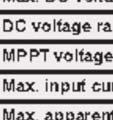
Report no GZU-001. Growatt 30000TL3-S, Growatt 30000TL3-SE. Max. input current: 34A/34A 38A/38A
|
|
|
- Lizbeth Parks
- 5 years ago
- Views:
Transcription

1
2 age 2 of 27 Rating : Model Max. DC input Voltage: 30000TL3-S, 30000TL3-SE 33000TL3-S, 33000TL3-SE Input 1000Vdc 40000TL3- NS, 40000TL3- NSE 50000TL3-S, 50000TL3-SE Max. input current: 34A/34A 38A/38A DC input range: MT Voltage Rang Vdc Vdc Vdc Vdc Nominal AC output voltage: Nominal frequency: Output 3W/N/E, 230/400Vac 50Hz 3W/E, 480Vac AC output power: 33300VA 36600VA 44400VA 53300VA Nominal AC output current: ower factor: Ingress protection: rotection Class: Operation Ambient Temp.: 3*44A 3*48A 3*58A 3*58A 0.9 Leading 0.9 Lagging I65 Class I -25 to +60


3 age 3 of 27 Report t no GZU-001 Summary of testing: Tests performed (name of test and test clause): All applicable test items. Testing location: Intertek Testing Services S Shenzhen Ltd. Guangzhou Branch Copy of marking plate(representative): Note: 1. The above markings are the minimum requirements required by thee safety standard. For the final production samples, the additional markings which o not give rise too misunderstanding may be added. 2. Label is attached on the side surface of enclosure and visible after installation 3. Other markings same as 50000TL3-S, 50000TL3-SE except model name and ratings Test item particulars...: Temperature range...: -25 C ~ 60 C Overvoltage category...: OVC I (for main) I protection class...: I65 ossible test case verdicts: - test case does not apply to the testt object... : N/A - test object does meet the requirement... : (ass) - test object does not meet the requirement : F (Fail) OVC O II (for V input) OVC O IV OVC III
4 age 4 of 27 Testing... : Date of receipt of test item... : 16 Aug., 2016 Date (s) of performance of tests... : 16 Aug., Sep., 2016 General remarks: The test results presented in this report relate only to the object tested. This report shall not be reproduced, except in full, without the written approval of the Issuing testing laboratory. "(see Enclosure #)" refers to additional information appended to the report. "(see appended table)" refers to a table appended to the report. Throughout this report a point is used as the decimal separator. Clause numbers in parentheses derive from VDE-AR-N 4105: When determining the test conclusion, the Measurement Uncertainty of test has been considered. This report is for the exclusive use of Intertek's Client and is provided pursuant to the agreement between Intertek and its Client. Intertek's responsibility and liability are limited to the terms and conditions of the agreement. Intertek assumes no liability to any party, other than to the Client in accordance with the agreement, for any loss, expense or damage occasioned by the use of this report. Only the Client is authorized to permit copying or distribution of this report and then only in its entirety. Any use of the Intertek name or one of its marks for the sale or advertisement of the tested material, product or service must first be approved in writing by Intertek. The observations and test results in this report are relevant only to the sample tested. This report by itself does not imply that the material, product, or service is or has ever been under an Intertek certification program. The test report only allows to be revised only within the report defined retention period unless standard or regulation was withdrawn or invalid.
5 age 5 of 27 General product information: roduct covered by this report is grid-connected V inverter for indoor or outdoor installation. The connection to the DC input and AC output are through terminal. The structure of the unit complied with the I 65 requirement. The inverters intended to operate at ambient temperature , which will be specified in the user manual, however, the inverters will output full power when operated at 45, if operated at high than 45 temperature, the output power would be derate. For all model, The DC startup voltage is 250Vdc, and inverter does not start when input voltage larger than 1000V For model 30000TL3-S, 30000TL3-SE, 33000TL3-S, 33000TL3-SE, 40000TL3-NS, 40000TL3-NSE, if the DC input higher than 800Vdc the output power would be derate; For model 50000TL3-S, 50000TL3-SE, if the DC input higher than 850Vdc the output power would be derate; For model 30000TL3-S, 30000TL3-SE, 33000TL3-S, 33000TL3-SE, if the DC input lower than 450Vdc the output power would be derate; For model 40000TL3-NS, 40000TL3-NSE, if the DC input lower than 540Vdc the output power would be derate; For model 50000TL3-S, 50000TL3-SE, if the DC input lower than 645Vdc the output power would be derate; All models have identical mechanical and electrical construction except some parameter of the software architecture in order to control the max output power. The detailed difference as following: Model Junction Box DC fuse ID board V string monitoring 30000TL3-S, 33000TL3-S, 40000TL3-NS, 50000TL3-S 30000TL3-SE, 33000TL3-SE, 40000TL3-NSE, 50000TL3-SE denotes incorporating this component and function. Model 30000TL3-S, 30000TL3-SE, 33000TL3-S, 33000TL3-SE, 40000TL3-NS, 40000TL3-NSE are non-isolated inverter; Model 50000TL3-S and 50000TL3-SE are isolated inverter, which output shall be connected with isolated transformer. Other than special notice, the model 40000TL3-NS is as the representative test models in this report Factory information: SHENZHEN GROWATT NEW ENERGY TECHNOLOGY CO., LTD 1st East & 3rd Floor of Building A, Building B, Jiayu Industrial ark, #28, GuangHui Road, LongTeng Community, Shiyan Street, Baoan District, Shenzhen,.R.China
6 age 6 of 27 DIN V VDE V : Clause Requirement - Test Result - Remark Verdict 4 REQUIREMENTS 4.0 General These requirements apply to integrated or separate (independent) disconnecting devices unless otherwise noted. The disconnection device has to cut off the power generating system on the ac side from the grid by two switches in series when: the voltage and/or the frequency of the grid is deviating, direct current (DC) is fed into the Grid. unintentional islanding operation occurs, intentional islanding operation using grid backup systems (emergency supplies). 4.1 Functional safety The safety must be assured under all operating conditions complying with the defined functions 4.3 to 4.6 and if applicable 4.8 of the disconnection device. The disconnection device can be an independent unit or an integrated part of the power generating unit and must switch off in case of a fault and indicate the fault status Considered, see annex. The single fault safe system was reviewed. The theoretical investigation was verified by error simulation Single fault tolerance The disconnection device must comply with the single fault tolerance requirements of VDE-AR-N 4105: , A.6 Considered, functional explanation and table 6.1 below Interface Switch The interface switch must, in case it is integrated into a V-inverter, comply with the requirements of DIN EN (VDE ): , and in all other cases with the requirements according to VDE- AR-N 4105: , 6.4. Disconnection takes place redundant through two relays and the IGBT-full bridge in series. The relays and the IGBT-full bridge are able to switch the full current. (6.4.1) General For the connection of the power generation system to the network operator s low-voltage network or to the remaining customer system, it is necessary to use an interface switch. It consists of two electric switching devices connected in series and shall thus be constructed redundantly. The interface switch is controlled by the NS protection and activates automatically if at least one protective function responds. The breaking devices of the interface switch shall be designed to be short-circuit proof and shall be releasable without delay and with due regard to the protective devices required by clause 6.5. The breaking
7 age 7 of 27 DIN V VDE V : Clause Requirement - Test Result - Remark Verdict capacity of the two breaking devices of the interface switch shall be dimensioned at least in accordance with the responding range of the upstream safety fuse or the maximum short-circuit current contribution of the power generation system. Switches with at least breaking capacity shall be use for both breaking devices of the interface switch. In addition to that, all-pole disconnection shall be ensured. (6.4.2) Central interface switch N/A The two break devices of the central interface switch shall be executed as galvanic break devices. The two break devices of the interface switch shall be installed directly at the central meter panel in the circuit distributor of the power generation system. N/A (6.4.3) Integrated interface switch Construction of the interface switch shall be carried out taking into consideration the single-fault tolerance. An interface switch ensures a single-fault tolerant allphase galvanic breaking. For power generation systems with inverters, the interface switch shall be provided on the inverter s network side. A short circuit in the inverter shall not impair the switching function of the interface switch. 4.2 Connection conditions The connection, the reconnection after a grid-fault and the reconnection after short interruption shall be carried out according to VDE-AR-N 4105: , (8.3.1) General A power generation system shall be connected to the network operator s network only if a suitable device determines that both the mains voltage and the mains frequency are within the tolerance range of 85 % Un to 110 % Un or 47.5 Hz to Hz, respectively, for a period of at least 60 seconds. If decoupling protection devices are tripped because of a short interruption, then the power generation system is permitted to already reconnect as soon as the mains voltage and mains frequency have uninterruptedly remained within the tolerance ranges given above for a period of 5 seconds. Short time interruptions are characterised by the NS protection settings of the mains frequency and/ or network voltage being exceeded or undershot for a maximum period of 3 seconds. The power generation system being reconnected to the network operator s network at the tripping of the decoupling protection device, the active power of controllable power generation systems supplied to the network operator s network shall not exceed the Tested with a variable AC- ower supply at the output. Inverter disconnects within the limits, see table 6.2 below.
8 age 8 of 27 DIN V VDE V : Clause Requirement - Test Result - Remark Verdict gradient of 10 % of the active power per minute. 4.3 Monitoring the voltage voltage drop U< The disconnection because of a voltage drop shall be carried out according to VDE-AR-N 4105: , and See appended table below rise-in-voltage U>> The disconnection because of a rise-in-voltage shall be carried out according to VDE-AR-N 4105: , and See appended table below slow rise-in-voltage U> The disconnection because of a slow rise-in-voltage (10-minute-average) shall be carried out according to VDE-AR-N 4105: , and See appended table below. 4.4 Monitoring the frequency The disconnection because of a frequency decrease or a frequency increase shall be carried out according to VDE-AR-N 4105: , and See appended table below. (6.5.1) General The purpose of the NS protection is to disconnect the power generation system from the net in the event of inadmissible voltage and frequency values. This is intended to prevent an unintentional feed-in of the power generation system into a power-supply unit separated from the remaining distribution network as well as the feed-in of faults within this network. The system operator shall himself take precautions to prevent damages to his systems and installations as might be caused by switching actions, voltage fluctuations and automatic reclosings in the network connected upstream or other process in the network of the network operator. The following functions of the decoupling protection shall be implemented: - Voltage drop protection U <; - Rise-in-voltage protection U >; - Rise-in-voltage protection U >>; - Frequency decrease protection f <; - Frequency increase protection f >; - Islanding detection. The setting values of the protective functions and the last five dated failure reports shall be readable at the NS protection. Interruptions of supply with durations of 3 s or longer shall not lead to loss of any of the failure reports. Read-out shall be possible at the central NS protection irrespective of the operational state of the
9 age 9 of 27 DIN V VDE V : Clause Requirement - Test Result - Remark Verdict power generation system and without any additional aids. For integrated NS protection read-out may be carried out using a data interface. (6.5.2) rotective functions The protective functions of the NS protection shall be designed so that the disconnection time (the sum of the proper times of NS protection and interface switch plus a delay for the protection relay, which may or may not be adjustable) does not exceed 200 ms. 4.5 Monitoring the dc current A feed in of d.c current into the low-voltage grid due to defective equipment must lead to a switch off within 0.2 seconds. For this purpose the fault itself or a measurement of the dc component of the current exceeding 1 A can be used as disconnection criteria. See appended table below. 4.6 Detection of islanding operation The disconnection because of a detection of unintended islanding operation shall be carried out according to VDE-AR-N 4105: , and See appended table below. (6.5.3) Islanding detection The islanding detection is implemented in the central NS protection or in the integrated NS protection of the power generation unit. If an islanding detection system acting on the integrated interface switch is integrated in all power generation units of a power generation system, then it is permitted to omit the islanding detection in the central NS protection regardless of the system power. Detection of an isolated network and disconnection of the power generation system by means of the interface switch shall be completed within 5 seconds. See appended table below. 4.7 Markings A generating system equipped with an automatic disconnecting device shall be marked with the information VDE which is visible from the outside. This can be done by the marking plate or showing it on a display of the disconnection device or a separate marking 4.8 Requirements for disconnection devices integrated into V-inverters The requirements of the DIN EN (VDE ): , 4.8 regarding the residual current detection and the insulation detection of the Vgenerator shall be complied with.
10 age 10 of 27 DIN V VDE V : Clause Requirement - Test Result - Remark Verdict 5 General Requirements Limits according to DIN EN (VDE ) regarding radio interferences must be complied with. For disturbance-free operation disturbance limits according to DIN EN (VDE ) shall be complied with. 6 TYE TESTING 6.0 General The following tests are valid for integrated and separated disconnecting devices unless otherwise noted. A separate disconnection device must be tested together with a suitable supply. It has to be ensured that the turn-off signal is caused by the disconnection device and not by the supply. See following test report 6.1 Functional safety The testing of the single fault tolerance and the error detection with following disconnection according to 4.1 is carried out according to DIN VDE V (VDE V ): , Connection conditions The testing of the connection and the reconnection is carried out according to DIN VDE V (VDE V 0124): , and Monitoring the voltage The testing of the voltage monitoring is carried out according to DIN VDE V (VDE V ): , Monitoring the frequency The testing of the frequency monitoring is carried out according to DIN VDE V (VDE V ): , Monitoring the dc current The testing of the disconnection due to feed in of direct current is carried out either by a) or b): a) The measuring device at the switching point (e.g. current transformer or resistance) is fed with direct current of 1 A. The cut-off must be carried out within 0.2 seconds. b) By means of a fault simulation it is measured if a defective system operation with a d.c. fault current of more than 1 A leads to cut-off within 0.2 seconds. 6.6 Detection of islanding operation The testing of the disconnection due to unintended islanding operation is carried out according to DIN VDE V (VDE V ): ,
11 age 11 of 27 DIN V VDE V : Clause Requirement - Test Result - Remark Verdict 7 Routine Test The manufacturer has to carry out routine tests regarding all safety relevant functions before delivering an automatic disconnection device. 8 Construction Specification Initial tests and re-examination in addition to the routine tests may be omitted. If the disconnection device is a separate unit it must not be used in a TN-C power system. In this case a TN-C-S power system must be created.
 and slave CU (Control B).")
12 age 12 of ( & ) TABLE: General requirements Design of functional safety: The internal control is redundant built. It consists of Microcontroller main CU (Control A) and slave CU (Control B). The main CU control the relays by switching signals; measures the V voltage, current and voltage, measures grid voltage, frequency, AC current with injected DC and the array insulation resistance to ground. In addition it tests the current sensors and the RCMU circuit before each start up. The CU (Control B) is measures the grid voltage and residual current measuring, also can switch off the relays independently, and communicate with CU (Control A) each other. The current is measured by a current sensor. The AC current signal and the injected DC current signal are sent to the main CU. The main CU tests and calibrates before each start up all current sensors. The unit provides two relays in series in all output conductors. When single fault applied to one relay, alarm an error code in display panel, another redundant relay provides basic insulation maintained between the V array and the mains. All the relays are tested before each start up. 6.1 (6.5.1) TABLE: General requirements String 1 U DC = Un 580Vdc Uac = Un 230 Vac = (W) Component No. Fault Observation Relay defect RY1 L Short before start up Error message Error: 117 (Relay fault). V inverter did not connect and feed power to grid immediately. Relay defect RY1 N Relay defect RY2 L Relay defect RY2 N Short before start up Short before start up Short before start up Error message Error: 117 (Relay fault). V inverter did not connect and feed power to grid immediately. Error message Error: 117 (Relay fault). V inverter did not connect and feed power to grid immediately. Error message Error: 117 (Relay fault). V inverter did not connect and feed power to grid immediately. GFCI Defeat of power CE protected, and disconnect from grid. Indicate Residual I High. No hazard C286 S/C CE protected, and disconnect from grid. Indicate Residual I High. No hazard Q1(2-3) S/C CE protected immediately, Error message: "Error 117". CE disconnect from the grid immediately, no output, no hazard
13 age 13 of 27 Q1(1-2) S/C CE protected immediately, Error message: "Error 117". CE disconnect from the grid immediately, no output, no hazard Grid voltage Monitoring defect Grid voltage Monitoring defect Frequency Monitoring defect Loss of control (Control B) O-C S-C O-C O-C Supplementary information: S-C: Short circuit, O-C: Open circuit During the test: Fire do not propagates beyond the EUT; Equipment do not emit molten metal; Enclosures do not deform to cause non-compliance with the standard. ass the dielectric test. Error message Error: 102 (Data received by master and slave processor are different). V inverter disconnected from grid immediately. Error message Error: 102 (Data received by master and slave processor are different). V inverter disconnected from grid immediately. Error message AC F outrange. V inverter disconnected from grid immediately LCD lighting flash. V inverter disconnected from grid immediately. 6.2 (5.5.1) Connection conditions For 40000TL3-NS DC input: AC output: Rated Output ower 580Vdc 230Vac; 50Hz 40000W Measure Item Reconnection? Reconnection Time (>60s) f ist = 47,45Hz Yes No Cannot reconnection f ist 47,55Hz Yes No 82.3s f ist = 50,1Hz Yes No Cannot reconnection f ist 50,0Hz Yes No 82.0s U ist < 85% U n Yes No Cannot reconnection U ist 85% U n Yes No 82.1s U ist > 110% U n Yes No Cannot reconnection U ist 110% U n Yes No 82.2s 6.2 (5.5.2) For 40000TL3-NS After 2s of 77% Un After 4s of 77% Un Short-time Interruption Reconnection time s 6.3s 6.4s 82.3s 82.3s 82.3s 6.3 ( ) Monitoring the voltage (Results of Voltage monitoring) For 40000TL3-NS Rated Voltage (Un) 230Vac Rated Frequency 50Hz % Un (R phase) 97.00ms ms 95.25ms 118% Un (S phase) ms 85.00ms ms
14 age 14 of % Un (T phase) 87.75ms ms ms 118% Un (RST ms ms ms phase) 77% Un (R phase) 51.75ms 51.25ms 49.00ms 77% Un (S phase) ms ms 92.75ms 77% Un (T phase) ms ms ms 77% Un (RST phase) ms ms 92.75ms 6.3 ( ) Monitoring the voltage (Results of the rotection of the Increase in Voltage as 10-min moving average) Output Voltage Switch (V) On/Off state Finally Time until Switch off (s) 100% Un On Off Work normally 112% Un On Off % Un On Off Work normally 108% Un On Off Work normally 106% Un On Off Work normally 114% Un On Off ( ) Monitoring the frequency f (Hz) Trip time (ms) f (Hz) Trip time (ms) f (Hz) Trip time (ms) Frequency decrease Frequency increase TABLE: Monitoring the dc current = 0.25 N = (W) Feed-in current = 1.0 A d.c., Cut-off current = (ms) = 0.5 N = (W) Feed-in current = 1.0 A d.c., Cut-off current = (ms) = 1.0 N = (W) Feed-in current = 1.0 A d.c., Cut-off current = (ms) 10000W 40.25ms 20000W 40.75ms 40000W 40.25ms
15 age 15 of 27 Report No GZU (5.4.6) TABLE: Detection of islanding operation Test conditions: Frequency: 50+/-0,2Hz UN=230+/-3Vac RLC consumes inverter real power within +/-3% Distortion factor of chokes <3% Quality Q>2 = 1.0 N = (W) 40000W = 0.5 N = (W) 20000W = 0.25 N = (W) 10000W QL = 81428Var Cut-off time (ms) QL = 40253Var Cut-off time (ms) QL = 20710Var Cut-off time (ms) 95% % % % % % % % % % % % % % % % % % % % % % % % % % % % % % % % % 69.5


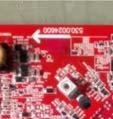
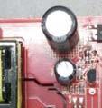
16 age 16 of 27 Report R No GZU-001 Appendix photos Top view of 50000TL3-S, 40000TL3-NS, 33000TL3-S3, 30000TL3-S Top view of the models 50000TL3-SE, 40000TL3-NSE, 33000TL3-SE, 30000TL3- SE


17 age 17 of 27 Report No GZU-001 Side view of the models 50000TL3-SE, 40000TL3-NSE, 33000TL3-SE, 30000TL3- SE Buttom view for all models

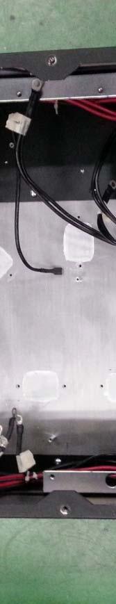
18 age 18 of 27 Report No GZU-001 Internal view of 50000TL3-S, 40000TL3-NS, 33000TL3-S, 30000TL3-S Internal view of 50000TL3-SE, 40000TL3-NSE, 33000TL3-SE, 30000TL3-SE


19 age 19 of 27 Report No GZU-001 Internal view of 50000TL3-S, 40000TL3-NS, 33000TL3-S, 30000TL3-S Internal view of 50000TL3-S, 40000TL3-NS, 33000TL3-S, 30000TL3-S


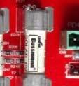


20 age 20 of 27 Report R No GZU-001 Internal view (for all models) V string monitoring board (for model 50000TL3-S, 40000TL3-NS, 33000TL3-S, 30000TL3-S)


21 age 21 of 27 Report R No GZU-001 Soldering view of V string monitoring board (for model 50000TL3-S, 40000TL3-NS, 33000TL3-S, 30000TL3-S) IO board view (for all models)


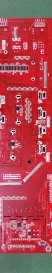


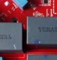


22 age 22 of 27 Report R No GZU-001 Soldering vieww of IO board (for all models) Main board view (for all models)


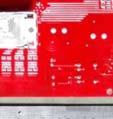


23 age 23 of 27 Report R No GZU-001 Soldering vieww of main board (for all models) ID board view (for model 50000TL3-S, 40000TL3-NS, 33000TL3-S, 30000TL3-S)


24 age 24 of 27 Report R No GZU-001 Back view of ID board (for model 50000TL3-S, 40000TL3-NS, 33000TL3-S, 30000TL3-S) Display board view (for all models)


25 age 25 of 27 Report R No GZU-001 Back view of display board (for all models) AC outputt board for model 50000TL3-SE, 40000TL3-NSE, 33000TL3-SE, 30000TL3-SE


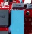
26 age 26 of 27 LCL inductor view (for model 50000TL3-S, 40000TL3-NS, 33000TL3-S, 30000TL3-S) Soldering view of LCL inductor (for model 50000TL3-S, 40000TL3-NS, 33000TL3- S, 30000TL3-S)

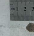
27 age 27 of 27 Earthing terminal of the unit End of report
TEST REPORT DIN V VDE V :2006 Automatic disconnecting device
 age 1 of 23 TEST REORT Automatic disconnecting device Report Reference No...: GZ10080033-1 Date of issue...: August 18, 2010 Total number of pages... 23 pages Testing Laboratory...: Address...: Tested
Summary of testing: Testing location: Intertek Testing Services Taiwan Ltd.
 age 2 of 40 Summary of testing: Tests performed (name of test and test clause): 5.4.3 System reactions flicker 5.4.4 System reactions harmonics and interharmonics 5.4.9 System reactions precautionary measures
Page 1 of 28. Ingo Röhr. Frank Hesmer
 Page 1 of 28 TEST REPORT Engineering recommendation G83/1 Recommendation for the connection of small-scale embedded generators (up to 16 A per phase) in parallel with public low-voltage distribution networks.
TEST REPORT AS :2005 and AS :2005 Grid connection of energy systems via inverters Grid protection requirements
 TEST REPORT AS 4777.2:2005 and AS 4777.3:2005 Grid connection of energy systems via inverters Grid protection requirements Report reference No...: 09TH0459-AS4777_2 Tested by (printed name and signature)...:
TEST REPORT. : The submitted samples complied with the above EMC standards. TRF No.: AS NZS (2012)-b
-b") TEST REPORT Applicant Name & Address Manufacturing Site Sample Description Product Model No. : Shenzhen SOFARSOLAR Co., Ltd. 3A-1, Huake Building, East Technology Park, Qiaoxiang Road, Nanshan District,
TEST REPORT Applicant Name & Address Manufacturing Site Sample Description Product Model No. : Shenzhen SOFARSOLAR Co., Ltd. 3A-1, Huake Building, East Technology Park, Qiaoxiang Road, Nanshan District,
Page 2 of 69 VDE Report No.: / DC - DC Converter for building in. TDK Innoveta Inc. iba - Series (see model matrix appendix 1)
") Page 2 of 69 VDE Report No.: 2520400-3336-0009/132550 Test item description... : Trade Mark...: Manufacturer...: Model/Type reference...: Serial Number..: Ratings...: Input: Output: Ambient: DC - DC Converter
Page 2 of 69 VDE Report No.: 2520400-3336-0009/132550 Test item description... : Trade Mark...: Manufacturer...: Model/Type reference...: Serial Number..: Ratings...: Input: Output: Ambient: DC - DC Converter
Consumer Products Services Germany GmbH Türkheim Germany
 TEST REPORT SUMMARY Nota de interpretación técnica de la equivalencia de la separación galvanica de la conexión de instalaciones Generadoras en baja tension Sobre conexión de instalaciones fotovoltaicas
REQUIREMENTS FOR DIRECTIONAL LAMPS, LIGHT EMITTING DIODE LAMPS AND RELATED EQUIPMENT ACCORDING TO THE EC REGULATION 1194/2012
 2/F., Garment Centre, 576 Castle Peak Road, Kowloon, Hong Kong. Telephone: (852) 2173 8888 Facsimile: (852) 2785 5487 www.intertek.com REQUIREMENTS FOR DIRECTIONAL LAMPS, LIGHT EMITTING DIODE LAMPS AND
Troubleshooting for Growatt TL&MTL. (Ver1.2)
") Troubleshooting for Growatt TL&MTL (Ver1.2) 2013-7-15 Version Date Note Ver1.1 2013.7.15 First draft Ver1.2 2013.7.29 Remove Hungary in Country code list table, Hungary choose VDE 0126 Content General...
Troubleshooting for Growatt TL&MTL (Ver1.2) 2013-7-15 Version Date Note Ver1.1 2013.7.15 First draft Ver1.2 2013.7.29 Remove Hungary in Country code list table, Hungary choose VDE 0126 Content General...
TEST REPORT IEC Information technology equipment Safety Part 1: General requirements
 Test Report issued under the responsibility of: TEST REPORT IEC 60950-1 Information technology equipment Safety Part 1: General requirements Report Number.... : 207721-AS3-1 CB/DE1-55140 Date of issue...
UL TEST REPORT AND PROCEDURE
 Issue Date: 2010-05-31 Page 1 of 27 Report Reference # E122103-A38-UL UL TEST REPORT AND PROCEDURE Standard: Certification Type: CCN: UL 60950-1, 2nd Edition, 2007-03-27 (Information Technology Equipment
TEST REPORT IEC Information technology equipment Safety Part 1: General requirements
 Test Report issued under the responsibility of: TEST REPORT IEC 60950-1 Information technology equipment Safety Part 1: General requirements Report Number.... : 210282-CI3-2 CB DE1-56459 Date of issue...
Page 2 of 8 Report No.:
 Page 2 of 8 Report No.: 11016970 002 Copy of marking plate: Summary of testing: The maximum operating temperature which specified by manufacturer is +40 C. Highest load for this equipment according to
 Page 4 of 8 Report No. 11029568 003 Summary of testing: Tests performed (name of test and test clause): All applicable tests as described in Test Case and Measurement Sections were performed. Tests performed
DP&L s Technical Requirements for Interconnection and Parallel Operation of Distributed Generation
 DP&L s Technical Requirements for Interconnection and Parallel Operation of Distributed Generation Technical Requirements for Interconnection and Parallel Operation of Distributed Generation Single Phase
INTERIM ARRANGEMENTS FOR GRID TIED DISTRIBUTED ENERGY RESOURCES. Technical Requirements for Grid-Tied DERs
 INTERIM ARRANGEMENTS FOR GRID TIED DISTRIBUTED ENERGY RESOURCES Technical Requirements for Grid-Tied DERs Projects Division 6/29/2017 Contents 1 Definitions and Acronyms... 1 2 Technical Interconnection
EMC VERIFICATION SUMMARY Report No.: SZHH
 EMC VERIFICATION SUMMARY Toy ITE Others Additional Models: 0801 to 0899 INCLUSIVE, 0804, 0804W, 0805, 0806, 0807, 0808, 0809, 0811, 0811W, 0812, 0813, 0814,0815, 0816, 0817,0817 ROOM 619, 6/F. PENINSULA
Harmonic current emissions as per EN
 POWER QUALITY Harmonic current emissions as per EN 61000-3-2 Harmonic Test Value in Amps % of fund Limit in Amps 2 0.014 0.16 1.080 3 0.099 1.14 2.300 4 0.009 0.10 0.430 5 0.040 0.46 1.140 6 0.015 0.17
Company Directive STANDARD TECHNIQUE: SD1E/2. Technical Requirements for Customer Export Limiting Schemes
 Company Directive STANDARD TECHNIQUE: SD1E/2 Technical Requirements for Customer Export Limiting Schemes Policy Summary This Standard Technique specifies the requirements for customer owned Export Limitation
Amendment to Test Report
 Test Report issued under the responsibility of www.nemko.com Amendment to Test Report This Amendment is valid only together with the main Test Report Report No.... : 270292 Main Report No.... : 261294
Auftrags-Nr.: Order No.:
 www.tuv.com age 2 of 12 Report No.: 16064278 004 rüfbericht-nr.: Test Report No.: 16064278 004 Auftrags-Nr.: Order No.: 174037713 Seite 2 von 12 age 2 of 12 Sonstiges/ Other Aspects: - This report is based
PHOENIX CONTACT - 06/2008. Features. DANGER OF EXPLOSION! Only remove equipment when it is disconnected and not in the potentially explosive area.
 Primary-switched power supply with SFB technology, 1 AC, output current 20 A INTERFACE Data Sheet 103383_en_00 1 Description PHOENIX CONTACT - 06/2008 Features QUINT POWER power supply units highest system
PHOENIX CONTACT - 05/2008. DANGER OF EXPLOSION! Remove an item only when it is not connected to power or if it is located in the non-explosive area.
 Primary-switched power supply with SFB technology, 1 AC, output current 20 A INTERFACE Data Sheet 103129_en_01 PHOENIX CONTACT - 05/2008 1 Description QUINT POWER power supply units highest system availability
TEST REPORT IEC Audio, video and similar electronic apparatus - Safety requirements
 Test Report issued under the responsibility of www.nemko.com TEST REPORT IEC 60065 Audio, video and similar electronic apparatus - Safety requirements Report Number... : 246847 Date of issue... : October
TEST REPORT IEC Information technology equipment Safety Part 1: General requirements
 Test Report issued under the responsibility of: TEST REPORT IEC 60950-1 Information technology equipment Safety Part 1: General requirements Report Number.... : 212475-CI3-1 CBDE1-52299/A1/M1 Date of issue...
Growatt 4000 UE / 5000 UE / 6000 UE
 Growatt 4000 UE / 5000 UE / 6000 UE Leading - edge Technology 6k efficiency 98% DC input voltage up to 800V 97% Maximum efficiency of 97.9% 96% 95% Internal DC switch 94% Transformerless 93% 92% Compact
TEST REPORT IEC Uninterruptible power systems Part 3: Method of specifying the performance and test requirements
 Test Report issued under the responsibility of: TEST REORT IEC 62040-3 Uninterruptible power systems art 3: Method of specifying the performance and test requirements Report reference No...: 11-EL-0026.06
Technical Requirements for Connecting Small Scale PV (sspv) Systems to Low Voltage Distribution Networks
 Systems to Low Voltage Distribution Networks") 2014 Technical Requirements for Connecting Small Scale PV (sspv) Systems to Low Voltage Distribution Networks This document specifies the technical requirement for connecting sspv to the low voltage distribution
2014 Technical Requirements for Connecting Small Scale PV (sspv) Systems to Low Voltage Distribution Networks This document specifies the technical requirement for connecting sspv to the low voltage distribution
CONEXT TL 20000E Schneider Electric Ltd. China KW %!! $! % & TD110826C01 and PVAU110826C01 Bureau Veritas CONEXT TL 15000E E
 %!! 9213202265 CONEXT TL 20000E Schneider Electric Ltd. China 15-20 KW Inverter requirementsart 2 Grid protection requirements - art 3 standards for Grid Connection of Inverter SystemsSI 4777 / AS 4777
TEST REPORT. ASTM E648-14c Standard Test Method for Critical Radiant Flux of Floor-Covering Systems Using a Radiant Heat Energy Source
 ASTM E648-14c Standard Test Method for Critical Radiant Flux of Floor-Covering Systems Using a Radiant Heat Energy Source TEST REPORT Intertek Testing Services NA, Inc. 16015 Shady Falls Road Elmendorf,
DE Total. American Inc. IEC Test Report Form. If this. and appended to General disclaimer: the NCB, VDE File. No VDE File.
 1Fdar Test Report issued under the responsibility of: TEST REPORT IEC 60950-1 Information technology equipment Safety Part 1: General requirements Report Number....: 215009-CI3-1 Date of issue...: 2015-07-31
TEST REPORT EN 62233: 2008 Measurement methods for electromagnetic fields of household appliances and similar apparatus with regard to human exposure
 TEST REORT Measurement methods for electromagnetic fields of household appliances and similar apparatus with regard to human exposure Report Reference No....: GZES110400210331 Tested by (name + signature)...:
TEST REPORT IEC Part 2: Particular requirements Section Thirteen d.c. or a.c. supplied electronic controlgear for LED modules
 age 1 of 31 Test Report issued under the responsibility of: Intertek Testing Services Shenzhen Ltd. Guangzhou Branch TEST REORT art 2: articular requirements Section Thirteen d.c. or a.c. supplied electronic
Test Report. File No.: SHV04007/15-02 Test Report No.: , P.R. China
 Applicant... : Manufacturer... : Order No.... : Zhejiang ERA Solar Technology Co., Ltd. Sihai Road, Huangyan Economic Development Zone, Taizhou, Zhejiang 318020, P.R. China Zhejiang ERA Solar Technology
page 2 of 86 Report reference No:
 articulars: test item vs. test requirements 3. Classification 3.1. Utilization category: (A or B)... : A 3.2. Interruption medium: (air, vacuum, gas Break)... : Air 3.3. Design: (open construction, moulded
Tel: Fax:
 Grid Tie Solar Inverter Operator's Manual SG-4000 1 IMPORTANT SAFETY INSTRUCTIONS SAVE THESE INSTRUCTIONS To reduce the risk of electrical shock and to ensure safe installation and operation of Grid Tie
Test Report. File No.: SHV01023/16 Test Report No.: Taizhou, Zhejiang , P.R. China
 Applicant... : Manufacturer... : Order No.... : Zhejiang ERA Solar Technology Co., Ltd. Sihai Road, Huangyan Economic Development Zone Taizhou, Zhejiang 318020, P.R. China Zhejiang ERA Solar Technology
Orbital GFI Inverter Series
 Orbital GFI Inverter Series Datasheet Key Features One, split or three phases and up to 25 kva Superior efficiency of 95% CAN Bus control and DAQ Power quality and EMC compliance in accordance with European
MINI-PS AC/24DC/1.3
 Power supply unit INTERFACE Data sheet 102894_en_03 1 Description PHOENIX CONTACT 2015-11-17 Features MINI POWER power supplies for MCR technology In measurement and control technology (MCR), modular electronics
QUINT-PS/ 1AC/24DC/20
 Primary-switched power supply with SFB technology, 1 AC, output current 20 A INTERFACE Data sheet 103129_en_04 1 Description PHOENIX CONTACT - 02/2010 Features QUINT POWER power supply units Maximum system
REPORT NO. DL TYPE TEST REPORT OF A ELECTROMAGNETIC RELAY RENDERED TO
 Page 1 of 23 Job No. DL1206178. REPORT NO. DL1206178-001 TYPE TEST REPORT OF A ELECTROMAGNETIC RELAY RENDERED TO M/s. Paramount Industries No 70, 5 th Cross, SSI Area, Rajajinagar, Bangalore - 560 010
TEST REPORT IEC Information technology equipment Safety Part 1: General requirements
 Test Report issued under the responsibility of www.nemko.com TEST REPORT IEC 60950-1 Information technology equipment Safety Part 1: General requirements Report Number....: 285573 Date of issue...: 2015-09-15
Switching power supplies CP range, Linear power supplies CP-L range. Content
 CP range, Linear power supplies CP-L range Content Switching power supplies, primary switch mode, CP range Benefits and advantages... 136 Approvals... 137 Ordering details... 138 Technical data... 11 Dimensional
QUINT-PS/ 3AC/24DC/10
 Primary-switched power supply with SFB technology, 3 AC, output current 10 A INTERFACE Data sheet 103131_en_01 1 Description PHOENIX CONTACT - 09/2009 Features QUINT POWER power supply units Maximum system
DPM - Mesta Electronics, Inc. Low Voltage Active Harmonic Filters
 DPM - Mesta Electronics, Inc. Low Voltage Active Harmonic Filters Section [26 35 26][16280] Active Harmonic Filters (Low Voltage) Part 1 General 1.1 Summary A. Scope: Provide design and engineering, labor,
Electronic relays. Monitoring. Monitoring
 Electronic relays Neither overload nor underload are particularly good for machines and installations in industrial applications. An unsteady power supply may lead to machine failure and, thus, expensive
TEST REPORT IEC Part 2: Particular requirements Section Thirteen d.c. or a.c. supplied electronic controlgear for LED modules
 age 1 of 32 Test Report issued under the responsibility of: Intertek Testing Services Shenzhen Ltd. Guangzhou Branch TEST REORT art 2: articular requirements Section Thirteen d.c. or a.c. supplied electronic
E N G I N E E R I N G M A N U A L
 1 1 1.0 PURPOSE The purpose of this document is to define policy and provide engineering guidelines for the AP operating companies (Monongahela Power Company, The Potomac Edison Company, and West Penn
BED INTERCONNECTION TECHNICAL REQUIREMENTS
 BED INTERCONNECTION TECHNICAL REQUIREMENTS By Enis Šehović, P.E. 2/11/2016 Revised 5/19/2016 A. TABLE OF CONTENTS B. Interconnection Processes... 2 1. Vermont Public Service Board (PSB) Rule 5.500... 2
TEST REPORT IEC Part 2: Particular requirements Section Thirteen d.c. or a.c. supplied electronic controlgear for LED modules
 age 1 of 38 Test Report issued under the responsibility of: Intertek Testing Services Shenzhen Ltd. Guangzhou Branch TEST REORT art 2: articular requirements Section Thirteen d.c. or a.c. supplied electronic
TEST REPORT IEC Safety of laser products - Part 1: Equipment classification and requirements
 Test Report issued under the responsibility of: TEST REPORT IEC 60825-1 Safety of laser products - Part 1: Equipment classification and requirements Report Number.... : GZES160801248631 Date of issue...
UL TEST REPORT AND PROCEDURE
 Issue Date: 2013-10-30 Page 1 of 19 Report Reference # E122103-A151-UL UL TEST REPORT AND PROCEDURE Standard: Certification Type: CCN: Complementary CCN: Product: Model: Rating: Applicant Name and Address:
TEST REPORT IEC60950_1F. Information technology equipment - Safety - Part 1: General requirements
 Issue Date: 2017-05-23 Page 1 of 9 Report Reference # 4787989179 Test Report issued under the responsibility of: TEST REPORT IEC 60950-1 Information technology equipment - Safety - Part 1: General requirements
Test Report. File No.: SHV01032/18-02 Test Report No.:
 File No.: SHV01032/18-02 No.: 492011003.001 Applicant... : Manufacturer 1... : Manufacturer 2... : Order No.... : Suzhou Akcome Optronics Science &Technology Co., Ltd. Jintang Rd, Zhangjiagang Economic
TEST REPORT IEC Low-voltage switchgear and controlgear - Part 2: Circuit-breakers
 Test Report issued under the responsibility of: TEST REORT Low-voltage switchgear and controlgear - art 2: Circuit-breakers Report Reference No.... : 3305316.50 Date of issue... : 2013-09-17 Total number
TS RES - OUTSTANDING ISSUES
 TS RES - OUTSTANDING ISSUES This document has been officially issued as DRAFT until the following outstanding issues have been resolved. At that time the document will be officially reissued as the next
EMC TEST REPORT. Report No.: TS EME Model No.: 33XR-A Issued Date: Jan. 08, 2009
 Page 1 of 18 EMC TEST REPORT Report No.: TS08100063-EME Model No.: 33XR-A Issued Date: Jan. 08, 2009 Applicant: Test Method/ Standard: Test By: FLUKE CORP. 6920 Seaway Blvd, M/S 266D Everett, WA 98203
SPECIFIC TECHNICAL CRITERIA
 Issue Date: 2007-10-24 Page 1 of 6 Report Reference # E210157-A29-UL-1 SPECIFIC TECHNICAL CRITERIA UL 60950-1, First Edition Information technology equipment - Safety- Part 1: General Requirements Report
/ Maximum flexibility for the applications of tomorrow. / Open data communication. / Smart Grid Ready
 / Battery Charging Systems / Welding Technology / Solar Electronics FRONIUS SYMO / Maximum flexibility for the applications of tomorrow. / PC board replacement process / Mounting system / WLAN interface
TEST REPORT IEC : 2005 (2nd Edition) and/or EN :2006 Information technology equipment Safety Part 1: General requirements
 and/or EN :2006 Information technology equipment Safety Part 1: General requirements") Test Report issued under the responsibility of: TEST REPORT IEC 60950-1: 2005 (2nd Edition) and/or EN 60950-1:2006 Information technology equipment Safety Part 1: General requirements Report Reference
Test Report issued under the responsibility of: TEST REPORT IEC 60950-1: 2005 (2nd Edition) and/or EN 60950-1:2006 Information technology equipment Safety Part 1: General requirements Report Reference
EMC TEST REPORT. NORTE SIRIUS ENTERPRISE CO., LTD , Shin-Sheng St., Chung-Ho Dist, New Taipei City, Taiwan
 Page 1 of 32 EMC TEST REPORT Report No.: TS11020117-EME Model No.: NS-PSE, NS-POINTED, NS-PSQUARE, NS-PF-S, NS-PT, NS-PR, NS-PU, NS-PF-H, NS-BALIBA, NS-FLEXMA Issued Date: Mar. 01, 2011 Applicant: NORTE
Marking label of DelSolar module type D6M240B3A
 age 2 of 19 Report Ref. No. 61.410.11.029.01 Summary of testing: Tests performed (name of test and test clause): Testing location: Clause 6, Initial measurements: - Visual inspection - Maximum power determination
ISO Rules Part 500 Facilities Division 502 Technical Requirements Section Aggregated Generating Facilities Technical Requirements
 Division 502 Technical Applicability 1(1) Section 502.1 applies to: Expedited Filing Draft August 22, 2017 the legal owner of an aggregated generating facility directly connected to the transmission system
TEST REPORT IEC Information technology equipment - Safety - Part 1: General requirements
 Issue Date: 2015-02-26 Page 1 of 61 Report Reference # E122103-A161-CB-1 Test Report issued under the responsibility of: Report Reference No... : TEST REPORT IEC 60950-1 Information technology equipment
Type CP-S, CP-C & CP-A Switch mode
 Switch mode power CP-S, CP-C & CP-A Switch mode Characteristics CP-S and CP-C range Output current 5 A, 10 A and 20 A Integrated power reserve of up to 50 % 5 A and 10 A devices with pluggable connecting
S11 Adjustable Speed Drive Engineering Specification
 PART 1 - GENERAL 1.0 Scope This specification shall cover Toshiba S11 AC Variable Frequency Drives, 6 pulse for 3- phase 200-240VAC, 380-500VAC and single phase 200V to 240VAC. 1.1 References A. National
PACSystems* RX3i and Series 90-30
 May 2012 PACSystems* RX3i and Series 90-30 Series 90*-30 Analog Output Module, Current/Voltage, 8 Channel, IC693ALG392 RX3i Analog Output Module, Current/Voltage, 8 Channel, IC694ALG392 The PACSystems
ADC5000 SERIES. AC/DC Switch Mode Power Supplies and Rectifiers for Industrial and Telecom Applications. 60W, 125W and 250 W
 ADC5000 SERIES AC/DC Switch Mode Power Supplies and Rectifiers for Industrial and Telecom Applications 60W, 125W and 250 W Input voltage 230/115 VAC voltages 12, 24, 36 or 48 VDC Statistical MTBF >3 000
QUINT-PS/ 3AC/24DC/40
 Primary-switched power supply unit with SFB technology, 3 AC, output current 40 A INTERFACE Data sheet 103133_en_00 1 Description PHOENIX CONTACT - 07/2009 Features QUINT POWER power supply units Maximum
TEST SUMMARY. Prüfbericht - Nr.: Test Report No.: Seite 2 von 25. Page 2 of 25
 15072259 001 Seite 2 von 25 Page 2 of 25 TEST SUMMARY 4.1.1 HARMONICS ON AC MAINS 4.1.2 VOLTAGE FLUCTUATIONS ON AC MAINS 4.1.3 MAINS TERMINAL CONTINUOUS DISTURBANCE VOLTAGE 4.1.4 DISCONTINUOUS INTERFERENCE
UL TEST REPORT AND PROCEDURE
 Issue Date: 2009-06-09 Page 1 of 9 Report Reference # E186249-A100- TEST REPORT AND PROCEDURE Standard: Certification Type: CCN: 60950-1, 2nd Edition, 2007-03-27 (Information Technology Equipment - Safety
EMC Test report for LED Panel Light Models , , , , ,
 4326247.50 EMC Test report for LED Panel Light Models 000529, 000530, 000531, 000532, 000535, 000536 Guangzhou, date of issue: 2016-02-24 Author:Jazz Liang By order of Marvo Verlichting B.V. at Hoogeveen,
QUINT-PS AC/24DC/40
 Power supply unit INTERFACE Data sheet 102315_en_02 1 Description PHOENIX CONTACT 2010-04-23 Features QUINT POWER power supply units for plant and special engineering reliably start heavy loads with high
VF-nC1 Adjustable Speed Drive Engineering Specification
 PART 1 - GENERAL 1.0 Scope This specification shall cover Toshiba VF-nC1 AC Variable Frequency Drives, 6 pulse for 100V single-phase 0.1 to 0.75kW, 200V single-phase 0.2 to 2.2kW and 200V threephase 0.1
LL-105-R LED Dimmer & 0-10V Bridge Setup Guide
 www.i2systems.com i2systems is a registered trademark of Integrated Illumination Systems, Inc. LightLink is a trademark of Integrated Illumination Systems, Inc. 2018 Integrated Illumination Systems, Inc.
International Maritime Organization (IMO) Fire Test Procedures (FTP) Code Part 5 and 6
 Fire Test Procedures (FTP) Code Part 5 and 6") Page 1 of 20 International Maritime Organization (IMO) Fire Test Procedures (FTP) Code Part 5 and 6 Temp-Coat 101 Project No. 100368576SAT-002.1A April 28, 2011 Prepared for: Temp-Coat Brand Products LLC
Page 1 of 20 International Maritime Organization (IMO) Fire Test Procedures (FTP) Code Part 5 and 6 Temp-Coat 101 Project No. 100368576SAT-002.1A April 28, 2011 Prepared for: Temp-Coat Brand Products LLC
Model Number Structure
 Current Sensor CSM DS_E Solid-state, Plug-in Current Sensor Applicable to motor overcurrent protection and 3-phase AC current detection. Inverse-type, start-up lock type, and instantaneous type overcurrent
Power supply CP-E 24/2.5
 2CDC 271 015 F0t06 a OUTPUT L+, L : terminals output b DC OK: terminal signalling output c INPUT L, N, PE: terminals input d OUTPUT OK: green LED output voltage OK e OUTPUT Adjust: potentiometer adjustment
Device Under Test: ALTEA VS- 24-I VS-24-I. 0 24/09/12 First issue A. Peretto L. Peretto 1 24/06/16 All text review E. Scala L. Peretto J. L.
 /9 TECHNICAL SPECIFICATIONS VOLTAGE LOW-POWER TRANSFORMER VS- Rev. Date Revision Description Prepared by Checked by Approved by 0 24/09/2 First issue A. Peretto L. Peretto 24/06/6 All text review E. Scala
Current monitor Type C 551
 Current monitor Type C 551 Relay for current monitoring, single-phase Monitoring AC and DC for overcurrent or undercurrent 1 yellow LED for indication of the relay state 1 green LED for indication of the
TEST SUMMARY. Prüfbericht - Nr.: Test Report No.: Seite 2 von 27. Page 2 of 27
 15072768 001 Seite 2 von 27 Page 2 of 27 TEST SUMMARY 4.1.1 HARMONICS ON AC MAINS 4.1.2 VOLTAGE CHANGES, VOLTAGE FLUCTUATIONS AND FLICKER ON AC MAINS 4.1.3 MAINS TERMINAL CONTINUOUS DISTURBANCE VOLTAGE
Description. Annexe to: IECEx CML X Issue 1. Isolating Amplifier D461
 October 13, 2017 Annexe to: IECEx CML 15.0063X Issue 1 Applicant: Apparatus: Braun GmbH Isolating Amplifier D461 Description The Isolating Amplifier D461 is an intrinsic safety associated apparatus
Power supply CP-E 24/20.0
 2CDC 271 027 F0008 a OUTPUT L+, L+, L, L-: terminals output b INPUT L, N, PE: terminals input c 13-14: terminals - signalling contact d OUTPUT OK: green LED output voltage OK e OUTPUT LOW: red LED output
By order of ZHONGSHAN LIANGYI LIGHTING CO., LTD. at Zhongshan, China
 4317137.50 EMC Test report for LED Fixed luminaires Models LED12036-1R, LED12036-2TU, LED120363R, LED12036-4TU2, LED12036-6TR, LED12036-1R CHR, LED12036-2TU CHR, LED12036-3R CHR, LED12036-4TU2 CHR, LED12036-6TR
Temperature monitoring relays CM-TCS Monitoring relays for monitoring temperatures with a PT100 sensor (2- or 3-wire connection)
") Data sheet Temperature monitoring relays CM-TCS Monitoring relays for monitoring temperatures with a PT100 sensor (2- or 3-wire connection) The temperature monitoring relays CM-TCS monitor overtemperature,
Data sheet Temperature monitoring relays CM-TCS Monitoring relays for monitoring temperatures with a PT100 sensor (2- or 3-wire connection) The temperature monitoring relays CM-TCS monitor overtemperature,
TECHNICAL DATA FRONIUS SYMO ( M, M, M, M, M)
") TECHNICAL DATA FRONIUS SYMO (10.0-3-M, 12.5-3-M, 15.0-3-M, 17.5-3-M, 20.0-3-M) INPUT DATA SYMO 10.0-3-M SYMO 12.5-3-M SYMO 15.0-3-M SYMO 17.5-3-M SYMO 20.0-3-M Max. input current (I dc max 1 / I dc max
TECHNICAL DATA FRONIUS SYMO (10.0-3-M, 12.5-3-M, 15.0-3-M, 17.5-3-M, 20.0-3-M) INPUT DATA SYMO 10.0-3-M SYMO 12.5-3-M SYMO 15.0-3-M SYMO 17.5-3-M SYMO 20.0-3-M Max. input current (I dc max 1 / I dc max
TEST REPORT IEC Information technology equipment - Safety - Part 1: General requirements
 Issue Date: 2015-08-10 Page 1 of 27 Report Reference # E122103-A152-CB-2 Test Report issued under the responsibility of: Report Reference No... : TEST REPORT IEC 60950-1 Information technology equipment
TEST REPORT. ASTM E648 Standard Test Method for Critical Radiant Flux of Floor-Covering Systems Using a Radiant Heat Energy Source
 ASTM E648 Standard Test Method for Critical Radiant Flux of Floor-Covering Systems Using a Radiant Heat Energy Source TEST REPORT Self Adhesive Vinyl; ID: panorama Walk & Wall Project No. 101611878SAT-001A
MINI-PS AC/2X15DC/1
 MII-PS-100-240AC/2X15DC/1 Power supply unit ITERFACE Data sheet 100299_en_04 1 Description PHOEIX COTACT - 2010-10-20 Features MII POWER is the extremely slim power supply unit with constructional widths
TEST REPORT IEC Information technology equipment - Safety - Part 1: General requirements
 Issue Date: 2017-05-23 Page 1 of 9 Report Reference # 4787989180 Test Report issued under the responsibility of: TEST REPORT IEC 60950-1 Information technology equipment - Safety - Part 1: General requirements
Instructions for D64RPB30 Series C1 Ground Fault Relay
 Instructions for D64RPB30 Series C1 Ground Fault Relay Cat. No. D64RPB30 CT 24-240V AC / DC N.C. N.O. 1 2 3 4 5 6 7 8 ON F2024-01-01 FLASHES: 1 = E/F 2 = S/C 3 = BACKUP 4 = CT 5 = F/S CV LOSS CONT = TRIP
Grid Radar Installation Manual
 Grid Radar Installation Manual MODELS GN-RD-001 120V Single Phase / Wye, 240V Single Phase, with Neutral GN-RD-002 277V 3-Phase Wye, with Neutral GN-RD-003 480V 3-Phase Delta, no Neutral GN-RD-004 208V
TEST REPORT IEC Safety of Transportable Motor-Operated Power Tools
 Test Report issued under the responsibility of: STAYER IBÉRICA S.A TEST REPORT Safety of Transportable Motor-Operated Power Tools REPORT IDS TR_POTENZA160_SEG_01 Report Reference No. : TR_POTENZA160_SEG_01
ECM3 EARTH CONTINUITY RELAY
 TECHNICAL DATASHEET ECM3 EARTH CONTINUITY RELAY Electrical Protection for Hard Rock Mines Application The ECM3 has been designed to provide earth continuity protection for cables containing pilot cores.
EESTOR INC. TEST REPORT
 EESTOR INC. SCOPE OF WORK Performance testing of capacitive samples (Ceramic samples called 361-1, 358-4, 358-5) REPORT NUMBER 103362995DAL-003 ISSUE DATE 29-JAN-2018 REVISION DATE 28-FEB-2018 PAGES 6
Sunways Solar Inverters NT 2500, NT 3000, NT 3700, NT 4200 and NT 5000 AC output: 2.5 to 5.0 kw
 Sunways Solar Inverters NT 2500, NT 3000, NT 3700, NT 4200 and NT 5000 AC output: 2.5 to 5.0 kw The tried and tested NT series has been completely reengineered and impresses with further improved performance
Original operating instructions Fail-safe inductive sensor GM504S / / 2010
 Original operating instructions Fail-safe inductive sensor GM504S 704070 / 01 06 / 2010 Contents 1 Preliminary note 3 1.1 Explanation of symbols 3 2 Safety instructions 4 2.1 Safety-related requirements
TECHNICAL DATA FRONIUS SYMO (3.0-3-S, S, S, M, M, M)
") / Perfect Welding / Solar Energy / Perfect Charging FRONIUS Symo Maximum flexibility for the applications of tomorrow N 1 W E S SnapINverter technology Integrated data communication Dynamic Peak Manager
/ Perfect Welding / Solar Energy / Perfect Charging FRONIUS Symo Maximum flexibility for the applications of tomorrow N 1 W E S SnapINverter technology Integrated data communication Dynamic Peak Manager
Power supply CP-T 24/20.0 Primary switch mode power supply
 Data sheet Power supply CP-T 24/20.0 Primary switch mode power supply The CP-T range of three-phase power supply units is the youngest member of ABB s power supply family. In terms of design and functionality,
Earth Leakage Monitoring System IsoBase IsoHub IsoOut
 2014 11 21 Earth Leakage Monitoring System IsoBase IsoHub IsoOut User Manual Due to our policy of continual improvement, specifications may change without prior notice Page 2 (34) Contents Earth Leakage