EXPERIMENTAL STUDY AND COMPARATIVE ANALYSIS OF TRANSFORMER HARMONIC BEHAVIOUR UNDER LINEAR AND NONLINEAR LOAD CONDITIONS
|
|
|
- Annice Lamb
- 5 years ago
- Views:
Transcription
1 EXPERIMENTAL STUDY AND COMPARATIVE ANALYSIS OF TRANSFORMER HARMONIC BEHAVIOUR UNDER LINEAR AND NONLINEAR LOAD CONDITIONS A THESIS SUBMITTED TO THE GRADUATE SCHOOL OF APPLIED SCIENCES OF NEAR EAST UNIVERSITY By AHMED AL BARRAWI In Partial Fulfillment of the Requirements for the Degree of Master of Science In Electrical and Electronic Engineering NICOSIA 2012
2 ii ACKNOWLEDGMENTS I am indebted to my supervisor Assoc. Prof. Dr. Özgür C. Özerdem for his total support and belief in me in the course of this work. His humane and kind disposition assisted in no small measure to the successful completion of this thesis. I am grateful to Prof. Dr. Senol Bektas and Mr. Samet Biricik for the never failing support, encouragement and assistance especially with the Latex end of the thesis and would also like to thank Mr. Mohammed Kmail, Mr. Yousef Kassem who introduced me to the world of soft computing,
3 Dedicated to my family who have supported me through it all. iii
4 iv ABSTRACT This study aims of effecting of harmonic currents on the power losses of three phase transformer. Harmonics are considered of the most issues of power quality problems due to the spread of harmonic producing loads and the different effects on the electrical and electronic elements. Using of non-linear loads in power systems is increasing, and this has become a power quality problem for both electric companies and customers. Non-linear loads not only increase the distribution transformer operational costs, it cause which an increase in losses as well also create additional heating in power system components. Hence, this study covers the basic losses in transformers mainly due to the non-linear loads, analysis of the total transformer losses. In conventional loss-analysis, harmonic distortion is not taken into consideration; even though it is of consequence in applications where high harmonic power is observed. The analysis of the transformer losses under linear and non-linear loads is conducted. The results of experiment were tabulated and discussed. Keywords: Transformer Losses; Harmonic; Sinusoidal Sources; Nonlinear Load.
5 v CONTENTS ACKNOWLEDGMENTS ii ABSTRACT iv CONTENTS V LIST OF TABLES viii LIST OF FIGURES ix LIST OF SYMPOLS xi USED ABBREVIATIONS xiii CHAPTER 1 1 INTRODUCTION Project Objective Thesis Outline 3 CHAPTER 2 4 Transformers History Transformer Transformer terminology Transformer cores Transformer classification Insulation between windings Single phase transformer Three-phase transformer Three Phase Transformers Introduction Three Phase Transformer Construction Delta Connections Wye Connections Applications and Types of Transformers Ideal transformer Autotransformer Transformer Losses Transformer losses 18
6 vi Transformer Losses And The AC Winding Resistance The Open-Circuit Test The Short-circuit Test 22 CHAPTER 3 24 Harmonic Harmonic history Total Harmonic Distortion (THD) Harmonics phenomenon Effect of power system harmonics on transformers The efficiency Power factor Source of Harmonic Harmonics from Fast Switching of Power Electronic Devices Effects of Harmonic Distortion Effects of Harmonics on Rotating Machines Effects of Harmonics on Transformers Harmonic from Conventional Sources Effects of Harmonics on Lines and Cables Standards on Harmonic Harmonic Analysis Three Phase Non- Linear Load 36 CHAPTER 4 38 SINGLE PHASE TRANSFORMER EXPERMENT SINGLE PHASE TRANSFORMER Single Phase Transformer Open and Short Circuit Test Results Power Analysis under Cases of Linear and Nonlinear Load Conditions 39 Chapter 5 42 EXPERIMENTS AND RESULTS THREE PHASE TRANSFORMER Equipments The Y-Y Connection in Three-Phase Systems 42
7 vii Advantages of the Y-Y Connection Identification of Transformer parameters Open circuit Primary Secondary Short circuit experiment Primary Secondary Current Transformer Data Experiments Linear Load Condition Experiments Nonlinear inductive load Condition Experiments Nonlinear Capacitive Loads Condition Transformer losses and efficiency (Practical) Transformer losses and efficiency (Theoretical) Error between the theoretical and practical values 66 Linear and Nonlinear load Condition, current harmonic Transformer losses and efficiency using MATLAB MATLAB/SIMULINK Linear Load Condition using MATLAB Nonlinear inductive load Condition using MATLAB Nonlinear Capacitive Loads Condition using MATLAB 74 CONCLUSIONS 81 REFERENCES 83
8 viii LIST OF TABLES 4.12 Open-Circuit single phase transformer Short-Circuit single phase transformer Transformer Data single phase transformer Linear Load Condition (single phase transformer) Inductive Nonlinear Load Condition (single phase transformer) Capacitive Nonlinear Load Condition (single phase transformer) open circuit parameters (Primary) open circuit parameters (Secondary) short circuit parameters (Primary) Transformer Data Linear Load Condition Inductive Nonlinear Load Condition Capacitive Nonlinear Load Condition Transformer losses and efficiency (Practical) Transformer losses and efficiency (Theoretical) Error between the theoretical and practical values Linear and nonlinear load Condition, current harmonic Linear Load Condition using MATLAB Inductive Nonlinear Load Condition using MATLAB Capacitive Nonlinear Load Condition using MATLAB Transformer losses and efficiency using MATLAB 68
9 ix LIST OF FIGURES 2.1 Faraday's experiment with induction between coils of wire The elementary transformer Assembly of transformer-core laminations Epoxycast step-down transformer Assembly Eypoxycast high- voltage transformer in a NEMA enclosure Core and Shell forms with Windings Simplified Single-Phase Transformer Wye-Delta connection Delta-Wye connection Delta connection Wye connection A variable autotransformer Transformer loss classifications The approximate equivalent circuit of a two-winding transformer under open-circuit test Approximated equivalent circuit of the transformer in short circuit case sine wave Fundamental with two harmonics three phase bridge diode rectifier input line current and voltage wave form Linear load V, I waveforms and harmonic (single phase transformer) Inductive Nonlinear Load Condition(single phase transformer) Capacitive Nonlinear Load Condition (single phase transformer) Y-Y transformer connections Y-Y Connection with the primary neutral brought out Connection for transformer open circuit test Connection for transformer short circuit test Linear Load Condition Linear load V, I waveforms and harmonic Nonlinear inductive load Condition 58
10 x 5.8 Nonlinear load V, I waveforms and harmonic Nonlinear load, current harmonic (primary) Nonlinear load, current harmonic (secondary) Nonlinear Capacitive load Nonlinear load V, I waveforms and harmonic Nonlinear load, current harmonic (primary) Nonlinear load, current harmonic (secondary) MATLAB/SIMULINK linear load current (secondary) linear load voltage (secondary) : linear load harmonic (secondary) Nonlinear load voltage for inductor (secondary) Nonlinear load current for inductor (secondary) Nonlinear load harmonic for inductor (secondary) Nonlinear load voltage for capacitor (primary) Nonlinear load current for capacitor (primary) Nonlinear load harmonic for capacitor (primary) Nonlinear load current for capacitor (secondary) Nonlinear load voltage for capacitor (secondary) Nonlinear load harmonic for capacitor (secondary) Three Phase Bridge Rectifier Arrangement of Experimental Set-up (three phases) 78
11 xi LIST OF SYMBOLS B d m μ ε η a f I h I oc I p I S I sc N P dc P EC P. F Power factor P LL P NL P oc P OSL P sc P SL P T Q oc magnetic flux Angular frequency electromotive force Efficiency of the transformer magnitude of the EMF in volts efficiency Transformation ratio frequency Magnitude of each harmonic current current open circuit Current on the primary side Current on the secondary side current short circuit number of turns losses due to load current and dc winding resistance winding eddy losses load loss no-load loss power open circuit other stray losses in clamps power short circuit stray loss total loss reactive power open circuit
12 xii R c R ep R P R S S OC S SC V h V oc V p V S V sc X ep X m Z ep Iron losses resistance Equivalent resistance of the primary. Primary winding resistance Secondary winding resistance apparent power open circuit apparent power short circuit Magnitude of each harmonic voltage voltage open circuit Primary voltage Secondary voltage voltage short circuit equivalent inductance of the primary Magnetizing reactance equivalent impedance of the primary
13 xiii USED ABBREVIATIONS RMS root mean square SCR silicon controlled rectifiers EMF electric and magnetic fields H V high voltage L V low voltage P. F Power factor THD total harmonic distortion
14 1 CHAPTER 1 INTRODUCTION Harmonics and distortion in power system current and voltage waveforms have been present for decades. However, today the number of harmonic producing devices is increasing rapidly. These loads use diodes, silicon controlled rectifiers (SCR), power transistors, etc. Due to their tremendous advantages in efficiency and controllability, power electronic loads are nowadays significant in industrial and domestic applications, and can be found at all power levels, from low-voltage appliances to high voltage converters. One result of this is a significant increase in the level of harmonics and distortion in power system networks. This thesis deals with the effects of power system harmonics on power system transformers. The main target is transformer units. The transformer designed to operate at rated frequency has had its loads gradually replaced with non-linear loads that inject harmonic currents. These harmonic currents will increase losses. additional heating losses, shorter insulation lifetime, higher temperature and insulation stress, reduced power factor, lower productivity, efficiency, capacity and lack of system performance. Such conditions require either transformer de-rating to return to the normal life expectancy or upgrading with a larger and more economical unit. Therefore the need for investigating the harmonic problems is obvious. Examples of linear loads are induction motor, heaters and incandescent lamps. But the rapid increase in the electronics device technology such as diode, thyristers, etc cause industrial loads to become non-linear. These components are called solid state electronic or non-linear loads. Harmonic distortion is a form of pollution in the electric system that can cause problems if the sum of the harmonic currents increases above certain limits. All power electronic converters used in different types of electronic systems can increase harmonic disturbances by injecting harmonic currents directly into the grid. A non-linear load is created when the load current is not proportional to the instantaneous voltage. Non-linear currents are non sinusoidal, even when the source voltage is a clean sine wave. The principle is that the harmonic components are added to the fundamental current [1].
15 2 Increases in harmonic distortion component of a transformer will result in additional heating losses, shorter insulation lifetime, higher temperature and insulation stress, reduced power factor, lower productivity, efficiency, capacity and lack of system performance of the plant [2] The percentage of total harmonic distortion (%THD) can be defined in two different ways, as a percentage of the fundamental component (the IEEE definition of THD) or as a percentage of the RMS (used by the Canadian Standards Association and the IEC) [3] There are three effects that result in increased transformer heating when the load current includes harmonic components. 1. RMS current: If the transformer is sized only for the KVA requirements of the load, harmonic currents may result in the transformer RMS current being higher than its capacity. 2. Eddy-current losses: These are induced currents in a transformer caused by the magnetic fluxes. 3. Core losses: The increase in nonlinear core losses in the presence of harmonics will be dependent under the effect of the harmonics on the applied voltage and design of the transformer core [4]. The same project was held as a research for the case of single phase transformer with linear and non-linear loads by Assoc. Prof. Dr. Özgür Cemal Özerdem and Mr. Samet Biricik in 11 May 2011 [24]. 1.1 Project Objective The objective of this thesis is to obtain an analysis of the power transformer harmonics in the case of the use of linear and non-linear loads, and the analysis of the losses of the power transformers under these conditions of linear and non-linear loads. The methodology used in the research base on analysis and experimentation approach. The important aspects in the study of harmonic minimization for three phase three wires power system distribution are given
16 3 1.2 Thesis Outline Chapter 2 covers a literature review of transformers. The main topics discussed here are transformer types, transformer connection, isolation of transformers, identifying transformer parameters. Chapter 3 provides a quantitative discussion of harmonics. Definition of harmonics, Sources of harmonics, and effects of harmonics on the different power and communication systems. Chapters 4 and 5 present the experiment results in the case of linear and non-linear loads. In the first case resistive and inductive loads were used. While in the case of non-linear load a three phase bridge rectifier with inductive and capacitive loads were used. The results of the experiment were tabulated and discussed in this chapter. A comparison between the obtained results in our work and those published in [24] which were obtained by Assoc. Prof. Dr. Özgür Cemal Özerdem and Mr. Samet Biricik in 11 May 2011

17 4 CHAPTER 2 TRANSFORMERS 2.1 History The phenomenon of electromagnetic induction was discovered independently by Michael Faraday and Joseph Henry in However, Faraday was the first to publish the results of his experiments and thus receive credit for the discovery.[5] The relationship between electromotive force (EMF) or "voltage" and magnetic flux was formalized in an equation now referred to as "Faraday's law of induction": ε = d B dt 2.1 Where ε is the magnitude of the EMF in volts and B is the magnetic flux through the circuit (in Weber s) [6]. Faraday performed the first experiments on induction between coils of wire, including winding a pair of coils around an iron ring, thus creating the first steroidal closed-core transformer. [7] Figure 2.1 Faraday's experiment with induction between coils of wire. [8]
18 5 2.2 Transformer A transformer is a static device that transfers electrical energy from one circuit to another by electromagnetic induction without the change in frequency. The transformer, which can link circuits with different voltages, has been instrumental in enabling universal use of the alternating current system for transmission and distribution of electrical energy. Various components of power system, generators, transmission lines, distribution networks, and finally the loads can be operated at their most suited voltage levels. As the transmission voltages are increased to higher levels in some part of the power system, transformers again play a key role in interconnection of systems at different voltage levels. Transformers occupy prominent positions in the power system, being the vital links between generating stations and points of utilization. The transformer is an electromagnetic conversion device in which electrical energy received by primary winding is first converted into magnetic energy which is reconverted back into a useful electrical energy in other circuits (secondary winding, tertiary winding, etc.). Thus, the primary and secondary windings are not connected electrically, but coupled magnetically. A transformer is termed as either a step-up or step-down transformer depending upon whether the secondary voltage is higher or lower than the primary voltage, respectively. Transformers can be used to either step-up or step-down voltage depending upon the need and application; hence their windings are referred as high-voltage/low-voltage or high-tension/low-tension windings in place of primary/secondary windings. [9] [10] Voltage transformer consists essentially of three parts: the primary coil which carries the alternating current from the supply lines, the core of magnetic material in which is produced an alternating magnetic flux, and the secondary coil in which is generated an electromotive force (emf) by the change of magnetism in the core which it surrounds. Sometimes the transformer may have only one winding, which will serve the dual purpose of primary and secondary coils [11]. The high-tension winding is composed of many turns of relatively fine copper wire, well insulated to withstand the voltage impressed on it. The low-tension winding is composed of relatively few turns of heavy copper wire capable of carrying considerable current at a low voltage.

19 6 2.3 Transformer terminology The primary winding is the winding of the transformer which is connected to the source of power. It may be either the high- or the low voltage winding, depending upon the application of the transformer. Figure 2.2 The elementary transformer [11] The secondary winding is the winding of the transformer which delivers power to the load. It may be either the high- or the low-voltage winding, depending upon the application of the transformer. The core is the magnetic circuit upon which the windings are wound. The high-tension winding is the one which is rated for the higher voltage. The low-tension winding is the one which is rated for the lower voltage. There are three types of transformers depending on the relation between primary and secondary voltages: the step-up transformer is a voltage transformer so connected that the delivered voltage is greater than the supplied voltage. The step-down transformer is one so connected that the delivered voltage is less than that supplied; the actual transformer may be the same in one case as in the other, the terms step up and step-down relating merely to the application of the apparatus. The safety transformer is a transformer where the delivered voltage is equal to the absorbed voltage. This transformer is used to insulate the primary side from the secondary side for safety purposes.

20 7 2.4 Transformer cores Until recently, all transformer cores were made up of stacks of sheet-steel punching firmly clamped together. One method of assembly and clamping of the sheets is shown in Fig Sometimes the laminations are coated with a thin varnish to reduce eddy-current losses. When the laminations are not coated with varnish, a sheet of insulating paper is inserted between laminations at regular intervals. A new type of core construction consists of a continuous strip of silicon steel which is wound in a tight spiral around the insulated coils and firmly held by spot welding at the end. This type of construction reduces the cost of manufacture and reduces the power loss in the core due to eddy currents. [11] Figure 2.3 Assembly of transformer-core laminations.[11]
 b. Air-blast cooled (dry type) c. Liquid-immersed, self-cooled d.")
21 Transformer classification: Transformers are classified according to many aspects, the type of insulation, the cooling method, the number of phases, the method of mounting, purpose and service. We can distinguish the next classifications: 1. According to method of cooling a. Self air cooled (dry type) b. Air-blast cooled (dry type) c. Liquid-immersed, self-cooled d. Oil-immersed, combination self-cooled and air-blast e. Oil-immersed, water-cooled f. Oil-immersed, forced-oil cooled g. Oil-immersed, combination self-cooled and water-cooled 2. According to insulation between windings a. Windings insulated from each other b. Autotransformers 3. According to number of phases a. Single-phase.
22 9 b. Poly-phase. 4. According to method of mounting a. Pole and platform b. Subway c. Vault d. Special 5. According to purpose a. Constant-voltage b. Variable-voltage c. Current d. Constant-current 6. According to service a. Large power b. Distribution c. Small power d. Sign lighting e. Control and signaling f. Gaseous-discharge lamp transformers g. Bell ringing h. Instrument i. Constant-current j. Series transformers for street lighting 2.6 Insulation between windings The great majority of transformers are constructed with two or more windings which are electrically insulated from each other. In some cases a single winding is employed, parts of the winding functioning as both primary and secondary. These transformers are called autotransformers. They are frequently used when the voltage ratio is small. Autotransformers
23 10 should never be used for high voltage ratios, as the low-voltage winding is not insulated from the high-voltage one, so that in case of trouble it would be dangerous to both life and equipment. 2.7 Single phase transformer There are two basic core designs for single-phase transformer: core form and shell form. Figure 2.6 Core and Shell forms with Windings [12] Due to insulation requirements, the low voltage (LV) winding normally appears closest to the core, while the high voltage (HV) winding appears outside. The windings are usually referred to as primary and secondary winding(s) as denoted by the P and S. In the shell form, the flux generated in the core by the windings splits equally in both "legs" of the core. Winding configurations may vary with core design and include concentric windings, pancake windings and assemblies on separate legs. A commonly used equivalent circuit for a single-phase model is shown below: Figure 2.7 Simplified Single-Phase Transformer [12]
24 11 This model is sufficient to model the short circuit behavior of a single-phase transformer. It includes the winding resistance and leakage as well as the core losses so it is widely used for all core and winding configurations of the single-phase two-winding variety [12] 2.8 Three-phase transformer Three Phase Transformers Introduction Three phase transformers are used throughout industry to change values of three phase voltage and current. Since three phase power is the most common way in which power is produced, transmitted, and used, an understanding of how three phase transformer connections are made is essential. In this section it will discuss different types of three phase transformers connections, and present examples of how values of voltage and current for these connections are computed Three Phase Transformer Construction A three phase transformer is constructed by winding three single phase transformers on a single core. These transformers are put into an enclosure which is then filled with dielectric oil. The dielectric oil performs several functions. Since it is a dielectric, a nonconductor of electricity, it provides electrical insulation between the windings and the case. It is also used to help provide cooling and to prevent the formation of moisture, which can deteriorate the winding insulation. Three-Phase Transformer Connections: There are only 4 possible transformer combinations: 1. Delta to Delta - use: industrial applications 2. Delta to Wye - use : most common; commercial and industrial 3. Wye to Delta - use : high voltage transmissions 4. Wye to Wye - use : rare, don't use causes harmonics and balancing problems. Three-phase transformers are connected in delta or wye configurations. A wye-delta transformer has its primary winding connected in a wye and its secondary winding connected in a delta (see
25 12 figure 2.8). A delta-wye transformer has its primary winding connected in delta and its secondary winding connected in a wye (see figure 2.9). Figure 2.8 Wye-Delta connections [13] Figure 2.9 Delta-Wye connections [13] Delta Connections A delta system is a good short-distance distribution system. It is used for neighborhood and small commercial loads close to the supplying substation. Only one voltage is available between any two wires in a delta system. The delta system can be illustrated by a simple triangle. A wire from each point of the triangle would represent a three-phase, three-wire delta system. The voltage would be the same between any two wires (see figure 2.10).
26 13 Figure 2.10 Delta connection [ 13] Wye Connections In a wye system the voltage between any two wires will always give the same amount of voltage on a three phase system. However, the voltage between any one of the phase conductors (X1, X2, X3) and the neutral (X0) will be less than the power conductors (see figure 2.11) [12]. Figure 2.11 Wye connections [13]
27 Applications and Types of Transformers Before invention of transformers, in initial days of electrical industry, power was distributed as direct current at low voltage. The voltage drop in lines limited the use of electricity to only urban areas where consumers were served with distribution circuits of small length. All the electrical equipment had to be designed for the same voltage. Development of the first transformer around 1885 dramatically changed transmission and distribution systems. The alternating current (AC) power generated at a low voltage could be stepped up for the transmission purpose to higher voltage and lower current, reducing voltage drops and transmission losses. Use of transformers made it possible to transmit the power economically hundreds of kilometers away from the generating station. Step-down transformers then reduced the voltage at the receiving stations for distribution of power at various standardized voltage levels for its use by the consumers. Transformers have made AC systems quite flexible because the various parts and equipment of the power system can be operated at economical voltage levels by use of transformers with suitable voltage ratio [11]. Transformers can be classified depending on their application as follow: a. Generator transformers: generator transformer is one of the most important and critical components of the power system. Power generated at a generating station (usually at a voltage in the range of 11 to 25 kv) is stepped up by a generator transformer to a higher voltage (220, 345, 400 or 765 kv) for transmission. b. Unit auxiliary transformers: These are step-down transformers with primary connected to generator output directly. The secondary voltage is of the order of 6.9 kv for supplying to various auxiliary equipments in the generating station. c. Station transformers: These transformers are required to supply auxiliary equipment during setting up of the generating station and subsequently during each start-up operation. The rating of these transformers is small, and their primary is connected to high voltage. d. Interconnecting transformers: These are normally autotransformers used to interconnect two grids/systems operating at two different system voltages. They are normally located in the transmission system between the generator transformer and receiving end transformer.
28 15 e. Receiving station transformer: These are basically step-down transformers reducing transmission/sub-transmission voltage to primary feeder level. Some of these may be directly supplying an industrial plant. Loads on these transformers vary over wider limits, and their losses are expensive. The farther the location of transformers from the generating station, the higher the cost of supplying the losses. f. Distribution transformers: Using distribution transformers, the primary feeder voltage is reduced to actual utilization voltage (~415 or 460 V) for domestic/industrial use. A great variety of transformers fall into this category due to many different arrangements and connections. Load on these transformers varies widely, and they are often overloaded. A lower value of no-load loss is desirable to improve all-day efficiency. Hence, the no-load loss is usually capitalized with a high rate at the tendering stage. Since very little supervision is possible, users expect the least maintenance on these transformers. The cost of supplying losses and reactive power is highest for these transformers. g. Phase shifting transformers: These are used to control power flow over transmission lines by varying the phase angle between input and output voltages of the transformer. Through a proper tap change, the output voltage can be made to either lead or lag the input voltage. The amount of phase shift required directly affects the rating and size of the transformer. Presently, there are two types of design: single-core and two-core design. Single-core design is used for small phase shifts and lower MVA/voltage ratings. Twocore design is normally used for bulk power transfer with large ratings of phase shifting transformers. It consists of two transformers, one associated with the line terminals and other with the tap changer. h. Earthing or grounding transformers: These are used to get a neutral point that facilitates grounding and detection of earth faults in an ungrounded part of a network (e.g., the delta connected systems). The windings are usually connected in the zigzag manner, which helps in eliminating third harmonic voltages in the lines. These transformers have the advantage that they are not affected by a DC magnetization. i. Transformers for rectifier and inverter circuits: These are otherwise normal transformers except for the special design and manufacturing features to take into account the harmonic effects. Due to extra harmonic losses, operating flux density.
29 Ideal transformer A transformer works on the principle of electromagnetic induction, according to which a voltage is induced in a coil if it links a changing flux. a single-phase transformer consisting of two windings, wound on a magnetic core and linked by a mutual flux Transformer is in no-load condition with primary connected to a source of sinusoidal voltage of frequency f Hz. Primary winding draws a small excitation current, i 0 (instantaneous value), from the source to set up the mutual flux in the core. All the flux is assumed to be contained in the core (no leakage). The windings 1 and 2 have N1 and N2 turns respectively. The instantaneous value of induced electromotive force in the winding 1 due to the mutual flux is: e 1 = N 1 d m dt Equation 2.2 is as per the circuit viewpoint; there is flux viewpoint also, in which induced voltage (counter electromotive force) is represented as: 2.2 e 2 = N 2 d m dt 2.3 If the winding is assumed to have zero winding resistance, V 1 =e 1 Since V 1 (instantaneous value of the applied voltage) is sinusoidal varying, the flux must also be sinusoidal in nature varying with frequency f.
![17 2.11 Autotransformer Figure 2.12 A variable autotransformer [14] In an autotransformer portions of the same winding act as both the primary and secondary.](/docs-images/90/103283341/images/30-0.jpg "The winding has at least three taps where electrical connections are made.")
30 Autotransformer Figure 2.12 A variable autotransformer [14] In an autotransformer portions of the same winding act as both the primary and secondary. The winding has at least three taps where electrical connections are made. An autotransformer can be smaller, lighter and cheaper than a standard dual-winding transformer however the autotransformer does not provide electrical isolation. Autotransformers are often used to step up or down between voltages in the volt range and voltages in the volt range, e.g., to output either 110 or 120V (with taps) from 230V input, allowing equipment from a 100 or 120V region to be used in a 230V region. A variable autotransformer is made by exposing part of the winding coils and making the secondary connection through a sliding brush, giving a variable turns ratio. [15]Such a device is often referred to by the trademark name variac Transformer Losses Stray losses can be particularly high in power transformers with large ratings. Transformer designers today are challenged by high loss evaluation, high reliability requirements, and low cost and weight requirements, for which they need advanced techniques and tools that lead to optimum design and product performance improvements. Among the most important of these calculations and techniques are those for winding eddy losses, stray losses in other structural

31 18 parts and, in general, potential regions of excessive heating. All of these can be determined by the strength of the electromagnetic leakage field of the transformer winding. This chapter reviews transformer losses. It also presents transformer winding eddy current losses from the point of view of their estimation. Such information is important for winding hot spot calculation Transformer losses Transformer losses are generally classified into no load or core losses and load losses as shown in Fig Figure 2.13 Transformer loss classifications [8] Transformer Losses and the AC Winding Resistance In ANSI/IEEE C [16], transformer losses are categorized as: no-load loss (excitation loss); load loss (impedance loss); and total loss (the sum of no-load loss and load loss). Load loss is subdivided into I 2 R loss and stray loss. [15]. P total = P no load + P load 2.4 P total =P no load + (I 2 R + P stary ) 2.5 Where P total is the total loss,p no load is the no-load loss, P load is the load loss and the P stary is the stray loss.
32 19 Stray Loss is the loss caused by stray electromagnetic flux in the windings, core, core clamps, magnetic shields, enclosure or tank walls, etc. Thus, the stray loss can be subdivided into winding stray loss and stray loss in components other than the windings (POSL). This can be expressed in equation form: P T = P NL + P LL W 2.6 Where P NL P LL P T are the no load losses are the load losses. are the total losses. P NL are the losses due to the voltage excitation of the core. P LL is, in accordance with convention, subdivided into P dc losses ( I 2 R dc ) and stray losses caused by electromagnetic fields in the windings, core clamps, magnetic shields, enclosure or tank walls, etc. P dc is calculated by measuring the dc resistance of the winding and multiplying it by the square of the load current. The stray losses can be further divided into winding eddy losses and structural part stray losses. Winding eddy losses consist of eddy current losses and circulating current losses, which are all considered to be winding eddy current losses. Other stray losses are due to losses in structures other than windings, such as clamps, tank or enclosure walls, etc.; this can be expressed as: P LL = P dc + P EC + P OSL W 2.7 Where P dc P EC P OSL are the losses due to load current and dc winding resistance are the winding eddy losses. are other stray losses in clamps, tanks, etc The total stray losses P CL are determined by subtracting P dc from the load losses measured during the impedance test, i.e.:
33 20 P SL = P EC + P EC + P OSL = P LL P dc W 2.8 There is no test method to distinguish the winding eddy losses from the stray losses that occur in structural parts The Open-Circuit Test As the name implies, one winding of the transformer is left open while the other is excited by applying the rated voltage. The frequency of the applied voltage must be the rated frequency of the transformer. Although it does not matter which side of the transformer is excited, it is safer to conduct the test on the low-voltage side. Another justification for performing the test on the lowvoltage side is the availability of the low-voltage source in any test facility. If we assume that the power loss under no load in the low-voltage winding is negligible, then the corresponding approximate equivalent circuit as viewed from the low-voltage side is given in Figure From the approximate equivalent of the transformer as referred to the low-voltage side (Figure 2.14), it is evident that the source supplies the excitation current under no load. One component of the excitation current is responsible for the core loss, whereas the other is responsible to establish the required flux in the magnetic core. In order to measure these values exactly, the source voltage must be adjusted carefully to its rated value. Since the only power loss in Figure 2.14 is the core loss, the wattmeter measures the core loss in the transformer. The core-loss component of the excitation current is in phase with the applied voltage while the magnetizing current lags the applied voltage by 90 degree. If V OC is the rated voltage applied on the low-voltage side, I OC is the excitation current as measured by the ammeter, and P OC is the power recorded by the wattmeter, then the apparent power at no-load is at a lagging power-factor angle of
34 Figure 2.14 The approximate equivalent circuit of a two-winding transformer under open-circuit test. [10] S Oc = V Oc I Oc 2.9 Oc = cos 1 P Oc S Oc 2.10 The core-loss and magnetizing currents are I c = I Oc cos Oc 2.11 and I c = I Oc sin Oc 2.12 Thus, the core-loss resistance and the magnetizing reactance as viewed from the low-voltage side are R c = V Oc I c And X m = V Oc I m Where = V 2 OC 2.13 P Oc = V 2 OC 2.14 Q Oc Q Oc = S 2 2 OC P OC 2.15
35 The Short-circuit Test This test is designed to determine the winding resistances and leakage reactances. The shortcircuit test is conducted by placing a short circuit across one winding and exciting the other from an alternating-voltage source of the frequency at which the transformer is rated. The applied voltage is carefully adjusted so that each winding carries a rated current. The rated current in each winding ensures a proper simulation of the leakage flux pattern associated with that winding. Since the short circuit constrains the power output to be zero, the power input to the transformer is low. The low power input at the rated current implies that the applied voltage is a small fraction of the rated voltage. Therefore, extreme care must be exercised in performing this test. Once again, it does not really matter on which side this test is performed. However, the measurement of the rated current suggests that, for safety purposes, the test be performed on the high-voltage side. Since the applied voltage is a small fraction of the rated voltage, both the core loss and the magnetizing currents are so small that they can be neglected. In other words, the core loss is practically zero and the magnetizing reactance is almost infinite. The approximate equivalent circuit of the transformer as viewed from the high-voltage side is given in Figure In this case, the wattmeter records the copper loss at full load. If V SC, I SC and p sc are the readings on the voltmeter, ammeter, and wattmeter, Then R ep = P Sc 2 I 2.16 SC Is the total resistance of the two windings as referred to the high-voltage side. The magnitude of the impedance as referred to the high-voltage side is Z ep = V Sc I Sc 2.17 Therefore, the total leakage reactance of the two windings as referred to the high voltage side is
36 23 X ep = Z 2 2 eh R eh 2.18 If we define the a-ratio as a = N s N p 2.19 Figure 2.15 Approximated equivalent circuit of the transformer in short circuit case [12] Where R p is the resistance of the high-voltage winding, R s is the resistance of the low-voltage winding,, X p is the leakage reactance of the high-voltage winding, and, X s is the leakage reactance of the low-voltage winding. If the transformer is available, we can measure, R p and, R s and verify Eq However, there is no simple way to separate the two leakage reactances. The same is also true for the winding resistances if the transformer is unavailable. If we have to segregate the resistances, we will assume that the transformer has been designed in such a way that the power loss on the high-voltage side is equal to the power loss on the low-voltage side. This is called the optimum design criterion and under this criterion [12]. I p 2 R p = I s 2 R s 2.20 Which yields? R p = a 2 R s = 0.5R ep 2.21 Similarly, we can assume that X p = a 2 X s = 0.5X ep 2.22
37 24 CHAPTER 3 HARMONIC 3.1 Harmonic history Before the twentieth century, the predominant use of electricity for business and industry was power motors, lights and heating devices. These uses have little effect on the fundamental frequency. They are called linear loads, because the current rises and falls in proportion to the voltage wave. In recent years, few industries use devices such as rectifiers or converters, power supplies and other devices to improve product quality [16]. All of these make the current sinusoidal waveform distorted, because the current flow is not directly proportional to the voltage. These loads are called non-linear loads. Non-linear loads cause waveforms that are multiples of the fundamental frequency sine wave to be superimposed on the base waveform. These multiples are called harmonics, like the frequency of the second harmonic is two times the fundamental; the third harmonic is three times the fundamental. The combination of the sine wave with all the harmonics creates a new non sinusoidal wave of entirely different shape is called harmonic distortion [16]. Ideally, all power utilities should provide their customers with a quality supply which has constant magnitude and frequency of sinusoidal voltage. Unfortunately, it is a hard task to maintain this quality supply for constant magnitude and frequency of sinusoidal voltage. In reality the supply waveforms always get distorted resulting in supply or not purely sine wave due to nonlinear load [17]. Harmonics are usually defined as sinusoids of any frequency other than the AC power system fundamental frequency. There are two types of harmonics that can be encountered in a power system [IEEE Std ]. i. Synchronous harmonics ii. Asynchronous harmonics
38 25 Synchronous harmonics are sinusoids with frequencies which are multiples of the fundamental frequency. The multiplication factor is often referred to as the harmonic number. The synchronous harmonics can be subdivided into two categories. i. Sub-harmonic when the harmonic number is less than one ii. Super-harmonic when the harmonic number is greater than one For example, the line current contains both sub-harmonic and super-harmonic such as cycloconverters and line commutated three phase thyristor based rectifiers. These waveforms are considered as distortion [16] Asynchronous harmonics are those sinusoids which do not maintain a frequency relationship with the fundamental frequency sinusoid. These sinusoids never exhibit a constant harmonic number and similarly do not maintain a stationary phase relationship with the fundamental frequency sinusoid. 3.2 Total Harmonic Distortion (THD) The total harmonic distortion of a signal is a measurement of the harmonic distortion present. It is defined as the ratio of the sum of the powers of all harmonic components to the power of the fundamental frequency. Harmonic distortion is caused by the introduction of waveforms at frequencies in multiplies of the fundamental. THD is a measurement of the sum value of the waveform that is distorted. %THD = i=2 x 2 i X 1 (.1) 3.1 The THD is a very useful quantity for many applications. It is the most commonly used harmonic index. However, it has the limitation that, it is not a good indicator of voltage stress within a capacitor because that is related to the peak value of voltage waveform. Electric motors are the most popular loads which are situated between these two categories.
39 Harmonics phenomenon The presence of harmonics phenomenon was characterized in beginning of 1800th by a famous mathematician Jean Baptiste Joseph Fourier. Harmonics are multiples of the fundamental frequency which is 50Hz for European and many Asian countries and 60Hz in for instance USA, Canada and other neighboring countries. Harmonics occur mainly due to loads with non-linear characteristics. This results in distorting the applied line current or voltage of the system. The higher order harmonics can be filtered out; the lower order harmonic are usually present and these harmonics have a notable impact on transformers especially when the transformers are under load condition. The total harmonic content THD ( Total Harmonic Distortion), of the current or voltage can be calculated as can be seen from eq3.2 and 3.3 %THD V = h =2 V 2 n V %THD I = h =2 I 2 n I Where, V n represents the voltage harmonics and I n the current harmonic contents of the system. According to Swedish Standard EN [19]. The total harmonic distortion should be maximum 8%, which must be said to be a very high value. 3.4 Effect of power system harmonics on transformers Transformer losses are classified into load and no-load losses. No-load losses are those losses in a transformer whenever the transformer is energized. No-load losses include, eddy current losses, magnetic hysteresis, winding resistance to exciting current, and the losses of dielectric materials. Load losses are those losses that exist with the loading of transformers. Load losses vary with the square of the load current and the dc resistance in the windings (I 2 R losses), core clamps, the loss due to leakage fluxes in the windings, parallel winding strands and other parts. For distribution transformers, the major source of load losses is the I 2 R losses in the windings.[19]
40 The efficiency: Output power Input Power P2 P 1 P2 P iron losses( P ) cupper losses( 2 i P cu ) Power factor For a sinusoidal signal, the power factor is given by the ratio between the active and the apparent power. Electrical equipments, parameters are normally given under nominal voltage and current. A low power factor can indicate bad use of these equipments. P. F = P S = P P 2 +Q 2 (.2) 3.5 Where, Q is the reactive power. In the case where there is harmonics, a supplementary power called the deformed power D appears. This power can be given by the relation D = S 2 + P 2 + Q Source of Harmonic The main source of the harmonics is any non-linear loads that produce the voltage harmonics and current harmonics. This occurs because the resistance of the device is not a constant. The resistance in fact, changes during each sine wave. So, non linear device is one in which the current is not proportional to the applied voltage. Some examples of common sources of power distribution system harmonics cause serious problems are: 1. Fluorescent lighting 2. Computer switch mode power supplies 3. Static VAR compensators
41 28 4. Variable frequency motor drives (VFD) 5. DC-DC converters 6. Inverters 7. Television power supplies 3.8 Harmonics from Fast Switching of Power Electronic Devices Nowadays, due to the applications advanced technologies in industrial sectors such as power semiconductor systems which are designed using phase controlled or uncontrolled rectifiers, inverters, AC voltage controllers, cycloconverter and converters In single phase full wave controlled rectifiers the harmonic generated are more significant at lower frequency compared with higher frequency. Meanwhile, the three phase controlled rectifiers is used for high power with large Mega Volt Ampere (MVA) rating it produces large harmonics currents on 3rd, 5th, 7th, 9th, 11th, 13th, 15th, 17th and 19th harmonics. Others applications of thyristor controlled rectifiers such as [17]: i. To control the acceleration and deceleration of electric engine can cause current distortion including order 3rd, 5th and 7th harmonic currents is directly injected into utility. ii. To control the speed of portable hand tool driver. The 3rd harmonics is dominant harmonic which contributed to the power distribution systems iii. To establish a voltage level in providing the gate current to turn on and off the thyristor for home and industry applications such as light dimmer and induction motor. The 3rd harmonics is dominant harmonic into power distribution system iv. To control mine winders, draglines, electrical shoves, electrochemical and metallurgical plants. It founds that the almost harmonic current is 5th, 7th and 11th harmonics. It s rare to find the 3rd, 9th, or 15th harmonics. v. To control variable speed motor drives. Effects from this phenomenon will be served the main contributor harmonic distortion in supply system is 3rd, 5th and 7th harmonic currents
42 29 vi. To vary the AC voltage controller for lighting control, variable transformer by using taps changing, heather, industrial heating and induction motor. By controlling the phase delay of the thyristor the load currents are varied within desired limits. This result will effect in distorted input current and simultaneously significant harmonic current such as 3rd, 5th, 7th, 9th and 11th is generated and injected into the supply system. 3.9 Effects of Harmonic Distortion The effect of current distortion on power distribution systems can be serious, primarily because of the increased current flowing in the system. In other words, because the harmonic current doesn't deliver any power, its presence simply uses up system capacity and reduces the number of loads that can be powered. Harmonic current occur in a facility s electrical system can cause equipment malfunction, data distortion, transformer and motor insulation failure, overheating of neutral buses, tripping of circuit breakers, and solid-state component breakdown [3], high current in neutral conductor and distorted voltage waveform. Capacitors are sensitive to harmonic voltage while transformers are sensitive to current harmonics. There are many researches which study the effect of harmonics which affects both utility and consumers. Greater concerns have been expressed by industries which have equipment or processes that are sensitive to distortion on the supply voltage which affect their plant operation and productivity. Resonance is another problem related to harmonics. It occurs when harmonic current produced by non-linear load interacts with system impedance to produce high harmonic voltage. Two types of resonance can occur in the system, either series resonance or parallel resonance, depending on the structure of the network. This problem is most common in industrial plant due to the interaction of series of power factor correction capacitors and transformer s inductance. All tripled harmonics (odd multiples of three i.e. 3, 9, 15 ) is zero sequence and cannot flow in a balanced three-wire systems or loads. Therefore, the delta-wye-grounded transformer at the entrance of industrial plant can block the triple harmonic from entering utility distribution system [20].
43 30 Harmonic currents also increase heat losses in transformers and wiring. Since transformer impedance is frequency dependent, increasing with harmonic number, the impedance at the 5th harmonic is five times that of the fundamental frequency. So each ampere of 5th harmonic current causes five times as much heating as an ampere of fundamental current. More specifically, the effects of the harmonics can be observed in many sections of electrical equipment and a lot machines and motors. These effects can be described in more details as follows [16] Effects of Harmonics on Rotating Machines For both the synchronous and the induction machines, the main problems of the harmonics are increasing on the iron and copper losses, and heating by result of the high current caused by harmonics as a result reducing the efficiency. The harmonics can be a one reason as an introduction of oscillating motor torque. Also, the high current can cause high noise level in these machines Effects of Harmonics on Transformers Transformers are designed to deliver the required power to the connected loads with minimum losses at fundamental frequency. Harmonic distortion of the current, in particular, as well as the voltage will contribute significantly to additional heating. There are three effects that result in increased transformer heating when the load current includes harmonic components: 1. RMS current. If the transformer is sized only for the KVA requirements of the load, harmonic currents may result in the transformer RMS current being higher than its capacity. The increased total RMS current results increase conductor losses. The %THD is a ratio of the root-mean-square (RMS) value of the harmonic current to the RMS value of the fundamental. %THD = h =1 I 2 h I 1 3.7
44 31 It is a measure of the additional harmonic current contribution to the total RMS current. Both of the above methods are limited because frequency characteristics of the transformer are not considered 2. Eddy-current losses. These are induced currents in the transformer caused by the magnetic fluxes. These induced currents flow in the windings, in the core, and in the other connecting bodies subjected to the magnetic field of the transformer and cause additional heating. This component of the transformer losses increases with the square of the frequency of the current causing the eddy current. Therefore, this becomes a very important component of transformer losses for harmonic heating. 3. Core losses. The increase in core losses in the presence of the harmonics will be dependent on the effect of the harmonics on the applied voltage and the design of the transformer core. Increasing the voltage distortion may increase the eddy currents in the core laminations. The net impact that this will have depends on the thickness of the core laminations and the quality of the core steel. The increase in these losses due to harmonics is generally not as critical as the previous two Harmonic from Conventional Sources Over the past decade, some electric power facility such as electrical rotating machine, transformer and reactor will be injected harmonic current into power distribution system. Effect from this the electric current drawn by these devices is non sinusoidal which contain a lot of harmonics. Therefore, this harmonics current can produce problems such as vibration and overheated to that device respectively 3.13 Effects of Harmonics on Lines and Cables The main problems associated with harmonics are: increased losses and heating, serious damages in the dielectric for capacitor banks and cables, appearance of the corona (the amount of the
45 32 ionization of the air around the conductor or the transmission line) due to higher peak voltages and corrosion in aluminum cables due to DC current Standards on Harmonic Institute of Electrical and Electronics Engineers (IEEE) has come out with standards and guidelines regarding harmonics. One of the standards, IEEE Standard , provides comprehensive recommended guidelines on investigation, assessment and measurement of harmonics in power system. The standard includes steady state limits on current harmonic and harmonic voltages at all system voltage levels. The limit was set for a steady state operation and for worst case scenario. Another international standards and conformity assessment body, International Electro technical Commission (IEC), produced a standard, IEC , which also provides guide lines to address harmonics issue with sets of steady state limits. Both standards are in common where the limits were derived based on a basic principle of insuring voltage quality and shared responsibility between utility and customer. Both lay the responsibility on consumer to limit the penetration of current harmonic into power system while utility company is responsible to limit harmonic voltage at point of common coupling (PCC). According to IEEE definition, point of common coupling is a point anywhere in the entire system where utility and consumer can have access for direct measurement and the indices is meaningful to both. Example of steady state harmonic voltage limit from IEEE Std at PCC for medium voltage level (< 69 kv) is 5% THD and 3% individual voltage distortion. In reality, harmonic is time-variant and it changes over time due to several factors. Both standards recognize this condition and allow the limits to be exceeded for short duration. IEC has provided a set of timevarying limits based on percentile over a period of time i.e. 95th and 99th for very short time (3 second) and short time (10 minute) aggregate measurements.[20]
46 Harmonic Analysis Harmonics current are created by non-linear loads that generate non-sinusoidal current on distribution power system. However, because of the increased popularity of electronic and other non-linear loads, the current waveform quite often became distorted. To understand the distortion phenomena, it is necessary to analyze the distorted waveform by a process called harmonic analysis. It allows us to express the distorted waveform as a sum of dc component, fundamental sine wave of the distorted waveform and a series of pure sine waves. These sine waves have different magnitudes and their frequencies are integer multiple of the fundamental distorted waveform. In this chapter provides a quantities discussion of harmonics analysis. Distorted waveform, effective value, Total Harmonics Distortion (THD), effect of harmonic for power and power factor are analyzed and presented using Fourier series. Characteristic of symmetrical component and their relation with sequence of harmonic on three phase distribution system Harmonics are usually defined as periodic steady state distortions of voltage and current waveforms in power system. The purpose of this chapter is to present basic harmonic theory. Initially, the Fourier Series and analysis method that can be used to interpret waveform phenomenon are reviewed. The general harmonics theory, the definitions of harmonic quantities, harmonic indices in common use, and power system response are then described [16]. The typical definition for a harmonic is a sinusoidal component of a periodic wave or quantity having a frequency that is an integral multiple of the fundamental frequency [21]. Some references refer to clean or pure power as those without any harmonics. But such clean waveforms typically only exist in a laboratory. Harmonics have been around for a long time and will continue to do so. In fact, musicians have been aware of such since the invention of the first string or woodwind instrument. Harmonics (called overtones in music) are responsible for what makes a trumpet sound like a trumpet, and a clarinet like a clarinet. Electrical generators try to produce electric power where the voltage waveform has only one frequency associated with it, the fundamental frequency. In the North America, this frequency is 60 Hz, or cycles per second. In European countries and other parts of the world, this frequency is usually 50 Hz. Aircraft often uses 400 Hz as the fundamental frequency. At 60 Hz, this means
47 34 that sixty times a second, the voltage waveform increases to a maximum positive value, then decreases to zero, further decreasing to a maximum negative value, and then back to zero. The rate at which these changes occur is the trigonometric function called a sine wave, as shown in figure 1. This function occurs in many natural phenomena, such as the speed of a pendulum as it swings back and forth, or the way a string on a violin vibrates when plucked. Figure 3.1: sine wave [21] The frequencies of the harmonics are different, depending on the fundamental frequency. For example, the 2nd harmonic on a 60 Hz system is 2*60 or 120 Hz. At 50Hz, the second harmonic is 2* 50 or 100Hz. 300Hz is the 5th harmonic in a 60 Hz system or the 6th harmonic in a 50 Hz system. Figure 3.2 shows how a signal with two harmonics would appear on an oscilloscope-type Display, which some power quality analyzers provide.
48 35 Figure 3.2 Fundamental with two harmonics [23] In order to be able to analyze complex signals that have many different frequencies present, a number of mathematical methods were developed. One of the more popular is called the Fourier Transform. However, duplicating the mathematical steps required in a microprocessor or computer-based instrument is quite difficult. So more compatible processes, called the FFT for Fast Fourier Transform, or DFT for Discrete Fourier Transform, are used. These methods only work properly if the signal is composed of only the fundamental and harmonic frequencies in a certain frequency range (called the Nyquist frequency, which is one-half of the sampling frequency). The frequency values must not change during the measurement period. Failure of these rules to be maintained can result in misinformation. For example, if a voltage waveform is comprised of 60 Hz and 200 Hz signals, the FFT cannot directly see the 200 Hz. It only knows 60, 120, 180, and 240, which are often called bins. The result would be that the energy of the 200 Hz signal would appear partially in the 180Hz bin, and partially in the 240 Hz bin. An FFT-based processer could show a voltage value of 115V at 60 Hz, 18 V at the 3rd harmonic, and 12 V at the 4th harmonic, when it really should have been 30 V at 200 Hz.
49 36 These in-between frequencies are called interharmonics. There is also a special category of interharmonics, which are frequency values less than the fundamental frequency value, called sub-harmonics. For example, the process of melting metal in an electric arc furnace can result large currents that are comprised of the fundamental, interharmonic, and subharmonic frequencies being drawn from the electric power grid. These levels can be quite high during the melt-down phase, and usually affect the voltage waveform. [22] Three Phase Non- Linear Load In fact, the non linear load is the source of the harmonic. A three phase electrical power system distribution has high capacity non-linear load such as converter for electric motor control use to power drive in industries, factories, power supply and direct current transmission system. In general, this nonlinear load base on three phase bridge diode rectifier, also known as the six pulse bridge because it is six pulses per cycle on the DC output. It is shown in Figure (3.3). load Figure 3.3 three phase bridge diode rectifier To assume that three phase bridge diode rectifier is ideal, therefore no ripple of instantaneous output current. The input current of three phase bridge rectifier is square wave perform. It is shown in Figure (3.4).
50 37 Figure 3.4 input line current and voltage wave form [8] These rectifiers are mainly used in DC power supplies. Most the above configuration circuit is used to convert AC supply to DC supply. This DC supply is used for internally circuits. Both single phase and three phase diode rectifiers injects large amounts of harmonic currents into the utility system. It means that this is the major contributors of harmonic in the supply system. The single and three phase inverters are commonly used to convert DC to AC power at some desired output voltage and frequency. The output voltage, current and frequency of inverter can be controlled by control strategies of inverters.[8]
51 38 CHAPTER 4 SINGLE PHASE TRANSFORMER 4.1 EXPERMENT SINGLE PHASE TRANSFORMER In the table (4.2, 4.3 and 4.4) which was published in 11 May 2011 by Assoc. Prof. Dr. Özgür Cemal Özerdem and Mr. Samet Biricik the experiment was held on single phase transformer under the same conditions of linear and non linear loads. From the tables (4.1) and tables (5.8, 5.9, 5.10 and 5.14) we find that the results match well for the resistive and inductive loads while a small deviation was seen in the case of the capacitive load. This deviation is due mostly to the difference in transformers and the grid conditions (load on the grid). 4.2 Single Phase Transformer Open and Short Circuit Test Results Open-Circuit Test Results Tables 4.1: Open-Circuit (single phase transformer) Voltage (V 380 V Current (A) A Power (W) 31.6 W Short-Circuit Test Results Tables 4.2: Short-Circuit (single phase transformer) Voltage (V) 28 V Current (A) 5.41 A Power (W) 147 W
52 39 Parameter Value Tables 4.3: Transformer Data (single phase transformer) S (VA) 1500 V p (V) 380 V s (V) 105 N p (Turn) 872 N S (Turn) 241 R p (Ω) 2.51 X p (Ω) 0.62 R S (Ω) X S (Ω) 47.3 R C (KΩ) X m (KΩ) 24.2 A Power Analysis under Cases of Linear and Nonlinear Load Conditions (single phase transformer) Tables 4.4: Linear Load Condition (single phase transformer) NO p in p out p loss efficiency V in V out I in I out THD i cos θ PF Figure 4.1: Linear load V, I waveforms and harmonic (single phase transformer)
53 40 As can be seen in Fig. 4.1, the load current is purely sinusoidal and in phase with the voltage. The THD of the load current is 4.0%. The efficiency of the transformer was calculated as 95% during the linear load feeding. Tables 4.5: Inductive Nonlinear Load Condition (single phase transformer) NO p in p out p loss efficiency V in V out I in I out THD i cos θ PF Tables 4.2: Inductive Nonlinear Load Condition (single phase transformer) The voltage and current waveforms of the harmonic polluting load is given in Fig In this case, the load current contains a significant amount of harmonics. The magnitudes of the harmonic spectrum of the load currents are given in Table 4.5. The THD of the load currents are 21.8%, 26.6% and 28.5%, which are increased the losses about 3% according to the linear load. In this case, the efficiency of the transformer was calculated as 92%. Tables 4.6: Capacitive Nonlinear Load Condition (single phase transformer) NO p in p out p loss efficiency V in V out I in I out THD i cos θ PF

54 41 Tables 4.3: Capacitive Nonlinear Load Condition (single phase transformer) The voltage and current waveforms of the harmonics polluting load is given in Fig The load current contains a significant amount of harmonics. The magnitudes of the harmonic spectrum of the load currents are given in Table 4.6. The THD of the load currents are 78.8%, 75.9% and 71.7%, which are increased the losses about 6% according to the inductive type nonlinear load. In this case, the efficiency of the transformer was calculated as 89%.
55 42 CHAPTER 5 EXPERIMENTS AND RESULTS THREE PHASE TRANSFORMER Our experiment was established to determine the harmonics and losses cause by the harmonics in three phase transformer. The transformer was a three phase transformer 415/47 with power of 8 KVA under 50 HZ. 5.1 Equipments We used in this experiment the next equipments. 1. Three variac to control voltage 2. Fuses to ensure the security during the experiment 3. Resistor elements, capacitors, inductors 4. Three phase bridge rectifier 5. Power quality analyses There is many types of connection of the transformer (Y-Y, Δ- Δ, Y- Δ, Δ-Y). In our experiment we used the Y-Y connection for the next reasons. 5.2 The Y-Y Connection in Three-Phase Systems The most obvious way of transforming voltages and currents in a three-phase electrical system is to operate each phase as a separate single-phase system. This requires a four-wire system comprised of three phase wires plus a common neutral wire that is shared among the three phases. Each phase is transformed through a set of primary and secondary windings connected phase-to-neutral. This is commonly referred to as the Y-Y connection, as illustrated in Figure 5.1. The left-hand part of Figure 5.1 shows the physical winding connections as three separate two-winding transformers. Both the primary and secondary windings of each of these transformers are connected between one phases.
56 43 A A B B C C N N FIGURE 5.1: Y-Y transformer connections i i N i i FIGURE 5.2: Y-Y Connection with the primary neutral brought out Advantages of the Y-Y Connection Although care must be exercised when using the Y-Y connection, this connection has certain inherent and important advantages over other three-phase transformer connections.
57 44 1. The primary and secondary circuits are in phase; i.e., there are no phase angle displacements introduced by the Y-Y connection. This is an important advantage when transformers are used to interconnect systems of different voltages in a cascading manner 2. Since the phase-to-neutral voltage is only 57.7% of the phase-to-phase voltage, the windings of a Y-Y transformer require fewer turns to produce the same level of excitation in the core compared to windings connected across the phases. 3. If the neutral end of a Y-connected winding is grounded, then there is an opportunity to use reduced levels of insulation at the neutral end of the winding. A winding that is connected across the phases requires full insulation throughout the winding. 5.3 Identification of Transformer parameters After discussing the connection of transformer we are going at the first stage to define the parameters of the transformer. The equivalent circuit of our phase of the transformer is shown in the next figure. Figure 5.3: Connection for transformer open circuit test.
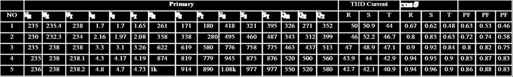
58 Open circuit In this experiment the secondary is in open circuit and the primary is under normal voltage. In this experiment it is clear that the power consumed by the primary is used in the magnetization and as losses in the core of the transformer. The next parameter must be measured in this experiment. V OC, I OC and P OC The next table summarizes the result of this experiment Primary: Table 5.1: open circuit parameters (Primary) U R 241.5V I R 1.48A S 1 358VA P 1 131W U S V I S 1.02A S 2 249VA P 2 45W U T V I T 1.538A S 3 374VA P 3 5W Secondary Table 5.2: open circuit parameters (Secondary) U SA U SB U SA 27.61V 27.22V 27.15V We can notice that the current in the primary phases are aboutly equals in the secondary there is no current which the secondary voltage are: 2 2 P OC = R P I OC + R C I OC P OC = R P I OC + R IR 5.2 P OC R IR 5.3 P OC = V OC I OC cos OC = R IR 5.4
59 46 2 P OC = V OC I OC = R C I OC 5.5 R C = V OC I OC = V 2 OC 5.6 R IR V RC = V XM 5.7 R C = I OC cos OC = X M I OC sin OC 5.8 R IR power for losses I OC Active current X M = R C I OC cos OC I OC sin OC 5.9 cos OC = P OC V OC I OC = W AV 5.10 S OC = V OC I OC R C = V 2 OC X P M = OC 2 2 Q OC = S OC P OC 2 V OC Q OC Using the next formulas we can calculate the core losses and magnetization parameters as follow. Phase R: R C = V OC I OC = OR I OC P S = = 28939Ω R C = V 2 OC = P OC = 28939Ω X M = 2 V OC = Q OC S 2 OC P2 OC = Ω
60 47 Phase S: R C = V OC I OC = OR I OC P S = = 1715Ω R C = V 2 OC = P OC = 1715Ω X M = 2 V OC = Q OC S 2 OC P2 OC = 240Ω Phase T: R C = V OC I OC = OR I OC P S = = 410.3Ω R C = V 2 OC = P OC = 410.3Ω X M = 2 V OC = Q OC S 2 OC P2 OC = 168Ω
61 Short circuit experiment In this experiment the secondary phases of the transformer are short circuit and the primary voltage is reduced. From this experiment the equivalent resistor and inductors of the primary and secondary can be determined as shown in the next figure. Figure 5.4: Connection for transformer short circuit test The result of this experiment is shown in the next table: Primary: Tables 5.3: short circuit parameters (Primary) U R 21.41V I R 9.18A S VA P W U S V I S 10.27A S 2 216VA P 2 203W U T 21.17V I T 10.17A S VA P W cos 1 cos 2 cos
62 Secondary Current: I = 82 A. We can see that the primary voltage was 21V because we reduced it in order to avoid the passage of high current in the transformer. The next formulas explained the steps to calculatex 1, X 2, R 1 and R 2 2 P J = R P I PSC 2 + R S I SSC 5.11 P PSC = V PSC I PSC cos PSC P PSC = R P I PSC 2 P PSC = R S I SSC 2 + R S I SSC R S = P PSC I SSC Q PSC = V PSC I PSC sin PSC Q PSC = L fp ω I PSC 2 + L fs ω I SSC 5.17 X S = Q PSC I2 X S = SSC mv PSC I SSC 2 RS 5.18 m = N P N S = V P V S = I S I P 5.19 ω= 2πf 5.20 Z SC = V SC P PF = cos I OC = OC Q = cos 1 P OC SC V OC I OC V OC I OC Z SC = V SC I SC R SC = Z SC cos SC P R SC SC = I2 X S = Z 2 2 SC R SC SC X S = Z SC sin SC
63 50 After the calculation of the parameters we found these results: Phase R : a= = 8.82 R R = P I 2 = = 2.21Ω Z R = V I = 2.33Ω X R = Z R 2 R R 2 = 0.73Ω R R = R 1 + a 2 R 2 X R = X 1 + a 2 X 2 R 1 = a 2 R 2 = 0.5R R R 2 = 1 2 R R a 2 = = 0.014Ω R 1 = a 2 R 2 = * = 1.089Ω X 1 = a 2 X 2 = 0.5X R X 2 = 1 2 X R a 2 = =4.69*10 3 Ω X 1 = a 2 X 2 = *4.69*10 3 = 0.36Ω Phase S : a= = 8.82 R S = P I 2 = = 1.92Ω
64 51 Z S = V I = 2.05Ω X S = Z S 2 R S 2 = 0.718Ω R S = R 1 + a 2 R 2 X S = X 1 + a 2 X 2 R 1 = a 2 R 2 = 0.5R S R 2 = 1 2 R S a 2 = = Ω R 1 = a 2 R 2 = * = 0.96Ω X 1 = a 2 X 2 = 0.5X S X 2 = 1 2 X S a 2 = =4.61*10 3 Ω X 1 = a 2 X 2 = *4.61*10 3 = 0.359Ω Phase T : a= = 8.82 R T = P I 2 = = 1.99Ω Z T = V I = 2.08Ω X T = Z T 2 R T 2 = 0.605Ω R T = R 1 + a 2 R 2
65 52 X T = X 1 + a 2 X 2 R 1 = a 2 R 2 = 0.5R T R 2 = 1 2 R T a 2 = = Ω R 1 = a 2 R 2 = * =0.995 Ω X 1 = a 2 X 2 = 0.5X S X 2 = 1 2 X S a 2 = =3.888*10 3 Ω X 1 = a 2 X 2 = *3.888*10 3 = Ω
66 Transformer Data Tables 5.4: Transformer Data Parameter Value R S T R P Ω X P Ω R S Ω X S Ω 4.69* * *10 3 R C Ω X M Ω S (VA) 8K V P (V) 415 V S (V) 47 A 8.82
67 Experiments Linear Load Condition Firstly we connected resistive linear load with the transformer as shown in fig 5.5 and used the digital signal analyzer to Secord and measure the current, voltage, power, power factor and distortion factor of the voltage and current of the transformer. The value of resistive load was gradually decreased and the same measurements were taken to verify the obtained results and to examine the transformer losses under different resistive load in order to verify the accuracy of the obtained results. a Power quality Analyzer b c Transformer Figure 5.5: Linear Load Condition Fig5.6 shows the voltage and current wave forms with the harmonic spectrum of load current. As seen in fig 5.6 the load current is purely sinusoidal and in phase with the voltage. Table 5.5 shows the obtained results in the case of resistive liner load.


68 55 Figure 5.6: Linear load V, I waveforms and harmonic Is clear from table 5.5 that power factor in the secondary of the transformer is one and the reactive power consumption.
69 56 These are no reactive power consumption. After the calculation of power losses in the transformer by subtracting the output power from the input power for each phase we can and compare these power losses with the transformer losses determined earlier. P loss = P in P out 5.21 We can notice that the losses in the case of resistive liner load as about the same as in open circuit experiment which means that the linear resistive load doesn t cause any extra losses for the transformer. As it is clear from the transformer efficiency results we can see that the efficiency of the transformer was 26% in the case of low power consumption and reached the value of 89% at about 50% of the rating of transformer. The efficiency is due to the fact that consumed power was small if compared with the power nailed for the magnetization of the transformer core and the iron losses. The THD of load current was less than 3% in this experiment.


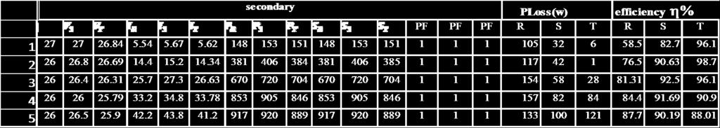
70 Tables 5.5: Linear Load Condition 57
71 Experiments Nonlinear inductive load Condition In this case a nonlinear load was connected to the transformer in order to verify the effect of nonlinear loads on the harmonic spectrum of current and voltage and the effect of harmonic current on the transformer efficiency and losses the nonlinear. In the case shown in fig 5.7 it is composed of three phase diode rectifier with RL load. The load was increased gradually. Figure 5.7: Nonlinear inductive load Condition The results of this experiment are tabulated in table 5.6 the THD value of the load currents is between 24 and These values of THD are due to the use of nonlinear loads which injects harmonic currents into the source side. The power factor was decreased from one to about 95% in this case due to existence of inductive load which consume reactive power. Fig 5.8 shows the wave forms of current and voltage with the harmonic spectrum of the current.

: Figure 5.")
72 59 Figure 5.8: Nonlinear load V, I waveforms and harmonic Nonlinear load, current harmonic (primary): Figure 5.9: Nonlinear load, current harmonic (primary)
 + n= I a 2 n=2 lh 2 (R S + R P ) 5.23 a 2 The efficiency of the transformer was 92.")
73 60 Nonlinear load, current harmonic (secondary): Figure 5.10: Nonlinear load, current harmonic (secondary) The losses in the transformer were increased due to existence of harmonics. The loses of transformer in the case of harmonics are given below P loss = P NL P FL 5.22 P cu = I 2 l (R S + R P ) + n= I a 2 n=2 lh 2 (R S + R P ) 5.23 a 2 The efficiency of the transformer was 92.5% at 39% of the transformer power.


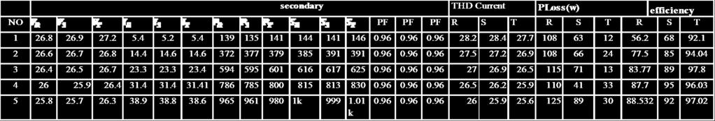
74 Tables 5.6: Inductive Nonlinear Load Condition 61
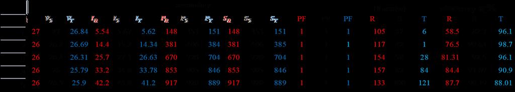
75 Experiments Nonlinear Capacitive Loads Condition In this case a capacitive load was connected to recitatives as shown in figure 5.11 the results measured and tabulated in table 5.7 Figure 5.11: Nonlinear Capacitive load These values of THD are due to the use of nonlinear loads which injects harmonic currents into the source side. The power factor was decreased from one to about 95% in this case due to existence of inductive load which consume reactive power. Fig 5.12 shows the wave forms of current and voltage with the harmonic spectrum of the current. The losses in the transformer were increased due to existence of harmonics. The loses of transformer in the case of harmonics are given below P loss = P NL P FL 5.24 P cu = I 2 l (R S + R P ) + n= I a 2 n=2 lh 2 (R S + R P ) 5.25 a 2 From the above equation, it can be concluded that the copper losses are related to the harmonics order. In the following section, linear and nonlinear load measurement tests were done over transformer The efficiency of the transformer was 92% at 37% of the transformer power.


76 63 In figure 5.10 we can see that the slope of the current wave from is totally distorted and the THD of current wave forms arrive the value of 79% Figure 5.12: Nonlinear load V, I waveforms and harmonic Nonlinear load, current harmonic (primary): Figure 5.13: Nonlinear load, current harmonic (primary)
 From the table of results we can see that the capacitive non linear loads")
77 64 Nonlinear load, current harmonic (secondary): Figure 5.14: Nonlinear load, current harmonic (secondary) From the table of results we can see that the capacitive non linear loads increasing the THD transformer current the value of THD arrive the value of 79%.

78 Tables 5.7: Capacitive Nonlinear Load Condition 65
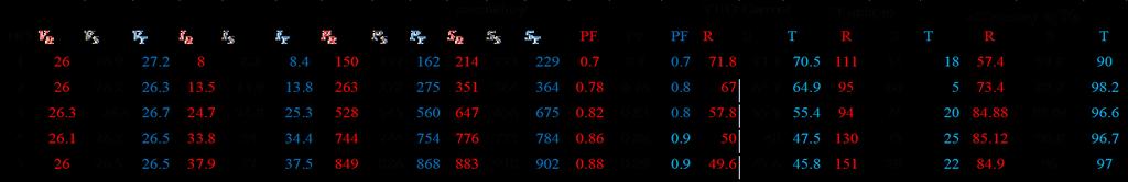
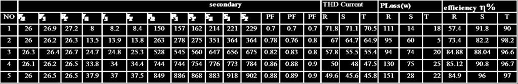
79 Transformer losses and efficiency (Practical) Tables 5.8: Transformer losses and efficiency (Practical) Linear Load Inductive Nonlinear Load Capacitive Nonlinear Load NO I P loss efficiency I P loss efficiency I P loss Efficiency mean Transformer losses and efficiency (Theoretical) Tables 5.9: Transformer losses and efficiency (Theoretical) Linear Load Inductive Nonlinear Load Capacitive Nonlinear Load NO I P loss efficiency(%) I P loss efficiency(%) I P loss efficiency(%) mean Error between the theoretical and practical values Tables 5.10: Error between the theoretical and practical values Linear Load error Inductive Nonlinear Load error Capacitive Nonlinear Load error NO I P loss Efficiency(%) I P loss Efficiency(%) I P loss efficiency(%) mean
80 Linear and nonlinear load Condition, current harmonic Tables 5.11: Linear and nonlinear load Condition, current harmonic Linear Load Condition Nonlinear inductive load Condition Nonlinear Capacitive load Condition Harmoni c Order I h /I 1 Harmonic Order I h /I 1 Difference % Harmonic Order I h /I 1 Difference % A A A A A A A A A A A A A A A A Transformer losses and efficiency using MATLAB The transformer and non linear load models were designed using MATLAB/SIMULINK with the real transformer and load parameters. All the results were obtained from the model and tabulated in table (5.11). Tables 5.12: Linear Load Condition using MATLAB R I THD Tables 5.13: Inductive Nonlinear Load Condition using MATLAB R I THD
81 68 Tables 5.14: Capacitive Nonlinear Load Condition using MATLAB R I THD Tables 5.15: Transformer losses and efficiency using MATLAB Linear Load Inductive Nonlinear Load Capacitive Nonlinear Load NO I P loss efficiency I P loss efficiency I P loss Efficiency mean
82 MATLAB/SIMULINK Figure 5.15: MATLAB/SIMULINK
83 70 Different elements of the program: 1-Three phase AC voltage source: The AC Voltage Source block implements an ideal AC voltage source 2-Three phase VI measurement: Used to measure three-phase voltages and currents in a circuit. When connected in series with three-phase elements, it returns the three phase-to-ground or phase-to-phase voltages and the three line currents. 3-Three-phase linear transformer: Implements three single-phase, two-winding linear transformers where all the twelve winding connectors are accessible. The block can be used in place of the Three-Phase Transformer (Two Windings) block to implement a three-phase transformer when primary and secondary are not necessarily connected in Y or Delta. 4-grid impedance: Three phase RL elements used to represent the internal resistance and inductance of cables or transformers in grid. 5- Diode: The diode is a semiconductor device that is controlled by its own voltage V ak and current I ak. When a diode is forward biased (V ak > 0), it starts to conduct with a small forward voltage V f across it. It turns off when the current flow into the device becomes 0. When the diode is reverse biased (V ak < 0), it stays in the off state. A + - K anode cathode 6- Resistance: dc load 7- Inductor: Resistance in series with inductor in rectifier 8- Capacitor: in parallel with the load to smooth output voltage
84 71 9- The Voltage Measurement block: measures the instantaneous voltage between two electric nodes. In this program it is used to measure the output voltage of the diode rectifier. 10- The Scope block displays its input with respect to simulation time: The Scope block can have multiple axes (one per port) and all axes have a common time range with independent y- axes. The Scope block allows you to adjust the amount of time and the range of input values displayed. You can move and resize the Scope window and you can modify the Scope's parameter values during the simulation. 11- THD calculation block: this block is used to calculate the Fourier Transform of a signal and the total harmonic distortion, its output is the THD. 12- Three phase active and reactive power it is used to calculate the active and reactive power when provided with three phase voltage and current. 13- RMS value calculation block: used to calculate the RMS value of a given signal. In the program it is used to determine the RMS value of the load current. 14- Bridge rectifier: implements 6 diodes to construct a three phase bridge rectifier which is used to convert the AC electric power and current to DC power

 Figure 5.")

85 Linear Load Condition using MATLAB Figure 5.16: linear load current (secondary) Figure 5.17: linear load voltage (secondary) Figure 5.18: linear load harmonic (secondary)

 Figure 5.")

86 Nonlinear inductive load Condition using MATLAB Figure 5.19: Nonlinear load voltage for inductor (secondary) Figure 5.20: Nonlinear load current for inductor (secondary) Figure 5.21: Nonlinear load harmonic for inductor (secondary)

 Figure 5.")

87 Nonlinear Capacitive Loads Condition using MATLAB Figure 5.22: Nonlinear load voltage for capacitor (primary) Figure 5.23: Nonlinear load current for capacitor (primary) Figure 5.24: Nonlinear load harmonic for capacitor (primary)


")
88 75 Figure 5.25: Nonlinear load current for capacitor (primary) Figure 5.26: Nonlinear load voltage for capacitor (primary) Figure 5.27: Nonlinear load harmonic for capacitor (secondary)
89 76 The theoretical losses in this experiment were calculated and it has been found that the error was not too much but there is still a small error due to the existence of some factors that were not taken in consideration. We can notice also that the error in the cause of non linear load was more important due to the harmonics. From the tables we can notice that there is difference between the theoretical values for the power, the efficiency, and the losses of the transformer. We have taken many reading for the linear and non linear loads cases with the transformer. The theoretical calculations have been done dependent on the theory explained in chapter II and compared with the practical values. The comparison has been done for similar current values for the three load types (linear, inductive non linear and capacitive non linear). The efficiency error between the theoretical and practical results was calculated and tabulated in table (3). From this table we can notice that the efficiency error is bigger in the case of the non linear load than in the linear load. That is due to the existent of current harmonic with different levels in the case of the non linear loads. These harmonics cause extra power losses in the core of the transformer and in the primary and secondary circuits. These losses are difficult to be taken in consideration in the theoretical calculations. In the linear load case we can notice that the error between the theory and the experimental results is small and that error can be explained by many sources of error such as the errors in the measurement devices, the errors in the identification of the transformer parameters which is due to the changing conditions of the experiment; such as the grid voltage which can be affected by the number of users connected to the grid at the moment of conducting the experiment. The transformer conditions such as temperature can also affect the results of the experiment. The model of the transformer and the linear and non linear load were built in MATLAB simulation environment. The results were printed and it showed that the increase of harmonics causes an increase in the transformer losses. The results obtained in MATLAB shows better performance than those in experiment due to the fact that MATLAB deals with mathematic formulas without considering the environment in which the experiment has been conducted.

90 Figure 4.28: Three Phase Bridge Rectifier 77
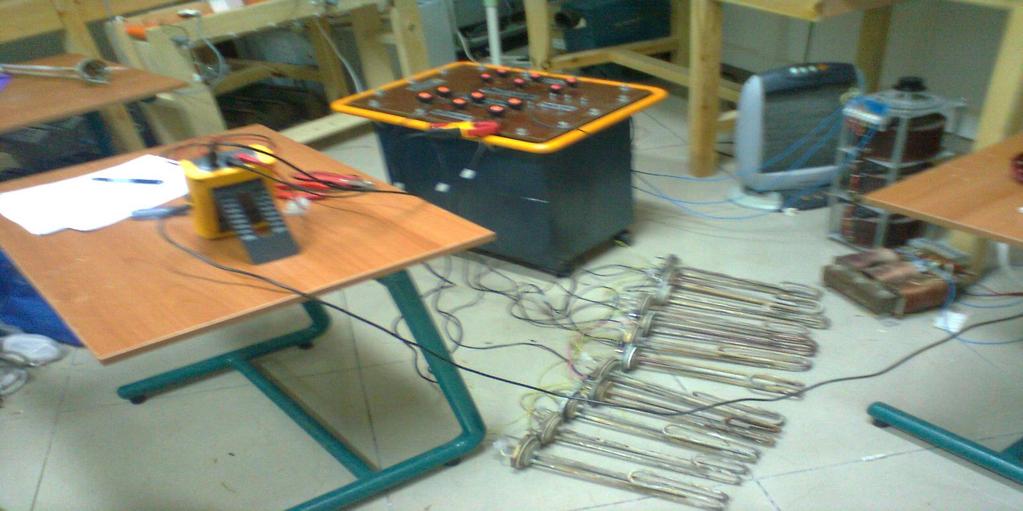
91 78
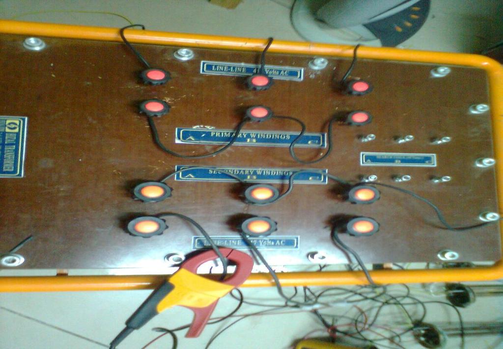
92 79


93 Figures 4.29: Arrangement of Experimental Set-up (three phases) 80
UNIVERSITY OF TECHNOLOGY By: Fadhil A. Hasan ELECTRICAL MACHINES
 UNIVERSITY OF TECHNOLOGY DEPARTMENT OF ELECTRICAL ENGINEERING Year: Second 2016-2017 By: Fadhil A. Hasan ELECTRICAL MACHINES І Module-II: AC Transformers o Single phase transformers o Three-phase transformers
Transformers. gpmacademics.weebly.com
 TRANSFORMERS Syllabus: Principles of operation, Constructional Details, Losses and efficiency, Regulation of Transformer, Testing: OC & SC test. TRANSFORMER: It is a static device which transfers electric
ISSN: X Impact factor: (Volume 3, Issue 6) Available online at Modeling and Analysis of Transformer
 Available online at Modeling and Analysis of Transformer") ISSN: 2454-132X Impact factor: 4.295 (Volume 3, Issue 6) Available online at www.ijariit.com Modeling and Analysis of Transformer Divyapradeepa.T Department of Electrical and Electronics, Rajalakshmi Engineering
ISSN: 2454-132X Impact factor: 4.295 (Volume 3, Issue 6) Available online at www.ijariit.com Modeling and Analysis of Transformer Divyapradeepa.T Department of Electrical and Electronics, Rajalakshmi Engineering
Unit 3 Magnetism...21 Introduction The Natural Magnet Magnetic Polarities Magnetic Compass...21
 Chapter 1 Electrical Fundamentals Unit 1 Matter...3 Introduction...3 1.1 Matter...3 1.2 Atomic Theory...3 1.3 Law of Electrical Charges...4 1.4 Law of Atomic Charges...4 Negative Atomic Charge...4 Positive
Preface...x Chapter 1 Electrical Fundamentals
 Preface...x Chapter 1 Electrical Fundamentals Unit 1 Matter...3 Introduction...3 1.1 Matter...3 1.2 Atomic Theory...3 1.3 Law of Electrical Charges...4 1.4 Law of Atomic Charges...5 Negative Atomic Charge...5
CHAPTER 4. Distribution Transformers
 CHAPTER 4 Distribution Transformers Introduction A transformer is an electrical device that transfers energy from one circuit to another purely by magnetic coupling. Relative motion of the parts of the
CHAPTER 2. Transformers. Dr Gamal Sowilam
 CHAPTER Transformers Dr Gamal Sowilam Introduction A transformer is a static machine. It is not an energy conversion device, it is indispensable in many energy conversion systems. A transformer essentially
KNOW MORE ABOUT THE TRANSFORMERS. Glossary Transformers
 KNOW MORE ABOUT THE TRANSFORMERS Glossary Transformers Ambient temperature The existing temperature of the atmosphere surrounding a transformer installation. Ampere The practical unit of electric current.
Walchand Institute of Technology. Basic Electrical and Electronics Engineering. Transformer
 Walchand Institute of Technology Basic Electrical and Electronics Engineering Transformer 1. What is transformer? explain working principle of transformer. Electrical power transformer is a static device
Generator Advanced Concepts
 Generator Advanced Concepts Common Topics, The Practical Side Machine Output Voltage Equation Pitch Harmonics Circulating Currents when Paralleling Reactances and Time Constants Three Generator Curves
FGJTCFWP"KPUVKVWVG"QH"VGEJPQNQI[" FGRCTVOGPV"QH"GNGEVTKECN"GPIKPGGTKPI" VGG"246"JKIJ"XQNVCIG"GPIKPGGTKPI
 FGJTFWP"KPUKWG"QH"GEJPQNQI[" FGRTOGP"QH"GNGETKEN"GPIKPGGTKPI" GG"46"JKIJ"XQNIG"GPIKPGGTKPI Resonant Transformers: The fig. (b) shows the equivalent circuit of a high voltage testing transformer (shown
Effects of Harmonic Distortion I
 Effects of Harmonic Distortion I Harmonic currents produced by nonlinear loads are injected back into the supply systems. These currents can interact adversely with a wide range of power system equipment,
Module 1. Introduction. Version 2 EE IIT, Kharagpur
 Module 1 Introduction Lesson 1 Introducing the Course on Basic Electrical Contents 1 Introducing the course (Lesson-1) 4 Introduction... 4 Module-1 Introduction... 4 Module-2 D.C. circuits.. 4 Module-3
(2) New Standard IEEE P (3) Core : (4) Windings :
 New Standard IEEE P (3) Core : (4) Windings :") (d) Electrical characteristics (such as short-circuit withstand, commutating reactance, more number of windings, etc); (e) Longer life expectancy; (f) Energy efficiency; (g) more demanding environment.
(d) Electrical characteristics (such as short-circuit withstand, commutating reactance, more number of windings, etc); (e) Longer life expectancy; (f) Energy efficiency; (g) more demanding environment.
1. Introduction to Power Quality
 1.1. Define the term Quality A Standard IEEE1100 defines power quality (PQ) as the concept of powering and grounding sensitive electronic equipment in a manner suitable for the equipment. A simpler and
Transformer Winding Design. The Design and Performance of Circular Disc, Helical and Layer Windings for Power Transformer Applications
 The Design and Performance of Circular Disc, Helical and Layer Windings for Power Transformer Applications Minnesota Power Systems Conference November 3 5, 2009 Earl Brown Heritage Center University of
HIGH VOLTAGE ENGINEERING(FEEE6402) LECTURER-24
 LECTURER-24") LECTURER-24 GENERATION OF HIGH ALTERNATING VOLTAGES When test voltage requirements are less than about 300kV, a single transformer can be used for test purposes. The impedance of the transformer should
LECTURER-24 GENERATION OF HIGH ALTERNATING VOLTAGES When test voltage requirements are less than about 300kV, a single transformer can be used for test purposes. The impedance of the transformer should
Electrical Theory. Power Principles and Phase Angle. PJM State & Member Training Dept. PJM /22/2018
 Electrical Theory Power Principles and Phase Angle PJM State & Member Training Dept. PJM 2018 Objectives At the end of this presentation the learner will be able to: Identify the characteristics of Sine
Failure of Transformers Due to Harmonic Loads
 Failure of Transformers Due to Harmonic Loads 1 Jyotirmaya Ghadai, 2 Chinmay Das 1,2 Department of Electrical Engineering, Indira Gandhi Institute of Technology Email: 1 jyotighadai05@gmail.com, 2 Chinmaydas14@gmail.com
WELCOME TO THE LECTURE
 WLCOM TO TH LCTUR ON TRNFORMR Single Phase Transformer Three Phase Transformer Transformer transformer is a stationary electric machine which transfers electrical energy (power) from one voltage level
3. What is hysteresis loss? Also mention a method to minimize the loss. (N-11, N-12)
") DHANALAKSHMI COLLEGE OF ENGINEERING, CHENNAI DEPARTMENT OF ELECTRICAL AND ELECTRONICS ENGINEERING EE 6401 ELECTRICAL MACHINES I UNIT I : MAGNETIC CIRCUITS AND MAGNETIC MATERIALS Part A (2 Marks) 1. List
DHANALAKSHMI COLLEGE OF ENGINEERING, CHENNAI DEPARTMENT OF ELECTRICAL AND ELECTRONICS ENGINEERING EE 6401 ELECTRICAL MACHINES I UNIT I : MAGNETIC CIRCUITS AND MAGNETIC MATERIALS Part A (2 Marks) 1. List
EE 340 Power Transformers
 EE 340 Power Transformers Preliminary considerations A transformer is a device that converts one AC voltage to another AC voltage at the same frequency. It consists of one or more coil(s) of wire wrapped
SECTION 4 TRANSFORMERS. Yilu (Ellen) Liu. Associate Professor Electrical Engineering Department Virginia Tech University
 Liu. Associate Professor Electrical Engineering Department Virginia Tech University") SECTION 4 TRANSFORMERS Yilu (Ellen) Liu Associate Professor Electrical Engineering Department Virginia Tech University Analysis of Transformer Turns Ratio......................... 4.2 Analysis of a Step-Up
SECTION 4 TRANSFORMERS Yilu (Ellen) Liu Associate Professor Electrical Engineering Department Virginia Tech University Analysis of Transformer Turns Ratio......................... 4.2 Analysis of a Step-Up
EEE3441 Electrical Machines Department of Electrical Engineering. Lecture. Basic Operating Principles of Transformers
 Department of Electrical Engineering Lecture Basic Operating Principles of Transformers In this Lecture Basic operating principles of following transformers are introduced Single-phase Transformers Three-phase
CHAPTER 2. Basic Concepts, Three-Phase Review, and Per Unit
 CHAPTER 2 Basic Concepts, Three-Phase Review, and Per Unit 1 AC power versus DC power DC system: - Power delivered to the load does not fluctuate. - If the transmission line is long power is lost in the
TRANSFORMERS PART A. 2. What is the turns ratio and transformer ratio of transformer? Turns ratio = N2/ N1 Transformer = E2/E1 = I1/ I2 =K
 UNIT II TRANSFORMERS PART A 1. Define a transformer? A transformer is a static device which changes the alternating voltage from one level to another. 2. What is the turns ratio and transformer ratio of
Emicon Engineering Consultants L.L.C.
 Emicon Engineering Consultants L.L.C. Power Quality Consulting & Solutions Presentation / Pre-Qualification Emicon, Specialised in Power Quality Consulting and Pollution Control on Electrical Network www.emiconconsultants.com
148 Electric Machines
 148 Electric Machines 3.1 The emf per turn for a single-phase 2200/220- V, 50-Hz transformer is approximately 12 V. Calculate (a) the number of primary and secondary turns, and (b) the net cross-sectional
ELECTRICAL POWER ENGINEERING
 Introduction This trainer has been designed to provide students with a fully comprehensive knowledge in Electrical Power Engineering systems. The trainer is composed of a set of modules for the simulation
DESIGN AND CONSTRUCTION OF 1500VA VARIABLE OUTPUT STEP DOWN TRANSFORMER
 DESIGN AND CONSTRUCTION OF 1500VA VARIABLE OUTPUT STEP DOWN TRANSFORMER OGUNDARE AYOADE B., OMOGOYE O. SAMUEL & OLUWASANYA OMOTAYO J. Department of Electrical/Electronic engineering, Lagos State Polytechnic,
Voltage and Current Waveforms Enhancement using Harmonic Filters
 Voltage and Current Waveforms Enhancement using Harmonic Filters Rajeb Ibsaim rabsaim@yahoo.com, Azzawia University, Libya Amer Daeri ibnjubair1@yahoo.co.uk Azzawia University, Libya Abstract The demand
Power. Power is the rate of using energy in joules per second 1 joule per second Is 1 Watt
 3 phase Power All we need electricity for is as a source of transport for energy. We can connect to a battery, which is a source of stored energy. Or we can plug into and electric socket at home or in
ELECTROMAGNETIC INDUCTION AND ALTERNATING CURRENT (Assignment)
") ELECTROMAGNETIC INDUCTION AND ALTERNATING CURRENT (Assignment) 1. In an A.C. circuit A ; the current leads the voltage by 30 0 and in circuit B, the current lags behind the voltage by 30 0. What is the
ELECTROMAGNETIC INDUCTION AND ALTERNATING CURRENT (Assignment) 1. In an A.C. circuit A ; the current leads the voltage by 30 0 and in circuit B, the current lags behind the voltage by 30 0. What is the
86 chapter 2 Transformers
 86 chapter 2 Transformers Wb 1.2x10 3 0 1/60 2/60 3/60 4/60 5/60 6/60 t (sec) 1.2x10 3 FIGURE P2.2 2.3 A single-phase transformer has 800 turns on the primary winding and 400 turns on the secondary winding.
1. (a) Determine the value of Resistance R and current in each branch when the total current taken by the curcuit in figure 1a is 6 Amps.
 Determine the value of Resistance R and current in each branch when the total current taken by the curcuit in figure 1a is 6 Amps.") Code No: 07A3EC01 Set No. 1 II B.Tech I Semester Regular Examinations, November 2008 ELECTRICAL AND ELECTRONICS ENGINEERING ( Common to Civil Engineering, Mechanical Engineering, Mechatronics, Production
Code No: 07A3EC01 Set No. 1 II B.Tech I Semester Regular Examinations, November 2008 ELECTRICAL AND ELECTRONICS ENGINEERING ( Common to Civil Engineering, Mechanical Engineering, Mechatronics, Production
El-Hawary, M.E. The Transformer Electrical Energy Systems. Series Ed. Leo Grigsby Boca Raton: CRC Press LLC, 2000
 El-Hawary, M.E. The Transformer Electrical Energy Systems. Series Ed. Leo Grigsby Boca Raton: CRC Press LLC, 000 97 Chapter 4 THE TRANSFORMER 4. NTRODUCTON The transformer is a valuable apparatus in electrical
CHAPTER 4 HARMONICS AND POWER FACTOR
 4.1 Harmonics CHAPTER 4 HARMONICS AND POWER FACTOR In this research a comparative study of practical aspects of mixed use of diode and Thyristor converter technologies in Aluminium Smelters has been carried
R. W. Erickson. Department of Electrical, Computer, and Energy Engineering University of Colorado, Boulder
 R. W. Erickson Department of Electrical, Computer, and Energy Engineering University of Colorado, Boulder 16.4. Power phasors in sinusoidal systems Apparent power is the product of the rms voltage and
MAHARASHTRA STATE BOARD OF TECHNICAL EDUCATION
 Important Instructions to examiners: 1) The answers should be examined by key words and not as word-to-word as given in the model answer scheme. 2) The model answer and the answer written by candidate
Fundamentals of Power Electronics
 Fundamentals of Power Electronics SECOND EDITION Robert W. Erickson Dragan Maksimovic University of Colorado Boulder, Colorado Preface 1 Introduction 1 1.1 Introduction to Power Processing 1 1.2 Several
Three Winding Transformer.
 Three Winding Transformer. By G. K. KAISER (Transformer Engineer, Mitsubishi Denki-Kabushikikaisha.) Abstract. Three winding transformers afford many advantages on large power systems and their use has
Manuals. Basic Electrical Engineering BE-104
 Manuals Basic Electrical Engineering BE-104 S.NO. EXPERIMENT NAME DATE 1 Measurement of power & power factor in a single phase AC circuit using three Ammeter Method 2 Measurement of active & reactive power
ELECTRICAL POWER TRANSMISSION TRAINER
 ELECTRICAL POWER TRANSMISSION TRAINER ELECTRICAL POWER TRANSMISSION TRAINER This training system has been designed to provide the students with a fully comprehensive knowledge in Electrical Power Engineering
Electrical Machines I : Transformers
 UNIT TRANSFORMERS PART A (Q&A) 1. What is step down transformer? The transformer used to step down the voltage from primary to secondary is called as step down transformer. (Ex: /11).. Draw the noload
QUESTION BANK ETE (17331) CM/IF. Chapter1: DC Circuits
 CM/IF. Chapter1: DC Circuits") QUESTION BANK ETE (17331) CM/IF Chapter1: DC Circuits Q1. State & explain Ohms law. Also explain concept of series & parallel circuit with the help of diagram. 3M Q2. Find the value of resistor in fig.
QUESTION BANK ETE (17331) CM/IF Chapter1: DC Circuits Q1. State & explain Ohms law. Also explain concept of series & parallel circuit with the help of diagram. 3M Q2. Find the value of resistor in fig.
SYNCHRONOUS MACHINES
 SYNCHRONOUS MACHINES The geometry of a synchronous machine is quite similar to that of the induction machine. The stator core and windings of a three-phase synchronous machine are practically identical
Harmonic Requirements
 Chapter 1 Harmonic Requirements 1.1 INTRODUCTION Placing limits upon the effects that nonlinear loads may produce on users of electric power requires definition of system and equipment parameters. The
Basic Principles and Operation of Transformer
 Basic Principles and Operation of Transformer CONSTRUCTIONAL ASPECTS Cores In order to enhance core s magnetic properties, it is constructed from an iron and silicon mixture (alloy). The magnetic core
Lecture 36 Measurements of High Voltages (cont) (Refer Slide Time: 00:14)
 (Refer Slide Time: 00:14)") Advances in UHV Transmission and Distribution Prof. B Subba Reddy Department of High Voltage Engg (Electrical Engineering) Indian Institute of Science, Bangalore Lecture 36 Measurements of High Voltages
Advances in UHV Transmission and Distribution Prof. B Subba Reddy Department of High Voltage Engg (Electrical Engineering) Indian Institute of Science, Bangalore Lecture 36 Measurements of High Voltages
VALLIAMMAI ENGINEERING COLLEGE
 VALLIAMMAI ENGINEERING COLLEGE SRM Nagar, Kattankulathur 603 203 DEPARTMENT OF ELECTRONICS AND INSTRUMENTATION ENGINEERING QUESTION BANK IV SEMESTER EI6402 ELECTRICAL MACHINES Regulation 2013 Academic
TO LIMIT degradation in power quality caused by nonlinear
 1152 IEEE TRANSACTIONS ON POWER ELECTRONICS, VOL. 13, NO. 6, NOVEMBER 1998 Optimal Current Programming in Three-Phase High-Power-Factor Rectifier Based on Two Boost Converters Predrag Pejović, Member,
Resonant Power Conversion
 Resonant Power Conversion Prof. Bob Erickson Colorado Power Electronics Center Department of Electrical, Computer, and Energy Engineering University of Colorado, Boulder Outline. Introduction to resonant
The power transformer
 ELEC0014 - Introduction to power and energy systems The power transformer Thierry Van Cutsem t.vancutsem@ulg.ac.be www.montefiore.ulg.ac.be/~vct November 2017 1 / 35 Power transformers are used: to transmit
CHAPTER 5 POWER QUALITY IMPROVEMENT BY USING POWER ACTIVE FILTERS
 86 CHAPTER 5 POWER QUALITY IMPROVEMENT BY USING POWER ACTIVE FILTERS 5.1 POWER QUALITY IMPROVEMENT This chapter deals with the harmonic elimination in Power System by adopting various methods. Due to the
Experiment No. Experiments for First Year Electrical Engg Lab
 Experiment No im: To determine Regulation and Efficiency of a single phase transformer using open circuit (O.C.) and short circuit (S.C.) tests pparatus: - Single phase transformer Single phase dimmer
22.0 Harmonics in Industrial Power Systems
 1.0 Harmonics in Industrial Power Systems Harmonic frequencies are multiples of the line (fundamental) frequency, which in North America is usually 60 Hz, while it is 50 Hz elsewhere. Figure 1 shows a
2 Grounding of power supply system neutral
 2 Grounding of power supply system neutral 2.1 Introduction As we had seen in the previous chapter, grounding of supply system neutral fulfills two important functions. 1. It provides a reference for the
CONTENTS. 1. Introduction Generating Stations 9 40
 CONTENTS 1. Introduction 1 8 Importance of Electrical Energy Generation of Electrical Energy Sources of Energy Comparison of Energy Sources Units of Energy Relationship among Energy Units Efficiency Calorific
Chapter -3 ANALYSIS OF HVDC SYSTEM MODEL. Basically the HVDC transmission consists in the basic case of two
 Chapter -3 ANALYSIS OF HVDC SYSTEM MODEL Basically the HVDC transmission consists in the basic case of two convertor stations which are connected to each other by a transmission link consisting of an overhead
A Practical Guide to Free Energy Devices
 A Practical Guide to Free Energy Devices Part PatD14: Last updated: 25th February 2006 Author: Patrick J. Kelly This patent application shows the details of a device which it is claimed, can produce sufficient
By Gill ( ) PDF created with FinePrint pdffactory trial version
 PDF created with FinePrint pdffactory trial version") By Gill (www.angelfire.com/al4/gill ) 1 Introduction One of the main reasons of adopting a.c. system instead of d.c. for generation, transmission and distribution of electrical power is that alternatin
By Gill (www.angelfire.com/al4/gill ) 1 Introduction One of the main reasons of adopting a.c. system instead of d.c. for generation, transmission and distribution of electrical power is that alternatin
MAHARASHTRA STATE BOARD OF TECHNICAL EDUCATION
 Important Instructions to examiners: 1) The answers should be examined by key words and not as word-to-word as given in the model answer scheme. 2) The model answer and the answer written by candidate
TRANSFORMERS INTRODUCTION
 Tyco Electronics Corporation Crompton Instruments 1610 Cobb International Parkway, Unit #4 Kennesaw, GA 30152 Tel. 770-425-8903 Fax. 770-423-7194 TRANSFORMERS INTRODUCTION A transformer is a device that
AC Power Instructor Notes
 Chapter 7: AC Power Instructor Notes Chapter 7 surveys important aspects of electric power. Coverage of Chapter 7 can take place immediately following Chapter 4, or as part of a later course on energy
Chapter 33. Alternating Current Circuits
 Chapter 33 Alternating Current Circuits C HAP T E O UTLI N E 33 1 AC Sources 33 2 esistors in an AC Circuit 33 3 Inductors in an AC Circuit 33 4 Capacitors in an AC Circuit 33 5 The L Series Circuit 33
~=E.i!=h. Pre-certification Transformers
 7 Transformers Section 26 of the electrical code governs the use and installations of transformers. A transformer is a static device used to transfer energy from one alternating current circuit to another.
High Voltage DC Transmission Prof. Dr. S. N. Singh Department of Electrical Engineering Indian Institute of Technology, Kanpur
 High Voltage DC Transmission Prof. Dr. S. N. Singh Department of Electrical Engineering Indian Institute of Technology, Kanpur Module No. # 01 Lecture No. # 02 Comparison of HVAC and HVDC Systems Welcome
CHAPTER 2 AN ANALYSIS OF LC COUPLED SOFT SWITCHING TECHNIQUE FOR IBC OPERATED IN LOWER DUTY CYCLE
 40 CHAPTER 2 AN ANALYSIS OF LC COUPLED SOFT SWITCHING TECHNIQUE FOR IBC OPERATED IN LOWER DUTY CYCLE 2.1 INTRODUCTION Interleaving technique in the boost converter effectively reduces the ripple current
Alternator winding pitch and power system design
 Our energy working for you. TM Power topic #5981 Technical information from Cummins Power Generation Alternator winding pitch and power system design White Paper Rich Scoggins Applications Engineering
MAHARASHTRA STATE BOARD OF TECHNICAL EDUCATION
 Important Instructions to examiners: 1) The answers should be examined by key words and not as word-to-word as given in the model answer scheme. 2) The model answer and the answer written by candidate
Chapter 33. Alternating Current Circuits
 Chapter 33 Alternating Current Circuits Alternating Current Circuits Electrical appliances in the house use alternating current (AC) circuits. If an AC source applies an alternating voltage to a series
Analysis of Harmonic Distortion in Non-linear Loads
 Analysis of Harmonic Distortion in Non-linear Loads Anne Ko Department of Electrical Power Engineering Mandalay Technological University, Mandalay, Myanmar.Phone:+95-09-2225761 anneko101082@gmail.com Wunna
APPLICATION NOTE - 018
 APPLICATION NOTE - 018 Power Transformers Background Power Transformers are used within an AC power distribution systems to increase or decrease the operating voltage to achieve the optimum transmission
INSTITUTE OF AERONAUTICAL ENGINEERING (Autonomous) Dundigal, Hyderabad
 Dundigal, Hyderabad") INSTITUTE OF AERONAUTICAL ENGINEERING (Autonomous) Dundigal, Hyderabad - 00 0 ELECTRICAL AND ELECTRONICS ENGINEERING QUESTION BANK Course Name Course Code Class Branch : ELECRICAL MACHINES - II : A0 :
INSTITUTE OF AERONAUTICAL ENGINEERING (Autonomous) Dundigal, Hyderabad - 00 0 ELECTRICAL AND ELECTRONICS ENGINEERING QUESTION BANK Course Name Course Code Class Branch : ELECRICAL MACHINES - II : A0 :
Transformer & Induction M/C
 UNIT- 2 SINGLE-PHASE TRANSFORMERS 1. Draw equivalent circuit of a single phase transformer referring the primary side quantities to secondary and explain? (July/Aug - 2012) (Dec 2012) (June/July 2014)
Inductance, capacitance and resistance
 Inductance, capacitance and resistance As previously discussed inductors and capacitors create loads on a circuit. This is called reactance. It varies depending on current and frequency. At no frequency,
TECHNICAL BULLETIN 004a Ferroresonance
 May 29, 2002 TECHNICAL BULLETIN 004a Ferroresonance Abstract - This paper describes the phenomenon of ferroresonance, the conditions under which it may appear in electric power systems, and some techniques
Transformer Factory Testing
 Transformer Factory Testing John J. Foschia Test Engineer John.Foschia@spx.com September 2018 Reasons for Testing Compliance with user specifications Assessment of quality and reliability Verification
SOME STUDIES ON HIGH FREQUENCY RESONANT INVERTER BASED INDUCTION HEATER AND THE CORRESPONDING CHOICE OF SECONDARY METALLIC OBJECTS
 SOME STUDIES ON HIGH FREQUENCY RESONANT INVERTER BASED INDUCTION HEATER AND THE CORRESPONDING CHOICE OF SECONDARY METALLIC OBJECTS ATANU BANDYOPADHYAY Reg.No-2010DR0139, dt-09.11.2010 Synopsis of Thesis
ARE HARMONICS STILL A PROBLEM IN DATA CENTERS? by Mohammad Al Rawashdeh, Lead Consultant, Data Center Engineering Services
 ARE HARMONICS STILL A PROBLEM IN DATA CENTERS? by Mohammad Al Rawashdeh, Lead Consultant, Data Center Engineering Services edarat group INTRODUCTION Harmonics are a mathematical way of describing distortion
INSTITUTE OF AERONAUTICAL ENGINEERING (Autonomous) Dundigal, Hyderabad ELECTRICAL AND ELECTRONICS ENGINEERING
 Dundigal, Hyderabad ELECTRICAL AND ELECTRONICS ENGINEERING") Course Name Course Code Class Branch INSTITUTE OF AERONAUTICAL ENGINEERING (Autonomous) Dundigal, Hyderabad - 500 043 ELECTRICAL AND ELECTRONICS ENGINEERING QUESTION BANK : ELECRICAL MACHINES I : A40212
Course Name Course Code Class Branch INSTITUTE OF AERONAUTICAL ENGINEERING (Autonomous) Dundigal, Hyderabad - 500 043 ELECTRICAL AND ELECTRONICS ENGINEERING QUESTION BANK : ELECRICAL MACHINES I : A40212
ECG 741 Power Distribution Transformers. Y. Baghzouz Spring 2014
 ECG 741 Power Distribution Transformers Y. Baghzouz Spring 2014 Preliminary Considerations A transformer is a device that converts one AC voltage to another AC voltage at the same frequency. The windings
Power Quality Analysis in Power System with Non Linear Load
 International Journal of Electrical Engineering. ISSN 0974-2158 Volume 10, Number 1 (2017), pp. 33-45 International Research Publication House http://www.irphouse.com Power Quality Analysis in Power System
Electrical Engineering / Electromagnetics
 Electrical Engineering / Electromagnetics. Plot voltage versus time and current versus time for the circuit with the following substitutions: A. esistor B. Capacitor C. Inductor t = 0 A/B/C A. I t t B.
1. Explain in detail the constructional details and working of DC motor.
 DHANALAKSHMI SRINIVASAN INSTITUTE OF RESEARCH AND TECHNOLOGY, PERAMBALUR DEPT OF ECE EC6352-ELECTRICAL ENGINEERING AND INSTRUMENTATION UNIT 1 PART B 1. Explain in detail the constructional details and
Back to the Basics Current Transformer (CT) Testing
 Testing") Back to the Basics Current Transformer (CT) Testing As test equipment becomes more sophisticated with better features and accuracy, we risk turning our field personnel into test set operators instead of
Back to the Basics Current Transformer (CT) Testing As test equipment becomes more sophisticated with better features and accuracy, we risk turning our field personnel into test set operators instead of
EE2022 Electrical Energy Systems
 EE0 Electrical Energy Systems Lecture : Transformer and Per Unit Analysis 7-0-0 Panida Jirutitijaroen Department of Electrical and Computer Engineering /9/0 EE0: Transformer and Per Unit Analysis by P.
Embedded Generation Connection Application Form
 Embedded Generation Connection Application Form This Application Form provides information required for an initial assessment of the Embedded Generation project. All applicable sections must be completed
High Voltage DC Transmission 2
 High Voltage DC Transmission 2 1.0 Introduction Interconnecting HVDC within an AC system requires conversion from AC to DC and inversion from DC to AC. We refer to the circuits which provide conversion
Aligarh College of Engineering & Technology (College Code: 109) Affiliated to UPTU, Approved by AICTE Electrical Engg.
 Affiliated to UPTU, Approved by AICTE Electrical Engg.") Aligarh College of Engineering & Technology (College Code: 19) Electrical Engg. (EE-11/21) Unit-I DC Network Theory 1. Distinguish the following terms: (a) Active and passive elements (b) Linearity and
Aligarh College of Engineering & Technology (College Code: 19) Electrical Engg. (EE-11/21) Unit-I DC Network Theory 1. Distinguish the following terms: (a) Active and passive elements (b) Linearity and
Power Transformers. Energy Systems Research Laboratory, FIU
 Power Transformers By: Alberto Berzoy Energy Systems Research Laboratory Department of Electrical & Computer Engineering Florida International University Miami, Florida, USA Overview 2 Introduction Transformer
CHAPTER 8: ELECTROMAGNETISM
 CHAPTER 8: ELECTROMAGNETISM 8.1: MAGNETIC EFFECT OF A CURRENT-CARRYING CONDUCTOR Electromagnets 1. Conductor is a material that can flow.. 2. Electromagnetism is the study of the relationship between.and..
Power Factor. Power Factor Correction.
 Power Factor. Power factor is the ratio between the KW and the KVA drawn by an electrical load where the KW is the actual load power and the KVA is the apparent load power. It is a measure of how effectively
Electrical Machines (EE-343) For TE (ELECTRICAL)
 For TE (ELECTRICAL)") PRACTICALWORKBOOK Electrical Machines (EE-343) For TE (ELECTRICAL) Name: Roll Number: Year: Batch: Section: Semester: Department: N.E.D University of Engineering &Technology, Karachi Electrical Machines
PRACTICALWORKBOOK Electrical Machines (EE-343) For TE (ELECTRICAL) Name: Roll Number: Year: Batch: Section: Semester: Department: N.E.D University of Engineering &Technology, Karachi Electrical Machines
Peteris Spels, ABB Inc., WMEA, November 18, 2011 HARMONICS. ABB Group December 14, 2011 Slide 1
 Peteris Spels, ABB Inc., WMEA, November 18, 2011 HARMONICS December 14, 2011 Slide 1 Agenda Harmonics: What they are? Where do they come from? Why bother? Regulations How to detect? How to avoid? Summary
Comparative study of the derating of distribution transformers
 NOVEMBER 2015 INSTITUTO SUPERIOR TÉCNICO - LISBOA 1 Comparative study of the derating of distribution transformers Carlos M. Dias, MEEC, IST Abstract Advances in technology in the field of small appliances
R Distribution Transformers. Mineral Oil-Immersed, Self-Cooled, 60 Hertz Voltages and Connections. Reference Data
 Distribution Transformers Mineral Oil-Immersed, Self-Cooled, 60 Hertz Voltages and Connections R201-90-2 Reference Data CONTENTS POPULAR DlSTRIBUTlON TRANSFORMER AND CIRCUIT VOLTAGES... 1 2400-Volt Systems
Transformers. Dr. Gamal Sowilam
 Transformers Dr. Gamal Sowilam OBJECTIVES Become familiar with the flux linkages that exist between the coils of a transformer and how the voltages across the primary and secondary are established. Understand
IJSRD - International Journal for Scientific Research & Development Vol. 2, Issue 04, 2014 ISSN (online):
:") IJSRD - International Journal for Scientific Research & Development Vol. 2, Issue 04, 2014 ISSN (online): 2321-0613 Conditioning Monitoring of Transformer Using Sweep Frequency Response for Winding Deformation
IJSRD - International Journal for Scientific Research & Development Vol. 2, Issue 04, 2014 ISSN (online): 2321-0613 Conditioning Monitoring of Transformer Using Sweep Frequency Response for Winding Deformation
Hours / 100 Marks Seat No.
 17415 15162 3 Hours / 100 Seat No. Instructions (1) All Questions are Compulsory. (2) Answer each next main Question on a new page. (3) Illustrate your answers with neat sketches wherever necessary. (4)