RISH CON SI-102 (Dual out put DC Isolator)
|
|
|
- Kristin Moore
- 5 years ago
- Views:
Transcription
 Data sheet Isolating")
1 RISH CON SI-2 (Dual out put DC Isolator) Data sheet Isolating Amplier
2 Application : The purpose of the RISH CON SI-2 is to electrically isolate input, outputs and power supply. The isolator fullls all requirements and regulation concerning electromagnetic compatibility EMC and safety (IEC6326- and IEC 6-:2). The device has one input and provides two independent outputs in an extremely small space. Product Features Electric Isolation ) Two electrically isolated analog outputs prevent interference voltage and current. Solves grounding problem in meshed signal networks. 2) High electric isolation between input and outputs 2.3 kv, and power supply versus all other circuits 3. kv. Function Simple dc isolator serves to electrically isolate input dc signal in the range 2 ma or 4-2 ma or -V or 2-V is then converted to signal 2 ma or 4-2 ma or -V or 2-V. Features : - Electric isolation between input, outputs and power supply. Prevents false measurement due to spurious potentials. - Processes live zero signals, provision for signal conversion. Green LED signals indicates device in operating condition. - Electrical insulation between power supply versus all other circuits -3. kv, and between input and outputs -2.3 kv. Technical Specications Measuring inputs : DC current standard ranges DC voltage standard ranges )...2mA 2) 4...2mA 3)...5mA )...V 2) 2...V 3)...5V Measuring output and output2: DC current standard ranges )...2mA 2) 4...2mA Burden voltage 2V External Resistance Rext max. [k Ω ] = 2V/ IAN [ma] I AN =Output circuit full scale value DC voltage standard ranges Burden Rext min. [k Ω ] = UAN [V]/ 5 ma UAN =Output circuit full scale value Current limiter at Rext = Voltage limiter at Rext =. )...V 2) 2...V Approx. 4mA for voltage output Approx. 8V for current output Power supply : Rated operating voltage Rated operating frequency Power input 6 to 3 V DC/AC 4 to 4 Hz < 2 W resp. < 4 VA Accuracy data (Acc to IEC 677) Basic Accuracy Limit error < ±.2 % including linearity and reproducibility errors. Reference conditions Ambient temperature 23 C + 2 C Output burden Current:.5 * Rext max. Voltage: 2 * Rext min. Inuence factors Temperature ±.5% per C Burden inuence < ±. % for current output < ±. % for voltage output Switch-on drift < ±.2% Longtime drift < ±.3% / 2 months Regulations Electromagnetic Compatibility Acc. to IEC Protection For Housing : IP4 Terminals : IP2 Electrical standards Acc. to IEC 6 - / EN 6 - Supply voltage 6 TO 3V DC/AC Contamination level 2 Over voltage category III for power supply. II for measuring input and measuring output. Test Voltage Power supply versus : -All 3 kv, 5 Hz min Measuring inputs versus : -Measuring outputs 2.3 kv, 5 Hz min & O/P to O/P 2: 5 V,5 Hz, min Ambient Temperature Climatic rating Climate case 3Z acc. to VDI /VDE 354 Operating Temperature - ºC to 55 ºC Storage temperature -4 ºC to 7 ºC Annual mean relative humidity < 75% standard Climatic rating. Installation Data Mechanical Housing Mounting position Weight Connection Terminal Connection Element Permissible cross section of the connection lead Lexan 94 (polycarbonate) Flammability Class V- acc. to UL 94 self extinguishing, non dripping, free of halogen. Rail mounting / wall mounting Approx..2kg Conventional Screw type terminal with indirect wire pressure 2 4.mm single wire or 2 x 2 2.5mm Fine wire. Permissible Vibrations 2 g acc. to EN Shocks 3 x 5 g 2 shocks each in 6 directions Acc. to EN Residual ripple in Output current <.5% p.p. Response time < 5 ms Page 2 of 3 Version: J 3/3/23
 Ordering Code...2... 4 6.5...5 2 2... 5 Note : All Dimensions are in mm 4...2 3.")

3 65.5 Dimensions Ordering Information PRODUCT NAME- INPUT RANGE CODE-OUTPUT RANGE CODE- OUTPUT 2 RANGE CODE ) Product Name : SI-2 2) Standard input range codes Current (ma) Ordering Code Voltage (V) Ordering Code Note : All Dimensions are in mm Electrical Connections 3) Standard output range codes for output and output2 Current (ma) Ordering Code Voltage (V) Ordering Code Example: To order model with to 2 ma input, to V output & 4 to 2mA output 2 speci cation, ordering information will be as follow: - SI Connection Terminal details Measuring input Measuring output Measuring output Auxiliary Supply ~, + ~, - 2 RISHABH INSTRUMENTS PVT.LTD. F-3, MIDC, Satpur, Nashik-422 7,India. Tel.: , Fax : marketing@rishabh.co.in Page 3 of 3 Version: J 3/3/23
4
5
6
7
8
9


10 RISH Ducer TI 86, Passive signal isolator Data Sheet DC Signal Isolator Fig. Fig. 2 Without power supply, In carrying rail housing Page of 3 Version:/4/III/2/C
11 Application : The signal isolator RISH Ducer TI 86 (Fig. ) Serves to electrically insulate and analogue DC signal in the range...2 ma which depending on version is then converted to a current or voltage signal (..2 ma or... V ). It operates passively and does not require a seperate power supply, but derives the little auxiliary energy it needs from the DC signal. Its narrow casing is designed for mounting on different on different type of standard rails ( Fig. 2 ). A number of signal isolators can be mounted immediately next to each other and where there are many DC signals to be isolated can form a compact isolator block. Function The DC signal isolator serves to electrically isolate the analog DC signal in the range from ( 4 ) - 2 ma which depending on version is then converted to a current signal ( 4 ) - 2 ma or voltage signal ( 2 ) - V. It does not require a seperate power supply, but derives the little auxiliary power it needs from the DC signal. Features / Benefits Electrically isolated analog DC signals - 2 ma - prevents the transfer of interference voltages and currents. Solves grounding problems in meshed signal networks. No separate power supply needed / saves wiring costs & is easy to install in existing plants. Snaps onto a DIN rail or screw onto a wall or panel- easily adaptable to the mounting facility at the place of installation ( TI 86) Small & compact / Makes best use of the available space. Layout and Mode of Operation Layout and mode of operation The DC signal isolator comprises a DC chopper Z, an isolating stage T, a rectifier G and an oscillator O. The chopper converts the DC input signal E to an AC signal which is transformed with electrical insolation, rectified, smoothed and appears at the output as a DC current signal A (Fig. 3, left). Versions with a DC output voltage signal A have a resistive burden through which the current flows ( Fig. 3, right). The chopper is controlled by the oscillator which obtains its power from the DC signal. E Z T + + G A G + A Technical Data Input signal E DC current (4)...2 ma Max. permissible current 5 ma Voltage limiter 8 V ± 5 % ( with zener diode ) Voltage drop < 2. V (for 5 burden) Overshoot < 2 ma ( typical 5 ma ) Output signal A DC current or DC voltage Limit Max. burden Internal resistance Residual ripple Time constant (4)...2 ma or (2)... V Approx. 3 ma 2 Approx. 5 V < 2 mv ss Approx. 5 ms Accuracy data Error limits < ±. % ( reference value 2 ma, linearity error included ) 2 < ±.2 % ( reference value ma, linearity error included ) Reference conditions Ambient temperature Output burden Additional error Burden influence Temperature coefficient Ambient conditions Climatic rating Operating temperature Storage temperature Annual mean relative humidity Seismic test 23 C ± K 2 5 M <.2% (at 5 ) < 5 ppm/k Climate class 3Z accuracy to VDI / VDE to + 65 C - 4 to + 85 C < 75 % standard climatic rating 5 g, < 2 Hz, 2 h in each of 3 directions Shock test 5g, shocks in each of 3 directions with current signal 2 with voltage signal O Fig. 3. Schematic diagram. Table : Electromagnetic compatibility Reference was made to the general standards EN and EN Conducted interference from the instrument HF radiation from complete instrument Electrostatic discharge HF field influence on instrument EN 55 EN 55 IEC -4-2 IEC -4-3 Group, class A Group, class A Direct : ± 8kV air Indirect : ± 6 kv contact 8 MHz... MHz : V/m; 8 % AM khz ( ITU - frequencies, 3 V/m ) Transient burst via connections IEC -4-4 ± 2 kv, 5/5 ns 5 KHz, > 2 min capacitively coupled HF interference via connections IEC -4-6 The device fulfils the protection requirements of the EMC guidelines ( 89/336/EWG )..5 to 8 MHz : V 8 % AM khz ( ITU - frequencies, 3 V ) Page 2 of 3 Version:/4/III/2/C
12 Regulations Electrical design Acc. to IEC Protection Housing IP 4 acc. to EN Terminals IP 2 Test voltage 5 Vrms, 5 Hz, min. Max. surge voltage 8 V Installation data Mechanical design Carrying rail housing N2 Dimensions see section " Dimensional drawing " Material of housing Lexan 94 ( polycarbonate ) Flammability class V - acc. to UL 94 self - extinguishing, non - dripping, free of halogen Mounting Snapping onto G - type rail acc. to EN G 32 OR onto top - hat rail acc. to EN Mounting position Any Electrical connections Screw terminals with wire protection clamps 2 for.2 to 4 mm non - standard wires OR 2 for.2 to 2.5 mm standard wires Weight Approx. 35 g Dimensional drawings (All dimension are in mm) Fig 4 RISH Ducer TI 86 in carrying rail housing N2 on G-Type rail EN G 32 Electrical connections Fig. 4 Standard accessories Operating instructions Fig. 6 RISH Ducer TI 86 in carrying rail housing N2 on top - hat rail EN Table 2: Versions (stock) There are two versions of the DC signal isolator RISH Ducer TI 86 Description Passive DC signal isolator Input signal E :...2 ma, with isolation and transmission channel, in carrying rail housing N2 Output signal A...2 ma... V E = Input signal ( IN ) A = Output signal ( OUT ) Standard Accessories. Operating Instruction 2. Test certificates RISHABH INSTRUMENTS PVT.LTD. F-3, MIDC, Satpur, Nashik-422 7,India. Tel.: , Fax : India :- marketing@rishabh.co.in International :- exp.marketing@rishabh.co.in Page 3 of 3 Version:/4/III/62/C


13 P7 TRANSDUCER SUPPLIED FROM A CURRENT LOOP 4-2mA FEATURES: 6,2 mm + - Thin-walled casing mm. Standardized d.c. current output signal 4-2 ma. Supply from a current loop. EAMPLE OF APPLICATION V INPUTS: Pt DC N2 m Remote temperature measurement. OUTPUTS: ma GALVANIC ISOLATION: Contact Details: Rishabh Instruments Pvt Ltd F-3, MIDC, Satpur Nashik-4227 INDIA Phone: exp.marketing@rishabh.co.in marketing@rishabh.co.in Voltage Thermocouple J Thermocouple K Thermocouple N Thermocouple E INPUTS Input type Range Overload Error Resistance thermometer Pt.. V.. 6 mv o C o C o C o C -5.. o C o C short duraon (3s): 3 V (sensor and voltage inputs) sustained: % (thermocouple, resistance thermometers), 2% (voltage and resistance) Resistance OUTPUTS Output type Admissible load resistance Output resoluon ma R load < 5.5 ma ETERNAL FEATURES Overall dimensions 76.9 x 99. x 6.2 mm Weight 8 g Protecon grade ensured by casing: IP5 from terminal side: IP2 Fixing on a 35 mm DIN rail acc. to EN 675 RATED OPERATING CONDITIONS Supply voltage V d.c. power input.7 VA Temperature ambient: C storage: C Relave humidity < 95% inadmissible condensaon Operang posion any Preheang me 5 min Basic error: +/-.5 % of range Addional error (from ambient temperature changes): +/- (.25 % of range/ K)

 V thermocouple J (Fe-CuNi) (-.")
 o C 5 resistance thermometer Pt (-5.. 4) o C 6 voltage (.")

14 P7 TRANSDUCER SUPPLIED FROM A CURRENT LOOP 4-2mA SAFETY AND COMPATIBILITY REQUIREMENTS Electromagnec compability noise immunity acc. to EN noise emissions acc. to EN Isolaon between circuits basic Polluon degree 2 Installaon category III acc. to EN 6- Maximal phase-to-earth operang voltage 5 V CONNECTION DIAGRAM SEE ALSO: Feeder module - SM9. Meter of current, d.c. voltage and temperature - N2. Thermocouple Resistance thermometer in a 3-wire system KD7 recorder. Voltage.. mv Voltage.. 6 mv Programmable transducer of temperature and standard signals- P2. Fig.. Connecon of external signals. ORDERING P7 Input type and range: voltage (.. ) V thermocouple J (Fe-CuNi) (-.. 2) o C thermocouple K (NiCr-NiAl) (-.. 37) o C 2 thermocouple N (NiCrSi-NiSi) (-.. 3) o C 3 thermocouple E (NiCr-CuNi) (-.. 9) o C 4 resistance thermometer Pt (-5.. ) o C 5 resistance thermometer Pt (-5.. 4) o C 6 voltage (.. 6) mv 9 Version: standard custom-made* Acceptance tests: without extra quality inspecon requirements 8 with an extra quality inspecon cerficate 7 acc. to customer s agreements* *- aer agreement with the manufacturer Order example: The code: P means: P7 - transducer of P7 type supplied from a current loop 5 - input signal: resistance thermometer Pt, range: -5.. o C - standard version 8 - without extra quality inspecon requirements. For more informaon about products, please visit our website: Contact Details: Rishabh Instruments Pvt Ltd F-3, MIDC, Satpur Nashik-4227 INDIA Phone: exp.marketing@rishabh.co.in marketing@rishabh.co.in P7-9A
. /4..2 ma INPUTS Input type Range Overload Error GALVANIC ISOLATION: Current.")

15 P7G PASSIVE SEPARATOR FEATURES: For the separaon of measuring signals (eg in PLC). Thin casing mm. Standard d.c. current output signal /4-2 ma. Does not require an auxiliary supply voltage. EAMPLE OF APPLICATION INPUT: /4..2 ma ma ma OUTPUTS: Galvanic separaon (protecon of PLC controller inputs). /4..2 ma INPUTS Input type Range Overload Error GALVANIC ISOLATION: Current..2 ma.. 2 ma mv Maximal input current 4 ma Conversion error: +/-.2 % Addional errors: - from load resistance changes.5 %/ - from ambient temperature changes:.5 %/ C OUTPUTS Output type Admissible load resistance Pulsaons Current.. 2 ma, (4..2 ma) R load < 5 mv Contact Details: Rishabh Instruments Pvt Ltd F-3, MIDC, Satpur Nashik-4227 INDIA Phone: exp.marketing@rishabh.co.in marketing@rishabh.co.in ETERNAL FEATURES Overall dimensions 6.2 x 77.5 x mm Weight 8 g Protecon grade ensured by the casing: IP5 from terminal side: IP2 Fixing on a 35 mm DIN rail acc. to EN 675 RATED OPERATING CONDITIONS Temperature ambient: C storage: C Humidity < 95% inadmissible condensaon Operang posion any


16 P7G PASSIVE SEPARATOR SAFETY AND COMPATIBILITY REQUIREMENTS Electromagnec compability noise immunity acc. to EN noise emissions acc. to EN Isolaon between circuits basic Polluon level 2 Installaon category III acc. to EN 6- Maximal phase-to-earth operang voltage 5 V INSTALLATION SEE ALSO: Programmable separator P2G. max. o2.5 mm 2 Programmable temperature, resistance, voltage from shunt and standard signals-p2. Fig.. Way of assembling/disassembling on the rail. Fig.2. Way of wire fixing. CONNECTION DIAGRAM 2-channel module of analog inputs - SM. OUR OFFER ORDERING For more informaon about products please visit our website: P7G Version: standard as per order* Acceptance tests: without extra quality requirements 8 with an extra quality inspecon cerficate 7 acc. to customer s request* *- aer agreeing with the manufacturer ORDER EAMPLE The code: P7G--8 means: P7G - passive separator of P7G type, - standard version, 8 - without extra quality requirements. Contact Details: Rishabh Instruments Pvt Ltd F-3, MIDC, Satpur Nashik-4227 INDIA Phone: exp.marketing@rishabh.co.in marketing@rishabh.co.in P7G-9A


: ± (.2% of range) Addional error from ambient temperature changes: ± (5% of the basic error/k) Resoluon:.% of the range RS-485 MODBUS RTU 8N2, 8E, 8O, 8N 4.")
17 P2H PROGRAMMABLE TRANSDUCER OF DC CURRENT OR VOLTAGE FEATURES: NEW Con n uous conversion of high current or high voltage signals. Standard d.c. current or d.c. voltage output signal. Small dimensions..2 accuracy class. Fully programmable parameters: measurement averaging me, conversion characterisc, preservaon of the output signal at overflows, RS-485 transmission parameters. EøÃÖ½ Ê AÖÖ½ ã ÊÄ INPUTS: P2H - programmable transducer/separator ma KD7 recorder/logger Measurement and archiving of d.c. motor current/voltage work parameters. Measured data are transmied to the recorder/data logger. PD4 programmer PC Computer/ programming LPConfig OUTPUTS: d.c. signal 6 V, 5 A d.c. motor GALVANIC ISOLATION: Contact Details: Rishabh Instruments Pvt Ltd F-3, MIDC, Satpur Nashik-4227 INDIA Phone: exp.marketing@rishabh.co.in marketing@rishabh.co.in IÄÖçãÝ Measuring ranges Parameters Overloads Error -... V d.c V d.c V d.c V d.c V d.c V d.c. OçãÖçãÝ Output kind Proper e s Remarks ma ma input resistance > 2 MΩ A d.c. input resistance mω ±% A d.c. input resistance 2 mω ±% R load 5 Ω... V R load 5 Ω Short duraon overload (s): 2 Un (< V), In Sustained overload: 5% Un (only for Un = 4 V and ±4 V), 2% Un (for other Un), 2% In D ã½ ÄãÙ Interface type Transmission protocol Modes Baud rates Basic error (at manufacturer s sengs): ± (.2% of range) Addional error from ambient temperature changes: ± (5% of the basic error/k) Resoluon:.% of the range RS-485 MODBUS RTU 8N2, 8E, 8O, 8N 4.8, 9.6, 9.2 kbit/s
 ensured by the housing: IP 4 from the terminal side: IP 2 Fixing on a 35 mm rail acc. to EN 675 Rã ÊÖÙã Ä ÊÄ ã ÊÄÝ Supply 85...253 V a.c. (45...65Hz) or d.c. 2...4 V a.c. (45...65 Hz) or d.")

18 P2H PROGRAMMABLE TRANSDUCER OF DC CURRENT OR VOLTAGE EøãÙĽ FãçÙÝ Weight <.25 kg Dimensions 22.5 x 2 x mm Protecon grade (acc. to EN 6529) ensured by the housing: IP 4 from the terminal side: IP 2 Fixing on a 35 mm rail acc. to EN 675 Rã ÊÖÙã Ä ÊÄ ã ÊÄÝ Supply V a.c. ( Hz) or d.c V a.c. ( Hz) or d.c. power consumpon: < 3 VA Temperature ambient: C storage: C Relave humidity < 95% inadmissible vapour condensaon Operang posion any Preheang me 5 min Averaging me of the measurement. s second set by default S ãù Ä ÊÃÖã ½ ãù ÙØç ÙÃÄãÝ Electromagnec compability Noise immunity acc. to EN Noise emissions acc. to EN Isolaon between circuits basic Polluon grade 2 Installaon category III (for the 4 V opon - category II) for the supply circuit: 3 V Maximal phase-to-earth operang for the measuring input: 6 V cat. II (3 V - cat. III) acc. to EN 6- voltage for the programming input: 5 V for the output: 5 V Altude above sea level < 2 m CÊÄÄã ÊÄ ÙÃÝ a) b) Fig.. Electrical connec o ns of P2H transducer inputs. a) current, b) voltage a) b) Fig. 2. Electrical connec o ns of the P2H transducer supply and output. a) with analog output, b) with RS-485 interface. OÙÙ Ä OÙÙ Ä ÊÝ: P2H - Input signal: +/- V +/- 25 V 2 +/- 4 V 3 +/- A 4 +/- 5 A 5.. V V V 8 Output:...2 ma ma 2... V 3 RS Supply: V a.c./d.c V a.c./d.c. 2 Version: standard non-standard sengs NS custom-made* Language: Polish P English E other* Acceptance tests: without extra quality inspecon requiremnts with an extra quality inspecon cerficate acc. to customer s request * - aer agreeing with the manufacturer Order example: The code P2H - 6 E means: P2H - transducer of d.c. current or d.c. voltage signals 6 - input signal:... V d.c. - output signal:...2 ma - supply voltage: V a.c./d.c. - standard version E - English language - without extra quality inspecon requirements SEE ALSO: Free LPConfig soware for easy programming of RISHABH products Available on our website PD4 programmer - unit for programming RISHABH products with USB connecon, LPCon compable. Programmable digital meter of d.c. current and d.c. voltage N3H. For more informaon about RISHABH products please visit our website: Contact Details: Rishabh Instruments Pvt Ltd F-3, MIDC, Satpur Nashik-4227 INDIA Phone: exp.marketing@rishabh.co.in marketing@rishabh.co.in P2H-9 P2H PR

19 PRKAB 6, Programming Cable and Accessories Fig. 2. Programming cable PRKAB 6. Fig. 3. Ancillary cable Page of 3 Version:/5/V/2/C


20 Application The programming cable PRKAB 6 serves to connect the RISH Ducer V64 and RISH Ducer TP-25k in standard transducer to a PC on which the PC software VC 6 is installed for purposes of programming the transmitter. The cable also provides the electrical insulation between the PC and the transmitter. The data are transferred in a semiduplex mode. The standard version of the RISH Ducer V 64 and RISH Ducer TP- 25k transducer can be programmed using the PRKAB 6. The power supply for the transmitter must be switched on in order to program it. The connections between PC PRKAB 6 RISH Ducer V64 and RISH Ducer TP-25k can be seen from Fig.. RISH Ducer V 64 RISH Ducer TP-25k Fig. 2. Programming cable PRKAB 6. Programming connector Interface Ancillary cable PRKAB 6 Fig.. Example for a connection for programming with a RISH Ducer V 64. CD Fig. 3. Ancillary cable The electronic circuits convert the standard RS 232 C interface signals (± V) to TTL signals of /5 V which can be read by RISH Ducer V 64 RISH Ducer TP-25k Fig. 5.Configuration software VC 6 on CD. +/ DSUB 9p F To PC 2 RD RS 232 C 3 TD 5 GND + +5V FCC 6p FCC 6p To CB instrument Fig. 6. Schematic diagram PRKAB 6. Page 2 of 3 Version:/5/V/2/C
21 Technical Data PC interface connector Serial interface COM, 2, 3 or 4 (RS 232 C) Sub-D connector 9 pin Data transfer ratio Between baud, depending on PC software Send signal level 5.6 V / V Receive signal level V / V Power consumption Approx. 8 mw Transmitter programming connector FCC-68 socket 6/6 pin Signal level TTL (/5 V) Power consumption Approx. 5 mw Transmitter connecting cable FCC-68 6/6 pin connectors at both ends uncrossed Intrinsically safe The PRKAB 6 programming cable is suitable for use with standard versions and explosion-proof intrinsically safe RISH Ducer V 64 and RISH Ducer TP-25k transducer Accessories and spare parts Description Configuration software on CD with all confi guration programmes presently available. Programming cable PRKAB 6 for RISH DucerV64and RISH Ducer TP-25k DSUB 9p F meter Interface Ancillary cable for RISH Ducer V64 and RISH Ducer TP-25k Electric isolation Between the serial interface on the PC and the transmitter Test voltage 4 kv, 5 Hz, min. Weight Dimensional drawing All Domensions are in mm Approx. 2 g FCC 6p Expandable cable.5/.5 meter Operating Instructions PRKAB 6 FCC 6p Fig. 7. Programming cable PRKAB 6.. RISHABH INSTRUMENTS PVT.LTD. F-3, MIDC, Satpur, Nashik-422 7,India. Tel.: , Fax : India :- marketing@rishabh.co.in International :- exp.marketing@rishabh.co.in Page 3 of 3 Version:/5/V/2/C

22 Programmable Tap position transducer Rishducer TP-25K Data Sheet Transducer for measuring Tap position Resistance Tap position transducer RISH Ducer TP-25K in housing S7 Page of Version : /4/VII/2/ B
23 Application Tap position transducer RISH Ducer TP-25K coverts resistance to proportional analogue output signal. The analogue output signal is either an impressed current or superimposed voltage which is processed by other devices for purposes of displaying, recording and / or regulating a constant. Input measuring range is programmable. It is programmed with the aid of PC and corresponding software. Other parameters relating to the analogue output, transmission mode, operating sense and the open-circuit supervision can also be programmed. The transmitter fulfils all the important requirements and regulation concerning electromagnetic compatibility EMC and Safety (IEC resp. EN 6). It was developed and is manufactured and tested in strict accordance with the quality assurance standard ISO9. Features / Benefits Input tap resistance and measuring range programmed using PC / Simplifies project planning and engineering (the final measuring range can be determined during commissioning). Short delivery times and low stocking levels. Analogue output signal also programmed on the PC (impressed current or superimposed voltage for all ranges between 2 and + 2 ma DC resp. 2 and + 5 V DC) / Universally applicable. Short delivery times and low stocking levels. Electric insulation between measured variable, analogue output signal and power supply / Safe isolation acc. to EN 6 Wide power supply tolerance / Only two operating voltage ranges between 2 and a maximum of 264 V DC/AC. Provision for either snapping the programmable Transducer RISH Ducer TP-25K onto top-hat rails or securing it with screws to a wall or panel Housing only 7.5 mm wide (size S7 housing) / Low space Principal of operation (Fig ) A constant reference current facilitates the measurement of resistance. Depending on the type of connection, either one or more of the terminals,2, 6, and the common ground terminal are used. The constant reference current which is needed to convert a variation of resistance to a voltage signal is available at terminal 6. The internal current source (2) automatically sets the reference current to either 2 or 76µA to suit the measuring range. The corresponding signal is applied to terminal and is used for resistance measurement. An extremely important component of the input stage is the EMC filter which protects the transmitter from interference or even destruction due to induced electromagnetic waves. From the input stage, the measured variable and auxiliary signal (the open-circuit sensor supervision) go to the multiplexer (4), which controlled by the micro-controller (6) applies them cyclically to the A/D converter (5). The A/D converter operates according to the dual slope principle with an integration time of 2 ms at 5 Hz and a conversion time of approximately 38 ms per cycle. The internal resolution is 2 Bit regardless of measuring range. The micro-controller relates the measured variable to the auxiliary signal and to the data which were loaded in the microcontroller s FLASH via the programming connector (7) when the transmitter was configured. These settings determine the type of connections, the measuring range, and the operating sense (output signal directly or inversely proportional to the measured variable). The measured signal is then filtered again, but this time digitally to achieve the maximum possible immunity to interference. Finally the value of the measured variable for the output signal is computed. Depending on the measured variable and the input circuit, it can take.4 to. seconds before a valid signal arrives at the optocoupler (8). The different processing times result from the fact that, for example, a resistance measurement with a four-wire connection and open-circuit sensor supervision requires more measuring cycles than the straight forward measurement of with two wire connection. The main purpose of the opto-coupler is to provide electrical insulation between input and output. On the output side of the optocoupler, the D/A converter (9) transforms the digital signal back to an analogue signal which is then amplified in the output stage () and split into two non-electrically isolated output channels. A powerful heavy-duty output is available at A and a less powerful output for a field display unit at A2. By a combination of programming and setting the 8 DIP switches in the output stage, the signals at A and A2 can be configured to be either a DC current or DC voltage (but both must be either one or the other). The signal A is available at terminals 9 and 4 and A2 at terminals 8 and 3. If the micro-controller (6) detects an open-circuit measurement sensor, it firstly sets the two output signals A and A2 to a constant value. The latter can be programmed to adopt a preset value between and % or to maintain the value it had at the instant the open-circuit was detected. In this state, the microcontroller also switches on the red LED () and causes the green LED (2) to flash. Via the opto-coupler (8), it also excites the relay driver (3) which depending on configuration switches the relay (4) to its energised or de-energised state. The output contact is available at terminals 3, 4 and 5. It is used by safety circuits. In addition to being able to program the relay to be either energised or de-energised, it can also be set to relay disabled. In this case, an opencircuit sensor is only signalled by the output signal being held constant, the red LED being switched on and the green LED flashing. The relay can also be configured to monitor the measured variable in relation to a programmable limit. The normal state of the transmitter is signalled when the green LED (2) is continuously lit. As explained above, it flashes should the measurement sensor become open-circuit. It also flashes, however, if the measured variable falls % below the start of the measuring range or rises % above its maximum value and during the first five seconds after the transmitter is switched on. The push-button S is for automatically calibrating the leads of a two-wire resistance circuit. This is done by temporarily shorting the resistance sensor and pressing the button for at least three seconds. The lead resistance is then automatically measured and taken into account when evaluating the measure variable. The power supply H is connected to terminals 5 and on the input block (5). The polarity is of no consequence, because the input voltage is chopped on the primary side of the power block (6) before being applied to a full-wave rectifier. Apart from the terminals, the input block (5) also contains an EMC filter which suppresses any electromagnetic interference superimposed on the power supply. The transformer block (7) provides the electrical insulation between the power supply and the other circuits and also derives two secondary voltages. One of these (5 V) is rectified and stabilised in (8) and then supplies the electronic circuits on the input side of the transmitter. The other AC from block (7) ( 6 V / + 8 V) is rectified in (9) and used to supply the relay driver and the other components on the output side of the transmitter. Page 2 of Version : /4/VII/2/ B
24 M (7) (S) () () (2) (8) I Reference 6 2 red green (2) (3) I Interrupt. (4) MU (5) A (6) mc D EEPROM) (7) (8) (9) (6) (9) PWM A () (3) (4) (5) EMC Filter I/U ON H A A2 K Fig. Block diagram of RISH Ducer TP - 25K. Programming (Figs. 2 and 3) RishDucer V 64-II A PC with RS 232 C interface (Windows 98 / P), the Programming cable PRKAB 6 and the configuration software (configuration software for Tap position transducer Rishducer TP - 25K) are required to program the transmitter. (Details of the programming cable and the software are to be found in the separate Data sheet: PRKAB 6) The connections between PC. PRKAB 6.RishDucer TP - 25K can be seen from Fig. 2. The power supply must be applied to RishDucer TP - 25K before it can be programmed. The "configuration software for Tap position trandcuer and Rishducer TP - 25K is supplied on a CD. The programming cable PRKAB 6 adjusts the signal level and provides the electrical insulation between the PC and Of the programmable details listed in section Features / Benefits one parameter the output signal has to be determined by PC programming as well as mechanical setting on the transmitter unit, RISHDucer TP - 25K Power supply Programming connector PRKAB 6 the output signal range by PC the type of output (current or voltage signal) has to be set by DIP switch (see Fig. 3). Software Fig. 2 The eight pole DIP switch is located on the PCB in the RishDucer TP - 25K. DIP switches ON ON Fig Type of output signal load-independent current load-independent voltage Page 3 of Version : /4/VII/2/ B
25 Technical Data Measuring Input Measured variable M Table : Measuring ranges Measured variables Variation of resistance of remote sensors / potentiometers low resistance range Permissible value of the ratio full-scale value/span =. Measuring ranges Limits Min. Max. span span...37 W Tap Resistance, potentiometer measurement 75 W37 W Measuring range: See Table Resistance sensor types : Type WF Type WF DIN Potentiometer. Measuring current : =.76 ma for measuring range...37w. or =.2 ma for measuring range...25w. Kinds of input : Resistance sensor WF current measured at pick-up, wiring connection diagram No. 4 Resistance sensor WF DIN current measured at pick-up, wiring connection diagram No. 5 Resistance sensor for two, three or four-wire connection, wiring connection diagram No.,2,3 Input resistance : Ri > M W Lead resistance : 3W. per lead Output Signal Output signals A and A2 The output signals available at A and A2 can be configured for either an impressed DC current I or a superimposed DC voltage A U by appropriately setting DIP switches. The desired range is A programmed using a PC. A and A2 are not DC isolated and exhibit the same value. Standard ranges for I :...2 ma or ma A Non-standard ranges : Limits 22 to + 22 ma Min. span 5 ma Max. span 4 ma Open-circuit voltage : Neg V, pos V Burden voltage I A : + 5 V, resp. 2 V External resistance I A : Burden voltage I A2 : External resistance I A2 : Residual ripple: 5 V R ext max. [kw] = I AN [ma] resp. = 2 V I AN [ma] I AN = full-scale output current <.3 V,3 V R ext max. [k W] = I AN [ma] < % p.p., DC... khz <.5% p.p. for an output span < ma Standard ranges for U A :...5,...5,... or 2... V high...25 W 5 W25 WNon-standard ranges: Limits 2 to + 5 V resistance range Min. span 4 V Max. span 27 V Open-circuit voltage: Load capacity U A / U A2 : External resistance U A / U A2 : Residual ripple: 4 ma 2 ma U [V] A R ext [kw] ³ 2 ma < % p.p., DC... khz <.5% p.p. for an output span < 8 V Fixed settings for the output signals A and A2 After switching on: When input variable out of limits: Open-circuit sensor: A and A2 are at a fixed value for 5 s after switching on (default). Setting range to % 2 programmable, e.g. between 2.4 and 2.6 ma (for a scale of 4 to 2 ma). Green LED ON flashes for the 5 s A and A2 are at either a lower or an upper fixed value when input variable.. falls more than % below the minimum value of the permissible range exceeds the maximum value of the permissible range by more than %. Lower fixed value = % 2, e.g. 2 ma (for a scale of to 2 ma). Upper fixed value = % 2, e.g. 22 ma (for a scale of to 2 ma). The green LED ON flashes A and A2 are at a fixed value when an open-circuit sensor is detected (see Section Sensor and open-circuit lead supervision ). The fixed value of A and A2 is configured to either maintain their values at the instant the open-circuit occurs or adopt a preset value between and % 2, e.g. between.2 and.8 V (for a scale of 2 to V). The green LED ON flashes and the red LED lights continuously 2 In relation to analogue output span A resp. A2 Page 4 of Version : /4/VII/2/ B
26 Output characteristic Characteristic: Programmable Table 2 : Available characteristics (acc. to measured variable) A A = M M Linearized characteristics A A=Square root (M) M A=M to the power of 3/2 Function Supervising a limit GW ( ) This Section only applies to transmitters which are not configured to use the output contact K in conjunction with the open-circuit sensor supervision (see Section Open-circuit sensor circuit super-vision )....in this mode relay is set to Relay disabled Limit: Programmable Disabled Lower limit value of the measured variable (see Fig. 4, left) Upper limit value of the measured variable (see Fig. 4, left) Operating sense: Setting time (IEC 77): Power supply H Programmable output signal directly or inversely proportional to measured variable sec approx. DC, AC power pack (DC and Hz) Table 3: Nominal voltage and tolerance Nominal voltage U HN V DC / AC V DC / AC Power consumption:.4 W resp. 2.7 VA Open-circuit sensor circuit supervision input circuits are supervised. Instrument version Pick-up/reset level: to 5 k Wacc. to kind of measure ment and range Signalling modes Output signals A and A2: Front plate signals: Tolerance DC % AC ±5% Standard Programmable fixed values. The fixed value of A and A2 is configured to either maintain their values at the instant the open-circuit occurs or adopt a preset value between and % 2 e.g. between.2 and.8 V (for a scale of 2 to V) The green LED ON flashes and the red LED lights continuously Input variable limit H Lower G S Fig. 4. Switching function according to limit monitored. Trip point setting using PC for GW: Reset ratio: GW H Upper S G GW hysteresis, GW limit value, G operation area, S Failure area Operating and resetting delays: Operating sense: Programmable between and % (of the measured variable) Programmable between.5 and % (of the measured variable) Programmable between to 6 s Programmable Relay energized, LED on Relay energized, LED off Relay de-energized, LED on Relay de-energized, LED off (once limit reached) Relay status signal: GW by red LED ( ) Output contact K: Relay potentially-free changeover contact (see Table 4) Operating sense programmable The relay can be either energised or de-energised in the case of a disturbance. Set to Relay inactive if not required! An external supply fuse must be provided for DC supply voltages > 25 V. 2 In relation to analogue output span. A resp. A2 Page 5 of Version : /4/VII/2/ B
27 Table 4: Contact arrangement and data Symbol Programming connector Interface: FCC-68 socket: Signal level: / 3 V Power consumption: Accuracy data (acc. to DIN/IEC 77) Basic accuracy: Max. error ±.2% Including linearity and repeatabi -lity errors. Additional error (additive): Reference conditions: Ambient temperature 23 C, ±2 K Power supply 24 V DC ±% and 23 V AC ±% Output burden Current :.5 R ext max. Voltage : 2 R min. Influencing factors: Temperature < ±..5% per K Burden < ±.% for current output <.2% for voltage output, providing R > 2 R min. Long-time drift Switch-on drift < ±.5% Common and transverse mode influence + or output connected to ground: Material Gold flashed silver alloy RS 232 C 6/6 pin Approx. 5 mw ext < ±.3% / 2 months < ±.2% < ±.2% ext Contact rating AC: 2 A / 25 V (5 VA) DC: A /. 25 V (3 W) < ±.3% for linearised characteristic < ±.3% for measuring ranges <.W < ±.3% for a high ratio between full-scale value and measuring range > factor, < ±.3%for current output < ma span < ±.3% for voltage output < 8 V span < 2 (basic and additional error) for two-wire resistance measurement < ±.% for ranges other than standard ranges. < ±.% for bipolar output. ext Installation data Housing : Material of housing : Mounting : Mounting position : Terminals : Permissible vibrations : Shock : Weight : Electrical insulation : Standards Electromagnetic compatibility : Intrinsically safe : Protection (acc. to IEC 529 resp. EN 6 529) : Electrical design : Operating voltages : Rated insulation voltages : Pollution degree : Installation category II : Installation category III : Housing type S7 Refer to Section Dimensional drawings for dimensions Lexan 94 (polycarbonate). Flammability Class V- acc. to UL 94, self - extinguishing, non-dripping, free of halogen For snapping onto top-hat rail (35 x 5 mm or 35 x 7.5 mm) acc. to EN 5 22or directly onto a wall or panel using the pull-out screw hole brackets Any DIN/VDE 69 Screw terminals with wire guards for light PVC wiring and 2 2 max. 2 x.75 mm or x 2.5 mm 2 g acc. to EN Hz cycles 3 x 5g 3 shocks each in 6 directions acc. to EN Approx..25 kg All circuits (measuring input/measuring outputs/power supply/output contact) are electrically insulated. Programming connector and measuring input are connected. The PC is electrically insulated by the programming cable PRKAB 6. The standards DIN EN and DIN EN are observed Acc. to DIN EN 5 2: Housing IP 4 Terminals IP 2 Acc. to IEC resp. EN 6 Measuring input < 4 V Programming connector, measuring outputs < 25 V Output contact, power supply < 25 V Measuring input, programming connector, measuring outputs, output contact, power supply < 25 V 2 Measuring input, programming connector, measuring outputs, output contact Power supply Page 6 of Version : /4/VII/2/ B
28 Test voltages : Measuring input and programming connector to : Measuring outputs 2.3 kv, 5 Hz, min. Power supply 3.7 kv 5 Hz, min. Output contact 2.3 kv, 5 Hz, min. Measuring outputs to: Power supply 3.7 kv, 5 Hz, min. Output contact 2.3 kv, 5 Hz, min. Serial interface for the PC to: everything else 4 kv, 5 Hz, min. (PRKAB 6) Basic configuration The transmitter Rish Ducer TP - 25K is also available already programmed with a basic configuration which is especially recommended in cases where the programming data is not known at the time of ordering Rish Ducer TP - 25K supplied as standard versions are programm -ed for basic configuration (see Table 5: Standard versions ). Basic configuration: Measuring input...25w connection type : 2-wire Lead resistance : W Measuring output...2 ma linear, fixed value % during 5 s after switching on Open- circuit supervision inactive Mains ripple suppression 5Hz Limit functions inactive. Ambient conditions Commissioning temperature : Operating temperature : 25 to + 55 C Storage temperature : to + 55 C 4 to + 7 C Table 5: Standard versions (Ordering Information) The following 4 transmitter versions are already programmed for basic configuration and are available as standard versions. It is only necessary to quote the Order No.: Power supply Order Code Product code Relative humidity annual mean: 75% standard climatic rating 95% enhanced climatic rating 24 6 V DC / AC V DC / AC TP - 25K-32 TP - 25K322 P359RIS P3592RIS Page 7 of Version : /4/VII/2/ B
29 2wireadjust Electrical connections M Front Programming connector S Calibration button for automatically compensating the leads for used in conjunction with a two-wire resistance thermometer circuits S RISHABH TP - 25K ON ON ( ) Green LED for indicating device standing by Red LED for indicating operation of open-circuit or trip point GW (where a limit monitor is ordered instead of the open-circuit sensor supervision) Without transparent cover With transparent cover b Relay a c A A2 K H Energised: De-energised: a c b c M = Measured variable / measuring input, Terminal allocation acc. to the measuring mode and application see Table : Measuring input A = Output signal / measuring output A2 = 2nd output (field indicator) K = Output contact for open-circuit sensor supervision or for monitoring a limit GW H = Power supply Page 8 of Version : /4/VII/2/ B
30 Table 6: Connection Diagram Measurement Measuring range limits Measuring span No. Wiring diagram Terminal arrangement Resistance Measurement two-wire connection /W W/...25 W W Rw Rw2 ϑ Resistance Measurement three-wire connection /W W...25 W W RT ϑ R Resistance Measurement four-wire connection /W W...25 W W RT ϑ R Resistance Transmitter WF /W W...25 W W % % Resistance Transmitter WF DIN /W W...25 W W % % Dimensional Drawings All Dimensions are in mm 4 6,5 2 2 Ø 4, ,5 +,5 + 46,5 7,5 +, ,5 Fig. 5. Rish Ducer TP - 25K in housing S7 clipped onto a top-hat rail (35 5 mm or mm, acc. to EN 5 22). Fig. 6. Rish Ducer TP - 25K in housing S7 with the screw hole brackets pulled out for wall mounting. Page 9 of Version : /4/VII/2/ B
31 Table 7: Accessories and spare parts Description Programming cable PRKAB 6 Product code P359RIS Ancillary cable for RishDucer TP - 25K Configuration Softwa re for RishDucer TP - 25K - - Windows 98 and P Pull-out handle (for removing device f rom its housing) - Front label (behind transpa rent cover) - Inscription label (green, for recording programmed settings) - Operating Instructions TP - 25K - Standard accessories Operating Instructions : English 2 Inscription labels (green, for recording programmed settings) 2 Pull-out handle (for removing device from its housing) Front labels (behind transparent cover) Application Block Diagram Purpose of displaying, Recording or Regulating a constant Output A Tap Changer Output A2 For Display purpose Potential free change over relay contact RISHABH INSTRUMENTS PVT.LTD. F-3, MIDC, Satpur, Nashik-422 7,India. Tel.: , Fax : India :- marketing@rishabh.co.in International :- exp.marketing@rishabh.co.in Web-site : Page of Version : /4/VII/2/ B


32 RISH CON SI- Data Sheet Isolating Amplifier Page of 3 Version: E 5/4/3
33 65.5 Application : The purpose of the RISH CON SI- is to electrically isolate input, output and power supply. The isolator fulfills all requirements and regulation concerning electromagnetic compatibility EMC and safely acc to IEC 6. It was developed and is manufactured and tested in strict accordance with quality assurance standard ISO 9. The device has single channels and provides single independent isolating amplifiers in an extremely small space. Product Features Electric Isolation Electrically isolated analog output prevents interference voltage and current. Solves grounding problem in meshed signal networks. High electric isolation between input and output 2.3 kv, and power supply versus all other circuits 3.7 kv. Function Simple dc isolator serves to electrically isolate input dc signal in the range 2 ma or 4-2 ma or -V or 2-V is then converted to signal 2 ma or 4-2 ma or -V or 2-V finds its application for isolate input and output. Technical Specifications Measuring inputs : DC current standard ranges DC voltage standard ranges Measuring outputs : DC current standard ranges Burden voltage External Resistance DC voltage standard ranges Burden Current limiter at Rext = Voltage limiter at Rext =. )...2mA 2) 4...2mA 3)...5mA )...V 2) 2...V 3)...5V )...2mA 2) 4...2mA 2V Rext max. [k Ohm] = 2V/ IAN [ma] I AN =Output circuit full scale value )...V 2) 2...V Residual ripple in Output current <.5% p.p. Response time Rext min. [kohm] = UAN [V]/ 5 ma UAN =Output circuit full scale value Approx. 3mA for voltage output Approx. 5V for current output < 5 ms Reference conditions Ambient temperature 23 C + 2 C Output burden Current:.5 * Rext max. Voltage: 2 * Rext min. Influence factors Temperature ±.5% per C Burden influence < ±. % for current output < ±. % for voltage output Switch-on drift < ±.2% Longtime drift < ±.3% / 2 months Regulations Electromagnetic Compatibility Acc. to IEC Protection For Housing : IP4 Terminals : IP2 Electrical standards Acc. to IEC 6 - / EN 6 - Supply voltage 6 to 3 V AC / DC 24 to 6 V AC / DC Contamination level 2 Over voltage category III for power supply. II for measuring input and measuring output. Double Insulation - Power supply versus all other circuit. - Measuring input versus measuring output. Test Voltage Power supply versus : -All 3.7 kv, 5 Hz min Measuring inputs versus : -Measuring output 2.3 kv,5 Hz min Ambient Temperature Climatic rating Commissioning Temperature - ºC to 55 ºC Operating Temperature -2 ºC to 55 ºC Climate case 3Z acc. to VDI /VDE 354 Storage temperature -4 ºC to 7 ºC Annual mean relative humidity < 75% standard Climatic rating. Installation Data Mechanical Housing Mounting position Weight Connection Terminal Connection Element Permissible cross section of the connection lead Lexan 94 (polycarbonate) Flammability Class V- acc. to UL 94 self extinguishing, non dripping, free of halogen. Rail mounting / wall mounting Approx..5kg Conventional Screw type terminal with indirect wire pressure 4. mm single wire or 2 x 2.5mm Fine wire. Permissible Vibrations 2 g acc. to EN Shocks 3 x 5 g 2 shocks each in 6 directions Acc. to EN Dimensions Power supply : Rated operating voltage 6 to 3 V AC / DC 24 to 6 V AC / DC Rated operating frequency 45 to 4 Hz Power input <.6 W resp. < 3.4 VA Accuracy data (Acc to IEC 677) Basic Accuracy Limit error < ±.2 % including linearity and reproducibility errors. Note : All Dimensions are in mm Page 2 of 3 Version: E 5/4/3
 3) Standard output range codes Current (ma) Order code Ordering Code Input(V) Standard input ranges Voltage (V) Order code 2 4 5 2 2 5 4 2 3 5 6 Non standard input ranges.. 7..6 2..2 8... 2..5 9.")
34 Electrical connections Output Input ~ -~ Aux Input Ordering Information PRODUCT NAME- INPUT RANGE CODE-OUTPUT RANGE CODE -AUILLARY SUPPLY ) Product Name : SI- 2) Input range codes Input(mA) 3) Standard output range codes Current (ma) Order code Ordering Code Input(V) Standard input ranges Voltage (V) Order code Non standard input ranges Ordering Code Connection Terminal details Measuring input Measuring output Auxiliary Supply ~, + 5 ~, - 6 4) Auxiliary supply Ordering Code 6 3V AC/DC H 24 6V AC/DC L Example: To order model of to 2 ma input & to V output and auxiliary supply 24 to 6 V AC DC, ordering information will be as follow :- SI---3 -L RISHABH INSTRUMENTS PVT.LTD. F-3, MIDC, Satpur, Nashik-422 7,India. Tel.: , Fax : marketing@rishabh.co.in Page 3 of 3 Version: E 5/4/3

35 Programmable Tap position transducer with dual output and display Data Sheet Transducer for measuring Tap position Resistance RISH CON TPT Page of Version : C 8/2/23
36 Application The purpose of the Tap position transducer is to convert tap position of transformers to equivalent analogue output. Outputs can be given as input to either RTU or indicator or recording instrument. Input variable and measuring range are programmed with the aid of a PC and the configuration software. The device has one input channel and two independent out puts. Features / Benefits. Input measuring range can be programmed using PC / Simplifies project planning and engineering (the final range can be determined during commissioning). 2. Electrically isolated Dual out puts. 3. Tap number is programmable from to using software. 4. Tap position is displayed on front LED display. 5. Analogue output signal also programmed using the PC (impressed current or superimposed voltage for all ranges between 2 and + 2 ma DC resp. 2 and + 5 V DC) 6. Galvanic and optical isolation between Power supply, Input and outputs 7. 3,4 wire measurement to compensate lead resistance automatically wire measurement with lead resistance compensation through software. Function Tap position transducers receives resistance input, which corresponds to tap position of transformer. Out put is proportional to tap position. Electric Isolation Electrically isolated analog outputs prevent interference voltage and current. Solves grounding problem in meshed signal networks. High electric isolation between input and output 2.3 kv, and power supply versus all other circuits 3.7 kv. Standards Electromagnetic compatibility Acc. to IEC IEC 6-4-3, Level 3 IEC 6-4-4, Level 3 Protection (acc. to IEC 6529 resp EN 6 529) Electrical standards For Housing : Ip4 For terminals: IP2 as per IEC6529. Acc. to IEC resp. EN 6 Over voltage category Acc. to IEC 664: III for power supply. II for measuring input and measuring output. Double Insulation Test Voltage - Power supply versus all other circuit. - Measuring input versus measuring output. Power supply versus: -All 3.7 kv, 5 Hz min Measuring inputs versus : -Measuring output 2.3 KV,5 Hz min Measuring output versus -Measuring output2 5 V,5 Hz min Technical Data Measuring Input Measured Variable Low Resistance Range High Resistance Range Measuring ranges Limits Min. Max. span span...37 W W 37 W...25 W 5 W 25 W Measuring current : =.8 ma for measuring range...37w. or =.2 ma for measuring range...25w. Output Signals: Output and Output 2 DC current: Standard ranges: -2 ma or 4 2 ma Non-standard ranges: -2 to +2 ma Min. Span 5 ma Max Span 4 ma Burden voltage: Negative V Positive V External Resistance Rext max. [kω] = 5V/IAN (ma) OR -2V / IAN (ma) IAN (ma) =Full scale current DC Voltages Standard ranges: -5V, -5V, - V, 2 V External Resistance Rext min. [kω] = UA (V)/2 ma UA (V)= 5V or -2V Residual ripple in Output current <.5% p.p. Response time < 2 s Power supply 85 3 VAC/VDC ±% (45 65 Hz) OR 24-6 V VAC/VDC ±% (45 65 Hz) Power consumption: <3W or <4.7 VA Mounting: DIN Rail mounting or wall mounting. Mounting Position: Any Accuracy Data Basic Accuracy: ±.2% of range Reference Conditions Ambient temperature: 23 ºC ± 2K Power Supply: 85V 23 V AC DC ±% Output burden:.5 * Rext max. Influence factors: Temperature: ±.5% per K Burden influence: < ±. % for current output < ±.2 % for voltage output Switch-on drift: < ±.5% Longtime drift : < ±.3% / 2 months Page 2 of 4 Version : C 8/2/23


37 Regulations Electromagnetic Compatibility Acc. to IEC IEC 6-4-3, Level 3 IEC 6-4-4, Level 3 Shock Resistance IEC ,Min. Severity 5 G Vibration Strength IEC , Hz,.5mm,2G Electrical standards Acc. to IEC resp. EN 6 Operating voltages <3 V between all Insulated circuits Ambient Temperature Climatic rating Climate case 3Z acc. to VDI / VDE 354 Operating temperature: -2 ºC to 65 ºC Annual mean relative humidity < 75% standard Climatic rating. Connection Diagram Fig A shows Input and output connections. Where as Fig B shows Auxiliary power supply to beconnections. R tap Fig.A Fig. B Table: Alternative connection types Page 3 of 4 Version : C 8/2/23
38 Ordering Information PRODUCT NAME- INPUT RANGE CODE-DISPLAY-OUTPUT RANGE CODE- OUTPUT2 RANGE CODE AUILLARY SUPPLY ) Product Name :- TPT 2) Standard input range codes:- Input resistance (K Ω) Ordering Code ) Tap Position Indicator Display Display Ordering Code With Display Without Display 2 4) Standard output range codes:- Current (ma) Ordering Code Voltage (V) Ordering Code ) Standard output2 range codes :- Current (ma) Ordering Code Voltage (V) Ordering Code ) Auxiliary supply voltage Auxiliary supply Ordering Code 85 23V AC/DC H 24 6V AC/DC L Example:- To order model of to 25 KΩ input, with Tap Position indicator Display, output to V, output2 4 to 2 ma and auxiliary supply 24 to 6 V AC DC, ordering information will be as follow :- TPT L RISHABH INSTRUMENTS PVT.LTD. F-3, MIDC, Satpur, Nashik-422 7,India. Tel.: , Fax : India :- marketing@rishabh.co.in International :- exp.marketing@rishabh.co.in Web-site : Page 4 of 4 Version : C 8/2/23
 R I SH AB H RISH Ducer PT 62 R I SH ABH RISH Ducer PT 62 Fig.")

39 RISH Ducer PT 62, or 2 channels Configurable transmitter for Pt Data Sheet Transducer for measuring Temperature (Equivalent resistance) R I SH AB H RISH Ducer PT 62 R I SH ABH RISH Ducer PT 62 Fig. RISH Ducer PT 62, channel version, in housing S7 clipped on to a top - hat rail. Fig. 2 RISH Ducer PT 62, 2 channel version, in housing S7 hole mounting brackets pulled out. Page of 6 Version : / 4 / VI / 2 / B
40 Application The transmitter RISH Ducer PT 62 ( Fig. and 2 ) Converts the input variable-a signal from a resistance thermometer Pt - to a temperature linear output signal. The analogue output signal is either an impressed current or superimposed voltage which is processed by other devices for purposes of displaying, recording and / or regulating a constant. Versions are available for two, three or four - wire connection. DIP switches are provided for the coarse setting of the measuring range and the fine adjustment is accomplished using the potentiometers. Red LED's signal an open or short-circuit feeler. In both cases, the output signal adopts its maximum value. In the case of an current output, provision is made for switching between... 2 ma and ma. The transmitter fulfil all the important requirements and regulations concerning electromagnetic compatibility EMS & safety ( IEC resp. EN 6 ). It was developed & is manufactured & tested in strict accordance with the quality assurance standard & ISO 9 Features / Benefits Measuring ranges configurable with DIP switch and potentiometer. Non - Standard user - specific ranges available. Red LED's indicator : an open or short - circuit. Electric isolation between input & output 2.3 kv and power supply & all other circuits 3.7 kv - Fulfils EN 6. Universal (DC / AC) power supply. Provision for either snapping the transmitter onto top-hat rails or securing it with screws to a wall or panel. Housing only 7.5 mm wide (size S7) / low space requirement Technical data Measuring input resp. measuring inputs Resistance thermometer Type Pt (DIN IEC 75) Measuring current Input resistance Lead resistance < ma Ri > 4 M Temperature range Two - wire connection C Three - / four - wire connection C Min. span 5 C Max. span 7 C Two - wire connection 25 per lead ( total 5 Three - / four - wire connection 25 per Lead Example : Range -5 C to 8 C Lower side possible range is -5 C to 55 C (Span=7 C) Higher side possible range is C to 8 C (Span=7 C) Example 2 : Range C to 45 C or -2 C to C These ranges are not possible because Min span required is 5 C whereas available span is less than 5 C Max. initial value : Two - wire connection 4 C Three-/four - wire connection 5 C Max. ratio between offset and span Potentiometer setting range < (T A and T in C) E Measuring output resp. measuring outputs DC current / ma switchable by plug - in jumper Burden voltage V Open-circuit voltage < 2 V External resistance R ext max. 5 Residual ripple <.5% p.p., DC... khz DC voltage... V Short-circuit current Load capacity Residual ripple Response time T A T E T A Measuring range settings Coarse setting with DIP switches Fine adjustment with Fault signaling mode potentiometer "Zero" and "Span" Dependent on temperature range, typical values : Span, approx. ± 6% of full scale Offset, approx. ± C ( 2 - turn helical potentiometer ) 4 ma R ext min. > 2 k <.5% p.p., DC... khz 5 ms Open-circuit sensor circuit and short-circuit supervision Pick-up level Accuracy data (acc. to DIN/IEC 77) Basic accuracy Additional error (additive) Influence of lead resistance At open - circuit approximately to 4 k At short - circuit approximately...3 Max. error +.5% including linearity and repeatability errors for a standard range... C and for reference conditions. <.35 % for linearised characteristic. Two - wire connection : Compensated by potentiometer Three - wire connection :.5 K of measuring range per Lead resistance.375 K total Four - wire connection :. K of measuring range per Lead resistance Selector switch for.375 K total...2 / ma ±.% Frontplate signals Red LED for signaling fault Output signal at / ma, output approx. 25 ma at...v, output approx. 2.5 V Page 2 of 6 Version : / 4 / VI / 2 / B
41 Reference conditions Ambient temperature Power supply Output burden Influencing factors Temperature Burden Long-term drift Switch-on drift 23 C, + 2 K 24 VDC % and 23 VAC ±% Current:.5. R max. ext Voltage: 2. R min. ext An external supply fuse must be provided for DC supply voltages supply > 25 V. Power supply H < ±.2 % per K < ±. % for current output <.2 % for voltage output, if R > 2. R min. ext ext < ±.3 % / 2 months < ±.5 % AC/DC power pack (DC and Hz) Table 3: Rated voltages and permissible variations Nominal voltages U N V DC / AC V DC / AC Power consumption : Permissible variation DC % AC ± 5% Channel version Environmental Conditions.2 W respectively 2.3 VA 2 channel version.8 W respectively 3.4 VA Commissioning temperature to + 55 C Operating temperature 25 to + 55 C Storage temperature 4 to + 7 C Annual mean relative humidity 75% Installation Category acc. to IEC 664 Double insulation: Test voltage: Installation Data III for power supply II for measuring input and measuring output Power supply versus all circuits Measuring input versus measuring output Power supply versus: all 3.7 kv, 5 Hz, min. Measuring inputs versus: measuring outputs 2.3 kv, 5 Hz, min. Measuring input versus: measuring input kv, 5 Hz, min. Measuring output versus: measuring output kv, 5 Hz, min. Mechanical design Housing S7 Refer to Section "Dimensional drawings" for dimensions Material of housing Lexan 94 ( Polycarbonate ) Flammability class V- acc. to UL 94, self - extinguishing, non - dripping, free of halogen Mounting For snapping onto top - hat rail ( 355 mm or mm ) acc. to EN 5 22 or directly onto a wall or panel using the pull - out screw hole brackets Mounting position Any Terminals DIN / VDE 69 Screw terminals with wire guards for light PVC wiring and 2 max mm or 2.5 mm 2 Standard Electromagnetic Compatibility Protection (acc. to IEC 529 resp. EN 6 529) Electrical standards Operating voltages Pollution degree The standard DIN EN & DIN EN are observed Housing IP 4 Terminals IP 2 Acc. to IEC resp. EN 6 < 3 V between all insulated circuit 2 Electrical insulation All circuits ( measuring inputs / measuring outputs / power supply) are electrically insulated Permissible vibrations 2 g acc. to EN Shock 5 g 3 shocks each in 6 directions acc. to EN Weight channel approximately 8 g 2 channel approximately 2 g Page 3 of 6 Version : / 4 / VI / 2 / B
42 Electrical connections RISHABH Span Zero 2 Span Zero ON Front Without transparent cover E RISHABH 2 PT 62 ON 3 8 ON With transparent cover ON Green LED's for indicating device standing by Red LED's for indicating operation of open - circuit or short - circuit E2 E = Measuring input Terminal allocation acc. to E2 = Measuring input 2 Connection mode, see Table 4 A = Measuring Output A2 = Measuring Output 2 H = Power supply Table 4 : Connection of the measuring input leads E and E2 Version with input Version with 2 inputs Measuring inputs Connection mode* Measuring input E Measuring input E Measuring input E2 Two-wire connection Three-wire connection Four-wire connection Two-wire connection Three-wire connection Four-wire connection Two-wire connection Three-wire connection Four-wire connection Wiring diagram Terminal arrangement * RISH Ducer PT 62 units with type designations 62- and 62-2 can operate with either two or three-wire connections, but units with the type designation 62-3 only operate with a four-wire connection Jumper Jumper Jumper Rw RTD Rw2 RTD RTD Rw RTD Rw2 RTD RTD Rw RTD Rw2 RTD RTD J J J J J J J J J A A2 H Page 4 of 6 Version : / 4 / VI / 2 / B
. Fig. 4 RISH Ducer PT 62 in housing S 7 with screw hole brackets pulled out for wall mounting. Standard Versions Inputs (s) set to a range of... C and output (s) to a range of 4... 2 ma.")

43 Dimensional Drawings (All dimensions are in mm) Fig. 3 RISH Ducer PT 62 in housing S 7 clipped onto a top -hat rail (35 5 mm or mm, acc. to EN 5 22 ). Fig. 4 RISH Ducer PT 62 in housing S 7 with screw hole brackets pulled out for wall mounting. Standard Versions Inputs (s) set to a range of... C and output (s) to a range of ma. Configured for three - wire connection. DIP switches enable the temperature range to be configured between a minimum of - 7 C to a maximum of + 8 C; potentiometer for fine calibration of " Zero " and " Span ". Table : Standard version with input output Input... C configurable Output /4...2 ma R ext. 5 Power supply DC/AC V V Table 2: Standard version with 2 input 2 output Inputs & 2... C configurable Standard accessories Outputs & 2 /4...2 ma R ext. 5 Operating Instructions 2 Pull out clamp S7 (for opening the housing) 3 Front label Power supply DC/AC V V Page 5 of 6 Version : / 4 / VI / 2 / B
44 Table 5 : Ordering Information (See also Table and 2 : "Standard Version" ) DESCRIPTION MARKING. Mechanical design Housing S7 for rail and wall mounting Number of measuring inputs / measuring ranges ) With measuring input / measuring range 2) With 2 measuring inputs / measuring ranges 2 3. Version / Power supply ) Standard, / V DC/AC 2) Standard, / V DC/AC 2 4. Connection mode (applies to inputs and 2) ) Two-wire connection RL [ ] RL2 [ ] 2) Three-wire connection 2 3) Four-wire connection 3 5. Measuring input ) Measuring range... C 9) Measuring range [ C] 9 Line : Measuring ranges configurable, see Operating Instructions Line 9: 7 to + 8 C, span min. 5 C, max. 7 C, see technical data 6. Measuring input 2 ) Measuring input 2 not used ) Measuring range... C 9) Measuring range 2 [ C] 9 Line : Measuring ranges configurable, see Operating Instructions Line 9: Possible measuring ranges see measuring input 7. Measuring outputs or 2 (applies to outputs and 2) ) Output / ma (configurable by plug-in jumper(s), set to ma) 2) Output... V 2 3 ) Output 4/... 2 ma (configurable by plug-in jumper(s) set to 4...2mA) 3 8. Certificate ) Without test certificate ) With test certificate Possible special Version, e.g. increased climatic rating on inquiry. RISHABH INSTRUMENTS PVT.LTD. F-3, MIDC, Satpur, Nashik-422 7,India. Tel.: , Fax : India :- marketing@rishabh.co.in International :- exp.marketing@rishabh.co.in Page 6 of 6 Version : / 4 / VI / 2 / B
45 RISH Ducer TI 87 Passive DC signal isolator Data Sheet DC Signal Isolator Fig. Page of 4 Version:/4/IV/2/C
46 Application Voltage drop Uv The signal isolator RISH Ducer TI 87 serves to electrically insulate the analogue DC signal in the range...2 ma which depending on version is then converted to a current or voltage signal (...2 ma or... V). It operates passively and does not require a separate power supply, but derives the little auxiliary energy it needs from the DC signal. Features / Benefits nelectrically insulated analogue DC signals...2ma / Prevents the transfer of interference voltages and currents. Solves grounding Problems in meshed signal networks nhighly accurate / performs its isolating function with negligible transmission error nno power supply needed / Saves wiring costs and is easy to install in existing plants. nsnaps onto a DIN rail or screws onto a wall or panel / adaptable to the circumstances at the place of installation ncompact and narrow, Housing only 7.5 mm wide / Low space requirement, high packing density. 27 devices fit into a 9" rack Layout and mode of operation The DC signal isolator comprises a DC chopper Z, an isolating stage T, a rectifier G and an oscillator O. The chopper converts the DC input signal E =...2 ma to an AC signal which is transformed with electrical insulation, rectified, smoothed and appears at the output as a DC current signal A =...2 ma (Fig. 2, left). Versions with a DC output voltage. Signal A =... V have a resistive burden of 5 through which the current flows (Fig. 2, right). The chopper is controlled by the oscillator which obtains its power from the DC signal. E Z T G G A - O Technical data U V Fig. 2. Block diagram for a function unit. Input signal E DC current signal IE (4)...2 ma Max. permissible current 5 ma Voltage limiter Non-Ex version: 27 V ± 5% (with zener diode) Output signal A (DC current or DC voltage) DC current signal IA (4)...2 ma Table : Electromagnetic compatibility Reference was made to the general standards EN and EN Conducted interference from the instrument HF radiation from complete instrument Electrostatic discharge HF field influence on instrument Transient burst via connections HF interference via connections A < 2.8 V Max. burden: Limit Approx. Residual ripple Time constant Response time acc. to IEC 77 DC voltage signal U Voltage drop UV < 2.8 V Internal resistance Limit with standard (non-ex) version with standard (non-ex) version 4 ma < 2 mv ss Approx. 3 ms Approx. 5 ms (2)... V Page 2 of 4 Version:/4/IV/2/C < 26 V Residual ripple Time constant Response time acc. to IEC 77 A with standard (non-ex) version 5 with standard (non-ex) version < 2 mv ss Approx. 3 ms Approx. 5 ms Accuracy data Error limits < ±.% (Reference value 2 ma of output signal, typical linearity error included) < ±.2%(Reference value V of output signal, typical linearity error included) Reference conditions DC current signal IE (4)... 2 ma Ambient temperature 23 C ± K Output burden 25 W (at DC current output signal) < 5 MW (at DC voltage output signal) Additional error Burden influence Temperature coefficient Ambient conditions Climatic rating <.5% / W (at DC current output signal) < 5 ppm/k Climate class 3Z acc. to VDI/VDE 354 Operating temperature 25 to + 55 C Storage temperature 4 to + 7 C Annual mean relative humidity Seismic test The device fulfills the protection requirements of the EMC guidelines (89/336/EWG). < 75% standard climatic rating < 95% improved climatic rating 5 g, < 2 Hz, 2 h in each of 3 directions Shock 5 g, shocks in each of 3 directions EN 55 EN 55 IEC -4-2 IEC -4-3 IEC -4-4 IEC -4-6 Group, Class A Group, Class A Direct : ±8kV air Indirect : ± 6kV contact 8 MHz... MHz: V/m, 8% AM khz (ITU-frequencies, 3V/m) ±2 kv, 5/5 ns, 5kHz, > min. Capacitively coupled.5 to 23 MHz: V, 8% AM khz (ITU-frequencies, 3V)
 For channel : Input versus Output For 2 or 3 channel : Input versus Input Output versus Output 6 2 7 2 + A + A2 + A3 Surge voltage kv,.2/5 ms 4.")
 For channel : Input versus Output For 2 or 3 channel : Input versus Input Output versus Output Housing S7 Dimensions see section \"Dimensional Drawings\" Lexan 94 (polycarbonate)")
47 Regulations Test voltage kv, 5 Hz, min 2.3 kv TI (housing S7) For channel : Input versus Output For 2 or 3 channel : Input versus Input Output versus Output A + A2 + A3 Surge voltage kv,.2/5 ms 4.25 kv Installation data Mechanical design Material of housing Weight approx. 8 g approx. 2 g TI (housing S7) For channel : Input versus Output For 2 or 3 channel : Input versus Input Output versus Output Housing S7 Dimensions see section "Dimensional Drawings" Lexan 94 (polycarbonate) Flammability class V- acc. to UL 94, self-extinguishing, non-dripping, free of halogen Mounting directly onto a wall with 2 screws and pull-out screw hole bracktes Electromagnetic The standards DIN EN compatibility 2 and DIN EN are observed Electrical design Acc. to IEC resp. EN 6 Contamination level 2 Over voltage category II Protection Housing IP 4 (acc. to IEC 529 Terminals IP 2 resp. EN 6529) This is the time which transpires before the output signal reaches the error limit of % for a step change of the input signal from 9%. Mounting position Any Electrical connections Screw terminals with wire guards for light PVC wiring and 2 2 Max mm or 2.5 mm TI (housing S7) with 2 isolation and transmission channels TI (housing S7) with 3 isolation and transmission channels E E2 E3 Dimensional Drawing 2 Fig. 4. RISH Ducer TI standard version Fig. 5 RISH Ducer TI (Housing S7) clipped on to a top-hat Rail ( or 35 5 mm, acc. to EN 5 22) Electrical Connections (All dimension are in mm) A + A2 Signal isolator in housing in housing S7 with two/three isolation and transmission channels Fig. 6. RISH Ducer TI (housing S7) screw hole mounting. brackets pulled out. + E E2 Fig. 3. RISH Ducer TI standard version Page 3 of 4 Version:/4/IV/2/C
48 Standard version in housing S7 for wall mounting The following signal isolator versions are available as standard versions. Table 2: Description Number of channels Output channels Passive DC signal isolator, standard version, input signal...2ma, standard climatic rating Standard accessories noperating instructions npull out clamp S7 (for opening the house) nfront label. 2 channel 3 channel 2 channel 3 channel...2 ma...2 ma... V... V Table 7: Specification and ordering information Order Code 87 Features, Selection *SCODE no-go. Mechanical design )Housing S7 2. Version ) Standard (non-ex) Input andoutput signals non intrinsically safe 3. Number of isolation channels ) 2channel (interface) C 2) 3 channels (interfaces) C 4. Output signals A or A2 and or A and A2 )... 2 ma 2)... V, 2 channels 3)... V, 3 channels 5. Climatic rating ) Standard climatic rating B * Lines with letter(s) under no-go cannot be combined with preceding lines having the same letter under SCODE. RISHABH INSTRUMENTS PVT.LTD. F-3, MIDC, Satpur, Nashik-422 7,India. Tel.: , Fax : India :- marketing@rishabh.co.in International :- exp.marketing@rishabh.co.in Page 4 of 4 Version:/4/IV/2/C


49 RISH Ducer V64 Programmable universal transmitter Data Sheet Programmable Universal Transmitter RISH Ducer V64 RISH Ducer V64 Fig. Transmitter RISH Ducer V64 in housing S7 clipped onto a top-hat rail Fig2. Transmitter RISH Ducer V64 in housing S7 screw hole mounting brackets pulled out. Page of 5 Version : /4/VII/2/B
N E W functions! Modbus. Wireless transmission - SM ma TCP IP ma. NA5 meter with bargraph. k *
 FEATURES: 21 points charact. Password protection INPUT: DC RTC OUTPUT: + - U RS 485 GALVANIC ISOLATION: Zasilanie Ethernet econ Program Ethernet RS 485 RS 485 +48 68 45 75 139/ 233/ 276/ 386 LUMEL S.A.
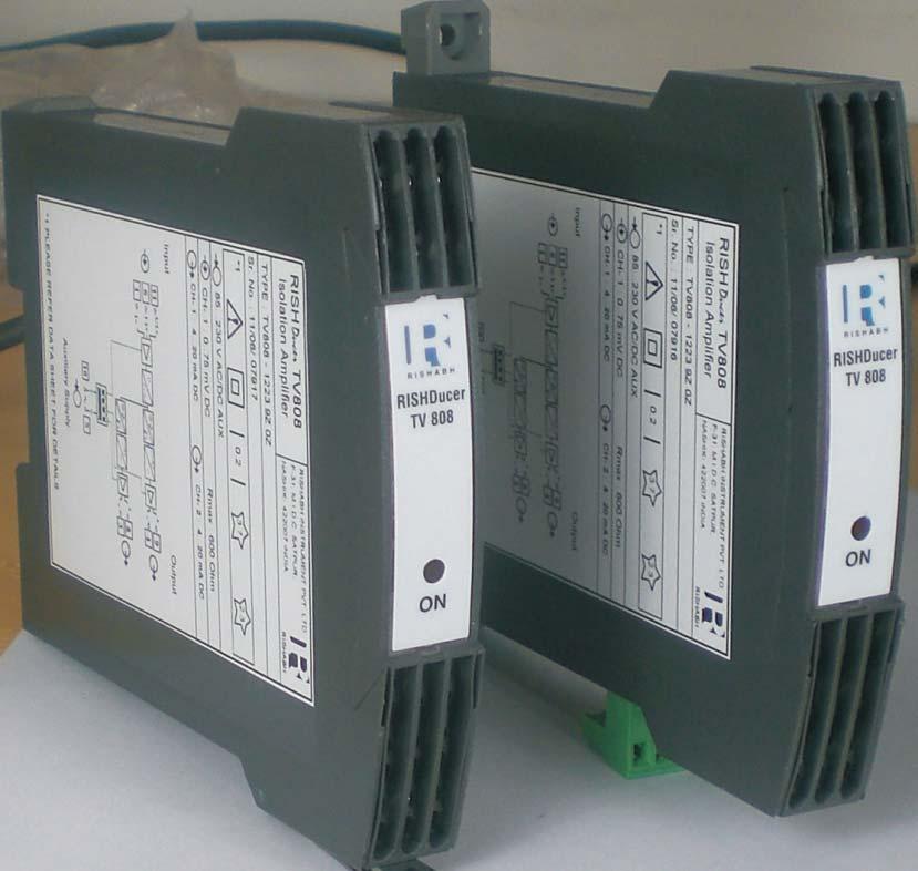
RISH Ducer TV 808, 2 channels Isolating amplifier unipolar / bipolar
 Fig. 1. Isolating amplifier RISH Ducer TV 808 in housing S 17 clipped onto a top - hat rail or screw hole mounting brackets pulled out. Features and Benefits Electric Isolation between input, and power
for DC currents or voltages, temperature sensors, remote sensors or potentiometers Application Principle of operation (Fig. 3) Features / Benefits
 Features / Benefits") for s or voltages, temperature sensors, remote sensors or potentiometers pplication The universal transmitter RISH Ducer V 604 (Figures 1 and 2) convert the input variable a or voltage, or a signal from
for s or voltages, temperature sensors, remote sensors or potentiometers pplication The universal transmitter RISH Ducer V 604 (Figures 1 and 2) convert the input variable a or voltage, or a signal from
SINEAX V 624 Programmable Temperature Transmitter for RTD and TC inputs
 SINEAX V 6 for rail mounting in housing P/7 or P/7 St 00 II () GD Application SINEAX V 6 (Figs. and ) is designed for measuring temperature in combination with thermocouples or resistance thermometers.
RISH Ducer V604 Programmable universal transmitter
 RISH Ducer V64 Programmable universal transmitter Data Sheet Programmable Universal Transmitter RISH Ducer V64 RISH Ducer V64 Fig. Transmitter RISH Ducer V64 in housing S7 clipped on a p-hat rail Fig.
Theta 60R. Technical Data Sheet. Special Features. Fig. 2 Theta R, 2 channel version, in housing S17 hole mounting brackets pulled out.
 Technical Data Sheet Theta 60R 60 R 60 R Fig. Theta R, channel version, in housing S7 clipped on to a top - hat rail. Fig. Theta R, channel version, in housing S7 hole mounting brackets pulled out. Theta
SINEAX V 604 Programmable universal transmitter
 for DC currents or voltages, temperature sensors, remote sensors or potentiometers 0102 II (1) G Application The universal transmitter SINEAX V 604 (Figures 1 and 2) converts the input variable a DC current
for DC currents or voltages, temperature sensors, remote sensors or potentiometers II (1) G Application Features / Benefits
 G Application Features / Benefits") SINEAX VC 603, Programmable for DC currents or voltages, temperature sensors, remote sensors or potentiometers 0102 II (1) G Application The SINEAX VC 603 (Figs. 1 and 2) converts the input variable a
SINEAX VC 603, Programmable for DC currents or voltages, temperature sensors, remote sensors or potentiometers 0102 II (1) G Application The SINEAX VC 603 (Figs. 1 and 2) converts the input variable a
SINEAX I 503 / SINEAX U 504 Transducer for AC current or AC voltage
 Application The transducers SINEAX I 503/U 504 (Figs. 1 and 2) are designed to convert a sinusoidal AC current or voltage into a load independent DC signal proportional to the measured value. This output
SINEAX TV809, 1 channel Programmable Isolating Amplifier
 For electrically insulating, ampliflying and converting DC signals 0102 II (1) Ga II (1) Da Application The purpose of the isolating amplifi er SINEAX TV809 (Fig. 1) is to electrically insulate input and
SINEAX B 811 Power Pack with additional Functions
 SINEA B 8 for intelligent and conventional s, in housing S7 for rail and wall mounting 002 II () G Application The power supply unit SINEA B 8 (Figure ) provides the DC power supply for s and transfers
SINEAX TV 808, 2 channels Isolating Amplifier Unipolar/Bipolar
 SINEAX TV 808, channels For electrically insulating, amplifying and converting DC signals Application The purpose of the isolating amplifi er SINEAX TV 808 (Fig. ) is to electrically insulate input and
SINEAX TI 807 Passive DC signal isolator. SINEAX TI 807 Passive DC signal isolator
 SINEAX TI 807 without power supply, Ex- and non-ex version, in housing N17 or S17 for rail and wall mounting 0102 II (1) G resp. II (2) G Application The signal isolator SINEAX TI 807 serves to electrically
SINEAX TI 807 Passive DC signal isolator
 without power supply, Ex- and non-ex version, in housing N17 or S17 for rail and wall mounting 0102 II (1) G resp. II (2) G Application The signal isolator SINEAX TI 807 serves to electrically insulate
SINEAX TV 808, 1 channel Isolating Amplifier unipolar/bipolar
 For electrically insulating, amplifying and converting DC signals 0102 II (1) G Application The purpose of the isolating amplifi er SINEAX TV 808 (Fig. 1 and 2) is to electrically insulate input and output
RISH Ducer E13 Transducer For Ac Current Or Ac Voltage With Different Characteristics
 RISH Ducer E13 Transducer For c Current Or c Voltage With Different Characteristics Data Sheet For Measurement of C Current or C Voltage Fig. 1. RISH Ducer E13 clipped onto a top - hat rail. Fig. 2. RISH
Plug-in module SIRAX V 606, 1 or 2 channels Programmable Temp. Transmitter for RTD and TC inputs
 Plug-in module, or channels Application The programmable transmitter (Fig. ) is designed for measuring temperature in combination with thermocouples or resistance thermometers. Thermocouple non-linearities
SINEAX TV 808, 1 channel Isolating Amplifier, output Ex or non-ex
 for electrically insulating, amplifying and converting DC signals, also designed for FSK 1 0102 II (1) G Application The purpose of the isolating amplifi er SINEAX TV 808 (Fig. 1) is to electrically insulate
DSCL, DSCP, SCTP. Industrial Loop Isolators and Transmitters DSCL, DSCP, SCTP. Industrial Loop Isolators and Transmitters
 Industrial Loop Isolators and Transmitters DSCL,, SCTP DSCL,, SCTP Industrial Loop Isolators and Transmitters Description Dataforth s DSCL,, and SCTP series of products is a complete family of loop and
Theta 20A / 20V. Technical Data Sheet. Special Features
 Technical Data Sheet Theta 20A / 20V Theta 20A / 20V is used to measure and convert AC Voltage or Current input into a load independent DC current or voltage output signal. Special Features Available in
n True RMS measurement n Fully onsite programmable input voltage range (for CIP-V)
") Tranducers for alternating current/voltage n True RMS measurement n Fully onsite programmable input voltage range (for CIP-V) and input current range (for CIP-I) n Available in single or dual output type
Tranducers for alternating current/voltage n True RMS measurement n Fully onsite programmable input voltage range (for CIP-V) and input current range (for CIP-I) n Available in single or dual output type
RISH Ducer E13 3 channel transducer for AC current and voltage
 RISH Ducer E13 3 channel transducer for C current and voltage The RISH Ducer E13 ( Fig. 1) converts 3 sine wave C current or C voltage into 3 output signals that can serve several receiving instruments
SINEAX U 553 Transducer for AC Voltage
 With power supply RMS value measurement Carrying rail housing P/0 Application he transducer SINEAX U 55 (Fig. ) converts a sinusoidal or a distorted AC voltage into a load independent DC current or a load
SINEAX VC 603, Programmable combined transmitter/alarm unit
 for DC currents or voltages, temperature sensors, remote sensors or potentiometers 0102 II (1) G Application The SINEAX VC 603 (Fig. 1) converts the input variable a DC current or voltage, or a signal
XUA1 AC Voltage and phase balance relay. (August 1996) Manual XUA1 (Revision New)
 Manual XUA1 (Revision New)") XUA1 AC Voltage and phase balance relay (August 1996) Manual XUA1 (Revision New) Woodward Manual XUA1 GB Woodward Governor Company reserves the right to update any portion of this publication at any time.
XUA1 AC Voltage and phase balance relay (August 1996) Manual XUA1 (Revision New) Woodward Manual XUA1 GB Woodward Governor Company reserves the right to update any portion of this publication at any time.
Plug-in module SIRAX TI 807 Passive DC signal isolator
 without power supply, x- and non-x version 0102 II (1) resp. II (2) pplication The signal isolator SIRX TI 807 (Fig. 1) serves to electrically insulate the analogue DC signal in the range 0 20 m which
RISH Ducer E15 TRANSDUCER FOR AC CURRENT OR AC VOLTAGE WITH DIFFERENT CHARACTERISTICS
 RISH Ducer 5 TRNSDUCR FOR C CURRNT OR C VOLTG WITH DIFFRNT CHRCTRISTICS The RISH Ducer 5 transducer (Fig and ) is used where a sine-wave C current or voltage is to be converted into a DC signal proportional
RISH MIT 30 Analog Digital Multimeter with Insulation Resistance Measurement
 RISH MIT 30 Analog Digital Multimeter with Insulation Resistance Measurement Data Sheet Analog Digital Multimeter with Insulation resistance www.rishabh.co.in Page 1 of 6 Version: J 28/12/2011 Application
Theta Hz. Technical Data Sheet. Special Features
 Technical Data Sheet Theta Hz Theta Hz the transducer is used for frequency measurement. The output signal is proportional to measured frequency and is either load independent DC Current or load independent
XP2-R Power and Reverse Power Relay
 XP2-R Power and Reverse Power Relay Manual XP2-R (Revision C) Woodward Manual XP2-RE Woodward reserves the right to update any portion of this publication at any time. Information provided by Woodward
PROGRAMMABLE TRANSDUCER OF DC CURRENT AND DC VOLTAGE SIGNALS P20H TYPE
 PROGRAMMABLE TRANSDUCER OF DC CURRENT AND DC VOLTAGE SIGNALS P20H TYPE USER S MANUAL 1 2 Contents: 1. APPLICATION... 5 2. TRANSDUCER SET...5 3. OPERATIONAL SAFETY... 6 4. INSTALLATION... 7 4.1. Fixing
XUA1 - AC Voltage and phase balance relay
 XUA1 - AC Voltage and phase balance relay Contents 1. Applications and features 2. Design 3. Function 3.1 Voltage supervision 3.2 Unbalanced voltage supervision 4. Operation and settings 4.1 Setting of
XP2-R Power and reverse power relay. (January 2006) Manual XP2-R (Revision New)
 Manual XP2-R (Revision New)") XP2-R Power and reverse power relay (January 2006) Manual XP2-R (Revision New) Woodward Manual XP2-R GB Woodward Governor Company reserves the right to update any portion of this publication at any time.
XP2-R Power and reverse power relay (January 2006) Manual XP2-R (Revision New) Woodward Manual XP2-R GB Woodward Governor Company reserves the right to update any portion of this publication at any time.
SINEAX I 552 Transducer for AC current
 SNEAX 55 With power supply RMS value measurement, with measuring ranges Carrying rail housing P/0 Application he transducer SNEAX 55 (Fig. ) converts a sinusoidal or a distorted AC current into a load
TRANSDUCER of TEMPERATURE and STANDARD SIGNALS P20 type
 TRANSDUCER of TEMPERATURE and STANDARD SIGNALS P20 type USER S MANUAL Contents 1. APPLICATION...5 2. TRANSDUCER SET...5 3. OPERATIONAL SAFETY...6 4. INSTALLATION...7 4.1. Fitting way...7 4.2. External
Temperature transmitter itemp PCP DIN rail TMT 121
 Technical information TI 087R/09/en 510 03671 Temperature transmitter itemp PCP DIN rail TMT 121 Universal temperature transmitter for resistance thermometers (RTD), thermocouples, resistance and voltage
XF2 Frequency Relay. Manual XF2 (Revision A)
") XF2 Frequency Relay Manual XF2 (Revision A) Woodward Manual XF2 GB Woodward Governor Company reserves the right to update any portion of this publication at any time. Information provided by Woodward Governor
XF2 Frequency Relay Manual XF2 (Revision A) Woodward Manual XF2 GB Woodward Governor Company reserves the right to update any portion of this publication at any time. Information provided by Woodward Governor
XU2-AC AC voltage relay. (Februar 1997) Manual XU2-AC (Revision New)
 Manual XU2-AC (Revision New)") XU2-AC AC voltage relay (Februar 1997) Manual XU2-AC (Revision New) Woodward Manual XU2-AC GB Woodward Governor Company reserves the right to update any portion of this publication at any time. Information
XU2-AC AC voltage relay (Februar 1997) Manual XU2-AC (Revision New) Woodward Manual XU2-AC GB Woodward Governor Company reserves the right to update any portion of this publication at any time. Information
High-quality digital indicator for panel mounting Model DI35-M, with multi-function input Model DI35-D, with two inputs for standard signals
 Accessories High-quality digital indicator for panel mounting Model DI35-M, with multi-function input Model DI35-D, with two inputs for standard signals WIKA data sheet AC 80.03 Applications Machine building
DIGITAL PANEL METER N24 AND N25 METER SERIES
 DIGITAL PANEL METER N24 AND N25 METER SERIES USER S MANUAL Contents 1. APPLICATION...5 2. METER SET...5 3. OPERATIONAL SAFETY...6 4. INSTALLATION...7 4.1 Fixing Way...7 4.2 External Connection Diagrams...8
XR1 Rotor Earth Fault Relay. Manual XR1 (Revision C)
") XR1 Rotor Earth Fault Relay Manual XR1 (Revision C) Woodward Manual XR1 (EN) Woodward Governor Company reserves the right to update any portion of this publication at any time. Information provided by
XR1 Rotor Earth Fault Relay Manual XR1 (Revision C) Woodward Manual XR1 (EN) Woodward Governor Company reserves the right to update any portion of this publication at any time. Information provided by
N30P DIGITAL PANEL METER
 N30P DIGITAL PANEL METER Features: NEW Measurement of single-phase network parameters: voltage, current, active, reactive and apparent power, cosj, tgj, j, frequency, active, reactive and apparent energy,
SINEAX V 604s Programmable multifunctional transmitter
 SINEAX V 60s f direct currents, direct voltages, temperature senss, teletransmitters potentiometers 00 SINEAX V60s is a multifunctional transmitter f top-hat rail assembly with the following main characteristics:
XR1 Rotor Earth Fault Relay. (May 2007) Manual XR1 (Revision New)
 Manual XR1 (Revision New)") XR1 Rotor Earth Fault Relay (May 2007) Manual XR1 (Revision New) Woodward Manual XR1 GB Woodward Governor Company reserves the right to update any portion of this publication at any time. Information provided
XR1 Rotor Earth Fault Relay (May 2007) Manual XR1 (Revision New) Woodward Manual XR1 GB Woodward Governor Company reserves the right to update any portion of this publication at any time. Information provided
XI1-I Time overcurrent relay. (Januar 2007) Manual XI1-I (Revision New)
 Manual XI1-I (Revision New)") XI1-I Time overcurrent relay (Januar 2007) Manual XI1-I (Revision New) Woodward Manual XI1-I GB Woodward Governor Company reserves the right to update any portion of this publication at any time. Information
XI1-I Time overcurrent relay (Januar 2007) Manual XI1-I (Revision New) Woodward Manual XI1-I GB Woodward Governor Company reserves the right to update any portion of this publication at any time. Information
SIMEAS-T. Operating Instructions Transducer without auxiliary power. 7KG6111 and 7KG6101. Operating Instructions
 Operating Instructions SIMEAS-T s Operating Instructions Transducer without auxiliary power for alternating current for alternating voltage for alternating voltage with expanded end range 7KG6111 and 7KG6101
RMA42. Technical Information
 Technical Information RMA42 Process transmitter with control unit Digital process transmitter for mounting on a top-hat rail for monitoring and visualizing analog measured values Application Plant and
SINEAX / EURAX 2I1 Passive DC signal isolator
 SINEAX / EURAX I without power supply 0 II () G resp. II () G Application The DC signal isolator SINEAX/EURAX I (Figs. and ) serve to isolate load-independent DC current signals. It suppressed noise voltages
Paperless Recorder PR20
 Technical Information TI 075R/24/ae Paperless Recorder PR20 Economical and time saving recorder operates without the need for paper or pens and is exceedingly simple to operate Application Areas Technological
EMBSIN 281 G Power factor transducer
 EMBSI 8 G Carrying rail housing MBS/SP Application The transducer EMBSI 8 G (Fig. ) measures the power factor between current and voltage of a single or 3-phase balanced network having a sine wave form.
SINEAX G 536 Phase Angle or Power Factor Transducer
 SIEAX G Carrying rail housing P/0 Application The transducer SIEAX G (Fig. ) measures the phase angle or power factor between current and voltage of a single or -phase balanced network having a sine wave
Digital Meters With A Multicolour Bargraph LEL-NA3 one-channel LEL-NA5 one-channel LEL-NA6 two-channel
 Digital Meters With A Multicolour Bargraph LEL-NA3 one-channel LEL-NA5 one-channel LEL-NA6 two-channel Digital-analogue meters of LEL-NA series with a multicolour bargraph have a universal input destined
02/11/2015
 Modem communication plug and play solutions GSM Part number 88970119 For remote control of your application Automatic notification of alarms via SMS (GSM Modem) / email or on a PC with M3 ALARM software.
Coupling Relays and Converters
 Overview Area of application In automation and control engineering it will always be necessary to work with analog signals. The interfaces for analog signals that have established themselves as the standard
N24, N25 DIGITAL PANEL METER
 DIGITAL PANEL METER www.sifamtinsley.co.uk USER S MANUAL Multifunction Meters Transducers & Isolators Temperature Controllers Converters & Recorders Digital Panel Meters DIGITAL PANEL METER Current Transformers
EURAX UI 505, Combined Transducer for AC current and AC voltage
 Plug-in module in Euro-format Application The transducers EURAX UI 505 (Fig. 1) are intended to simultaneous converts of up to 3 sinusoidal AC currents or voltages. Output signals available are load-independent
02/11/2015
 Modem communication plug and play solutions GSM Part number 88970119 For remote control of your application Automatic notification of alarms via SMS (GSM Modem) / email or on a PC with M3 ALARM software.
RISH Multi 12S...18S Analog - Digital multimeters
 RISH Multi S...8S Analog - Digital multimeters Data Sheet Analog - Digital multimeter CAT-I www.rishabh.co.in Page of 7 ersion: //II// C Application It is Analog Digital Multimeter which measures,, +,requency,
P5201 Universal Programmable Transmitters with Galvanic Isolation
 Transmitters - KB0288-2012/09 P5201 Universal Programmable Transmitters with Galvanic Isolation One type of transmitter for all regular resistance and thermocouple sensors. Linearized output signal 4 to
High-Voltage Isolation Amplifiers / Shunt Isolators. VariTrans P 29000
 High-Voltage Isolation Amplifiers / Shunt Isolators VariTrans P 29000 Compact high-voltage isolators with safe galvanic isolation, VariPower broad-range power supply and genuine calibrated range selection.
Plug-in module SIRAX TV 808, 1 channel Isolating Amplifier unipolar/bipolar
 for electrically insulating, amplifying and converting DC signals 0102 II (1) G pplication The purpose of the isolating amplifi er SIRX T 808 (Fig. 1) is to electrically insulate input and output signals,
Isolators A3/1. Temperature Transmitter Field Circuit Non-Ex i Series
 Temperature Transmitter Series 9182 > One unit for nearly all temperature sensors indivdually configurable > Signal duplication possible > Galvanic isolation between input, output, power supply and configuration
Temperature monitoring relays CM-TCS Monitoring relays for monitoring temperatures with a PT100 sensor (2- or 3-wire connection)
") Data sheet Temperature monitoring relays CM-TCS Monitoring relays for monitoring temperatures with a PT100 sensor (2- or 3-wire connection) The temperature monitoring relays CM-TCS monitor overtemperature,
Data sheet Temperature monitoring relays CM-TCS Monitoring relays for monitoring temperatures with a PT100 sensor (2- or 3-wire connection) The temperature monitoring relays CM-TCS monitor overtemperature,
JUMO dtrans T04 Four-wire Transmitter, settable via DIP switch/pc setup program
 JUMO GmbH & Co. KG Delivery address:mackenrodtstraße 14, 36039 Fulda, Germany Postal address: 36035 Fulda, Germany Phone: +49 661 6003-0 Fax: +49 661 6003-607 e-mail: mail@jumo.net Internet: www.jumo.net
02/11/2015
 35 mm - 1 Relay 8A OUR3 Part number 88867103 Multi-function or mono-function Multi-range Multi-voltage Relay output 1 or 2 : 8 A - 250 V (10 A UL) LED status indicator Option of connecting an external
DEIF A/S. Insulation monitor. Type SIM-Q
 Insulation monitor 4921232C Monitoring of insulation resistance on ungrounded AC networks (IT network) Working voltage up to 69V AC, withstands up to V DC Measuring range 1...Mohm or 1...Mohm Alarm on
OPTITEMP TT 20 Technical Datasheet
 OPTITEMP TT 20 Technical Datasheet Analog PC-programmable two-wire transmitters for Pt100 Efficient PC-configuration without recalibration Very stable output Very fast response time The documentation is
Temperature Measurement
 Overview Application transmitters can be used in all industrial sectors. Due to their compact size they can be installed in the connection head type B (DIN 4729) or larger. The following sensors/signal
Installation / Monitoring Technique
 Installation / Monitoring Technique VARIMETER RCM Residual Current Monitor, Type B for AC and DC Systems IP 5883 0249633 IP 5883 ND 5018/035 ND 5018/030 According to IEC/EN 62 020, VDE 0663 For AC and
For non-electrical quantities
 Controlgear 3UG3 monitoring relays 3RS17 interface converters N nsb0346h nsb0348h nsb0775h For electrical quantities For non-electrical quantities 3RS17 interface converter Selection and ordering data
JUMO dtrans T02 Programmable 4-wire Transmitter (Smart Transmitter)
") JUMO GmbH & Co. KG Delivery address:mackenrodtstraße 14, 36039 Fulda, Germany Postal address: 36035 Fulda, Germany Phone: +49 661 6003-0 Fax: +49 661 6003-607 e-mail: mail@jumo.net Internet: www.jumo.net
JUMO GmbH & Co. KG Delivery address:mackenrodtstraße 14, 36039 Fulda, Germany Postal address: 36035 Fulda, Germany Phone: +49 661 6003-0 Fax: +49 661 6003-607 e-mail: mail@jumo.net Internet: www.jumo.net
Insulation monitoring relay CM-IWS.1 For unearthed AC, DC and mixed AC/DC systems up to U n = 250 V AC and 300 V DC
 Data sheet Insulation monitoring relay CM-IWS.1 For unearthed AC, DC and mixed AC/DC systems up to U n = 250 V AC and 300 V DC The CM-IWS.1 serves to monitor insulation resistance in accordance with IEC
POWER \ PHASE ANGLE \ POWER FACTOR TRANSDUCER RISH
 Operating Manual POWER \ PHASE ANGLE \ POWER FACTOR TRANSDUCER RISH CON - P ON O/P1 O/P2 COM RISH CON - P IC :15001143 Rev.B - 17/12/13 POWER \ PHASE ANGLE \ POWER FACTOR TRANSDUCER POWER \ PHASE ANGLE
KINAX 2W2 Programmable Transmitter for Angular Position
 Application The KINAX 2W2 (Figs. 2 and 3) converts the angular position of a shaft into a load independent direct current signal, proportional to the angular position. The unit is contact free and has
High-set undervoltage stage with definitetime. or inverse definite minimum time (IDMT) characteristic. Low-set undervoltage stage with definitetime
 characteristic. Low-set undervoltage stage with definitetime") Issued: 5.06.999 Status: 5.06.999 Version: B/09..00 Data subject to change without notice Features Overvoltage and undervoltage protection Single- or three-phase operation High-set overvoltage stage with
Issued: 5.06.999 Status: 5.06.999 Version: B/09..00 Data subject to change without notice Features Overvoltage and undervoltage protection Single- or three-phase operation High-set overvoltage stage with
JUMO dtrans T02 Programmable 4-wire Transmitter (Smart Transmitter)
") JUMO GmbH & Co. KG Delivery address: Mackenrodtstraße 14 36039 Fulda, Germany Postal address: 36035 Fulda, Germany Phone: +49 661 6003-0 Fax: +49 661 6003-607 E-mail: mail@jumo.net Internet: www.jumo.net
JUMO GmbH & Co. KG Delivery address: Mackenrodtstraße 14 36039 Fulda, Germany Postal address: 36035 Fulda, Germany Phone: +49 661 6003-0 Fax: +49 661 6003-607 E-mail: mail@jumo.net Internet: www.jumo.net
"Modular" versions designed for application-specific functions LCD with 4 lines of 18 characters and configurable backlighting
 Smart "Compact" range with display CD12 Smart Part number 88974043 "Modular" versions designed for application-specific functions LCD with 4 lines of 18 characters and configurable backlighting Type Input
ALPHA 20 MULTIFUNCTION METER (ALPHA SERIES)
") Alpha Series www.sifamtinsley.co.uk Multifunction Meters Transducers & Isolators Temperature Controllers Converters & Recorders Digital Panel Meters Current Transformers Analogue Panel Meters Shunts ALPHA
Alpha Series www.sifamtinsley.co.uk Multifunction Meters Transducers & Isolators Temperature Controllers Converters & Recorders Digital Panel Meters Current Transformers Analogue Panel Meters Shunts ALPHA
Temperature head transmitter itemp PCP TMT 181
 Technical information TI 070R/09/en Mat.-Nr.: 510 01110 Temperature head transmitter itemp PCP TMT 181 Universal head transmitter for resistance thermometers (RTD), thermocouples, resistance and voltage
VariTrans P V. Safe and Sound.
 1000 V. Safe and Sound. VariTrans P 29000 Compact high-voltage isolation amplifiers with safe galvanic isolation, VariPower broad-range power supply and genuine calibrated range selection. Isolation Amplifiers
EURAX VC 603 Programmable combined transmitter/alarm unit
 EURX VC 603 for DC currents or voltages, temperature sensors, remote sensors or potentiometers 010 II (1) GD pplication The combined transmitter/alarm unit EURX VC 603 (Fig. 1) converts the input variable
MCR-T-UI(/NC) MCR-T-UI-E(/NC)
 MCR-T-UI-E(/NC)") MCR-T-UI(/) MCR-T-UI-E(/) Programmable Temperature Transducers for Resistance Thermometers and Thermocouples INTERFACE ata Sheet 00_0_en PHOENIX CONTACT - 0/00 escription A universal temperature measuring
MCR-T-UI(/) MCR-T-UI-E(/) Programmable Temperature Transducers for Resistance Thermometers and Thermocouples INTERFACE ata Sheet 00_0_en PHOENIX CONTACT - 0/00 escription A universal temperature measuring
DIGEM f 96 x 48 EK. Applications. Description
 3-349-002-03 1/7.98 Front panel dimensions: 96 x 48 mm LED display: red or green, 14 mm high Max. display range: 19 999 to + 32 765 Modular connectors for flexible use Simple adjustments at front panel
02/11/2015
 35 mm - 2 Relays 8A PL2R1 Part number 88867455 Multi-function or mono-function Multi-range Multi-voltage Relay output 1 or 2 : 8 A - 250 V (10 A UL) LED status indicator Option of connecting an external
MINI MCR-SL-UI-I-LP-NC
 2-way isolation amplifier Data sheet 105263_en_02 PHOENIX CONTACT 2013-12-13 1 Description The configurable 2-way isolation amplifiers are used to electrically isolate, convert and filter standard signals.
PROGRAMMABLE FIELD TEMPERATURE TRANSMITTER
 Configuration Code TM01 Series 642 Programmable HART Field Temperature The Series 642 programmable HART field temperature transmitter is a 2-wire unit with analog output. It includes input for RTDs; resistance
Isolators A3/1.
 Temperature Transmitter Series 9182 > One unit for nearly all temperature sensors indivdually configurable > Signal duplication possible > Galvanic isolation between input, output, power supply and configuration
JUMO Wtrans Receiver Universal Receiver for JUMO Wireless Measuring Probes
 Data sheet 902931 Page 1/10 JUMO Wtrans Receiver Universal Receiver for JUMO Wireless Measuring Probes For processing physical measurands of the JUMO Wtrans series RS485 interface with Modbus protocol
High precision measurement system for current and voltage IHC-A/B-RM01/03
 Measurement Offset-free and low-noise 16 bit data acquisition system ISA-ASIC Internal sample rate 3,500 Hz Communication Standard RS232- or RS485 interface Advantages Direct measurement on the bus bar
Type CP-S, CP-C & CP-A Switch mode
 Switch mode power CP-S, CP-C & CP-A Switch mode Characteristics CP-S and CP-C range Output current 5 A, 10 A and 20 A Integrated power reserve of up to 50 % 5 A and 10 A devices with pluggable connecting
LINAX 4000L Continuous-line recorder
 -48-852-0 4/2.99 1 to 4 line channels Format 144 mm x 144 mm, mounting depth 250 mm Combined recording table for roll chart (2 m) or fanfold chart (16 m) Measuring channels electrically isolated Rugged
KINAX WT 717 Programmable Transmitter for Angular Position
 Ruggedized version Application The KINAX WT 717 (Fig. 1) converts the angular position of a shaft into a load-independent direct current signal, proportional to the angular position. The unit is contact
Data Sheet 066.8e. Transducers for Active and Reactive Power EW+B 2.2 DGW+B 2.2 VGW+B 2.2 DUW+B 2.2 VUW+B 2.2
 Data Sheet 066.8e Transducers for Active and Reactive Power EW 2.2 DGW 2.2 VGW 2.2 DUW 2.2 VUW 2.2 Application The E/DG/VG/DU/VU W 2.2 power transducers convert all forms of active and reactive power polarity
KINAX SR 719 Programmable Transmitter for Position Feedback
 Position transmitter with NAMUR valve fitting Application The position feedback transmitter KINAX SR 719 (Figs. 1 and 2) is used to measure and transmit linear displacement (stroke) on various types of
Picture. Digital output signal (pressure and temperature) RS-485 Modbus RTU, 9600 bps Protocol details see Data Sheet SW
 RS-485 Modbus RTU, 9600 bps Protocol details see Data Sheet SW") Type: for level measurement Order No.: see Table 1 / Page 4 Features Picture Four wire system Piezoresistive measuring element Pressure measurement relative or absolute Output signal 4-20 ma and RS-485
Type: for level measurement Order No.: see Table 1 / Page 4 Features Picture Four wire system Piezoresistive measuring element Pressure measurement relative or absolute Output signal 4-20 ma and RS-485
RISH EM 3490 SS Kilowatt Hour Energy Meter With Rs485 RISH EM 3490 SS. Application : Product Features: Indication: Pulse Indication:
 Application : RISH Master 3490 SS is a 96mm x 96mm panel mounted kilowatt hour meter it measures active energy with class 1.0 accuracy having auto-resetting 8 digit seven segment LED counter. The unit
GAMMA 12 DIGITAL MULTIMETER
 Gamma 12 www.sifamtinsley.co.uk DATASHEET Issue 1.0 Multifunction Meters Transducers & Isolators Temperature Controllers Converters & Recorders Digital Panel Meters Current Transformers Analogue Panel
09746E00. ATEX / IECEx NEC 505 NEC 506 NEC 500 Class I Class I Class II Class III Zone Zone Division Ex i
 Temperature Transmitter Series 9182 www.stahl.de > One unit for nearly all temperature sensors indivdually configurable > Intrinsically safe input [Ex ia] IIC > Signal duplication possible > Galvanic isolation
TZIF 4. Current-to-Pulse Converter 10/ EN
 TZIF 4 Current-to-Pulse Converter Conversion of direct current or voltage signals into a proportional pulse frequency Integration and average value formation of analog signals for quantity counting/remote
Digital indicator for panel mounting With multi-function input Model DI25
 Accessories Digital indicator for panel mounting With multi-function input Model DI25 WIKA data sheet AC 80.02 Applications Plant construction Machine tools Plastics technology and processing Ventilation