Medical Photonics Lecture 1.2 Optical Engineering
|
|
|
- Dominic Baldwin
- 5 years ago
- Views:
Transcription

1 Medical Photonics Lecture 1.2 Optical Engineering Lecture 9: Instruments I Michael Kempe Winter term
2 2 Contents No Subject Ref Date Detailed Content 1 Introduction Gross Materials, dispersion, ray picture, geometrical approach, paraxial approximation 2 Geometrical optics Gross Ray tracing, matrix approach, aberrations, imaging, Lagrange invariant 3 Components Kempe Lenses, micro-optics, mirrors, prisms, gratings 4 Optical systems Gross Field, aperture, pupil, magnification, infinity cases, lens makers formula, etendue, vignetting 5 Aberrations Gross Introduction, primary aberrations, miscellaneous 6 Diffraction Gross Basic phenomena, wave optics, interference, diffraction calculation, point spread function, transfer function 7 Image quality Kempe Spot, ray aberration curves, PSF and MTF, criteria 8 Instruments I Kempe Human eye, loupe, eyepieces, photographic lenses, zoom lenses, telescopes 9 Instruments II Kempe Microscopic systems, micro objectives, illumination, scanning microscopes, contrasts 10 Instruments III Kempe Medical optical systems, endoscopes, ophthalmic devices, surgical microscopes 11 Optic design Gross Aberration correction, system layouts, optimization, realization aspects 12 Photometry Gross Notations, fundamental laws, Lambert source, radiative transfer, photometry of optical systems, color theory 13 Illumination systems Gross Light sources, basic systems, quality criteria, nonsequential raytrace 14 Metrology Gross Measurement of basic parameters, quality measurements

3 The Human Eye Ref: Wikipedia


4 The Eye of Owl, Cat, Gecko, Insects Ref: Wikipedia
 tear liquid fibres conjunctiva nerve muscle blind")
5 The Human Eye muscle outer skin conjunctiva choroid membrane front chamber fibres retina cornea rear chamber pupil iris lens vitreous body macula (yellow) tear liquid fibres conjunctiva nerve muscle blind spot

6 The Human Field of View < 10 : central < 30 : near-peripheral < 60 : mid-peripheral Ref: Wikipedia

7 The Human Vision
8 Optical Data of the Eye Property relaxed accomodated Refractive power dptr dptr Focal length in air 17.1 mm 14.2 mm Power of the crystalline lens 19 dptr 33 dptr Pupil diameter, smallest value for high brightness 1.5 mm Pupil diameter, largest value for night vision 8.0 mm Abbe number (approx.) Petzval radius mm Location of entrance pupil mm Field of view maximum (vertical) 108 Field of view maximum (horizontal) 200 Field of foveated seeing 5 Diameter eye ball 24 mm Distance rotation point from cornea vertex 13.5 mm Nodal point location 7.33 mm Principal plane location 1.6 mm
9 Eye Data - Overview Terms Sizes and lengths posterior chamber anterior chamber temporal vitreous humor fovea cornea crystalline lens lens capsule optical disc blind spot 7.33 mm 13.5 mm iris nasal retina 1.6 mm F PP' NN' C 1.8 mm 2.5 mm F' 4 mm 0.5 mm 3.6 mm 1.8 mm 15.7 mm 3.6 mm 24.4 mm
10 Refractive Index Distribution of the index along z Smooth index variation n cornea crystalline lens anterior chamber lens capsule vitreous humor retina of crystalline lens n z [mm] z [mm]
11 Spectral Transmission of the Eye Absorption of the eye media prevents retina damage Special truncation of UV and IR contributions 100 T [%] 80 visible after cornea before lens after lens at retina λ [nm]
12 Receptors, rods and cones Cones : Fovea, bright light, color Rods : Peripheral, dim light, no color Blind spot : no receptors Fovea : 2 field eccentric Property cones rods Location (primary) in the fovea outside the fovea Field of view small, 5 large, 108 Resolution and visual acuity large small Brightness sensitivity small, for daylight vision large, vision at night Colour sensitivity yes no Total number of elements 5 million 120 million Limiting brightness 683 lm / W 1699 lm / W Spectral maximum 555 nm 507 nm Macula lutea Periphery Papille, blind spot Range Diameter [mm] Foveola 0.35 Fovea 1.85 Prafovea 2.85 Perifovea mm off axis nasal Cones number :3500 density /mm 2 pitch 2.3 µm density : /mm 2 pitch : 3.2 µm density : 5000/mm 2 pitch : 14.0 µm Rods no rods a few rods density : /mm 2 pitch : 2.5 µm density : 50000/mm 2 pitch : 4.5 µm 1.8 no cones no rods
13 Spectral Sensitivity of the Eye Spectral sensitivity of the eye: - Depends on brightness Daylight / high brightness: cones, peak sensitivity at 550 nm At night/ low Brightness: rods, peak sensitivity at 507 nm, shifted towards blue No color distinction V(λ) night scotopic rods day photopic cones Log V(λ) cyan green λ λ
14 Accomodation Change of accomodation range due to aging 16 D [dpt] dpt 12 mean 4 0 relaxed eye 8 maximum -4 immobile point 4 minimum strongest accomodation age [years] age in years
15 Adaptation Aging effect on adaptation Aging effect on adaptation speed pupil diameter [mm] 8 6 rods Log I thresh [a.u.] 8 7 kink of Helmholtz rod monochromate night blindness 4 2 cones years age in years years 30 years years time [min]
16 Gullstrand Model Eye Six media Crystalline lens with shell Data for relaxed and accomodated eye Simple version : single crystalline lens nm 587 nm 656 nm Relaxed Accomodated Parameter Notation Value Value Focal length object sided f [mm] Focal length image sided f' [mm] Refractive power F [dpt] Location entrance pupil p [mm] Location exit pupil p' [mm] Principal point object sided P [mm] Principal point image sided P' [mm] Nodal point object sided N [mm] Nodal point image sided N' [mm] Length L [mm]
17 Resolution of the Eye Resolution of the eye depends on the shape The quantitative measure is given as angle Rough measure : 2αα cc = Least distance of (comfortable) distictinct vision: 250 mm a) letter 5' d) nonius 10'' b) grating 2' c) two points 1' e) binocular 5'' x' c = 75 µm α c x distance cones s o = 250 mm L = 22 mm
18 18 Testchart Acuity of the Eye Regular testchart E F P T O Z L P E D P E C F D E D F C F D F E L O P Z D D E F P O T E C L E F O D P C T F D P L T C E O P E Z O L C F T D

19 Visual Acuity a) b) Recognition of simple geometrical a shapes : 3a 1. Landolt ring with gap 2. Letter 'E' Blur of image on retina with distance 3a a 5a a 3a distance m image height 25 µm eye 8.9 E mm block letter original blur : a/2 blur : a blur : 2a blur : 3a blur : 4a 3a
 glaucom c) retina defects d)")
20 Eye Diseases Four major defects original a) refraction error b) glaucom c) retina defects d) cataract
21 Spectacles Correction of refraction error by spectacle lenses 1. Myopia (short-sightedness) : negative lens eye binocular 2. Hyperopia (far-sightedness) : positive lens eye binocular
22 Loupe Magnifier Lens close to the eye Reference distance s o = 250 mm relaxed eye Magnification Angle magnification m tan w = tan w o = y f ' y s m w = o so f ' Γmag = s f 0 ' y' s = 250 mm o y lens f lens f L eye s o eye y object w o w m lens

23 Loupe Magnifier General case : Loupe distance d from the eye : Magnification y' s' y s d eye m w s s' = + 1 d + s' f ' virtual image object lens
24 Eyepiece: Basic Setup Eyepieces images a finite image of an instrument to infinity Viewing with a relaxed eye Magnification Objective exit pupil = entrance pupil of eyepiece Eyepiece exit pupil = eye pupil (size: 2-8 mm) Eye relief : distance between last lens surface and eye cornea - required : 15 mm - with eyeglasses : 20 mm Objective exit pupil Γ = 250mm f eyepiece intermediate focus Eyepiece Eye pupil tube length


25 25 Mismatch of Eyepieces Pupil mismatch Eye relief, spherical aberration, eye movement Ref: Smith, Ceragioli, Berry, Telescopes, Eyepieces, Astrographs, Willman-Bell, 2012
26 Evolution of Eyepiece Designs Huygens Loupe Monocentric Ramsden Von-Hofe Plössl Kellner Kerber Erfle Bertele König Erfle type Erfle diffractive Bertele Nagler 1 Erfle type (Zeiss) Aspheric Nagler 2 Scidmore Bertele Wild Dilworth
27 20 arcmin Huygens Eyepiece Distance f 1 + f d = 2 2 Lateral color corrected Intermediate image between lenses, not corrected Performance d Exit pupil (eye position) LONGITUDINAL SPHERICAl ABER. ASTIGMATIC FIELD CURVES DISTORTION Virtual object (image plane of objective) DIOPTER DIOPTER tan sag Distortion (%) 0
28 20 arcmin Kellner Eyepiece Corresponds to Ramsden type Intermediate image accessible Field lens moved Eye lens achromatized LONGITUDINAL SPHERICAl ABER. ASTIGMATIC FIELD CURVES DISTORTION DIOPTER DIOPTER Distortion (%) 0 tan sag
29 Collimation Collimating source radiation: Finite divergence angle is reality Geometrical part due to finite size : Diffraction part: Defocussing contribution to divergence θ G = D f λ θd 2W 2 z θ = sin u f divergence θ G /2 D source u 2W f
30 Typical Photographic Lens Types Type focal length in mm Typical f-number Field of view (full diagonal) in degrees Lens type element number Fisheye Fisheye 7-12 quasi-fisheye Fisheye 6-10 extreme wide-angle retrofocus 9-13 very large angle retrofocus 8-10 wide-angle Double Gauss, retrofocus 6-9 standard Triplet, Tessar, Sonnar, Double Gauss 3-7 short telephoto Double Gauss, telephoto 5 medium telephoto Tessar, telephoto 4-6 long telephoto telephoto 4-7 extreme telephoto telephoto 2-5
31 Requirements of Photo Objective Lenses Large field of view - correction of coma, astigmatism, distortion an field curvature Color correction Resolution - small F-number - usually the sensor is limiting, not diffraction limited correction Smart system, small and light weight - short length - plastic components Additional functionalities - zoom option - focussing - autofocus function - large field viewer
32 Photographic Lenses Tessar Distagon Double Gauss Tele system Super Angulon Wide angle Fish-eye
 c) solid: tan dashed: sag 100 0.")
33 Fish-Eye-Lens Example lens fisheye y -100% 0 100% a) nm 587 nm 656 nm tan sag ideal ν 0 [mm -1 ] cyc/mm 20 cyc/mm 40 cyc/mm 60 cyc/mm b) c) solid: tan dashed: sag field angle 100

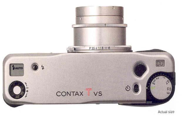

34 Photographic Lens Contax TVS Ref: H. Zügge

35 Handy Phone Objective lenses Examples US L = 4.2 mm, F'=2.8, f = 3.67 mm, 2w=2x34 US L = 6.0 mm, F'=2.8, f = 4.0 mm, 2w=2x31 EP L = 5.37 mm, F'=2.88, f = 3.32 mm, 2w=2x33.9 Olympus 2 L = 7.5 mm, F'=2.8, f = 4.57 mm, 2w=2x33 Ref: T. Steinich


36 Scan Systems 1. Sampling of the field pixel by pixel Signal digitized in the time domain Wide Field 2. Activ: Flying spot scanning Point wise scanning of illumination, often by laser beam Applications: - bar code reader - confocal microscopy - laser radar (e.g. optical coherence tomography) 3. Passiv: Remote sensing Decomposition of object signal into pixels Applications: - Night Vision - monitoring, surveying - missile tracking Source: Confocal
37 Scan Systems: Introduction Scan resolution: Number of resolvable points in the field of view corresponds to angle resolution N L D 2 DExP θ = λ = max Airy Information capacity: 1. Resolvable points 2. Speed of scanning Etendue: product of scan range and scanner area log θ angle resolution holographic scanner polygon mirror growing scan capacity D Mir θmir = DExP θ max resonant galvo scanner galvo scanner acoustic optical modulator electro optical modulator scan speed log v
38 Deflecting Components Different types of deflecting elements Non- Mechanical Deflection Electro-optic Acousto-optic EOD AOD Galvanometric Galvoscanner Scanning Oszillation Holographic Holographic Scanner Electrostatic MEMS Scanner Mechanical Rotation Polygon Rotating Prisms Polygonscanner Dove Prism Translation Lenses and lens arrays
39 Deflecting Components: Polygon Mirrors Rotating mirror with plane facets Pyramidal pyramidal polygon objective lens scan line Prismatic prismatic polygon scan line objective lens


40 Galvanometer and Electrostatic Scanner Galvo scanner MEMS-Scanner Source: scanlab.de Source: researchgate.net
41 42 Scanner Lenses Ideal scanner lens (F-θ lens): h = f θ Flat-field corrected lens: h = f tanθ nonlinear displacement: distortion correction needed Source: thorlabs.com


42 43 Example: Scanner Lens USP : Scan angle 2x30 Monochromatic diffraction limited F-θ-corrected Ref: B. Böhme
Medical Photonics Lecture 1.2 Optical Engineering
 Medical Photonics Lecture 1.2 Optical Engineering Lecture 8: Instruments I 2017-12-14 Michael Kempe Winter term 2017 www.iap.uni-jena.de 2 Contents No Subject Ref Detailed Content 1 Introduction Gross
Lens Design II. Lecture 11: Further topics Herbert Gross. Winter term
 Lens Design II Lecture : Further topics 28--8 Herbert Gross Winter term 27 www.iap.uni-ena.de 2 Preliminary Schedule Lens Design II 27 6.. Aberrations and optimization Repetition 2 23.. Structural modifications
Lens Design II. Lecture 11: Further topics Herbert Gross. Winter term
 Lens Design II Lecture : Further topics 26--2 Herbert Gross Winter term 25 www.iap.uni-ena.de Preliminary Schedule 2 2.. Aberrations and optimization Repetition 2 27.. Structural modifications Zero operands,
OPTICAL SYSTEMS OBJECTIVES
 101 L7 OPTICAL SYSTEMS OBJECTIVES Aims Your aim here should be to acquire a working knowledge of the basic components of optical systems and understand their purpose, function and limitations in terms
Design and Correction of Optical Systems
 Design and Correction of Optical Systems Lecture 12: Optical system classification 2017-06-30 Herbert Gross Summer term 2017 www.iap.uni-jena.de 2 Preliminary Schedule - DCS 2017 1 07.04. Basics 2 21.04.
Design and Correction of Optical Systems
 Design and Correction of Optical Systems Lecture 12: Optical system classification 2015-07-01 Herbert Gross Summer term 2015 www.iap.uni-jena.de 2 Preliminary Schedule 1 15.04. Basics 2 22.04. Materials
Lens Design I. Lecture 3: Properties of optical systems II Herbert Gross. Summer term
 Lens Design I Lecture 3: Properties of optical systems II 207-04-20 Herbert Gross Summer term 207 www.iap.uni-jena.de 2 Preliminary Schedule - Lens Design I 207 06.04. Basics 2 3.04. Properties of optical
Vision. The eye. Image formation. Eye defects & corrective lenses. Visual acuity. Colour vision. Lecture 3.5
 Lecture 3.5 Vision The eye Image formation Eye defects & corrective lenses Visual acuity Colour vision Vision http://www.wired.com/wiredscience/2009/04/schizoillusion/ Perception of light--- eye-brain
Lens Design I. Lecture 3: Properties of optical systems II Herbert Gross. Summer term
 Lens Design I Lecture 3: Properties of optical systems II 205-04-8 Herbert Gross Summer term 206 www.iap.uni-jena.de 2 Preliminary Schedule 04.04. Basics 2.04. Properties of optical systrems I 3 8.04.
Lens Design II. Lecture 8: Special correction topics Herbert Gross. Winter term
 Lens Design II Lecture 8: Special correction topics 2018-12-12 Herbert Gross Winter term 2018 www.iap.uni-jena.de 2 Preliminary Schedule Lens Design II 2018 1 17.10. Aberrations and optimization Repetition
Medical Photonics Lecture 1.2 Optical Engineering
 Medical Photonics Lecture 1.2 Optical Engineering Lecture 10: Instruments III 2018-01-18 Michael Kempe Winter term 2017 www.iap.uni-jena.de 2 Contents No Subject Ref Detailed Content 1 Introduction Gross
Lens Design II. Lecture 8: Special correction features I Herbert Gross. Winter term
 Lens Design II Lecture 8: Special correction features I 2015-12-08 Herbert Gross Winter term 2015 www.iap.uni-jena.de Preliminary Schedule 2 1 20.10. Aberrations and optimization Repetition 2 27.10. Structural
The Human Visual System. Lecture 1. The Human Visual System. The Human Eye. The Human Retina. cones. rods. horizontal. bipolar. amacrine.
 Lecture The Human Visual System The Human Visual System Retina Optic Nerve Optic Chiasm Lateral Geniculate Nucleus (LGN) Visual Cortex The Human Eye The Human Retina Lens rods cones Cornea Fovea Optic
Optical Design with Zemax
 Optical Design with Zemax Lecture : Correction II 3--9 Herbert Gross Summer term www.iap.uni-jena.de Correction II Preliminary time schedule 6.. Introduction Introduction, Zemax interface, menues, file
Lens Design II. Lecture 8: Special correction features I Herbert Gross. Winter term
 Lens Design II Lecture 8: Special correction features I 2017-12-04 Herbert Gross Winter term 2017 www.iap.uni-jena.de 2 Preliminary Schedule Lens Design II 2017 1 16.10. Aberrations and optimization Repetition
Chapter 25. Optical Instruments
 Chapter 25 Optical Instruments Optical Instruments Analysis generally involves the laws of reflection and refraction Analysis uses the procedures of geometric optics To explain certain phenomena, the wave
Lecture 8. Lecture 8. r 1
 Lecture 8 Achromat Design Design starts with desired Next choose your glass materials, i.e. Find P D P D, then get f D P D K K Choose radii (still some freedom left in choice of radii for minimization
GEOMETRICAL OPTICS AND OPTICAL DESIGN
 GEOMETRICAL OPTICS AND OPTICAL DESIGN Pantazis Mouroulis Associate Professor Center for Imaging Science Rochester Institute of Technology John Macdonald Senior Lecturer Physics Department University of
Chapter 36. Image Formation
 Chapter 36 Image Formation Image of Formation Images can result when light rays encounter flat or curved surfaces between two media. Images can be formed either by reflection or refraction due to these
Chapter 36. Image Formation
 Chapter 36 Image Formation Notation for Mirrors and Lenses The object distance is the distance from the object to the mirror or lens Denoted by p The image distance is the distance from the image to the
Introduction. Geometrical Optics. Milton Katz State University of New York. VfeWorld Scientific New Jersey London Sine Singapore Hong Kong
 Introduction to Geometrical Optics Milton Katz State University of New York VfeWorld Scientific «New Jersey London Sine Singapore Hong Kong TABLE OF CONTENTS PREFACE ACKNOWLEDGMENTS xiii xiv CHAPTER 1:
Lens Design I. Lecture 5: Advanced handling I Herbert Gross. Summer term
 Lens Design I Lecture 5: Advanced handling I 2018-05-17 Herbert Gross Summer term 2018 www.iap.uni-jena.de 2 Preliminary Schedule - Lens Design I 2018 1 12.04. Basics 2 19.04. Properties of optical systems
Optical Components for Laser Applications. Günter Toesko - Laserseminar BLZ im Dezember
 Günter Toesko - Laserseminar BLZ im Dezember 2009 1 Aberrations An optical aberration is a distortion in the image formed by an optical system compared to the original. It can arise for a number of reasons
Optical Design with Zemax for PhD
 Optical Design with Zemax for PhD Lecture 7: Optimization II 26--2 Herbert Gross Winter term 25 www.iap.uni-jena.de 2 Preliminary Schedule No Date Subject Detailed content.. Introduction 2 2.2. Basic Zemax
Index. B Back focal length, 12 Beam expander, 35 Berek, Max, 244 Binary phase grating, 326 Buried surface, 131,
 About the Author The author studied Technical Physics at the Technical University of Delft, The Netherlands. He obtained a master s degree in 1965 with a thesis on the fabrication of lasers. After military
ECEN 4606, UNDERGRADUATE OPTICS LAB
 ECEN 4606, UNDERGRADUATE OPTICS LAB Lab 2: Imaging 1 the Telescope Original Version: Prof. McLeod SUMMARY: In this lab you will become familiar with the use of one or more lenses to create images of distant
Lens Design II. Lecture 2: Structural modifications Herbert Gross. Winter term
 Lens Design II Lecture 2: Structural modifications 26--26 Herbert Gross Winter term 26 www.iap.uni-jena.de 2 Preliminary Schedule 9.. Aberrations and optimization Repetition 2 26.. Structural modifications
PHYSICS. Chapter 35 Lecture FOR SCIENTISTS AND ENGINEERS A STRATEGIC APPROACH 4/E RANDALL D. KNIGHT
 PHYSICS FOR SCIENTISTS AND ENGINEERS A STRATEGIC APPROACH 4/E Chapter 35 Lecture RANDALL D. KNIGHT Chapter 35 Optical Instruments IN THIS CHAPTER, you will learn about some common optical instruments and
Phys 531 Lecture 9 30 September 2004 Ray Optics II. + 1 s i. = 1 f
 Phys 531 Lecture 9 30 September 2004 Ray Optics II Last time, developed idea of ray optics approximation to wave theory Introduced paraxial approximation: rays with θ 1 Will continue to use Started disussing
Lens Design I. Lecture 10: Optimization II Herbert Gross. Summer term
 Lens Design I Lecture : Optimization II 5-6- Herbert Gross Summer term 5 www.iap.uni-jena.de Preliminary Schedule 3.. Basics.. Properties of optical systrems I 3 7.5..5. Properties of optical systrems
Warren J. Smith Chief Scientist, Consultant Rockwell Collins Optronics Carlsbad, California
 Modern Optical Engineering The Design of Optical Systems Warren J. Smith Chief Scientist, Consultant Rockwell Collins Optronics Carlsbad, California Fourth Edition Me Graw Hill New York Chicago San Francisco
Chapter 3 Optical Systems
 Chapter 3 Optical Systems The Human Eye [Reading Assignment, Hecht 5.7.1-5.7.3; see also Smith Chapter 5] retina aqueous vitreous fovea-macula cornea lens blind spot optic nerve iris cornea f b aqueous
Microscopy. Lecture 2: Optical System of the Microscopy II Herbert Gross. Winter term
 Microscopy Lecture 2: Optical System of the Microscopy II 212-1-22 Herbert Gross Winter term 212 www.iap.uni-jena.de Preliminary time schedule 2 No Date Main subject Detailed topics Lecturer 1 15.1. Optical
Physics Chapter Review Chapter 25- The Eye and Optical Instruments Ethan Blitstein
 Physics Chapter Review Chapter 25- The Eye and Optical Instruments Ethan Blitstein The Human Eye As light enters through the human eye it first passes through the cornea (a thin transparent membrane of
TOPICS Recap of PHYS110-1 lecture Physical Optics - 4 lectures EM spectrum and colour Light sources Interference and diffraction Polarization
 TOPICS Recap of PHYS110-1 lecture Physical Optics - 4 lectures EM spectrum and colour Light sources Interference and diffraction Polarization Lens Aberrations - 3 lectures Spherical aberrations Coma, astigmatism,
Applied Optics. , Physics Department (Room #36-401) , ,
 , ,") Applied Optics Professor, Physics Department (Room #36-401) 2290-0923, 019-539-0923, shsong@hanyang.ac.kr Office Hours Mondays 15:00-16:30, Wednesdays 15:00-16:30 TA (Ph.D. student, Room #36-415) 2290-0921,
Applied Optics Professor, Physics Department (Room #36-401) 2290-0923, 019-539-0923, shsong@hanyang.ac.kr Office Hours Mondays 15:00-16:30, Wednesdays 15:00-16:30 TA (Ph.D. student, Room #36-415) 2290-0921,
Lecture 2: Geometrical Optics. Geometrical Approximation. Lenses. Mirrors. Optical Systems. Images and Pupils. Aberrations.
 Lecture 2: Geometrical Optics Outline 1 Geometrical Approximation 2 Lenses 3 Mirrors 4 Optical Systems 5 Images and Pupils 6 Aberrations Christoph U. Keller, Leiden Observatory, keller@strw.leidenuniv.nl
Reading: Lenses and Mirrors; Applications Key concepts: Focal points and lengths; real images; virtual images; magnification; angular magnification.
 Reading: Lenses and Mirrors; Applications Key concepts: Focal points and lengths; real images; virtual images; magnification; angular magnification. 1.! Questions about objects and images. Can a virtual
Optical Design with Zemax
 Optical Design with Zemax Lecture 9: Advanced handling 2014-06-13 Herbert Gross Sommer term 2014 www.iap.uni-jena.de 2 Preliminary Schedule 1 11.04. Introduction 2 25.04. Properties of optical systems
Lens Design I. Lecture 10: Optimization II Herbert Gross. Summer term
 Lens Design I Lecture : Optimization II 8-6- Herbert Gross Summer term 8 www.iap.uni-jena.de Preliminary Schedule - Lens Design I 8.4. Basics 9.4. Properties of optical systems I 3 6.4. Properties of optical
Photography (cont d)
") Lecture 13 Ch. 4 Photography continued Ch. 5 The Eye Feb. 23, 2010 Exams will be back on Feb. 25 Homework 5 is due Feb. 25 Read all of Ch. 5. on The Eye. 1 Photography (cont d) Polarizing and haze filters
Lecture 13 Ch. 4 Photography continued Ch. 5 The Eye Feb. 23, 2010 Exams will be back on Feb. 25 Homework 5 is due Feb. 25 Read all of Ch. 5. on The Eye. 1 Photography (cont d) Polarizing and haze filters
Opti 415/515. Introduction to Optical Systems. Copyright 2009, William P. Kuhn
 Opti 415/515 Introduction to Optical Systems 1 Optical Systems Manipulate light to form an image on a detector. Point source microscope Hubble telescope (NASA) 2 Fundamental System Requirements Application
Chapter 6 Human Vision
 Chapter 6 Notes: Human Vision Name: Block: Human Vision The Humane Eye: 8) 1) 2) 9) 10) 4) 5) 11) 12) 3) 13) 6) 7) Functions of the Eye: 1) Cornea a transparent tissue the iris and pupil; provides most
INTRODUCTION THIN LENSES. Introduction. given by the paraxial refraction equation derived last lecture: Thin lenses (19.1) = 1. Double-lens systems
 = 1. Double-lens systems") Chapter 9 OPTICAL INSTRUMENTS Introduction Thin lenses Double-lens systems Aberrations Camera Human eye Compound microscope Summary INTRODUCTION Knowledge of geometrical optics, diffraction and interference,
Chapter 9 OPTICAL INSTRUMENTS Introduction Thin lenses Double-lens systems Aberrations Camera Human eye Compound microscope Summary INTRODUCTION Knowledge of geometrical optics, diffraction and interference,
25 cm. 60 cm. 50 cm. 40 cm.
 Geometrical Optics 7. The image formed by a plane mirror is: (a) Real. (b) Virtual. (c) Erect and of equal size. (d) Laterally inverted. (e) B, c, and d. (f) A, b and c. 8. A real image is that: (a) Which
OPTI-201/202 Geometrical and Instrumental Optics Copyright 2018 John E. Greivenkamp. Section 16. The Eye
 16-1 Section 16 The Eye The Eye Ciliary Muscle Iris Pupil Optical Axis Visual Axis 16-2 Cornea Right Eye Horizontal Section Zonules Crystalline Lens Vitreous Sclera Retina Macula And Fovea Optic Nerve
Science 8 Unit 2 Pack:
 Science 8 Unit 2 Pack: Name Page 0 Section 4.1 : The Properties of Waves Pages By the end of section 4.1 you should be able to understand the following: Waves are disturbances that transmit energy from
Chapter 34 Geometric Optics (also known as Ray Optics) by C.-R. Hu
 by C.-R. Hu") Chapter 34 Geometric Optics (also known as Ray Optics) by C.-R. Hu 1. Principles of image formation by mirrors (1a) When all length scales of objects, gaps, and holes are much larger than the wavelength
Chapter 34 Geometric Optics (also known as Ray Optics) by C.-R. Hu 1. Principles of image formation by mirrors (1a) When all length scales of objects, gaps, and holes are much larger than the wavelength
Introduction to Light Microscopy. (Image: T. Wittman, Scripps)
") Introduction to Light Microscopy (Image: T. Wittman, Scripps) The Light Microscope Four centuries of history Vibrant current development One of the most widely used research tools A. Khodjakov et al. Major
Introduction to Light Microscopy (Image: T. Wittman, Scripps) The Light Microscope Four centuries of history Vibrant current development One of the most widely used research tools A. Khodjakov et al. Major
Optical Design with Zemax for PhD - Basics
 Optical Design with Zemax for PhD - Basics Lecture 3: Properties of optical sstems II 2013-05-30 Herbert Gross Summer term 2013 www.iap.uni-jena.de 2 Preliminar Schedule No Date Subject Detailed content
Lens Design I. Lecture 5: Advanced handling I Herbert Gross. Summer term
 Lens Design I Lecture 5: Advanced handling I 2015-05-11 Herbert Gross Summer term 2015 www.iap.uni-jena.de 2 Preliminary Schedule 1 13.04. Basics 2 20.04. Properties of optical systrems I 3 27.05. Properties
Refraction of Light. Refraction of Light
 1 Refraction of Light Activity: Disappearing coin Place an empty cup on the table and drop a penny in it. Look down into the cup so that you can see the coin. Move back away from the cup slowly until the
Section 22. The Eye The Eye. Ciliary Muscle. Sclera. Zonules. Macula And Fovea. Iris. Retina. Pupil. Optical Axis.
 Section 22 The Eye 22-1 The Eye Optical Axis Visual Axis Pupil Iris Cornea Right Eye Horizontal Section Ciliary Muscle Zonules Crystalline Lens Vitreous Sclera Retina Macula And Fovea Optic Nerve 22-2
Chapter 29/30. Wave Fronts and Rays. Refraction of Sound. Dispersion in a Prism. Index of Refraction. Refraction and Lenses
 Chapter 29/30 Refraction and Lenses Refraction Refraction the bending of waves as they pass from one medium into another. Caused by a change in the average speed of light. Analogy A car that drives off
Lecture 4: Geometrical Optics 2. Optical Systems. Images and Pupils. Rays. Wavefronts. Aberrations. Outline
 Lecture 4: Geometrical Optics 2 Outline 1 Optical Systems 2 Images and Pupils 3 Rays 4 Wavefronts 5 Aberrations Christoph U. Keller, Leiden University, keller@strw.leidenuniv.nl Lecture 4: Geometrical
30 Lenses. Lenses change the paths of light.
 Lenses change the paths of light. A light ray bends as it enters glass and bends again as it leaves. Light passing through glass of a certain shape can form an image that appears larger, smaller, closer,
ECEG105/ECEU646 Optics for Engineers Course Notes Part 4: Apertures, Aberrations Prof. Charles A. DiMarzio Northeastern University Fall 2008
 ECEG105/ECEU646 Optics for Engineers Course Notes Part 4: Apertures, Aberrations Prof. Charles A. DiMarzio Northeastern University Fall 2008 July 2003+ Chuck DiMarzio, Northeastern University 11270-04-1
Advanced Lens Design
 Advanced Lens Design Lecture 3: Aberrations I 214-11-4 Herbert Gross Winter term 214 www.iap.uni-jena.de 2 Preliminary Schedule 1 21.1. Basics Paraxial optics, imaging, Zemax handling 2 28.1. Optical systems
Physics 11. Unit 8 Geometric Optics Part 2
 Physics 11 Unit 8 Geometric Optics Part 2 (c) Refraction (i) Introduction: Snell s law Like water waves, when light is traveling from one medium to another, not only does its wavelength, and in turn the
10/8/ dpt. n 21 = n n' r D = The electromagnetic spectrum. A few words about light. BÓDIS Emőke 02 October Optical Imaging in the Eye
 A few words about light BÓDIS Emőke 02 October 2012 Optical Imaging in the Eye Healthy eye: 25 cm, v1 v2 Let s determine the change in the refractive power between the two extremes during accommodation!
EE-527: MicroFabrication
 EE-57: MicroFabrication Exposure and Imaging Photons white light Hg arc lamp filtered Hg arc lamp excimer laser x-rays from synchrotron Electrons Ions Exposure Sources focused electron beam direct write
Optical System Design
 Phys 531 Lecture 12 14 October 2004 Optical System Design Last time: Surveyed examples of optical systems Today, discuss system design Lens design = course of its own (not taught by me!) Try to give some
PHY385H1F Introductory Optics. Practicals Session 7 Studying for Test 2
 PHY385H1F Introductory Optics Practicals Session 7 Studying for Test 2 Entrance Pupil & Exit Pupil A Cooke-triplet consists of three thin lenses in succession, and is often used in cameras. It was patented
Refraction, Lenses, and Prisms
 CHAPTER 16 14 SECTION Sound and Light Refraction, Lenses, and Prisms KEY IDEAS As you read this section, keep these questions in mind: What happens to light when it passes from one medium to another? How
[ Summary. 3i = 1* 6i = 4J;
 the projections at angle 2. We calculate the difference between the measured projections at angle 2 (6 and 14) and the projections based on the previous esti mate (top row: 2>\ + 6\ = 10; same for bottom
Chapters 1 & 2. Definitions and applications Conceptual basis of photogrammetric processing
 Chapters 1 & 2 Chapter 1: Photogrammetry Definitions and applications Conceptual basis of photogrammetric processing Transition from two-dimensional imagery to three-dimensional information Automation
VISUAL PHYSICS ONLINE DEPTH STUDY: ELECTRON MICROSCOPES
 VISUAL PHYSICS ONLINE DEPTH STUDY: ELECTRON MICROSCOPES Shortly after the experimental confirmation of the wave properties of the electron, it was suggested that the electron could be used to examine objects
Section 1: Sound. Sound and Light Section 1
 Sound and Light Section 1 Section 1: Sound Preview Key Ideas Bellringer Properties of Sound Sound Intensity and Decibel Level Musical Instruments Hearing and the Ear The Ear Ultrasound and Sonar Sound
Exam 3--PHYS 151--S15
 Name: Class: Date: Exam 3--PHYS 151--S15 Multiple Choice Identify the choice that best completes the statement or answers the question. 1. Consider this diagram of the eye and answer the following questions.
Cardinal Points of an Optical System--and Other Basic Facts
 Cardinal Points of an Optical System--and Other Basic Facts The fundamental feature of any optical system is the aperture stop. Thus, the most fundamental optical system is the pinhole camera. The image
Chapter 25: Applied Optics. PHY2054: Chapter 25
 Chapter 25: Applied Optics PHY2054: Chapter 25 1 Operation of the Eye 24 mm PHY2054: Chapter 25 2 Essential parts of the eye Cornea transparent outer structure Pupil opening for light Lens partially focuses
GIST OF THE UNIT BASED ON DIFFERENT CONCEPTS IN THE UNIT (BRIEFLY AS POINT WISE). RAY OPTICS
. RAY OPTICS") 209 GIST OF THE UNIT BASED ON DIFFERENT CONCEPTS IN THE UNIT (BRIEFLY AS POINT WISE). RAY OPTICS Reflection of light: - The bouncing of light back into the same medium from a surface is called reflection
209 GIST OF THE UNIT BASED ON DIFFERENT CONCEPTS IN THE UNIT (BRIEFLY AS POINT WISE). RAY OPTICS Reflection of light: - The bouncing of light back into the same medium from a surface is called reflection
Lecture 17. Image formation Ray tracing Calculation. Lenses Convex Concave. Mirrors Convex Concave. Optical instruments
 Lecture 17. Image formation Ray tracing Calculation Lenses Convex Concave Mirrors Convex Concave Optical instruments Image formation Laws of refraction and reflection can be used to explain how lenses
Average: Standard Deviation: Max: 99 Min: 40
 1 st Midterm Exam Average: 83.1 Standard Deviation: 12.0 Max: 99 Min: 40 Please contact me to fix an appointment, if you took less than 65. Chapter 33 Lenses and Op/cal Instruments Units of Chapter 33
MULTIPLE CHOICE. Choose the one alternative that best completes the statement or answers the question.
 Exam Name MULTIPLE CHOICE. Choose the one alternative that best completes the statement or answers the question. 1) A plane mirror is placed on the level bottom of a swimming pool that holds water (n =
Exam Preparation Guide Geometrical optics (TN3313)
") Exam Preparation Guide Geometrical optics (TN3313) Lectures: September - December 2001 Version of 21.12.2001 When preparing for the exam, check on Blackboard for a possible newer version of this guide.
Exam Preparation Guide Geometrical optics (TN3313) Lectures: September - December 2001 Version of 21.12.2001 When preparing for the exam, check on Blackboard for a possible newer version of this guide.
Sequential Ray Tracing. Lecture 2
 Sequential Ray Tracing Lecture 2 Sequential Ray Tracing Rays are traced through a pre-defined sequence of surfaces while travelling from the object surface to the image surface. Rays hit each surface once
Vision 1. Physical Properties of Light. Overview of Topics. Light, Optics, & The Eye Chaudhuri, Chapter 8
 Vision 1 Light, Optics, & The Eye Chaudhuri, Chapter 8 1 1 Overview of Topics Physical Properties of Light Physical properties of light Interaction of light with objects Anatomy of the eye 2 3 Light A
The eye & corrective lenses
 Phys 102 Lecture 20 The eye & corrective lenses 1 Today we will... Apply concepts from ray optics & lenses Simple optical instruments the camera & the eye Learn about the human eye Accommodation Myopia,
Design and Correction of optical Systems
 Design and Correction of optical Sstems Part 5: Properties of Optical Sstems Summer term 2012 Herbert Gross Overview 2 1. Basics 2012-04-18 2. Materials 2012-04-25 3. Components 2012-05-02 4. Paraxial
Properties of optical instruments
 Properties of optical instruments Visual optical systems part 1: afocal systems (telescope type) A basic optical description of the eye Power: 60 diopters (at rest) Equivalent to a single spherical surface,
Optical Design of. Microscopes. George H. Seward. Tutorial Texts in Optical Engineering Volume TT88. SPIE PRESS Bellingham, Washington USA
 Optical Design of Microscopes George H. Seward Tutorial Texts in Optical Engineering Volume TT88 SPIE PRESS Bellingham, Washington USA Preface xiii Chapter 1 Optical Design Concepts /1 1.1 A Value Proposition
Explanation of Aberration and Wavefront
 Explanation of Aberration and Wavefront 1. What Causes Blur? 2. What is? 4. What is wavefront? 5. Hartmann-Shack Aberrometer 6. Adoption of wavefront technology David Oh 1. What Causes Blur? 2. What is?
Chapter 2 Optical Instruments (Paraxial Approximation)
") Chapter 2 Optical Instruments (Paraxial Approximation) We give only a short description of the most important optical instruments. For more details see the textbooks, e.g. Hecht [1] or Longhurst [2]. 2.1
Chapter 2 Optical Instruments (Paraxial Approximation) We give only a short description of the most important optical instruments. For more details see the textbooks, e.g. Hecht [1] or Longhurst [2]. 2.1
EE119 Introduction to Optical Engineering Spring 2002 Final Exam. Name:
 EE119 Introduction to Optical Engineering Spring 2002 Final Exam Name: SID: CLOSED BOOK. FOUR 8 1/2 X 11 SHEETS OF NOTES, AND SCIENTIFIC POCKET CALCULATOR PERMITTED. TIME ALLOTTED: 180 MINUTES Fundamental
Chapter 36. Image Formation
 Chapter 36 Image Formation Image of Formation Images can result when light rays encounter flat or curved surfaces between two media. Images can be formed either by reflection or refraction due to these
HOLIDAY HOME WORK PHYSICS CLASS-12B AUTUMN BREAK 2018
 HOLIDAY HOME WK PHYSICS CLASS-12B AUTUMN BREAK 2018 NOTE: 1. THESE QUESTIONS ARE FROM PREVIOUS YEAR BOARD PAPERS FROM 2009-2018 CHAPTERS EMI,AC,OPTICS(BUT TRY TO SOLVE ONLY NON-REPEATED QUESTION) QUESTION
Physics 1230: Light and Color
 Physics 1230: Light and Color Exam 4 cancelled: Exam extra credit assignment will be due Wed. at 5PM Extra credit to improve exam scores! HW9: Due today, Monday, 5PM FCQ at end of lecture. Lecture 13:
Lenses- Worksheet. (Use a ray box to answer questions 3 to 7)
") Lenses- Worksheet 1. Look at the lenses in front of you and try to distinguish the different types of lenses? Describe each type and record its characteristics. 2. Using the lenses in front of you, look
Lenses- Worksheet 1. Look at the lenses in front of you and try to distinguish the different types of lenses? Describe each type and record its characteristics. 2. Using the lenses in front of you, look
11/23/11. A few words about light nm The electromagnetic spectrum. BÓDIS Emőke 22 November Schematic structure of the eye
 11/23/11 A few words about light 300-850nm 400-800 nm BÓDIS Emőke 22 November 2011 The electromagnetic spectrum see only 1/70 of the electromagnetic spectrum The External Structure: The Immediate Structure:
Imaging and Aberration Theory
 Imaging and Aberration Theory Lecture 7: Distortion and coma 2014-12-11 Herbert Gross Winter term 2014 www.iap.uni-jena.de 2 Preliminary time schedule 1 30.10. Paraxial imaging paraxial optics, fundamental
PHYS 202 OUTLINE FOR PART III LIGHT & OPTICS
 PHYS 202 OUTLINE FOR PART III LIGHT & OPTICS Electromagnetic Waves A. Electromagnetic waves S-23,24 1. speed of waves = 1/( o o ) ½ = 3 x 10 8 m/s = c 2. waves and frequency: the spectrum (a) radio red
Chapter 3 Op+cal Instrumenta+on
 Chapter 3 Op+cal Instrumenta+on 3-1 Stops, Pupils, and Windows 3-4 The Camera 3-5 Simple Magnifiers and Eyepieces 3-6 Microscopes 3-7 Telescopes Today (2011-09-22) 1. Magnifiers 2. Camera 3. Resolution
Chapter 24 Geometrical Optics. Copyright 2010 Pearson Education, Inc.
 Chapter 24 Geometrical Optics Lenses convex (converging) concave (diverging) Mirrors Ray Tracing for Mirrors We use three principal rays in finding the image produced by a curved mirror. The parallel ray
R.B.V.R.R. WOMEN S COLLEGE (AUTONOMOUS) Narayanaguda, Hyderabad.
 Narayanaguda, Hyderabad.") R.B.V.R.R. WOMEN S COLLEGE (AUTONOMOUS) Narayanaguda, Hyderabad. DEPARTMENT OF PHYSICS QUESTION BANK FOR SEMESTER III PAPER III OPTICS UNIT I: 1. MATRIX METHODS IN PARAXIAL OPTICS 2. ABERATIONS UNIT II
R.B.V.R.R. WOMEN S COLLEGE (AUTONOMOUS) Narayanaguda, Hyderabad. DEPARTMENT OF PHYSICS QUESTION BANK FOR SEMESTER III PAPER III OPTICS UNIT I: 1. MATRIX METHODS IN PARAXIAL OPTICS 2. ABERATIONS UNIT II
Lecture Outline Chapter 27. Physics, 4 th Edition James S. Walker. Copyright 2010 Pearson Education, Inc.
 Lecture Outline Chapter 27 Physics, 4 th Edition James S. Walker Chapter 27 Optical Instruments Units of Chapter 27 The Human Eye and the Camera Lenses in Combination and Corrective Optics The Magnifying
Chapter 34: Geometric Optics
 Chapter 34: Geometric Optics It is all about images How we can make different kinds of images using optical devices Optical device example: mirror, a piece of glass, telescope, microscope, kaleidoscope,
Grade 8. Light and Optics. Unit exam
 Grade 8 Light and Optics Unit exam Unit C - Light and Optics 1. Over the years many scientists have contributed to our understanding of light. All the properties listed below about light are correct except:
Chapter 9 - Ray Optics and Optical Instruments. The image distance can be obtained using the mirror formula:
 Question 9.1: A small candle, 2.5 cm in size is placed at 27 cm in front of a concave mirror of radius of curvature 36 cm. At what distance from the mirror should a screen be placed in order to obtain