SAMUEL ROBERTS NOBLE ELECTRON MICROSCOPY LABORATORY. Operating Procedures for the Zeiss 9 S-2. Transmission Electron Microscope
|
|
|
- Melvyn Johnston
- 5 years ago
- Views:
Transcription
1 1 SAMUEL ROBERTS NOBLE ELECTRON MICROSCOPY LABORATORY Operating Procedures for the Zeiss 9 S-2 Transmission Electron Microscope Prepared by Dr. Scott D. Russell Department of Botany and Microbiology September, 1982 revised January, 1983
2 2 The following manual is designed to instruct beginning to advanced users on the operation of the Zeiss 9 transmission electron microscope. Much more detail is provided than most users will ever require. Instructions provided on the following white pages are important to all users; however, instructions provided on pink sheets require alignment of the entire microscope. In order to keep the microscope operational at all times, only faculty members, EM lab technicians and advanced users will be permitted to do full column alignment. Please be familiar with the emergency shutdown procedures listed below. Formal instruction on the use of this instrument is provided jointly by the Department of Botany and Microbiology and the Department of Zoology through BOT/ZOO 5063, "Principles and Techniques of Transmission Electron Microscopy". Operators are checked out as "learners" in this course. Use of the instrument following the completion of this course requires permission of the director and operators are then checked out as "day operators". (Refer to EML Operating Policy for further details.) WARNING: Do not change valve positions (buttons 64-66) when the servomotor is in operation as this will overload the servomotor and put the scope out of operation for the day. Do not switch either of switches 18a or 20a or the scope will require full column alignment (30 minute delay--minimum) EMERGENCY SHUT-DOWN PROCEDURES 1. Immediately turn the T-switch downward and to the left to turn off filament and high voltage. 2. Press vacuum button "0" (65) to seal off the column from the pumps and to turn off diffusion pump heater. 3. Turn main switch to "0" after valving from step 2 has been completed.
3 3 TABLE OF CONTENTS 1. Turning on the microscope Obtaining an electron beam Specimen changing and insertion Beam alignment Aligning the objective and intermediate apertures Taking a micrograph Venting the column Changing film in the camera Obtaining film from the dessicator Adjustment of the stigmator Replacing a filament Locating a lost electron beam Alignment of condenser aperture Condenser lens alignment Scanning grids at low magnification Locating beam by "wobbling" Locating beam with disaligned column Alignment of image-forming lenses Kodak film information Diagram of Zeiss 9 control panels Labeled images of Zeiss 9 microscope Microscope calibration T. E. M. darkroom policy Operations schematics...19
4 4 Turning on the Microscope 1. Turn main switch (68) to I. Indicator lights (10, 67) should be lit. 2. Indicator light (10) will turn on for approximately 3 minutes and then turn off. If at any time this light reappears during operation (or does not turn off), it indicates a problem with diffusion pump or water supply. See Emergency shut-down methods. 3. Wait 20 minutes for the diffusion pump to warm up. 4. Press vacuum button 2 (64). 5. Wait until high vacuum is achieved (20-30 minutes) Indicator light (8) will turn on when the vacuum is sufficient for the high voltage to be turned on. Obtaining an Electron Beam once Vacuum is Achieved 6. Calibrate automatic exposure meter. Turn off room lights. Press black button (6) and adjust zero point of automatic exposure meter using knob (7). 7. Adjust scope settings to the following: Magnification control (12) to step 1 (as indicated by magnification lights (45a to 49a)); turn condenser control (14) fully counter-clockwise; bias control (14a) to high (no dot visible); switch 50a to the down position. 8. Carefully withdraw intermediate and objective apertures (37 and 31, respectively) while holding alignment knobs (36 and 30) securely to minimize later realignment. Make sure specimen holder is not in the path of the beam. 9. Turn on the high voltage by pushing the T-switch (13) to the right. Check high voltage current by pushing button (5) and reading milli-amp meter (3) to determine the leakage current. If the needle is deflected by any more than one scale division, this indicates that the scope needs internal cleaning (anode plate). 10. Turn on the filament by pushing the T-switch (13) toward the panel. Light cast by the filament should be visible through a window in the top of the column (21). If it does not appear, then increase the illumination level by turning the filament heating knob (72) slowly clockwise to the end of the white triangle guide. A burned out filament is indicated by (a) an inability to turn on the filament, (b) anomalous amperage readings on the meter and (c) a high-pitched whining sound coming from the column. (See Changing a Filament). 11. The screen should be dimly illuminated. Bring the electron beam to cross-over by adjusting the condensor knob. Center the image using EITHER knobs 17 and 18 OR knobs 19 and 20. If you cannot find the beam, see Locating a Lost Beam without Major Realignment. 12. Check filament saturation by turning the filament heating knob (72) counterclockwise to desaturate the filament. As the knob is slowly turned, a halo image
5 5 should appear (which may be focused by the condensor knob (14)). If the halo is not centered, see Beam Alignment, then return to this step. 13. Saturate the filament by turning the filament heating knob slowly clockwise until the halo is not visible. Then desaturate the filament slightly by turning the filament heating knob counter-clockwise several degrees. 14. Check beam current by pushing button (5) and reading milli-amp meter (3). It should be deflected about 3 scale divisions. (Keep in mind that old filaments require less beam current to reach saturation.) Check beam saturation - steps 12 to 14 - frequently when scope is in constant use for several hours. 15. Turn condenser knob (14) fully counter-clockwise. 16. If desired specimen is not presently in specimen holder, see "Specimen changing and insertion". Insert the specimen by sliding the specimen holder (32) into the microscope. 17. Focus binocular on black line at the center of the screen. 18. Insert and align objective aperture. 19. Operate microscope. Specimen changing and insertion 1. Retrieve the specimen holder from the microscope, as follows: Turn condenser fully counter-clockwise, turn magnification control to step 1, withdraw intermediate lens aperture, turn the filament and high voltage OFF by turning the T-switch (13) down and to the left. 2. Unlock specimen holder by pressing button (33). Don't pull the specimen holder. 3. Turn specimen holder counter-clockwise to remove it from the airlock. 4. Remove locking screw which holds the grid using the special tool provided. The screw should remain on the tip of the tool. If the previous grid does not fall out of the holder, use the opposite side of the tool to poke it out. 5. Place new grid, specimen side up, into the specimen holder. Make sure the grid is fully seated in the holder. Replace the locking screw into the specimen holder and carefully screw it in until it is finger-tight. Be careful not to strip the screw! 6. Replace the specimen holder in the microscope and turn 180 until specimen enters the airlock and is ready to enter the column. 7. Wait for indicator light (8) to turn on, indicating that vacuum is sufficient to go to high voltage. 8. Turn on high voltage and the filament by using the T-switch. Introduce and align apertures as necessary.
6 6 Beam Alignment 1. Move the specimen to an empty grid square or remove specimen entirely from the beam path. 2. Bring the condenser to cross-over using knob Center the condenser image using knobs 17 and Desaturate the electron beam by turning the filament heating knob counterclockwise until a dark halo is visible. 5. If halo is not centered, turn knob 17 in the direction you wish the halo to move. Then recenter the spot by using knob 20 until the halo is centered in one direction. 6. If the halo is still not centered, turn knob 18 in the direction you wish the halo to move. Then recenter the spot using knob 19 until the halo is centered in the opposite direction. It may be necessary to repeat steps 5 and 6 a number of times to align the beam. 7. Resaturate the filament by turning the filament heating knob slowly clockwise until the halo is not visible. Then turn the knob counter-clockwise several degrees to prevent the filament from overheating. Aligning the Objective and Intermediate Apertures 1. Condenser control fully counter-clockwise. Bias control (14a) to high. Magnification to step 1. Specimen holder should be in the column. 2. Introduce desired objective aperture by holding knob 30 tightly in position and turning knob 31 clockwise: Aperture stop µm Aperture stop µm Aperture stop 3 Multiple 3. If electron beam is visible, skip to step Magnification control to continuous magnification (indicator light 49a will be lit); bias control (14a) to low. Adjust control (63) to low magnification. If objective aperture is visible as a small spot, proceed to step If objective aperture cannot be located, then turn alignment knobs 29 and 30 fully clockwise. Search for objective aperture by turning knob 30 counter-clockwise in 1/4 turn steps and turning knob 29 thoroughout its entire range (for each partial turn of knob 30) until aperture is visible on the screen. 6. Center the image of the objective aperture using knobs 29 and 30.
7 7 7. Select the desired magnification. Insert the intermediate aperture (turn knob 37 clockwise while holding knob 36 in place) if intermediate aperture is desired. The intermediate aperture is used mainly in photography). Center the aperture by using knobs 35 and 36. Taking a Micrograph 1. If calibration of the automatic exposure meter has not been checked within the hour, recalibrate it by using the following procedure. Turn off room lights. Switch off filament. Wait one minute. Press black button (6) and adjust zero point of automatic exposure device using knob (7). Check calibration hourly during use. 2. Switch filament on again if necessary. 3. Move specimen out of the path of the beam or move to an open grid square. Turn condenser to cross-over, align beam as necessary, and check to see that the beam is saturated. Turn condenser fully counter-clockwise. 4. Select desired magnification. Introduce and align objective aperture. 5. Center the area of interest within the four corner scribe marks on the fluorescent screen. Turn up illumination as necessary for focussing. Check stigmation if image appears asigmatic. 6. Introduce an intermediate lens aperture. This will serve as a field limiting diaphragm. The following table lists appropriate aperture sizes: Magnification step 1 Magnification step 2 Magnification step 3 Magnification step 4 Magnification step 5 Diffraction Continuous magnification No aperture 500 µm aperture -- 1st stop 500 µm aperture 200 µm aperture -- 2nd stop 50 µm aperture -- 3rd stop 200 or 50 µm aperture as appropriate All four of the corner scribe marks should be illuminated. 7. Reduce brightness so that the screen is evenly illuminated and exposure time is approximately 1 second. 8. Examine image for possible movement. 9. To take micrograph, slowly raise fluorescent screen (55) upward to mechanical stop. Indicator light (11) will turn on indicating that the camera is ready. As exposure begins the light will turn off and then at completion of exposure turn on once again. 10. Slowly lower screen (55).
8 8 Venting the Column 1. Condenser control fully counter-clockwise; magnification control to step 1; turn off filament and high voltage (move T-switch (13) down and to the left). 2. Press vacuum button (65). 3. When green pilot light (67) is on, press red button "1 at" (69). 4. Press vacuum button (64) when vacuum is desired again. Changing Film in the Camera 1. Red safety light only! Ventilate column (See "Venting the column") 2. Detach exposed film container (16) with only red safety light on. Remove film holders and replace container after checking O-ring seal. 3. Obtain more film for the Zeiss 9 from the dessicator in the corner of the room (see "Obtaining Film from the Dessicator"). Place unexposed film into holders - film must be inserted completely into the holder, emulsion side facing up. 4. Place holders into square compartment of magazine (15) with open edge facing toward the column and check to make sure they are flat. 5. Press vacuum button (64). If valving does not proceed smoothly, it may be necessary to recheck camera vacuum seals. 6. Wait until high vacuum is achieved (indcator light 8 is on). 7. If the camera was fully exhausted (red light visible when the fluorescent screen is raised for taking a picture), it will be necessary to advance the camera by raising the photo lever (55) twice to advance the camera two positions. 8. Return to "Obtaining an Electron Beam". Obtaining Film from the Dessicator NOTE: All of the steps in this section refer to the dessicator apparatus located behind the Zeiss 9 and to your left. 1. {Red safe lights only! Open T-valve to air. Turn valve on side of dessicator open to release vacuum. Close valve when vacuum is released. Remove lid of dessicator. 2. Remove film, as needed. Check petri dish with phosphorus pentoxide. If the chemical appears partially liquid or otherwise deteriorated, dispose of it and replace it with fresh phosphorus pentoxide in a DRY petri dish. (CAUTION: Phosphorus pentoxide reacts violently with water. If you have never replaced this chemical, obtain help).
9 9 3. Replace cover. Close T-valve. Open valve located on the lid of the dessicator. Turn on dessicator pump located under the dessicator. 4. Wait several minutes while the pump is operating. Close valve on lid of dessicator. Turn off vacuum pump. Open T-valve to release vacuum in hose. Adjustment of Stigmator 1. Magnification control (12) step 4 or Center a suitable hole in the specimen and slightly over-focus image detail to obtain a diffraction fringe on the outside edge of the hole. Use the binoculars. 3. Adjust diffraction fringe concentrically around hole by alternatively using double knobs (56, 57). In so doing, use fine focusing control (51) for progressive reduction of distance between diffraction fringe and perimeter of hole. If this works, ignore the following steps. 4. If it is impossible to stigmate the image, it may be necessary to: (1) check alignment of condenser and objective apertures (See Aligning Condenser Aperture); or (2) Adjust coarse stigmation. 5. Coarse adjustment of the stigmator should be necessary only after changing filaments. Turn stigmator sweep switch (62) to the left. 6. Two images will be visible on the screen. Using the two left potentiometers (58-59), merge the two vibrating images as well as possible. Press potentiometer knobs in while turning. 7. Turn sweep switch (62) to the right and merge the two visible images with the two right potentiometer knobs (60-61), as in step Reset sweep switch (62) to center position. 9. Set fine stigmation by proceeding from step 2 above until a well-stigmated image is obtained. Replacing a Filament NOTE: Day operators are not checked out on this procedure until they have watched filament replacement once and are specifically checked out to replace the filament. 1. A burned out filament is indicated by (a) inability to obtain illumination, (b) anomalous readings on the amp-meter, AND (c) a high pitched whining sound coming from the column. If these conditions are met, proceed with filament replacement. 2. Vent the column. Lift the gun assembly and place it in the holder to the left of the gun. For your safety, discharge the inside of the electron gun prior to touching it by simultaneously touching the outside of the column to the cathode cap using a
10 10 plastic or wood handle screwdriver. It is important to hold the screwdriver by this handle! 3. {Use lint-free cloth to handle all internal parts of the microscope! Remove the filament-cathode assembly by pulling it straight off of the gun. 4. Unscrew and remove the cathode cap. Replace the filament with a new one. Clean the cap if necessary and replace cathode cap. 5. Invert filament-cathode cap assembly in alignment device (black tube with three screws on the side.) Line up and insert the screws into holes on the side of the filament-cathode cap assembly. Under a dissecting microscope turn screws to center the tip of the filament within the cathode cap. 6. Once the filament is centered, remove it from the alignment device and then push the clean filament-cathode cap assembly onto the electrodes of the electron gun. Turn on the locking band. 7. Examine the anode cap (in the microscope column) for possible contamination. If the cap is badly contaminated, pull it straight off, clean, and replace it. 8. Replace the electron gun on the microscope, checking O-rings to see that they are in place. 9. Obtain a vacuum and proceed to the following section (assuming that the microscope was aligned when the previous filament burned out.) Locating a Lost Beam without Major Realignment CAUTION: This technique involves turning off all of the lenses. As soon as the beam becomes conspicuous, turn on the condenser lens immediately (switch 71) or the fluorescent screen may be permanently damaged. 1. Remove objective and intermediate apertures, remove specimen, turn condenser to the position where cross-over usually occurs. Magnification should be on step If electron beam saturation has not yet been obtained, make sure filament heating is set high enough to be able to see the beam. 3. Turn off objective and intermediate lenses (turn switch 70 to the right). If a beam is still not evident turn off condenser lens also (turn switch 71 to the left). 4. If no beam is evident, systematically search for the beam using either centering knobs 17 and 18 or knobs 19 and 20. If a beam cannot be obtained, then major realignment will be necessary, as described in the pink pages. 5. If any illumination is obtained, then turn knob 17 until the image is brightest. If image is still dim, adjust knobs 17 clockwise and at the same time adjust knob 20
11 11 counterclockwise. Repeat until image is brightest. If image becomes dimmer, then reverse rotation of both knobs. 6. Repeat beam alignment procedure by adjusting knob 18 for maximum brightness. Then turn knobs 18 and 19 both clockwise. If no improvement in brightness is seen, turn both knobs counterclockwise simultaneously to maximum brightness. 7. Turn on condenser lens (71) and all other lenses (70). Adjust condenser to crossover. Go to "Beam Alignment" to continue preparation for use. Alignment of Condenser Aperture 1. Magnification control (12) to step Condenser control (14) to cross-over. Center crossover and recheck for maximum brightness using beam alignment knobs (17-20). 3. Bias control (14a) to high - no dot visible. 4. Withdraw objective and intermediate lens apertures, knobs (37, 31). 5. Magnification control (12) to step 3, reset for even illumination using knobs (17-20). 6. Insert specimen. 7. Magnification control (12) to step 5. Use stage controls to move specimen detail into the screen center. 8. Turn coarse focus control (52) rom its focused position counter-clockwise to check for possible image sweep. 9. If image sweep is observed, shift condenser aperture (24-25) in direction of sweep. Important Hint: After every shift condenser aperture, check for maximum brightness using beam alignment knobs (17-20). 10. Repeat Steps 4 through 8 until sweep is less than 1/8". 11. Recheck alignment by selecting another grid mesh. Condenser Lens Alignment 1. Magnification control to step 1; bias control to low (red dot visible); specimen holder disengaged. Condenser aperture must already be aligned or you are wasting your time. 2. Adjust condenser to cross-over, and center beam using knobs (17-20). 3. Turn condenser control slowly counterclockwise to check direction of possible asymmetrical expansion of illumination. Return to cross-over.
12 12 4. If asymmetrical expansion is observed, shift cross-over to direction of asymmetry using condenser lens alignment knobs (22, 23). 5. Recenter crossover using knobs (17-20) and repeat steps 3 and 4 until crossover image expands concentrically. 6. Check for maximum brightness using knobs (17-20). Scanning Grids at Low Magnification NOTE: You will have to realign condenser aperture after this procedure. 1. Condenser control (14) fully counterclockwise. 2. Bias control (14a) to low. 3. Withdraw all apertures, knobs (37,31,26). Hold alignment knobs (36,30,25) while withdrawing apertures in order to avoid subsequent recentering. 4. Magnification control (12) to continuous magnification (high range). Indicator light (49a) is on. 5. Turn switch (50a) to low power magnification. 6. Focus low power image by using knob (63) so that reading on meter (43) shows approximately 33 ma. 7. To return to standard magnification range: Reintroduce previously used condenser aperture. Turn low power switch (50a) to standard magnification. Introduce intermediate image aperture (37). Introduce objective aperture (31), check centering. Locating a Lost Electron Beam by "Wobbling" 1. This procedure assumes that scope is more or less aligned. Switch to low power magnification (see "Scanning a grids at low magnification"), but do NOT remove condenser aperture. 2. Turn wobble switches (18a and 20a) to their fully counterclockwise positions. 3. Slowly turn beam alignment knob (17) through its full range until beam reaches maximum brightness at the center of the fluorescent screen. 4. Turn wobble switch (18a) one click right and repeat alignment of beam using alignment knob (18) through its full range until beam appears. 5. Turn wobble switch (20a) one click right and repeat alignment of beam using alignment knob (19) through its full range until beam appears. 6. Turn wobble switch (20a) one more click right and repeat alignment of beam using alignment knob (20) through its full range until beam appears.
13 13 7. Center beam with controls (17-20). Switch back to magnification step 1; low power switch to standard magnification range; check beam crossover alignment. Locating a Beam with Disaligned Column 1. Withdraw condenser aperture (26), locate beam according to "Locating a Lost Electron Beam" (above). 2. Set bias control to low (dot showing); switch off intermediate and projector lenses (70); introduce smallest condenser aperture (26). 3. If condenser aperture is not immediately visible, turn condenser aperture alignment knobs (24 and 25) fully clockwise. Turn knob (24 counterclockwise 1/4 turn and pull aperture holder out completely each time. As soon as bright field is repeatedly visible, push aperture holder (26) back in and adjust aperture alignment knob (25) clockwise until beam is visible. 4. Switch on intermediate and projector lenses (70); bias control to high; check crossover. 5. Align the condenser aperture (see section "Alignment of Condenser Aperture"). Align the condenser lens (see section "Condenser lens alignment"). Check alignment of image forming lenses if necessary (see "Image-forming Lens Alignment") Resume use. Alignment of Image-forming Lenses Alignment of intermediate lens is required only if image moves more than 1/4" from the center of the screen in switching magnification lens current from 60 to 100 ma. 1. Withdraw objective and intermediate apertures (31 and 37, respectively); bias control to low (dot visible); magnification control (12) to continuous; adjust image to a small spot using continuous magnification control (63). Center spot by adjusting intermediate lens pole piece (38-39). 2. Set lens current to approx. 60 ma. Increase brightness by means of bias (14a) and condenser control (14). 3. Insert specimen and locate image in center of screen. Increase magnification (63) to 100 ma. and note direction of sweep. 4. Using intermediate pole piece adjustment knobs (38 and 39) displace image detail toward the direction of sweep. 5. Bias control to low; adjust image to spot. Displace focal point to screen center by moving objective lens (Allen-head screws, 34). 6. Repeat steps 2 through 5 until image detail remains centered throughout range of magnification from 60 to 100 ma. Tighten Allen-head screws to secure objective lens, without moving the objective lens.


14 14 Film Information from Kodak Important: Kodak Electron Microscope Film 4489 may be handled for short periods of time under red safety light. Emulsion side appears lighter than the dyed backing and can be identified under safe light. Make sure the emulsion side is face-up in film cassettes!
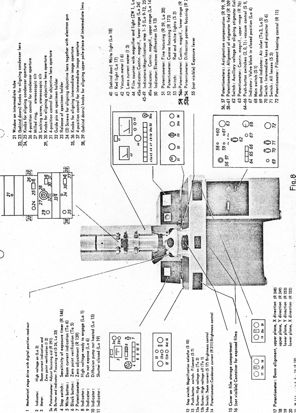
15 Diagram of Zeiss 9 Control Panels 15
16 16
17 17 Magnification steps on the Zeiss 9 The Zeiss 9 was calibrated on December 10, 1982 with a Pelco shadowed replica diffraction grating with 16,700 lines per centimeter. Magnification step Actual Magnification* minimum maximum average SD Step 1 1,810 1,830 1, Step 2 4,610 4,780 4, Step 3 7,540 8,210 7, Step 4 25,400 26,500 25, Step 5 58,300 59,400 58, Variable magnification ranges: Projector lens current setting at X 2,000 gives magnifications from X 1,893 to X 1,965, average X 1,940 with SD of Recommendation: Turn up your magnification to step 3 for 10 seconds or so prior to setting your desired magnification. Magnification then is (average) X 1,957 with SD 8.1. Intermediate lens current setting at X 20,000 gives magnification of 19,120. Any extrapolations based on this data are at your own risk! Please coordinate any of your own attempts to calibrate the scope with the EML. *These measurements vary because of hysteresis. The lower values were obtained by increasing magnification to the step shown. The higher values were obtained by decreasing magnification to the step shown.
18 18 Transmission Electron Microscopy Darkroom Policy In order to promote the most efficient and economical use of the TEM facilities, the following procedures should be followed: 1. Chemicals: Will be provided by the EML and are available upon request. All mixed chemicals should be fully labelled and list the date and person who mixed the chemical. All mixing of dry chemicals is to be conducted in the teaching lab or some other area outside of the EML where stray chemical dust will not harm equipment or photographic materials. Fixer: Use until exhausted (Use Hypo Check). Store in developing tank under the sink. Developer D-19: is to be mixed in a 1:2 ratio with water and is to be stored ready for use in a plastic container. Diluted D-19 and stock (full strength) D-19 should be fully labelled and dated. Empty developing tank after use. Discard diluted D- 19 after two months or 500 negatives. Photo Flo: Mix prior to each use and discard after use. (Keeping old solutions can result in severe fungal contamination.) Nitrogen: The nitrogen burst system should be turned on immediately before developing and turned off immediately following developing. Following use, pressure in the supply hose should be released by turning the burst control onto "continuous" for several minutes after shutting off the nitrogen supply. 2. Film: Will be provided by the EML and is available upon request. The EML is free to request reimbursement by users, depending on film usage and the user's resources. Film for the Zeiss 9 will be located in the dessicator cannister in the corner of the room housing the Zeiss 9. Film for the Zeiss 10 will be located in the built-in film dessicator. At least 50 negatives should be in the dessicator at all times. All extra film holders available after filling the microscope camera, if any, should be returned to the dessicator, filled with film and pre-dessicated for immediate use in the microscope. 3. Changing the camera: If at the end of a user's session, 10 or more film sheets have been exposed, it is the responsibility of that user to replace the film and to develop the exposed sheets (whether the sheets belong to the current user or not). Any exposed film left in the microscope after a user's session is left at the owner's risk. The EML will accept no responsibility for poor development of exposed film left in the microscope. 4. Photographic printing facilities: Negatives may be printed in the EML in a darkroom located in the EML building. Facilities include a Durst enlarger and ancillary equipment. Paper and chemicals provided by the EML are to be used only for coursework; continuing users must provide their own developing supplies. 5. Cleaning up: All darkroom areas are to be kept clean at all times. Removal of chemical stains requires large amounts of water. Sprayer hoses provided in each of the darkrooms should facilitate this.
19 GENERAL MICROSCOPE OPERATION 19
20 TAKING ELECTRONMICROGRAPHS 20
21 21
22 OPERATING THE VACUUM DESSICATOR 22
Operating the Hitachi 7100 Transmission Electron Microscope Electron Microscopy Core, University of Utah
 Operating the Hitachi 7100 Transmission Electron Microscope Electron Microscopy Core, University of Utah Follow the procedures below when you use the Hitachi 7100 TEM. Starting Session 1. Turn on the cold
Please follow these instructions for use of the Philips CM100 TEM. Adopted from website below.
 Please follow these instructions for use of the Philips CM100 TEM. Adopted from website below. http://staff.washington.edu/wpchan/if/cm100_inst.shtml Instructions for the Philips CM100 TEM and peripherals
2 How to operate the microscope/obtain an image
 Morgagni Operating Instructions 50079 010912 2-1 2 ow to operate the microscope/obtain an image 2.1 Starting the microscope 2.1.1 Starting the microscope with several manually-operated steps 1. Turn on
JEOL JEM-1400 Transmission Electron Microscope Operating Instructions
 JEOL JEM-1400 Transmission Electron Microscope Operating Instructions Anti-contamination device Objective aperture Objective aperture translation knobs Specimen holder Pump/air switch Left hand control
OPERATION OF THE HITACHI S-450 SCANNING ELECTRON MICROSCOPE. by Doug Bray Department of Biological Sciences University of Lethbridge
 OPERATION OF THE HITACHI S-450 SCANNING ELECTRON MICROSCOPE by Doug Bray Department of Biological Sciences University of Lethbridge Revised September, 2000 Note: The terms in bold in this document represent
Basic Users Manual for Tecnai-F20 TEM
 Basic Users Manual for Tecnai-F20 TEM NB: This document contains my personal notes on the operating procedure of the Tecnai F20 and may be used as a rough guide for those new to the microscope. It may
MSE 460 TEM Lab 2: Basic Alignment and Operation of Microscope
 MSE 460 TEM Lab 2: Basic Alignment and Operation of Microscope Last updated on 1/8/2018 Jinsong Wu, jinsong-wu@northwestern.edu Aims: The aim of this lab is to familiarize you with basic TEM alignment
Procedures for Performing Cryoelectron Microscopy on the FEI Sphera Microscope
 Procedures for Performing Cryoelectron Microscopy on the FEI Sphera Microscope The procedures given below were written specifically for the FEI Tecnai G 2 Sphera microscope. Modifications will need to
Instructions for Tecnai a brief start up manual
 Instructions for Tecnai a brief start up manual Version 3.0, 8.12.2015 Manual of Tecnai 12 transmission electron microscope located at Aalto University's Nanomicroscopy Center. More information of Nanomicroscopy
1. Specimen Holder Removal, Loading, and Insertion
 OPERATION OF THE PHILIPS CM-200 FEG-TEM When not in use, the CM-200 should be in the MICROSCOPE ON configuration with the HIGH TENSION ON (illuminates green when the high tension is on).. The microscope
User Operation of JEOL 1200 EX II
 **Log onto Computer** Open item program Start Up Procedure User Operation of JEOL 1200 EX II 1. If scope is not running, locate an electron microscopy technician (EMT) to find out why not. 2. Turn up brightness
1.3. Before loading the holder into the TEM, make sure the X tilt is set to zero and the goniometer locked in place (this will make loading easier).
.") JEOL 200CX operating procedure Nicholas G. Rudawski ngr@ufl.edu (805) 252-4916 1. Specimen loading 1.1. Unlock the TUMI system. 1.2. Load specimen(s) into the holder. If using the double tilt holder, ensure
JEOL 200CX operating procedure Nicholas G. Rudawski ngr@ufl.edu (805) 252-4916 1. Specimen loading 1.1. Unlock the TUMI system. 1.2. Load specimen(s) into the holder. If using the double tilt holder, ensure
Operating Checklist for using the Scanning Electron Microscope, JEOL JSM 6400.
 Smith College August 2005 Operating Checklist for using the Scanning Electron Microscope, JEOL JSM 6400. CONTENT, page no. Pre-Check, 1 Specimen Insertion, 1 Startup, 2 Filament Saturation, 2 Beam Alignment,
Operating Checklist for using the Scanning Electron. Microscope, JEOL JSM 6400.
 Smith College August 2009 Operating Checklist for using the Scanning Electron Microscope, JEOL JSM 6400. CONTENT, page no. Pre-Check 1 Startup 1 Specimen Insertion 2 Filament Saturation 2 Beam Alignment
1.2. Make sure the viewing screen is covered (exposure to liquid N 2 may cause it to crack).
.") FEI Tecnai F20 S/TEM: imaging in TEM mode Nicholas G. Rudawski ngr@ufl.edu (805) 252-4916 (352) 392-3077 Last updated: 01/21/18 1. Filling the cold trap (if needed) 1.1. Prior to use, the cold trap needs
FEI Tecnai F20 S/TEM: imaging in TEM mode Nicholas G. Rudawski ngr@ufl.edu (805) 252-4916 (352) 392-3077 Last updated: 01/21/18 1. Filling the cold trap (if needed) 1.1. Prior to use, the cold trap needs
MSE 595T Transmission Electron Microscopy. Laboratory III TEM Imaging - I
 MSE 595T Basic Transmission Electron Microscopy TEM Imaging - I Purpose The purpose of this lab is to: 1. Make fine adjustments to the microscope alignment 2. Obtain a diffraction pattern 3. Obtain an
Standard Operating Procedure for the Amray 1810 Scanning Electron Microscope Version: 29 NOVEMBER 2014
 Standard Operating Procedure for the Amray 1810 Scanning Electron Microscope Version: 29 NOVEMBER 2014 1. Utility Requirements a. System power is supplied by two 120 VAC/20 A circuits. When doing maintenance
FEI Tecnai G 2 F20 Operating Procedures
 FEI Tecnai G 2 F20 Operating Procedures 1. Startup (1) Sign-up in the microscope log-sheet. Please ensure you have written an account number for billing. (2) Log in to the computer: Login to your account
CALIBRATION OF MICROSCOPE EYEPIECE GRATICULE
 CALIBRATION OF MICROSCOPE EYEPIECE GRATICULE A typical eyepiece graticule looks like this: It is 10mm in length and each mm is divided into 10 parts So each small division = 0.1mm = 100µm The eyepiece
ILFORD SPORTSVIEW PROJECTOR INSTRUCTION BOOK
 ILFORD SPORTSVIEW PROJECTOR INSTRUCTION BOOK Now that you're the owner of a new Sportsview Projector, you'll want to begin using it right away. The Sportsview Projector is extremely simple to operate,
2. Raise HT to 200kVby following the procedure explained in 1.6.
 JEOL 2100 MANUAL Quick check list 1. If needed, fill the reservoir with LN2 2. Raise HT to 200kVby following the procedure explained in 1.6. 3. Insert specimen holder into TEM (Insert holder in airlock,
Introduction: Why electrons?
 Introduction: Why electrons? 1 Radiations Visible light X-rays Electrons Neutrons Advantages Not very damaging Easily focused Eye wonderful detector Small wavelength (Angstroms) Good penetration Small
PRINTING SETUP with OMEGA ENLARGER
 PRINTING SETUP with OMEGA ENLARGER Follow this procedure when beginning a work session in the Darkroom. Use this page as an actual checklist as you prepare to work. Get a key from the Monitor in the Cage
Full-screen mode Popup controls. Overview of the microscope user interface, TEM User Interface and TIA on the left and EDS on the right
 Quick Guide to Operating FEI Titan Themis G2 200 (S)TEM: TEM mode Susheng Tan Nanoscale Fabrication and Characterization Facility, University of Pittsburgh Office: M104/B01 Benedum Hall, 412-383-5978,
User instructions Compound laboratory microscope
 KERN & Sohn GmbH Ziegelei 1 D-72336 Balingen E-mail: info@kern-sohn.com User instructions Compound laboratory microscope Tel: +49-[0]7433-9933-0 Fax: +49-[0]7433-9933-149 Internet: www.kern-sohn.com KERN
Therefore, all descriptions and illustrations in this instruction manual, including all specifications are subject to change without notice.
 We are constantly endeavouring to improve our instruments and to adapt them to the requirements of modern research techniques and testing methods. This involves modification to the mechanical structure
S200 Course LECTURE 1 TEM
 S200 Course LECTURE 1 TEM Development of Electron Microscopy 1897 Discovery of the electron (J.J. Thompson) 1924 Particle and wave theory (L. de Broglie) 1926 Electromagnetic Lens (H. Busch) 1932 Construction
Title: Amray 1830 SEM#2 Semiconductor & Microsystems Fabrication Laboratory Revision: D Rev Date: 03/18/2016
 Approved by: Process Engineer / / / / Equipment Engineer 1 SCOPE The purpose of this document is to detail the use of the Amray 1830 SEM. All users are expected to have read and understood this document.
HOLOGRAPHY EXPERIMENT 25. Equipment List:-
 EXPERIMENT 25 HOLOGRAPHY Equipment List:- (a) (b) (c) (d) (e) (f) (g) Holography camera and plate holders Laser/beam lamp and assembly Shutter on stand Light meter Objects to make holographs of Holographic
LEO 912 TEM Short Manual. Prepared/copyrighted by RH Berg Danforth Plant Science Center
 LEO 912 TEM Short Manual Prepared/copyrighted by RH Berg Danforth Plant Science Center Specimen holder [1] Never touch the holder (outside of the O-ring, double-headed arrow) because finger oils will contaminate
CAPTURING IMAGES ON THE HIGH-MAGNIFICATION MICROSCOPE
 University of Virginia ITC Academic Computing Health Sciences CAPTURING IMAGES ON THE HIGH-MAGNIFICATION MICROSCOPE Introduction The Olympus BH-2 microscope in ACHS s microscope lab has objectives from
1.1. In regular TEM imaging mode, find a region of interest and set it at eucentric height.
 JEOL 2010F operating procedure Covers operation in STEM mode (See separate procedures for operation in TEM mode and operation of EDS system) Nicholas G. Rudawski ngr@ufl.edu (805) 252-4916 NOTE: this operating
Instruction Manual T Binocular Acromat Research Scope T Trinocular Acromat Research Scope
 Research Scope Instruction Manual T-29031 Binocular Acromat Research Scope T-29041 Trinocular Acromat Research Scope T-29032 Binocular Semi-Plan Research Scope T-29042 Trinocular Semi-Plan Research Scope
User instructions Compound laboratory microscope
 KERN & Sohn GmbH Ziegelei 1 D-72336 Balingen E-mail: info@kern-sohn.com User instructions Compound laboratory microscope Tel: +49-[0]7433-9933-0 Fax: +49-[0]7433-9933-149 Internet: www.kern-sohn.com KERN
How to use the Jeol 1010 TEM of GI (Liesbeth own GI version)
") How to use the Jeol 1010 TEM of GI (Liesbeth own GI version) 1.Load the specimen Load a grid into the rod holder: USE ONLY THE TOP POSITION (blue arrow), Specimen selection on 1 (The rear one is only a
How to use the Jeol 1010 TEM of GI (Liesbeth own GI version) 1.Load the specimen Load a grid into the rod holder: USE ONLY THE TOP POSITION (blue arrow), Specimen selection on 1 (The rear one is only a
05/20/14 1. Philips CM200T. Standby Condition
 05/20/14 1 Philips CM200T Standby Condition HT and filament off, HT setting at 200kV. RESET HOLDER, center sample tilt knobs, and remove sample. Mag ~ 5-10kX Objective and SA apertures out, C2 aperture
Section 1: TEM parts and functions... 2
 Introduction The set of instructions below are written by Charlie Sanabria within the first few sessions of his TEM training process, and are intended for anyone interested in viewing the TEM operation
SEM OPERATION IN LOW VACUUM MODE
 SEM OPERATION IN LOW VACUUM MODE Instructions for JEOL 5800 LV The EVAC light of the SEM specimen chamber should be already lit when you approach the SEM & the SEM will have been left in the high vacuum
Manual for BMS E1 eplan series, compound microscope
 Manual for BMS E1 eplan series, compound microscope The compound microscope allows it to study, at cell level, structures of textures of botanical and zoological nature. (e.g. slides of roots, leaves and
Basic Microscopy. OBJECTIVES After completing this exercise, you should be able to do the following:
 Page 1 of 10 Basic Microscopy OBJECTIVES After completing this exercise, you should be able to do the following: a. Name the parts of the compound microscope and the functions of each. b. Describe how
Nuclear Associates
 Nuclear Associates 07-424 Digital Densitometer II Operators Manual March 2005 Manual No. 112111 Rev. 4 2003, 2005 Fluke Corporation, All rights reserved. Printed U.S.A. All product names are trademarks
Using a Microscope. Year Group: BVSc1 + Document number: CSL_L07
 Year Group: BVSc1 + Document number: CSL_L07 Equipment list: Equipment for this station: Microscope Power supply and a level surface to work on Gloves The sample to examine Marker or pencil for labelling
Basic Microscopy for Plant Biology
 Page 1 of 8 Basic Microscopy for Plant Biology OBJECTIVES After completing this exercise, you should be able to do the following: a. Name the parts of the compound microscope and the functions of each.
STANDARD OPERATING PROCEDURE: JEOL TEM-2100
 STANDARD OPERATING PROCEDURE: JEOL TEM-2100 Purpose of this Instrument: Essential tool for structural characterization of natural or synthesized nanostructures. Location: WVU - Engineering Sciences Building
Match the microscope structures given in the left column with the statements in the right column that identify or describe them.
 49 Prelab for Name Match the microscope structures given in the left column with the statements in the right column that identify or describe them. Key: a. coarse adjustment knob f. turret or nosepiece
ML7520 ML7530 DIOPTER ADJUSTMENT RING BINOCULAR BODY, INCLINED 30. (a) Field Iris Control Lever. (c) Filter Slots EYEPIECES, KHW10X
 Field Iris Control Lever. (c) Filter Slots EYEPIECES, KHW10X") JAPAN DIOPTER ADJUSTMENT RING BINOCULAR BODY, INCLINED 30 (a) Field Iris Control Lever (c) Filter Slots EYEPIECES, KHW10X ANALYZER CONTROL LEVER (b) Aperture Iris Control Lever LIGHT SOURCE HOUSING VERTICAL
JAPAN DIOPTER ADJUSTMENT RING BINOCULAR BODY, INCLINED 30 (a) Field Iris Control Lever (c) Filter Slots EYEPIECES, KHW10X ANALYZER CONTROL LEVER (b) Aperture Iris Control Lever LIGHT SOURCE HOUSING VERTICAL
Chapter 2 Alignment C. Robert Bagnell, Jr., Ph.D., 2012
 Chapter 2 Alignment C. Robert Bagnell, Jr., Ph.D., 2012 Figure 2.1 is an image of striated muscle taken with a misaligned microscope and figure 2.2 is with a properly aligned microscope. To the untrained
SEM Training Notebook
 SEM Training Notebook Lab Manager: Dr. Perry Cheung MSE Fee-For-Service Facility Materials Science and Engineering University of California, Riverside December 21, 2017 (rev. 3.4) 1 Before you begin Complete
Marine Invertebrate Zoology Microscope Introduction
 Marine Invertebrate Zoology Microscope Introduction Introduction A laboratory tool that has become almost synonymous with biology is the microscope. As an extension of your eyes, the microscope is one
SWIFT SERIES M2252DGL MICROSCOPE
 SWIFT SERIES M2252DGL MICROSCOPE The M2252DGL Series is ideal for elementary to high school classrooms. Built to withstand student use, this series has locked-on eyepieces, objectives, illuminator housing
JEOL 6500 User Manual
 LOG IN to your session on the computer to the left of the microscope. Starting Conditions 1. Press Ctrl-Alt-Del and log on to the microscope computer. Click on JEOL PC SEM 6500 icon. Click yes if message
BX-61: Brightfield Instruction /Continue to scroll for Fluorescent Instuctions
 BX-61: Brightfield Instruction /Continue to scroll for Fluorescent Instuctions Starting up: Schematic of Olympus BX-61. 1. Turn on Olympus microscope power box (left of microscope) with toggle switch on
JEOL JEM 2010 TRAINING TRANSMISSION ELECTRON MICROSCOPE USER MANUAL
 JEOL JEM 2010 TRAINING TRANSMISSION ELECTRON MICROSCOPE USER MANUAL Version 5.1 EM Facility CMSE-SEF Massachusetts Institution of Technology TABLE OF CONTENTS 1. Specifications...2 1.1 Performance...2
Eyepieces KHW10X. Diopter Adjustment Ring. Binocular Body Inclined 30. Binocular Clamp Screw. Analyzer control Lever. Reflected Light Illuminator
 JAPAN Eyepieces KHW10X Diopter Adjustment Ring Binocular Body Inclined 30 Binocular Clamp Screw Analyzer control Lever Reflected Light Illuminator Ball-Bearing Objective Nosepiece Objectives Large Scan
User Manual. Digital Compound Binocular LED Microscope. MicroscopeNet.com
 User Manual Digital Compound Binocular LED Microscope Model MD82ES10 MicroscopeNet.com Table of Contents i. Caution... 1 ii. Care and Maintenance... 2 1. Components Illustration... 3 2. Installation...
User instructions Metallurgical inverted microscope
 KERN & Sohn GmbH Ziegelei 1 D-72336 Balingen E-mail: info@kern-sohn.com Tel: +49-[0]7433-9933-0 Fax: +49-[0]7433-9933-149 Internet: www.kern-sohn.com User instructions Metallurgical inverted microscope
MSE 460 TEM Lab 4: Bright/Dark Field Imaging Operation
 MSE 460 TEM Lab 4: Bright/Dark Field Imaging Operation Last updated on 1/8/2018 Jinsong Wu, jinsong-wu@northwestern.edu Aims: The aim of this lab is to familiarize you with bright/dark field imaging operation.
RAITH e-line OPERATING INSTRUCTIONS
 RAITH e-line OPERATING INSTRUCTIONS 1) LOADING A SAMPLE a. Start the system i. On the Column PC (Right side monitor [R]), select the SmartSEM icon to on the desktop to begin the column software. ii. On
Basic Operating Instructions for Strata Dual Beam 235 FIB/SEM
 Basic Operating Instructions for Strata Dual Beam 235 FIB/SEM Warning Always adjust your specimen height before closing the chamber door to make sure your specimen will not hit the bottom of the lens;
This document assumes the user is already familiar with basic operation of the instrument in TEM mode and use of the Microscope Control interface.
 FEI Tecnai F20 S/TEM: imaging in STEM mode Nicholas G. Rudawski ngr@ufl.edu (805) 252-4916 (352) 392-3077 Last updated: 05/10/18 This document assumes the user is already familiar with basic operation
Materials Polishing Manual. By Thomas Perry Daniel Webster College Version 1 August 10, 2007
 Materials Polishing Manual By Thomas Perry Daniel Webster College Version 1 August 10, 2007 Materials Polishing Manual This manual describes how to use the equipment at Daniel Webster College to create
Transmission Electron Microscopy 9. The Instrument. Outline
 Transmission Electron Microscopy 9. The Instrument EMA 6518 Spring 2009 02/25/09 Outline The Illumination System The Objective Lens and Stage Forming Diffraction Patterns and Images Alignment and Stigmation
SEM Training Notebook
 SEM Training Notebook Lab Manager: Dr. Perry Cheung MSE Fee-For-Service Facility Materials Science and Engineering University of California, Riverside March 8, 2018 (rev. 3.5) 1 Before you begin Complete
JEOL 6700 User Manual 05/18/2009
 JEOL 6700 User Manual 05/18/2009 LOG IN to your session on the computer to the right of the microscope. Starting Conditions 1. Click the button and read the Penning Gauge to ensure that the microscope
Zoom Stereo Microscope NYMCS-360 Instruction Manual
 Zoom Stereo Microscope NYMCS-60 Instruction Manual This manual is written for stereo microscope NYMCS-60. To ensure the safety, obtain optimum performance and to familiarize yourself fully with the use
Biology 29 Cell Structure and Function Spring, 2009 Springer LABORATORY 1: THE LIGHT MICROSCOPE
 Biology 29 Cell Structure and Function Spring, 2009 Springer LABORATORY 1: THE LIGHT MICROSCOPE Prior to lab: 1) Read these instructions (p 1-6) 2) Go through the online tutorial, the microscopy pre-lab
Biological Microscope Manual
 Version No.: V1.2 Series Biological Microscope Manual This manual expatiates the using method, troubleshooting and maintenance about MT-50 series biological microscope. Please study this manual thoroughly
7878 K940. Checkpoint Antenna. Kit Instructions. Issue B
 7878 K940 Checkpoint Antenna Kit Instructions Issue B Revision Record Issue Date Remarks A July 7, 2009 First issue B Nov2013 Revised the Checkpoint installation procedures for 7878 and 7874 scanners Added
RIGAKU VariMax Dual Part 0 Startup & Shutdown Manual
 i RIGAKU VariMax Dual Part 0 Startup & Shutdown Manual X-ray Laboratory, Nano-Engineering Research Center, Institute of Engineering Innovation, School of Engineering, The University of Tokyo Figure 0:
WITec Alpha 300R Quick Operation Summary October 2018
 WITec Alpha 300R Quick Operation Summary October 2018 This document is frequently updated if you feel information should be added, please indicate that to the facility manager (currently Philip Carubia,
Nikon Ti-E Microscope Manual. Rightmire Hall Ohio State University. Director: Tony Brown Rightmire
 Nikon Ti-E Microscope Manual Rightmire Hall Ohio State University Director: Tony Brown Rightmire 060 292-1205 brown.2302@osu.edu Facility Manager: Paula Monsma Rightmire 062 293-0939 292-1367 monsma.1@osu.edu
Brightfield Microscopy and Image Acquisition on Spotcam1. by Ryan Taylor/Nancy Kleene Last modified 10/02/05 by Birgit Ehmer
 Brightfield Microscopy and Image Acquisition on Spotcam1 by Ryan Taylor/Nancy Kleene Last modified 10/02/05 by Birgit Ehmer Log onto the computer. Enter your username and password to log onto the server.
Repairing Microsoft Wedge Touch Mouse Battery Cover Retaining Clip
 Repairing Microsoft Wedge Touch Mouse Battery Cover Retaining Clip Disassembly, repair and reassembly of Wedge Touch mouse when the battery cover will not stay closed. Also is a good guide to repair other
Aperture: Circular hole in front of or within a lens that restricts the amount of light passing through the lens to the photographic material.
 Aperture: Circular hole in front of or within a lens that restricts the amount of light passing through the lens to the photographic material. Backlighting: When light is coming from behind the subject,
Processing and. Photography. Printing
 Processing and Photography Printing Darkroom Layout Divided into dry area and wet area Need good workflow between the two Dry bench consists of enlarger photographic paper multigrade filters contact printer
MICROSCOPE LAB. Resolving Power How well specimen detail is preserved during the magnifying process.
 AP BIOLOGY Cells ACTIVITY #2 MICROSCOPE LAB OBJECTIVES 1. Demonstrate proper care and use of a compound microscope. 2. Identify the parts of the microscope and describe the function of each part. 3. Compare
OM FL400. Reflected Light Fluorescence Microscope. Instruction Manual. Please read instructions carefully before using microscope.
 OM FL400 Reflected Light Fluorescence Microscope Instruction Manual Please read instructions carefully before using microscope. Contents Safety ---------------------------------------------- 2 Parts List
Basics of Light Microscopy and Metallography
 ENGR45: Introduction to Materials Spring 2012 Laboratory 8 Basics of Light Microscopy and Metallography In this exercise you will: gain familiarity with the proper use of a research-grade light microscope
Easy Kohler Illumination Method
 Easy Kohler Illumination Method ACADEMIC SKILLS CENTRE (ASC) A. Silverberg Completion of a Kohler illumination method is required before a microscope can be used efficiently. The Kohler method is designed
KODAK PROFESSIONAL T-MAX P3200 Black & White Negative Film
 KODAK PROFESSIONAL T-MAX P3200 Black & White Negative Film TECHNICAL DATA / BLACK-AND-WHITE FILM March 201 F-4001 KODAK PROFESSIONAL T-MAX P3200 Black & White Negative Film 3200TMZ is a multi-speed continuous-tone
Care and Use of the Compound Light Microscope
 EXERCISE 2 Care and Use of the Compound Light Microscope Time Estimates for Completing This Lab The activities in this laboratory exercise can be completed in 2 to 2.5 hours. Extra time will be required
The wick in your heater needs replacing if, after repeated cleanings, any of the following conditions still exist:
 WICK REPLACEMENT The wick in your heater needs replacing if, after repeated cleanings, any of the following conditions still exist: Slow to light, hard movement of the wick adjuster knob, kerosene odor
LASER ENHANCED REVOLVER GRIP OWNER S MANUAL RED LASER GREEN LASER
 LASER ENHANCED RED LASER GREEN LASER REVOLVER GRIP OWNER S MANUAL LASER ENHANCED GRIP Installation Instructions Caution... 3 Safety Labels... 4 Installation...5-7 Programming...8-10 Batteries (Red Laser)...
INSTRUCTION MANUAL. Force Transducer Output Tube Repair Kit
 INSTRUCTION MANUAL Model 400-TR Force Transducer Output Tube Repair Kit June 4, 2004, Revision 5 Copyright 2004 Aurora Scientific Inc. Aurora Scientific Inc. 360 Industrial Pkwy. S., Unit 4 Aurora, Ontario,
P20 Zoom Flash Zoom Flash P20 P20 Zoomblitz Flash con zoom P20 Flash externo P20 Flash Zoom P20
 P20 Zoom Flash Zoom Flash P20 P20 Zoomblitz Flash con zoom P20 Flash externo P20 Flash Zoom P20 User s Guide Guide d'utilisation Benutzerhandbuch Manuale per l'utente Guía del usuario Guia do usuário 4J6021
UNIVERSITY OF WATERLOO Physics 360/460 Experiment #2 ATOMIC FORCE MICROSCOPY
 UNIVERSITY OF WATERLOO Physics 360/460 Experiment #2 ATOMIC FORCE MICROSCOPY References: http://virlab.virginia.edu/vl/home.htm (University of Virginia virtual lab. Click on the AFM link) An atomic force
INSTALLATION GUIDE 2009-CURRENT HUMMER H3T PRODUCT CODE:
 INSTALLATION GUIDE 2009-CURRENT HUMMER H3T PRODUCT CODE: 268 June 22, 2010 TOOLS NEEDED COMPONENTS INCLUDED P2 Tip 3/8" Drill Rubber Gasket(s) x 2 Bracket(s) x 2 1/2" Drill Bit Bulkhead Flange #2 Phillips
KODAK PROFESSIONAL T-MAX P3200 Black & White Negative Film
 KODAK PROFESSIONAL T-MAX P3200 Black & White Negative Film TECHNICAL DATA / BLACK-AND-WHITE FILM July 201 F-4001 KODAK PROFESSIONAL T-MAX P3200 Black & White Negative Film 3200TMZ is a multi-speed continuous-tone
User instructions Biological inverted microscope
 KERN & Sohn GmbH Ziegelei 1 D-72336 Balingen E-mail: info@kern-sohn.com User instructions Biological inverted microscope Tel: +49-[0]7433-9933-0 Fax: +49-[0]7433-9933-149 Internet: www.kern-sohn.com KERN
Ribcage Installation. Part 2 - Assembly. Back-Bone V1.06
 Ribcage Installation Part 2 - Assembly Back-Bone V1.06 Contents Section 1 Before You Get Started... 2 Included With Your Kit:... 2 Figure: A... 3 CAUTION!... 4 Note:... 4 Tools Required... 5 Section 2:
STEINBERGER TRANSTREM (TYPE 2) TECHNICAL DOCUMENT
 TECHNICAL DOCUMENT") STEINBERGER TRANSTREM (TYPE 2) TECHNICAL DOCUMENT These instructions apply to newer style TransTrems only (non-threaded ball type or modified threaded ball type). For purposes of discussion, these TransTrems
STEINBERGER TRANSTREM (TYPE 2) TECHNICAL DOCUMENT These instructions apply to newer style TransTrems only (non-threaded ball type or modified threaded ball type). For purposes of discussion, these TransTrems
STEINDORFF NYMC C. Comparison Microscope. Operating Instructions. A. Features and Functions
 1 NYMC0035000C Comparison Microscope Operating Instructions A. Features and Functions Through optical enlargement, this comparison microscope, can help the user to observe clearly, by looking into the
Dickinson College Department of Geology
 Dickinson College Department of Geology Title: Equipment: BASIC OPERATION OF THE SCANNING ELECTRON MICROSCOPE (SEM) JEOL JSM-5900 SCANNING ELECTRON MICROSCOPE Revision: 2.2 Effective Date: 1/29/2003 Author(s):
FE-SEM SU-8020 Operating manual (Preliminary version)
") FE-SEM SU-8020 Operating manual (Preliminary version) 2016/04/11 Seimitsu Bunseki sitsu lab. Starting up 1.Turn on the Display switch. Windows OS is starting up 2. Select the user SU-8000. 3. Click the
FE-SEM SU-8020 Operating manual (Preliminary version) 2016/04/11 Seimitsu Bunseki sitsu lab. Starting up 1.Turn on the Display switch. Windows OS is starting up 2. Select the user SU-8000. 3. Click the
Cut-True 16M Manual Paper Cutter
 Cut-True 16M Manual Paper Cutter 2/2013 OPERATOR MANUAL FIRST EDITION TABLE OF CONTENTS TOPIC PAGE Specifications 1 Safety Guidelines 1 Assembly 2 Overview 3 Description of Equipment Parts 3-4 Operation
Using a Compound Light Microscope
 Name Class Date Laboratory Skills 5 Using a Compound Light Microscope Introduction Many objects are too small to be seen by the eye alone. They can be seen, however, with the use of an instrument that
Rachel
 http://gmv.cast.uark.edu A Method Store for Advanced Survey and Modeling Technologies Mon, 01 Apr 2013 03:29:18 +0000 en-us hourly 1 http://wordpress.org/?v=3.5.1 http://gmv.cast.uark.edu/scanning/guide-to-leveling-andaligning-the-breuckmann-tripod-and-smartscan-he-for-calibration/
DEVELOPMENT. The following developers are recommended: Ilford ID-2 Developer For Fine Grain Safety Positive Film.
 DEVELOPMENT The following developers are recommended: Ilford ID-2 Developer For Fine Grain Safety Positive Film. Ilford ID-20 Developer For Bromide Paper. Both these developers may be obtained as packed
Zeiss LSM 880 Protocol
 Zeiss LSM 880 Protocol 1) System Startup Please note put sign-up policy. You must inform the facility at least 24 hours beforehand if you can t come; otherwise, you will receive a charge for unused time.
Tecnai T12 Operating Procedures
 Tecnai T12 Operating Procedures I. Initial Procedures 1 II. Accelerating Voltage 3 III. Specimen Loading and Holder Insertion/Removal 3 IV. Emission Current 7 V. Alignment 7 VI. Camera Control and Imaging