Handbook for the Starlight Xpress AOLF unit Issue 3 17/8/2015. Handbook for the Starlight Xpress SXV-AOLF unit (version 2)
|
|
|
- Marsha Sparks
- 6 years ago
- Views:
Transcription

1 Handbook for the Starlight Xpress SXV-AOLF unit (version 2) Thank you for purchasing an SXV-AOLF2 active optics unit. This device should give you much improved guiding accuracy with almost any telescope and mount. Please read the following manual which will explain how the device operates and the best ways in which it can be applied to your optical system. The AOLF2 is an updated and improved version of the AOLF unit that was launched in It adds an internal USB to serial converter, so that a direct USB connection may be used, and the stepper motor drivers have increased torque capability to reduce the chances of mechanical jamming.

2 The principle of operation: The SXV-AOLF2 device provides an effective method of removing the effects of rapid guiding errors from CCD images. All but the most expensive telescope mounts suffer from rapid gear errors during guiding and such errors are very difficult to correct when the only control method available is to send speed corrections to the drive motors. A device which can adjust the image position by rapidly deviating the optical path, can correct for such errors very quickly and without the associated settling time issues. The most common method of shifting an image for AO purposes is to use a tip-tilt mirror to reflect the beam through a variable angle. This works well, but deviates the optical path through 90 degrees and takes up a considerable back focal distance. Its motion sensitivity is also affected by the distance between the mirror and the CCD. A straight though device is more convenient and optically shorter, so the SX unit was designed with this in mind. A secondary advantage of the straight through design is that it is possible to construct a system that has a well defined optical deviation for a defined input signal. This means that the sensitivity of the system in pixels shift per input step is essentially constant and is independent of the optical system used and the distance between the CCD and AO. The AO element is a Multi-coated AR bloomed plane-parallel optical window with a thickness of 13mm and a diameter of 60mm. This element can be tilted by up to approximately +/- 3 degrees, by rotating four small stepper motors at the periphery of the aluminium carrier plate. Converging light from the telescope objective lens or mirror, passes through the window on its way to the CCD chip, but is essentially unaffected when the window is perpendicular to the beam. However, when the window is tilted, the converging beam is displaced by an amount which can be defined as approximately
3 0.075mm per 1 degree of tilt. The maximum image deviation is therefore approximately +/- 0.15mm in both the X and Y planes. This corresponds to about +/- 23 pixels on the CCD of an SXV-H9 camera. The AO unit is usually controlled by serial data from an RS232 port. This port can be one of those provided on many PCs, or the serial interface of an SXV camera (if supported by the software package in use). A USB to serial adaptor can also be used on a PC without native serial ports. The serial data input of the AO is an RJ11 socket and so a lead with an RJ11 to 9 pin D style socket is provided to enable connection to a standard serial port. The computer port should be set to 9600B, 8 bits data, 1 stop bit, no parity. A typical application of the AO unit for off-axis guiding: The following diagram shows how the AO unit may be used with the optional off-axis guider (OAG) and an SX CCD camera. This is likely to be the normal configuration for most imagers, as it offers accurate guiding which is free of flexure and mirror shift problems. The OAG consists of a short aluminium barrel with a pick-off prism which feeds light to a Lodestar or SXV guide camera, mounted at the end of a short extension tube. The guide camera position is designed to be close to the correct focal distance when a Starlight Xpress camera is mounted on the main optical output of the OAG and brought into focus. Any small errors may be corrected by loosening the set screws in the threaded collar and sliding the camera into the correct position. The OAG is attached to the AO unit by three set screws which engage with a grooved ring at the output of the AO assembly. Please note that the guider barrel should be oriented so that it projects along the line which joins the North and South motors. When located properly, the two RJ11 sockets on the AO will be at the bottom of the unit, diametrically opposite to the guider barrel. The long axis of the CCD in the guide camera should be oriented so that it is parallel to the AO backplate. This can be seen in the picture at the front of this handbook, as indicated by the orientation of the guide camera socket.
4 The imaging camera is attached to the rear of the OAG, using a suitable adaptor ring. Two types are supplied one with a T thread for the SXV-H9/9C and M25C and one with an M72 thread for the H35 and 36. The orientation of the camera is adjusted by loosening the three set screws and rotating the ring into the required position. As the camera is not involved with collecting guiding information, it may be set at any angle. However, the pick off prism may cause shadowing if the long axis of a large chip is set in the vertical plane. Both the AO unit and the OAG have recesses which will take a 48mm filter. When using the OAG, it is an advantage to use the recess inside the camera mounting ring, so that the guide camera sensitivity is not compromised by any filters that you may add. This is
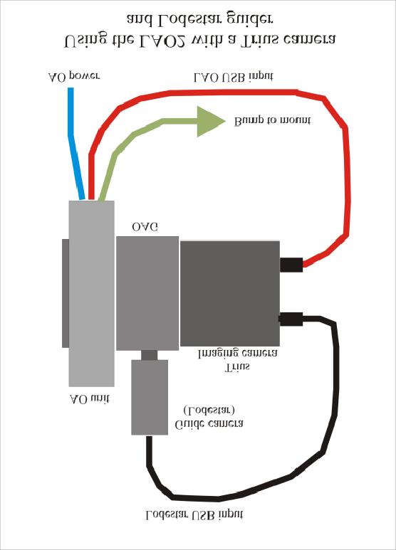
5 especially useful if you image with narrow band filters, such as H-alpha. A light pollution rejection filter, such as an IDAS P1 or P2 might be best added at the output of the AO unit (before the OAG), where it will improve the guide star contrast, as well as improving your camera images. Note that the recesses are not threaded and so you should be careful that a filter does not fall out and get damaged when dismantling the unit. Connecting up the AO electronics for guiding with a Lodestar or Superstar guider: The LAO version 2 has an additional input port in the form of a USB type B socket. This emulates an external USB to serial converter and so you do not need an additional converter with version 2. Just connect a USB cable from your computer and the LAO will be recognised as an FTDI serial device. Most versions of Windows will include FTDI drivers, but they can be downloaded from the FTDI web site, if required. You can still use the serial input of the AO unit, if this is preferred, but this socket is no longer needed for most systems. Both the USB and the serial socket work with the current software, as both will show up as serial COM ports on your computer. 1) Connect the USB cable (supplied) into the AO unit USB input socket. If you have a Trius camera, then this can be connected to one of the USB ports on the camera. Alternatively, connect it to a USB socket on your computer. 2) Connect the RJ11 to guider port cable (supplied) from the AO output to the guider input on the mount. This cable is not essential, but it allows the software to bump the mount when the errors become too large for the AO unit. Most lowercost mount users will find it necessary for long exposure times. 3) Connect the Lodestar or Superstar guide camera to the USB socket on the PC, or on the back of your Trius camera. 4) Connect the AO power lead to the power supply block. This basic configuration is suitable for use with third party imaging cameras. Most software does require the use of an SX guide camera, but the imaging camera can be almost any type, as it is not involved with control of the AO unit. Some cameras, such as the QSI range, often come with a built-in OAG assembly, and we can supply the LAO2 unit without an OAG, for use with such cameras. This reduces the cost somewhat. You can also use a similar configuration if you have an SX Mini-wheel or a standard wheel with a slim OAG attached. Here is a general diagram of the AO attached to a slim OAG + wheel:

6 The following drawings indicate some of the options for connecting the LAO2 to the guide camera and computer. The first one will be the most commonly used configuration, if you have a Lodestar and Trius series camera.
7


8 Owners of older SXV cameras might use the following option.
 will not operate the AO unless an SX guide camera is used.")
9 Operating the LAO2 with a Lodestar, Lodestar X2 or Superstar USB2 guide camera: The SX Lodestar or Superstar guide cameras may be used to control the AO unit, especially if you wish to use a third party imaging camera. Many other guiders are too large to fit and some software (e.g. Maxim DL) will not operate the AO unless an SX guide camera is used. It is best to use USB control of the LAO unit, as shown, and you can use PHD2 software to provide the LAO guiding corrections. Alternatively, AstroArt or MaximDL may be used for both guider and main camera control. General pointers: When the AO unit is first attached to the telescope, it is best to arrange the off-axis guide camera, so that the East West AO axis is parallel to the long axis of the guide image. This is easily done by viewing the guider or camera chip through the front of the AO window. Hold the AO unit so that the two RJ11 sockets are at the bottom and ensure that the guider chip is visible as a horizontal rectangle as seen in the off-axis prism.
10 The SXV-AO can execute an image position correction in a few milliseconds, but the effective correction rate is limited by the brightness of the guide star and the download speed of the guide camera image. For best results with a poor telescope mount, you need to choose as bright a star as possible and use a small guide window. Binning the guide camera image will also help. The orientation of the AO assembly is normally arranged so that the East-West RA drift direction is along the long axis of the guider chip. However, there is no reason to conform to this, if the mount corrections can cope with the non-standard orientation. In this case, you can rotate the entire unit about the optical axis for optimising the image orientation or for finding a suitable guide star, but you will need to calibrate the system for each change of angle. When attaching the AO unit to a T thread adaptor, be careful to ensure that the male thread does not project deeply into the AO body. Any projection can interfere with the movement of the image displacer and may jam the unit. If the thread is too long, add a card or plastic washer between the adaptor and AO front plate. During extreme movement of the displacer, the motors may encounter excessive friction and fail to start. The Calibrate command will normally overcome this, as it switches to a much lower speed, high-torque stepping rate after 5 seconds of failure to move. However, in the worst case, you can rotate the motors manually by inserting a small screwdriver through the holes in the front plate. Be careful not to rotate them too far, as only 4 turns is required to move the drive through its entire range. Adjust each motor until its shaft rotates as freely as possible before using the centre command again. Our AO Utility has an unjam option called Recovery and this might be useful if the jam will not free when using Calibrate Using the AO system: The following instructions are based on the software provided by Starlight Xpress and will be different for other control programs. Please read the relevant help files if you are using AstroArt or Maxim DL. I also assume that you are using the off-axis guider and serial control of the AO. All SX camera software includes an option to use the AO unit. You do not need extra software to operate the AO, if you already have an SX camera installed. Open the camera software and check that it recognises the presence of your main camera. Now open the Set program defaults menu (under File ) and check that the serial control settings are appropriate to your system. For instance, if you are using a serial port on the PC to drive the AO unit, check the AO unit available check box and then set the PC COM port number. The Select half rate box is to slow down the mount corrections that will occur if the AO unit exceeds its useful range. You may find this useful if you have a mount with rather erratic drives, such as an SCT on a fork mount. Now save the program defaults and return to the main program window.
11 Select the main camera icon (4 from the left) and use a short exposure time to see if there are any stars visible. Adjust the main telescope focus until you have a well focused star field in the main camera image. Now click on the Autoguider icon (5 from the left) and you will see the guider window and control panel. Select a 1 second exposure time and move the Stretch image slider to Maximum. Press the Start button and you should see a guide camera image appear in the image window. At this point, there may be no stars visible, as the guider focusing might be seriously in error. If no stars are seen, try increasing the guide exposure to 3 or more seconds until you can detect some stars. Now use the Allen key provided to loosen the two set screws in the guider retaining collar and then gently slide the guider backwards and forwards until a sharp star image is seen. Note that the image might be distorted by the telescope optics, as it is well off axis. Once focused, re-lock the collar in place, making sure that the guide camera orientation is with the input plug parallel to the AO backplate. Briefly blip one of the RA buttons on your telescope handset and ensure that the stars drift parallel to the long axis of the guider window if not, rotate the entire AO assembly about the telescope axis until they do so. Now check that the AO mode is set for serial and make sure that you have selected the correct AO control port if you are using the splitter box (ser1 or ser2). Press the Use default to temporarily set the guiding speed of the AO. You now have the system ready to test, so proceed as follows: Find an interesting object or starfield to image and adjust the scope until a convenient guide star can be seen in the guider field. Ideally, the star should be easily seen in an exposure of only 0.1 seconds and, if necessary, binning may be used to gain sensitivity. Once the guide star is identified, press the Centralise AO button and watch the star image it should cycle through a cross shaped figure and then settle after about 2 seconds. Now press Select guide star and click on the star which you think best suited to act as your guide reference (bright and isolated). You can now press the Train button and the AO will cycle automatically while measuring the system sensitivity. If the training cycle is successful, new rate values will be generated, although they will probably be much the same as the default values. If the calibration fails, it will probably be due to one or both of the AO direction settings being wrong. The defaults in the software are for a guide camera mounted as shown in the frontispiece picture of the AO assembly, with its indicator LED towards the camera end of the AO barrel. You can either rotate the guide camera to this position, or try swapping the AO up/down and left/right check box settings. Once you have the directions set and the motion rates determined, calibration of the AO will not be necessary in future sessions as it is a constant factor for all scopes. Only one other setting is still necessary. This is the calibration of the mount for mount bumps during your guiding session. Although the AO can take care of the small and rapid guiding errors, there will be steady drifts of the telescope drive which will slowly shift the AO to the limits of its motion range. To combat this effect, we need to send occasional corrections to the mount ( bumps ) in order that the AO remains near to the centre of its operating range. A relatively easy way in which to determine the settings required is to set the AO guiding on your selected
12 guide star (press Start guiding ) and then use the hand controller to move the star slightly East or West until the data boxes on the guider image start to show offset values of more than 50 steps. At this point you will see the text Move mount appear, along with a direction indication. If the result is that the AO error falls rapidly below 50 steps, then the mount direction and rate is about right, but any sign that the error is rapidly increasing will show that the Swap e/w or n/s direction is incorrect. Stop the guiding, reverse the Swap box for that direction and try guiding again. Once you have both directions set correctly, you can experiment with the mount speed (pixels per second) settings to optimise the amount of correction applied ideally you want the mount correction to move the AO back to the zero offset position, but there is a large tolerance on this. You are now ready to take an AO guided image. Re-centralise the AO unit, select your guide star and then press Start guiding. Once the guide star image is stable, press the main camera icon and set your image exposure time in that dialog box. Now press Take photo and wait for the result to appear! Updating the AO firmware: From time to time, improved versions of the AO firmware will become available and will be posted on the Starlight Xpress web site. The AO unit is provided with a means of updating its internal firmware via the PC serial port. You will need the serial cable as provided with the AO unit and this should be connected between the AO unit input socket and the serial port of your PC. The updating procedure also requires the power supply to be connected to the AO. 1) Download the latest version of the updater software from 2) Uninstall any previous version of AO Updater using the Add/Remove Programs in the Control Panel. 3) Install the AO Updater software by executing the Setup.exe file. 4) Connect the AO to a PC USB port. 5) Power up the AO unit. 6) Start the AOUpdater program by clicking on the screen icon. 7) Use the Settings menu to select a valid COM port. 8) Press the Handshake button and ensure that a valid version number and TX/RX values appear in the box at the bottom of the window.
13 9) Press the Update button and OPEN the activoxxx.sxu file (xxx = version number). The default directory for the hex file is C:\Program Files\Starlight Xpress\AOupdater\Hex\ 10) Wait for about 60 seconds to complete the programming. The Petrol gauge bar will show the state of progress. Do not open or switch to any other applications while programming is taking place! 11) Once successfully updated, exit the AO Updater program and turn the power to the AO OFF. Wait 5 seconds then switch the power back ON. The AO is now ready for use and should show the new version number if you check in the AO utility. The Active optics command set. Useful programming info. This information is provided for users who wish to write their own control programs. The serial mode command list Char Cha Cha Cha Cha Cha Cha Result Return 1 r 2 r 3 r 4 r 5 r 6 r 7 K Find Centre K G N AO 1 step North G or L (hit limit) G S AO 1 step South G or L (hit limit) G T AO 1 step East G or L (hit limit) G W AO 1 step West G or L (hit limit) M N Mount 1 step N M M S Mount 1 step S M M T Mount 1 step E M M W Mount 1 step W M R L Centre at low speed (unjam) Get Limit switch status K Character with an ASCII value between 0x30 and 0x3F V + 3 digits V Code version number X Handshake Y
14 U Update firmware U = Success, Z = Fail Parallel mode - the pulse width input specification In pulse width mode, the input is a pulse width encoded signal with four direction lines and a common ground, similar to that used for telescope mount control. However, the pulse width per motor step is greatly reduced, so as to minimise the response time. This mode uses the RJ12 Serial port of the AO and cannot operate via the USB input. The minimum control pulse width is 10mS, which steps by 1 step in the appropriate direction. Longer pulses follow in a linear progression, increasing by 1 motor step for each 10mS incremental increase in pulse length. Note that only ONE input can be low at any one time, otherwise other control functions may be inadvertently initiated. Various different functions can be triggered by abnormal input pulse patterns. The most useful of these is the centre mode, which should be used before beginning any guiding sequence. In this, the inputs are all taken low and then simultaneously released. The AO unit will then rapidly cycle between its limit switches and adjust the window to be centred in the dynamic range and normal to the incoming light. Other functions include the transmission of commands through the AO system to the mount (for bumping the mount position) and various setup modes, mostly used for calibration during assembly. Please note that mount commands in serial mode can take place while further AO commands are being received and acted upon. This allows the AO unit to follow the mount correction and back off the AO error without trailing the image. This is not available in parallel mode at the present time, but may be added later. Be careful not to send multiple commands without allowing time for the previous one to complete. The command list for parallel mode Please note that negative logic is used for all commands an active input is pulled down to the ground (0v) rail. The directions of movement are based on an inverted image and with the AO unit arranged with its North-South axis at 90 degrees to the Declination axis. Guiding functions East North South West Function Find Centre / Switch from serial to parallel mode AO West AO South AO North
15 AO East Mount West Mount South Mount North Mount East Force low motor speed Enter set up mode Set up mode functions West motor forward South motor forward North motor forward East motor forward West motor back South motor back North motor back East motor back All motors drive back All motors drive forward Enable serial mode and exit set up mode Exit set up mode Copyright Starlight Xpress Ltd. August 2015
16 Dear Observer, Thank you for purchasing a Starlight Xpress product. We are confident that you will gain much satisfaction from this equipment, but please read carefully the accompanying instruction manual to ensure that you achieve the best performance that is capable of providing. As with most sophisticated equipment a certain amount of routine maintenance is necessary to keep the equipment operating at its optimum performance. The maintenance has been kept to a minimum, and is fully described in the manual. In the unfortunate instance when the equipment does not perform as expected might we recommend that you first study the fault finding information supplied. If this does not remedy the problem, then contact Starlight Xpress for further advice. Our message board service on the Starlight Xpress web site will often provide solutions to any problems. The equipment is covered by a 12-month guarantee covering faulty design, material or workmanship in addition to any statutory Consumer Rights of Purchasers. CONDITIONS OF GUARANTEE 1) The equipment shall only be used for normal purposes described in the standard operating instructions, and within the relevant safety standards of the country where the equipment is used. 2) Repairs under guarantee will be free of charge providing proof of purchase is produced, and that the equipment is returned to the Service Agent at the Purchaser s expense and risk, and that the equipment proves to be defective. 3) The guarantee shall not apply to equipment damaged by fire, accident, wear an tear, misuse, unauthorised repairs, or modified in any way whatsoever, or damage suffered in transit to or from the Purchaser. 4) The Purchaser s sole and exclusive rights under this guarantee is for repair, or at our discretion the replacement of the equipment or any part thereof, and no remedy to consequential loss or damage whatsoever. 5) This guarantee shall not apply to components that have a naturally limited life. 6) Starlight Xpress s decision in all matters is final, and any faulty component which has been replaced will become the property of Starlight Xpress Ltd. For further info. or advice, please call: Mr Michael Hattey, Starlight Xpress Ltd., Unit 3, Brooklands Business Park, Bottle Lane, Binfield Berkshire, England. RG42 5QX Tel: michael.hattey@starlight-xpress.co.uk
17 Web site:
Handbook for the Starlight Xpress AO unit Issue 1 21/8/2005 Handbook for the Starlight Xpress SXV-AO unit
 Handbook for the Starlight Xpress SXV-AO unit Thank you for purchasing an SXV-AO active optics unit. This device should give you much improved guiding accuracy with almost any telescope and mount. Please
Handbook for the SX SuperStar high resolution guide camera
 Handbook for the SX SuperStar high resolution guide camera Thank you for purchasing a Starlight Xpress SuperStar guide camera. We hope that you will be very pleased with the performance of this product.
Using the USB2.0 camera and guider interface
 Using the USB2.0 camera and guider interface The USB2.0 interface is an updated replacement for the original Starlight Xpress USB1.1 unit, released in 2001. Its main function is to provide a USB2 compatible
Handbook for the SX Oculus high resolution all-sky camera
 Handbook for the SX Oculus high resolution all-sky camera Thank you for purchasing a Starlight Xpress Oculus all-sky camera. We hope that you will be very pleased with the performance of this product.
Handbook for the SX Spectrograph
 Handbook for the SX Spectrograph Issue 1, 1/2/16 Handbook for the SX Spectrograph Introduction: Spectroscopy of astronomical objects is a relatively unexplored field for many amateur observers, as truly
SYNGUIDER USER'S MANUAL
 SYNGUIDER USER'S MANUAL GETTING STARTED PREPARING THE SYNGUIDER BASIC OPERATIONS OPERATION UNDER THE NIGHT SKY SPECIFICATIONS 1 3 4 9 15 060613V1 Thank you for choosing the SynGuider. The SynGuider can
TVGuider astronomical telescope autoguider
 TVGuider astronomical telescope autoguider Components Sturdy aluminium case containing the electronics Sensitive black and white camera All connection cables Basic function A star image is captured with
AG Optical Systems. Newtonian Astrograph Manual Version AG Optical Systems
 AG Optical Systems Newtonian Astrograph Manual Version 2 2012 Table of Contents 1. Introduction 2. System Specifications 3. Initial Assembly 4. Collimation 5. Care and Cleaning 6. Cooling Fan Operation
Vinyl Cutter Instruction Manual
 Vinyl Cutter Instruction Manual 1 Product Inventory Inventory Here is a list of items you will receive with your vinyl cutter: Product components (Fig.1-4): 1x Cutter head unit complete with motor, plastic
Maintenance Information
 47104302 Edition 1 November 2012 Cordless Drill/Driver QX Series Maintenance Information Save These Instructions Tool Diagnosis 1. Before servicing this unit, you will need a fully charged battery of known
PRODUCT MANUAL VHF & UHF Pocket Paging Transmitter. Version 1.00 April 2017
 11-85-0000 VHF & UHF Pocket Paging Transmitter PRODUCT MANUAL Version 1.00 April 2017 Copyright 2017 Sea Air and Land Communications Ltd. All rights reserved. P a g e 1 Salcom Product Documentation This
PlaneWave CDK Telescope Instructions. Setting the spacing and collimation for the CDK14/17/20/24
 PlaneWave CDK Telescope Instructions Setting the spacing and collimation for the CDK14/17/20/24 Collimation and Secondary Spacing Procedure The CDK optical design has four optical elements shown in Figure
Operator s Handbook. Suspended Arm
 Operator s Handbook Suspended Arm SAR15 Z 5 Code: 010690/Z/5 SAR15 XZ 85 Code: 010690/XZ/85 SAR15 XYZ 855 Code: 010690/XYZ/855 KOLVER S.r.l. VIA MARCO CORNER, 19/21 36016 THIENE (VI) ITALIA TEL +39 0445
9.07 KINEMATICS KIT USERS MANUAL
 9.07 KINEMATICS KIT USERS MANUAL INCLUDED PARTS LIST Standard parts - 1. ground plane enclosure which includes stepper motor with control circuits, press fit motor shaft adaptor, and link attachment plate.
ivu Plus Quick Start Guide P/N rev. A -- 10/8/2010
 P/N 154721 rev. A -- 10/8/2010 Contents Contents 1 Introduction...3 2 ivu Plus Major Features...4 2.1 Demo Mode...4 2.2 Sensor Types...4 2.2.1 Selecting a Sensor Type...5 2.3 Multiple Inspections...6 2.3.1
Bipedinno. 12-DOF Waist-high Robot
 Bipedinno 12-DOF Waist-high Robot Instruction Manual Version 1.18 Trademark Innovati,, and BASIC Commander, are registered trademarks of Innovati Inc. InnoBASIC and cmdbus are trademarks of Innovati Inc.
Technical description
 STAHLWILLE Standard Manoskop 721 Service Manoskop 730 List of contents Technical description... 27 ã=important safety points... 30 Operation... 32 Maintenance... 42 Cleaning the Manoskop... 47 Accessories...
ENSC 470/894 Lab 3 Version 6.0 (Nov. 19, 2015)
") ENSC 470/894 Lab 3 Version 6.0 (Nov. 19, 2015) Purpose The purpose of the lab is (i) To measure the spot size and profile of the He-Ne laser beam and a laser pointer laser beam. (ii) To create a beam expander
ENSC 470/894 Lab 3 Version 6.0 (Nov. 19, 2015) Purpose The purpose of the lab is (i) To measure the spot size and profile of the He-Ne laser beam and a laser pointer laser beam. (ii) To create a beam expander
Gemini G53F German Equatorial Mount
 Gemini G53F German Equatorial Mount User Manual Ver2.0 Contents General...1 Technical parameters...2 Delivered Parts...2 Mount specific Pulsar2 parameters...2 Assembling/Disassembling the two parts...3
Installation Instructions FW8S-STXL / FW8G-STXL Filter Wheel
 Installation Instructions FW8S-STXL / FW8G-STXL Filter Wheel SBIG Astronomical Instruments, A Division of Diffraction Limited. 59 Grenfell Crescent, Unit B, Ottawa, ON Canada, k2g 0G3 Tel: 613.225.2732
ML7520 ML7530 DIOPTER ADJUSTMENT RING BINOCULAR BODY, INCLINED 30. (a) Field Iris Control Lever. (c) Filter Slots EYEPIECES, KHW10X
 Field Iris Control Lever. (c) Filter Slots EYEPIECES, KHW10X") JAPAN DIOPTER ADJUSTMENT RING BINOCULAR BODY, INCLINED 30 (a) Field Iris Control Lever (c) Filter Slots EYEPIECES, KHW10X ANALYZER CONTROL LEVER (b) Aperture Iris Control Lever LIGHT SOURCE HOUSING VERTICAL
JAPAN DIOPTER ADJUSTMENT RING BINOCULAR BODY, INCLINED 30 (a) Field Iris Control Lever (c) Filter Slots EYEPIECES, KHW10X ANALYZER CONTROL LEVER (b) Aperture Iris Control Lever LIGHT SOURCE HOUSING VERTICAL
ROTATING SYSTEM T-12, T-20, T-50, T- 150 USER MANUAL
 ROTATING SYSTEM T-12, T-20, T-50, T- 150 USER MANUAL v. 1.11 released 12.02.2016 Table of contents Introduction to the Rotating System device 3 Device components 4 Technical characteristics 4 Compatibility
Repair manual. Fifth-wheel coupling JSK 38/50
 Repair manual Fifth-wheel coupling JSK 38/5 ZDE 199 3 12 E 6/212 1 Foreword Table of contents Page Fifth wheel couplings are connecting parts that must comply with very high safety requirements and must
STRINGING MACHINE OWNER'S MANUAL. Copyright 1998 GAMMA Sports - All Rights Reserved
 6002 STRINGING MACHINE OWNER'S MANUAL Issue 3 - June 20, 1998 Copyright 1998 GAMMA Sports - All Rights Reserved 6002 OWNER'S MANUAL TABLE OF CONTENTS PAGE 1... WARRANTY PAGE 2... FEATURES PAGE 3... ASSEMBLY
SawStop. T-GlideTM. Fence System- Professional Series II OWNER S MANUAL
 SawStop T-GlideTM Fence System- Professional Series II OWNER S MANUAL Warranty SawStop warrants to the original retail purchaser of a new T-Glide Fence System - Professional Series II from an authorized
TITAN-BIT KEY-CUTTING MACHINE INSTRUCTION MANUAL
 TITAN-BIT KEY-CUTTING MACHINE INSTRUCTION MANUAL Contents: 1 PRESENTATION AND GENERAL ASPECTS... 3 1.1 GENERAL POINTS... 3 1.2 TRANSPORT AND PACKING... 3 1.3 IDENTIFICATION LABEL... 3 2 CHARACTERISTICS
FC3920K and FC5539K Automatic Foam Cutting CNC Machines
 FC3920K and FC5539K Automatic Foam Cutting CNC Machines Disclaimer You accept all risks and responsibilities for looses, damages costs and other consequences resulting directly or indirectly from using
A Stony Brook Student s Guide to Using CCDSoft By Stephanie Zajac Last Updated: 3 February 2012
 A Stony Brook Student s Guide to Using CCDSoft By Stephanie Zajac Last Updated: 3 February 2012 This document is meant to serve as a quick start guide to using CCDSoft to take data using the Mt. Stony
Scorpion HX User Manual R/C Version
 Table of Contents Features...3 Connections...5 Setup...5 Setup Complete...10 Status Codes...11 Mounting your Scorpion...12 Notes on PCM radios...12 Service and Support...13 Limitations and Warrantees...13
ivu Series TG Image Sensor
 Quick Start Guide Introduction The ivu Series Image Sensor is used to monitor labels, parts, and packaging for type, size, orientation, shape, and location. The sensor has an integrated color touch screen
Record the serial number and date of purchase in your manual for future reference.
 10 Woodworking Bandsaw Model: 10-305 Parts List Record the serial number and date of purchase in your manual for future reference. Serial number: Date of purchase: Part # 10-305PL1 For more information:
1 Operating Manual Wedge Angle Scanner
 1 Operating Manual Wedge Angle Scanner Operating Manual Wedge Angle- Scanner (Wedge Angle Scanner Flatscan HUD) OEG GmbH Wildbahn 8i 15236 Frankfurt (Oder) Tel.: 0335 5213894 Fax: 0335 5213896 E-mail:
INSTALLATION INSTRUCTIONS for DALTON LED SERIES
 WINSCAPE INSTALLATION INSTRUCTIONS for DALTON LED SERIES These instructions cover the installation for the following fixtures & options: - Dalton LED (DALED, DABRLED) series - Any Modified or Custom fixture
SXVR-H36 CCD camera user manual
 SXVR-H36 CCD camera user manual Thank you for purchasing a Starlight Xpress CCD camera. We hope that you will be very satisfied with its performance. The SXVR-H36 is a very large format, highresolution
Instruction Manual for HyperScan Spectrometer
 August 2006 Version 1.1 Table of Contents Section Page 1 Hardware... 1 2 Mounting Procedure... 2 3 CCD Alignment... 6 4 Software... 7 5 Wiring Diagram... 19 1 HARDWARE While it is not necessary to have
Eric B. Burgh University of Wisconsin. 1. Scope
 Southern African Large Telescope Prime Focus Imaging Spectrograph Optical Integration and Testing Plan Document Number: SALT-3160BP0001 Revision 5.0 2007 July 3 Eric B. Burgh University of Wisconsin 1.
General Four-Way Operation, Maintenance & Service Manual
 General Four-Way Operation, Maintenance & Service Manual SCOPE Included in the following pages you will find assembly drawings, exploded views, parts lists, assembly tips, operational descriptions and
Alignment of the camera
 Related topics Detector Alignment, Rotation axis, tilt, Principle Alignment of the detector and the rotation stage is very important to get optimal quality images of a CT scan. In this experiment, the
Howie's Laser Collimator Instructions:
 Howie's Laser Collimator Instructions: WARNING: AVOID DIRECT OR MIRROR REFLECTED EYE EXPOSURE TO LASER BEAM The laser collimator is a tool that enables precise adjustment of the alignment of telescope
OxFAC-08 Angled Fiber Cleaver. User Manual. Issue 1.5
 OxFAC-08 Angled Fiber Cleaver User Manual Issue 1.5 Contents Issue & Scope... 2 Introduction... 2 Contents of Cleaving Kit & Unpacking... 3 Cleaving Problems... 8 Blade damage:... 9 Cleaver Maintenance...
Rotated Guiding of Astronomical Telescopes
 Robert B. Denny 1 DC-3 Dreams SP, Mesa, Arizona Abstract: Most astronomical telescopes use some form of guiding to provide precise tracking of fixed objects. Recently, with the advent of so-called internal
Quick Start Overview. Related Information. In addition, the sensor includes integrated Help.
 Quick Start Guide Introduction The ivu Plus TG Series sensor is used to monitor labels, parts, and packaging for type, size, orientation, shape, and location. The sensor has an integrated or remote color
Fifth-wheel coupling JSK 38/50
 Repair manual Fifth-wheel coupling JSK 38/5 ZDE 199 3 12 E 6/25 1 LT SK38C-3 English RevA Foreword Table of contents Page Fifth wheel couplings are connecting parts that must comply with very high safety
NexImage Burst USER S MANUAL Model # 95518, # ENGLISH
 NexImage Burst USER S MANUAL Model # 95518, # 95519 ENGLISH Congratulations on your purchase of the Celestron NexImage Burst Solar System imaging camera. Your NexImage camera comes with the following:
Ox-RAC-08 Ribbon Angled Fiber Cleaver User Manual
 Ox-RAC-08 Ribbon Angled Fiber Cleaver User Manual Issue 2.0 Contents Introduction... 2 Contents of Cleaving Kit & Unpacking... 3 Cleaving Problems... 8 Blade damage:... 9 Cleaver Maintenance... 10 Cleaning
General Machine Instructions
 General Machine Instructions Cyclone Cyclone Plus Storm Storm Plus Note these instructions are based on the Cyclone machines, But the Cylinder Section is the same on the Storm Machines Tempest Tempest
Repair Manual MWS45A-MWS50A-MWS55A MW32A-MWS36A-MWS40A. Ref Rev.D General Pump is a member of the Interpump Group
 MW/S 8 Repair Manual MWS45A-MWS50A-MWS55A MW32A-MWS36A-MWS40A General Pump is a member of the Interpump Group INDEX 1. INTRODUCTION..................................................Page 3 2. REPAIR INSTRUCTIONS...........................................Page
Z-Truck Up-and-Down Motion. Y-Truck Side-to-Side Motion. Head. Squaring Plate. Sliding Plate FIGURE 1: THE CARVEWRIGHT MACHINE
 Setup and use of CarveWright CO2 Powered Dragster Jig The CO 2 powered Dragster Jig will arrive from the factory fully assembled, calibrated, and squared. In order to get the best results, your CarveWright
LACERTA M-GEN Stand-Alone AutoGuider
 LACERTA M-GEN Stand-Alone AutoGuider Changes from Firmware 01.22 to 01.99 (pre-release of FW 02.00) Created by: Zoltán Tobler 13 February 2011 1 New features Hardware binning operating modes: Binning mode
1250 Automatic Traverse
 Adams-Maxwell Winding Systems Operating Manual 1250 Automatic Traverse Adams-Maxwell Winding Systems Page 2 Adams-Maxwell 4740 Calle Carga Camarillo, CA 93012 Phone: (323) 936-8028 Fax: (888) 936-8042
1260 Automatic Traverse
 Adams-Maxwell Winding Systems Operating Manual 1260 Automatic Traverse Page 2 Adams-Maxwell 4740 Calle Carga Camarillo, CA 93012 Phone: (323) 936-8028 Fax: (888) 936-8042 Web: www.adamsmaxwell.com Email:
Be aware that there is no universal notation for the various quantities.
 Fourier Optics v2.4 Ray tracing is limited in its ability to describe optics because it ignores the wave properties of light. Diffraction is needed to explain image spatial resolution and contrast and
Q-Zone Hoop-Frame. Assembly Instructions. Copyright July 11, 2018 Grace Company (Reproduction Prohibited) Version 1.8
 Version 1.8") Q-Zone Hoop-Frame Assembly Instructions Copyright July 11, 2018 Grace Company (Reproduction Prohibited) Version 1.8 Table of Contents Table of Contents... i Warranty... ii Parts List Box 1...iii Box 2...
Q-Zone Hoop-Frame Assembly Instructions Copyright July 11, 2018 Grace Company (Reproduction Prohibited) Version 1.8 Table of Contents Table of Contents... i Warranty... ii Parts List Box 1...iii Box 2...
UNIVERSITY OF HAWAII Institute for Astronomy. f/31 High Angular Resolution Imaging Spectrograph HARIS USER MANUAL update June 10, 1997
 UNIVERSITY OF HAWAII Institute for Astronomy f/31 High Angular Resolution Imaging Spectrograph HARIS USER MANUAL update June 10, 1997 To print more copies of this document, type: dvi2ps 88inch/mkoman/haris/haris
NexImage USER S MANUAL. Model # 93708, # # 95518, # ENGLISH
 NexImage USER S MANUAL Model # 93708, # 93711 # 95518, # 95519 ENGLISH Congratulations on your purchase of the Celestron NexImage Solar System imaging camera. Your NexImage camera comes with the following:
Mini Hexapodinno. 18-DOF Robot
 Mini Hexapodinno 18-DOF Robot Instruction Manual Version 1.11 Trademark Innovati,, and BASIC Commander, are registered trademarks of Innovati Inc. InnoBASIC and cmdbus are trademarks of Innovati Inc. Copyright
The SXVR-H674C colour CCD camera
 The SXVR-H674C colour CCD camera Thank you for purchasing a Starlight Xpress CCD camera. We hope that you will be very satisfied with the results. The SXVR-H674C is an advanced, high-resolution one-shot
AgilEye Manual Version 2.0 February 28, 2007
 AgilEye Manual Version 2.0 February 28, 2007 1717 Louisiana NE Suite 202 Albuquerque, NM 87110 (505) 268-4742 support@agiloptics.com 2 (505) 268-4742 v. 2.0 February 07, 2007 3 Introduction AgilEye Wavefront
User guide. Revision 1 January MegaPoints Controllers
 MegaPoints Servo 4R Controller A flexible and modular device for controlling model railway points and semaphore signals using inexpensive R/C servos and relays. User guide Revision 1 January 2018 MegaPoints
MaxiMist SprayMate Pro HVLP TANNING SYSTEM
 MaxiMist SprayMate Pro HVLP TANNING SYSTEM DO NOT USE EQUIPMENT BEFORE READING THIS MANUAL This manual contains important warnings and instructions. Please read these instructions carefully and keep for
Code Product Qty 1 Top Vertex 3 2 Hot End Housing 1 3 Bottom Vertex 3 4 Print Platform Lock 3 5 End Stop Holder 3 6 Filament Feeder Motor Bracket 1 7
 List of Parts Code Product Qty 1 680mm Extrusion 3 2 Power Supply 1 3 240mm Extrusion 9 4 42mm Nema 17 Stepper Motor 3 5 Slider-Hotend Connecting Rod 6 6 48mm Nema 17 Stepper Motor 1 7 Linear Rail with
Hyskore Bench Top 360 Armorer s Vise
 Hyskore Bench Top 360 Armorer s Vise # 30278 Guns, Scopes, Benches, Ammunition, Protective Gear, etc. are not included! The vise rotates 360 around a central axis and has an integral clutch that allows
1. Turn off or disconnect power to unit (machine). 2. Push IN the release bar on the quick change base plate. Locking latch will pivot downward.
. 2. Push IN the release bar on the quick change base plate. Locking latch will pivot downward.") Figure 1 Miniature Quick Change Applicators, of the end feed type, are designed to crimp end feed strip terminals to prestripped wires. Each applicator is set up to accept the strip form of certain specific
Figure 1 Miniature Quick Change Applicators, of the end feed type, are designed to crimp end feed strip terminals to prestripped wires. Each applicator is set up to accept the strip form of certain specific
Astroimaging Setup and Operation. S. Douglas Holland
 Outline: 1. Mount 2. Telescope 3. Cameras 4. Balance Mount 5. Acclimation 6. Cabling & Computer 7. Polar Alignment 8. CWD Position 9. 4 Star Align 10. Camera Control Software 11. Focus 12. Install Guide
PyroMiniUSB Series Operators Guide
 PyroMiniUSB Series Operators Guide The PyroMiniUSB is a simple, compact infrared temperature sensor with USB communications. It measures the surface temperature of a variety of materials without contact.
Starlight Xpress Ltd. SXVF-H35 CCD camera user manual
 Starlight Xpress Ltd SXVF-H35 CCD camera user manual Thank you for purchasing a Starlight Xpress CCD camera. We hope that you will be very satisfied with its performance. The SXVF-H35 is a very large format,
Hyperion. 16 f/7.3 Astrograph Operating Instructions
 Hyperion 16 f/7.3 Astrograph Operating Instructions Thank you for purchasing a Hyperion telescope. You now own the most state-of-the-art astrograph available. In addition to providing a large aberration-free
Studuino Icon Programming Environment Guide
 Studuino Icon Programming Environment Guide Ver 0.9.6 4/17/2014 This manual introduces the Studuino Software environment. As the Studuino programming environment develops, these instructions may be edited
Gemini G53F German Equatorial Mount
 Gemini G53F German Equatorial Mount User Manual Ver2.2 Contents General...1 Technical parameters...2 Delivered Parts...2 Mount specific Pulsar2 parameters...2 Assembling/Disassembling the two parts...3
Assembly Guide for Printrbot - Simple Maker s Edition 1405
 Assembly Guide for Printrbot - Simple Maker s Edition 1405 Last update: March 2016 Please Note: be careful on the steps that are underlined 1 Contents Tools Needed:... 3 First step: Check components and
Tube Facing Tool.
 www.swagelok.com Tube Facing Tool This manual contains important information for the safe and effective operation of the Swagelok TF72 series tube facing tool. Users should read and understand its contents
MM340 Installation Instructions IMPORTANT SAFETY INSTRUCTIONS - SAVE THESE INSTRUCTIONS
 MM30 Installation Instructions IMPORTANT SAFETY INSTRUCTIONS - SAVE THESE INSTRUCTIONS Please read this entire manual before you begin. Do not unpack any contents until you verify all requirements on PAGE.
Service Manual for XLE/XLT Series Laser Engravers
 Service Manual for XLE/XLT Series Laser Engravers Table of Contents Maintenance...1 Beam alignment...3 Auto focus alignment...8 Bridge alignment...10 Electronics panel replacement...11 X motor change...12
Variable Anamorphic Prism Pair. Manual
 Variable Anamorphic Prism Pair Manual Article Number: APP J 390-420 APP J 600-1100 APP J 1100-1500 Manual: M-002 Version 02 Copyright 2010 TOPTICA Photonics AG Serial Number: TOPTICA Photonics AG Lochhamer
ILFORD SPORTSVIEW PROJECTOR INSTRUCTION BOOK
 ILFORD SPORTSVIEW PROJECTOR INSTRUCTION BOOK Now that you're the owner of a new Sportsview Projector, you'll want to begin using it right away. The Sportsview Projector is extremely simple to operate,
Revision 1. March 21, ADC Operation Manual N 11 th St San Jose CA
 Revision 1 March 21, 2017 ADC Operation Manual www.mountztorque.com - 1080 N 11 th St San Jose CA 95112 408.292.2214 1 Index 1. Installation 3 1.1 Required PC specification 3 1.2 Software 3 2. Operation
Dual Arm Tilt LCD Mount
 Installation Manual model # 51324 M o u n t i n g S y s t e m s Dual Arm Tilt LCD Mount Fits Displays 13 to 32 Supports Up to 50 lbs (23 kgs) Projection from Wall from 3 to 17 Meets VESA Standards 50/75/100,
The TRIUS-SX9 mono CCD camera
 The TRIUS-SX9 mono CCD camera The TRIUS-SX9 is an advanced, high-resolution one-shot colour, cooled CCD camera, especially designed for astronomical imaging. It uses a second generation version of the
Owner s Manual LSV1364
 Owner s Manual LSV1364 1300 lb, 64" Beam Vertical Lift READ CAREFULLY - FAILURE TO FOLLOW INSTRUCTIONS AND SAFETY RULES MAY RESULT IN SERIOUS INJURY Manufacturers of Lakeshore Products 855 East Chicago
001-Component-build. Build the following Contraptor components before assembly:
 001-Component-build Build the following Contraptor components before assembly: http://www.contraptor.org/make-linear-rail-v2#assembly http://www.contraptor.org/make-linear-bearings-v2#assembly http://www.contraptor.org/make-sliding-elements#assembly
HAPPY HCS Voyager: Level-1 Maintenance & Repair Intermediate-level repair / maintenance procedures
 TEXMAC Inc. HAPPY HCS Voyager Introduction Training page 1 HAPPY HCS Voyager: Level-1 Maintenance & Repair Intermediate-level repair / maintenance procedures Table of Contents Oiling/Cleaning Page 2 Removing
KTS- 440RC SERIES TOTAL STATION SERVICE MANUAL
 2010 KTS- 440RC SERIES TOTAL STATION SERVICE MANUAL GUANGDONG KOLIDA INSTRUMENT CO., LTD. KOLIDA 2010-10-20 1 KTS 440RC SERIES TOTAL STATION SERVICE MANUAL Tools Oscillograph Multimeter Collimator Screw
impact VC-500LR Monolight INSTRUCTIONS
 impact lighting equipment and accessories VC-500LR Monolight INSTRUCTIONS Congratulations on your purchase of the Impact VC-500LR Monolight. We feel that it will contribute much to your photographic skill
SERVICE MANUAL PARTS LIST MODEL: NH40
 SERVICE MANUAL & PARTS LIST MODEL: NH40 CONTENTS What to do when... 1-3 SERVICE ACCESS Face Cover... 4 Bed Cover... 5 Free-arm Cover... 6 Front Cover... 7 Rear Cover... 8 MECHANICAL ADJUSTMENT Presser
Digi-Stop. Installation & Operation
 Digi-Stop Installation & Operation WARRANTY Accurate Technology, Inc. warrants the ProScale Systems against defective parts and workmanship for 1 year commencing from the date of original purchase. Upon
Orion StarShoot AutoGuider
 Orion StarShoot AutoGuider #52064 Providing Exceptional Consumer Optical Products Since 1975 Customer Support: www.oriontelescopes.com/contactus Corporate Offices: 89 Hangar Way, Watsonville CA 95076 -
Print Head Installation Guide
 Print Head Installation Guide MCS Raptor 6 (MCS Eagle AMS Software) is copyright of MCS Incorporated. 2015 MCS Incorporated. 1 Contents Tools... 4 Warnings... 4 Introduction... 4 Section One - Pillar Installation...
SEQUIN DEVICE INSTALLATION MANUAL HCR
 SEQUIN DEVICE INSTALLATION MANUAL For qualified personal only HCR Happy Industrial Co. Ver. 1.1 Contents 1. List of required parts 2. Machine program version 3. Machine setting 4. Installation 3-1.Machine
MAXIMIST HVLP TANNING SYSTEM
 L0941 12 10:Layout 1 16/12/10 09:03 Page 1 MAXIMIST HVLP TANNING SYSTEM DO NOT USE EQUIPMENT BEFORE READING THIS MANUAL This manual contains important warnings and instructions. Please read these instructions
SCATT MX-02 SHOOTER TRAINING SYSTEM USER MANUAL. SCATT company Tel: +7 (499)
") SHOOTER TRAINING SYSTEM SCATT MX-02 USER MANUAL SCATT company Tel: +7 (499) 710-06-67 e-mail: info@scatt.com www.scatt.com Please read this manual to its end to secure safety and best quality of the system
SHOOTER TRAINING SYSTEM SCATT MX-02 USER MANUAL SCATT company Tel: +7 (499) 710-06-67 e-mail: info@scatt.com www.scatt.com Please read this manual to its end to secure safety and best quality of the system
DP-8 H. H. MØRCH. Instructions. Contents of the packing. Spatial requirements. Mounting the bush
 DP-8 Instructions H. H. MØRCH Contents of the packing In the packing of the tonearm you will find the arm base in which the bearings are encapsulated in a heavy body. This is the link between the moveable
We recommend downloading the latest core installer for our software from our website. This can be found at:
 Dusk Getting Started Installing the Software We recommend downloading the latest core installer for our software from our website. This can be found at: https://www.atik-cameras.com/downloads/ Locate and
RPMSP Series Installation Guide
 RPMSP Series Installation Guide Contents 1. Overview... page 1 2. Unpacking the Projector...2 3. Projector Configuration...2 4. Projector Throw Distance and Mounting...9 5. Projection Lens Focus...9 6.
Handbook. Antenna Rotator Controller
 Handbook Controller 3S design GmbH 2. Südwieke 231 26817 Rhauderfehn Germany www.3sdesign.de Tel. +49-4952-921950 Contents I Table of content Part I 1 1 Operating... 1 2 Installation... 2 1 1 1.1 Operating
Band-Master ATS Nano Pneumatic Banding Tool Operating Instructions
 Band-Master ATS 601-118 Nano Pneumatic Banding Tool CONTENTS 601-118 Overview... 3 Safety.... 5 Initial Tool Set-up... 5 Regulator assembly mounting... 5 Attach tool head to regulator.... 6 Operating instructions...
The ideal K-12 science microscope solution. User Guide. for use with the Nova5000
 The ideal K-12 science microscope solution User Guide for use with the Nova5000 NovaScope User Guide Information in this document is subject to change without notice. 2009 Fourier Systems Ltd. All rights
Operating Manual. itech IMPAXX Digital Monument Engraver
 Operating Manual itech IMPAXX Digital Monument Engraver Copyright 2013 Allen Datagraph Systems - All Rights Reserved Manual Date August 2013 Congratulations on your new purchase! Thank You for Selecting
Please do not hesitate to contact us if you have any questions or issues during installation or operation
 OPTOSPLIT II Manual BYPASS This guide details initial set up and installation of your OptoSplit II Bypass (BP) image splitter. Each unit is serial numbered, calibrated and QC d prior to delivery, therefore
ATD AMP Variable Speed Reciprocating Saw Owner s Manual
 ATD-10535 7 AMP Variable Speed Reciprocating Saw Owner s Manual Manufactured in China To ATD Tools, Inc. Specifications TECHNICAL SPECIFICATIONS Voltage: 120V Frequency: 60Hz Power input: 7 Amps No load
Assembly Instructions
 P/N 8650/8655 Assembly Instructions NOTE: Your Sherline CNC Cam Grinder is double boxed and secured to a wooden shipping frame. Upon delivery, check the outer box for damage. If the box is damaged, take