KTS- 440RC SERIES TOTAL STATION SERVICE MANUAL
|
|
|
- Shavonne Sutton
- 6 years ago
- Views:
Transcription


1 2010 KTS- 440RC SERIES TOTAL STATION SERVICE MANUAL GUANGDONG KOLIDA INSTRUMENT CO., LTD. KOLIDA


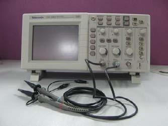
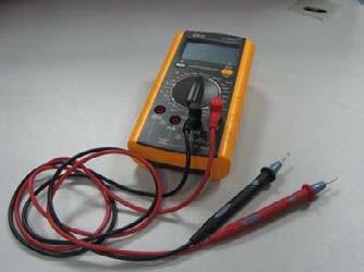
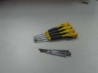
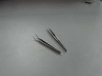
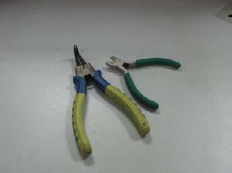


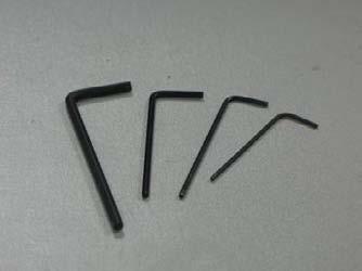
2 1 KTS 440RC SERIES TOTAL STATION SERVICE MANUAL Tools Oscillograph Multimeter Collimator Screw driver Pliers Allen Key Tweezers Polishing Sticks Cotton Lubricant Alcohol with ether Green Grease GUANGDONG KOLIDA INSTRUMENT CO., LTD. 1

, Please follow the below steps for the disassembly of the instrument, as well as the assembly. For repairing or replacement, please take the related chapter as reference.")
3 2 KTS 440RC SERIES TOTAL STATION SERVICE MANUAL Disassembly and assembly Preparation: Please keep your hands clear and prepare the tools as follows: screwdriver, tweezers, pliers, Allen Key and alcohol ready. Prepare a tray for collecting the screws. Prepare a notebook for recording the position of the connection points and the color of wires when necessary. Contents: This chapter mainly introduced the standard disassembly procedure of KTS-440RC. (Absolute encoding), Please follow the below steps for the disassembly of the instrument, as well as the assembly. For repairing or replacement, please take the related chapter as reference. After assembly, all screw should be coated with varnish except those on vertical disk cover, EDM cover, slip-ring cover etc. The factory might upgrade some of the spare parts, if you find some differences between this manual and the instrument, please contact us. Step: 1. Remove the cover of vertical disc system Loosen off the six screws on the left cover with a screwdriver, and then open the cover carefully. When opening the cover, please pay attention to the wire between the angle-measuring board and the buzzer. Pull out the plug so that you can remove the cover freely. GUANGDONG KOLIDA INSTRUMENT CO., LTD. 2


4 3 KTS 440RC SERIES TOTAL STATION SERVICE MANUAL 2. LCD Panel Remove the LCD Panel carefully after Loosening off the six screws Before removing the LCD Panel, please be careful the flat cable on the back. First open the flat cableclamp on the direction of red arrow, and then pull out the flat cable, both of the LCD and the flat cable are fragile, please be careful. Loosen off the four screws on the LCD BACK COVER with a Screwdriver and then remove it. Open the flat cable-clamp on the direction of red arrow, and then pull out the flat cable on the angle-measuring board carefully. 3. Angle-measuring board It is same as the step 1: remove the cover, loosen off the four screws on the angle-measuring board. Pull out the plugs carefully, and record the position of each plug for assembly. Please keep the anglemeasuring board appropriately and safely. GUANGDONG KOLIDA INSTRUMENT CO., LTD. 3


5 4 KTS 440RC SERIES TOTAL STATION SERVICE MANUAL 4. Right Cover Refer to step 2, remove the LCD, and Cut the nylon cable tie with pliers. Do not cut the wires. Loosen off the six screws on the right cover and then open it. When opening the cover, please pay attention to the wire. Pull out the plug, and then you can remove the cover freely. GUANGDONG KOLIDA INSTRUMENT CO., LTD. 4


6 5 KTS 440RC SERIES TOTAL STATION SERVICE MANUAL 5.EDM Cover Loosen off the four screws on the EDM cover and then remove the EDM cover carefully. Make sure that the telescope tangent screw is locked up in case of scuffing the instrument when you loosen those screws. 6. Distance-measuring board Set the instrument telescope in reversed position, and then remove the cover on top of the EDM. Loosen off the four screws on the distancemeasuring board with a screwdriver. Pull out the plugs carefully; record the position of each plug for reference. Pull out the signal plug carefully according to the direction of red arrow. Finished those steps above, reverse the board, you will see the receiving fiber is still connected with the distance-measuring board. Be careful with the fragile fiber. Loosen a little the small screw on the top of the receiving fiber base with Allen key, then pull out the fiber carefully, and remove the main board. GUANGDONG KOLIDA INSTRUMENT CO., LTD. 5


7 6 KTS 440RC SERIES TOTAL STATION SERVICE MANUAL 7. Fibers We applied forficate fiber in the KTS-440 series. As shown in the following figure, there is a mixed-receiving end and which divides into two fibers; one is for inside path receiving, the other for outside path receiving. Mixed-receiving end Inside path receiving fiber Outside path receiving Refer to step 5, 6. Remove both covers of EDM and the distance-measuring board. On one side with motors and receiving fiber, you can find a small screw; loosen it a little till you can pull out the inside path fiber. As shown in figure. Turn the EDM over; loosen off the four screws on the metal cover, and pull the fiber out carefully from the hole in the middle of the metal board. Outside path fiber base GUANGDONG KOLIDA INSTRUMENT CO., LTD. 6


8 7 KTS 440RC SERIES TOTAL STATION SERVICE MANUAL As shown in figure, loosen a little the small screw and then pull out the outside path fiber, till now we remove the whole fiber. Since the fiber is very easily broken, please keep it appropriately and safely. 8. Vertical absolute encoding disc systems Refer to step 1 and 3, remove the vertical disc cover and the angle measuring board. Loosen off the 4 screws in A area and the other 4 in B area. Now you can take off the vertical disc dust cover. A B Loosen off the 4 screws in C area and the other 3 in D area. c In the red circle area, there are 4 black flat head CCD holding screws. Do not loosen them when remove the vertical disk. D GUANGDONG KOLIDA INSTRUMENT CO., LTD. 7


9 8 KTS 440RC SERIES TOTAL STATION SERVICE MANUAL Fallow the steps to assemble the Vertical absolute encoding disc system: Assemble the two vertical angle CCD sensor first. Attention to this little triangle mark on the edge of the vertical disc, this is the 0 angle mark. As shown in figure, set the telescope in normal, assemble the vertical disk system into the appropriate position carefully. Align the holes for screws between the EDM and the vertical disk, and at the same time make sure the small triangle mark is near by the lower CCD. This is very important, if the triangle mark is not in the right position after assembling the disk system, the vertical angle-value reading will be wrong. Tighten all the screws when finished those steps above. And do not forget the washer during assembling. GUANGDONG KOLIDA INSTRUMENT CO., LTD. 8


10 9 KTS 440RC SERIES TOTAL STATION SERVICE MANUAL 9.Vertical CCD unit Refer to step 1, 3, 8, remove the vertical disk cover,distance measuring board and vertical disk system. Loosen off the 4 screws to disassemble the CCD unit. With the same way, remove another one in the opposite position. 10. CCD Bracket Refer to step 1, 3, 8, and 9, remove vertical disk cover, angle-measuring board, vertical-disk system, and vertical CCD unit. Then turn over the vertical disk, there is a copper nut, loosen it off with pliers. Take out vertical disc from bracket. Please keep them appropriately and safely. 11. Vertical tangent screw Refer to step 4, remove the slip-ring cover. Loosen a little the two small screws with Allen key. Press the end of vertical brake-ring system according to the direction of red arrow, at the same time pull out the vertical tangent screw carefully. GUANGDONG KOLIDA INSTRUMENT CO., LTD. 9


11 10 KTS 440RC SERIES TOTAL STATION SERVICE MANUAL 12. Slip-ring Refer to step 1, remove the vertical disk cover and disconnect the slip ring plug form the angle measuring-board. Refer to step 2, remove the LCD on Left side and the back cover. Refer to step 4, cut the cable tie and pull out the slip ring wire. Then loosen off the two screws as shown in figure. Refer to step 6. Pull out the 4-pin slip ring plug from the distance measuring board. Record the color and the position of each wire then pull them out carefully with tweezers, please keep the plug appropriately and safely. Loosen off the 3 screws as shown in figure then pull out the slip-ring unit Vertical brake-ring Refer to step 4, 11, and 12, remove the slip-ring cover, telescope tangent screw, and the slip ring. Loosen off the 3 screws as shown in figure, and remove the vertical brake ring. GUANGDONG KOLIDA INSTRUMENT CO., LTD. 10


12 11 KTS 440RC SERIES TOTAL STATION SERVICE MANUAL 14. Axle sleeve Refer to step 4, 10, 11 and 12, remove the slip-ring cover, vertical telescope tangent screw, slip ring, and the vertical arresting gear ring. Loosen off the 4 screws as shown in figure, hold the EDM, and pull out the axle sleeve with your hands. If it is blocked, do not force to remove the axle sleeve, please send the instrument back to the factory. 15.EDM Refer to step 1-14, turn the EDM to reverse position, hold the EDM with both of your hands, and take it out according to the direction of red arrow. Be careful, do not drop the EDM. GUANGDONG KOLIDA INSTRUMENT CO., LTD. 11


13 12 KTS 440RC SERIES TOTAL STATION SERVICE MANUAL 16. Compensator Refer to step 1 and 4, remove the vertical disk cover, compensator plug on the angle measuring board, left side LCD and back cover, then cut the cable tie, pull out the compensator wire, open the slip ring cover. Loosen off the 2 screws as shown in figure, then you can take out the compensator freely. 17. Horizontal tangent screw Refer to step 2, remove the right side LCD and back cover. Loosen the two little screws with Allen key; press the end of horizontal brake ring system according to the direction of red arrow, at the same time pull out the tangent screw carefully. 18. Horizontal disc and vertical axle unit Refer to step 1, 2, 3, 4, 5, and 17, remove the vertical disk cover, slip ring cover, both of the LCDs and back covers, cut off the cable tie, and pull out the CCD plugs, remove one EDM cover and the horizontal tangent screw. Take off the 4 rubber cover. Loosen off the 3 screws with Allen key. Disassemble the tribrach. GUANGDONG KOLIDA INSTRUMENT CO., LTD. 12


14 13 KTS 440RC SERIES TOTAL STATION SERVICE MANUAL Turn over the instrument and loosen off the screws on the back cover. Use Allen key to loosen off the 3 base holding screws, and then take off the base, then loosen off the 6 dust cover holding screws and take off the dust cover. Hold the instrument body with both of your hands, and then move it up carefully. Pay attention to the horizontal brake ring system, and the CCD wire. 19. Horizontal CCD unit Refer to step 18, disassemble the horizontal disc and vertical axle unit, loosen off the screws on the CCD unit, then you can remove the CCD unit. GUANGDONG KOLIDA INSTRUMENT CO., LTD. 13


15 14 KTS 440RC SERIES TOTAL STATION SERVICE MANUAL 20. Vertical axle unit Refer to step 18 and 19,, disassemble the horizontal disc and vertical axle unit, then disassemble the CCD unit, disassemble the tribrach. Turn over the horizontal disc and vertical axle unit; loosen off the screws on the back cover. Be careful with the horizontal angle disc. Loosen off the copper nut with Allen key. Move the base up according to the direction of red arrow. You will find the vertical axle and the base are separated. Tips: upturn the base and keep the steel balls from dropping. If any steel ball lost, the whole steel balls will fail to work because they are unique set for each instrument. Put the steel bolls in a container immediately after removing the axle GUANGDONG KOLIDA INSTRUMENT CO., LTD. 14


16 15 KTS 440RC SERIES TOTAL STATION SERVICE MANUAL 21. Plate vial Loosen off the plate vial adjusting. Refer to step 3, remove the left LCD along with its back cover, loosen off the screws as shown in figure, then remove the plate vial. 22. Optical plummet Refer to step 3, remove the LCD and its back cover on the left of slip-ring. Use Allen key loosen off the 2 little screws on the Optical plummet. Pull out the optical plummet carefully, and keep it appropriately and safely. The assembling of optical plummet: level the instrument on the tripod, insert the optical plummet to the instrument then look into the eyepiece. Turn the plummet until you can see a complete view, then tighten the 2 little screws. GUANGDONG KOLIDA INSTRUMENT CO., LTD. 15


17 16 KTS 440RC SERIES TOTAL STATION SERVICE MANUAL 23. Eyepiece and cross hair Screw off the eyepiece cover and the eyepiece. By loosening off the four screws inside, you can remove the cross hair freely. Summary: This is the disassemble process of KTS-450RC series, however, the disassemble instruction for some components are not mentioned here, such as: luminotron, motor, the inside path prism, telescopic tube etc. As the most of them could not be assembled without special tools, we suggest you do not try to dissemble them by yourself GUANGDONG KOLIDA INSTRUMENT CO., LTD. 16
 Electronic failure Replace angle measuring board Error 2 telescope rotated too fast (protecting error) Error 3 Main body rotated too fast.")

18 17 KTS 440RC SERIES TOTAL STATION SERVICE MANUAL Common problem for angle measuring Error code 1-7 Adjusting the gap between copper nut and axle sleeve Mechanical failure Tighten Center screw Error 1 Horizontal CCD (adjusting or replace) Electronic failure Replace angle measuring board Error 2 telescope rotated too fast (protecting error) Error 3 Main body rotated too fast. Error 4, Error 7 Vertical CCD unit A: bad signal (adjusting the signal) B: dust on disc (clean the disc) C: CCD unit broken, or dust on the surface of CCD (replace or clean) D: Sun radiation on the disc. E: Main board broken. ERROR 5, Error 6 Horizontal CCD unit A: bad signal (adjusting the signal) B: dust on disc (clean the disc) C CCD unit broken, or dust on the surface of CCD (replace or clean) D: Sun radiation on the disc. E: Main board broken. GUANGDONG KOLIDA INSTRUMENT CO., LTD. 17
, return it to the factory.")
19 18 KTS 440RC SERIES TOTAL STATION SERVICE MANUAL Battery Battery voltage< 5.5 V. the working voltage should be: 5.5v-7.5v Check the power supply wire inside the right cover and the weld point. No display The LCD unit and the flat cable. or can not power on Mainboard: Programming error (CPU), return it to the factory. Axle blocked Dust inside axle sleeve (clean dust) Vertical axle blocked Axle (Rusty, Moldy, Tilt) (polishing) The gap between copper nut and axle sleeve (fix gap) Polishing process: When the vertical axle blocked, please do not try to rotate the instrument, otherwise it will damage the vertical axle and axle sleeve. Steps: (1)Refer to step 1-20 in dissembling chapter, take out the vertical axis. (2)Clean the lubricant on the vertical axle. GUANGDONG KOLIDA INSTRUMENT CO., LTD. 18
Set the polishing tool on the vertical axle then rotate it 2-3 rounds clockwise.")
Daub polishing powder on the polishing stick then put it into the axle sleeve and rotate it 2-3 rounds clockwise.")

 Axle (Rusty, Moldy, Tilt) (polishing) Polishing")
20 19 KTS 440RC SERIES TOTAL STATION SERVICE MANUAL ((3)Daub polishing powder (Green grease) on the vertical axle. (4)Set the polishing tool on the vertical axle then rotate it 2-3 rounds clockwise. (5)Take out the axle, and clean the polishing powder. Polishing axle sleeve. (6)Daub polishing powder on the polishing stick then put it into the axle sleeve and rotate it 2-3 rounds clockwise.. (7)Take out the polishing stick and clean the axle sleeve. (8)Assemble the axle and axle sleeve (base unit). If the axle can rotate smoothly, that means the polishing process succeeds. (9)If the vertical axle still blocked, please repeat the steps 2-8. Horizontal axis blocked Axle and axle sleeve position changed (fix position) Axle (Rusty, Moldy, Tilt) (polishing) Polishing process: When the horizontal axle blocked, please do not try to rotate the telescope, it will damage the horizontal axle and axle sleeve. 1)Refer to step 10 in dissemble chapter. Disassemble the horizontal GUANGDONG KOLIDA INSTRUMENT CO., LTD. 19
Set the polishing tool on the horizontal axle then rotate it 2-3 rounds clockwise. (5)Take out the axle, and clean the polishing powder. Polishing axle sleeve.")
Assemble the axle and axle sleeve. If the axle can rotate smoothly, that means the polishing process succeed. (9)If the horizontal axle still blocked, please repeat the steps 2-8.")

21 20 KTS 440RC SERIES TOTAL STATION SERVICE MANUAL axle and axle sleeve. (2)Clean the lubricant on the horizontal axle. (3)Daub polishing powder (Green grease) on the horizontal axle. (4)Set the polishing tool on the horizontal axle then rotate it 2-3 rounds clockwise. (5)Take out the axle, and clean the polishing powder. Polishing axle sleeve. (6)Daub polishing powder on the polishing stick then put it into the axle sleeve and rotate it 2-3 rounds clockwise. (7)Take out the polishing stick and clean the axle sleeve. (8)Assemble the axle and axle sleeve. If the axle can rotate smoothly, that means the polishing process succeed. (9)If the horizontal axle still blocked, please repeat the steps 2-8. Display unit One display unit failure may leads both of two displays fail to work. Please change it one by one to find out which one is broken. Communication port fault maintenance Make sure the communication cable is good and connection between computer and TS is steady. The communication port is well connected with the mainboard. And check the baud rate. If the fault still can not be ruled out, please change the main board. GUANGDONG KOLIDA INSTRUMENT CO., LTD. 20

22 21 KTS 440RC SERIES TOTAL STATION SERVICE MANUAL The name for angle-measuring board Upper CCD unit socket Buzzer socket Bottom CCD unit socket Slip-ring socket Horizontal CCD unit socket for short wire COM socket Horizontal CCD unit socket for short wire Compensator socket LCD socket SD card cable socket LCD socket Power supply socket GUANGDONG KOLIDA INSTRUMENT CO., LTD. 21
. If not: main board. 1.Check the power supply to EDM board. It should be 6V.")
check the battery supply the power voltage to angle mainboard or not. 2.Check the motors working voltage, it should be 2.")


23 22 KTS 440RC SERIES TOTAL STATION SERVICE MANUAL EDM fault maintenance EDM test process: 1.Check out the motors are working or not after power on the instrument. (It sounds like click ). If not: main board. 1.Check the power supply to EDM board. It should be 6V. if there is no power supply: (1)check the slip ring is short circuit or not, or broken, replace the slip ring. (2)check the power supply from angle mainboard to slip ring. If there is no power supply, replace the angle (3)check the battery supply the power voltage to angle mainboard or not. 2.Check the motors working voltage, it should be 2.5V, if not, replace the EDM main board, check the motors voltage in the test state (factory mode). (1)Mode motor and inside/outside path motor voltage will be always 2.5V. (2)Test light Reduce motor when it is working. 3.Check whether the motor is broken or not. If broken, replace a new one. 2.Check the laser comes out or not, if not: The emitting tube working voltage should be 3v. If there is no power supply from measuring board to emitting tube, replace the measuring board. If the power supply is good, then replace the emitting tube. 3.Check the signal level: Power on, press ESC, press [CNFG] and then press [F1] 5 times [F4] 3 times. Select [F2 EDM STATE], enter test mode. Press [FNC] to switch to state 3, press [F2] to input the working voltage. The working voltage is pasted on the EDM main board. GUANGDONG KOLIDA INSTRUMENT CO., LTD. 22

Inside path signal should be 1000-1500 mv.")

![Press [F4] to switch the tape from 0-5, their signal should be 1000-1500 mv, if one of them not under](/docs-images/72/67088277/images/24-3.jpg "the rage, replace the measuring board.")
In STATE 1, switch the measure mode to PRISM. The measure mode motor will drop down the filter.")

24 23 KTS 440RC SERIES TOTAL STATION SERVICE MANUAL 2 In Non-Prism mode, shot on the white wall, outside path signal should be mv (The signal is relativity by the reflector and distance.) If the signal is very weak, the fiber maybe broken, replace the fiber. (3)Inside path signal should be mv.(prism or Non-Prism mode) if not, loosen the inside filter holding screw near the fiber. Turn the inside path filter to change the signal; tighten the screw when the signal in the working range. Press [F4] to switch the tape from 0-5, their signal should be mv, if one of them not under the rage, replace the measuring board. If all the tapes could not be adjusted to the right range, replace the fiber or measuring board. (4)In STATE 1, switch the measure mode to PRISM. The measure mode motor will drop down the filter. The filter will block the laser and only allows a small quantity laser come through the filter from the gap in the center. When the laser comes out, the gap should be in the center of the laser blocked on the filter. If not, loosen the fix screws to adjust the position until the gap in the center of the laser, and tighten the fix screws, put some varnish on fix screws. GUANGDONG KOLIDA INSTRUMENT CO., LTD. 23
 3 axes: sight axis, emitting axis, receiving axis.")
Set the total station on the tripod and level it.")

Match the two crosshairs together between TOTAL STATION and crosshair-board.")

25 24 KTS 440RC SERIES TOTAL STATION SERVICE MANUAL 4.Check and Adjust 3 axis.(before adjust 3 axis, make sure 2C is correct. Refer to total station Calibration the 4 th section) 3 axes: sight axis, emitting axis, receiving axis. (The 3 axis should be match together, if not, it will cause the instrument can not measure long distance. 1.check and adjust Emitting axis (1)Set the total station on the tripod and level it. Put a crosshair-board 50 Meter away from total station. Turn on the instrument, enter the test mode. Select Non-Prism in State 1 to let the laser comes out from the Lens center. (2)Set up a theodolite beside the total station. Use for observe the laser dot on the crosshair-board. (3)Match the two crosshairs together between TOTAL STATION and crosshair-board. (4)Adjust screw 1,2 which on the base board to move the laser point to the left or right. loosen screw 3,4 then turn the redirection mirror to move the laser point up or down, until the laser dot in the center of the crosshair. 1,2 3,4 Redirection mirror Focus Prism Holding SCREW (5)loosen the holding screw then Turn the focus prism clockwise to make laser point focus. Tight the holding screw. GUANGDONG KOLIDA INSTRUMENT CO., LTD. 24


26 25 KTS 440RC SERIES TOTAL STATION SERVICE MANUAL 2. Check and adjust Receiving axis Check the receiving axis to see if it is matched together with the sight axis. if not, adjust the receiving fiber base. Refer to Chapter: disassembly step 6,7, pull out the mix-receiving end from the measuring board. Focus the total station to infinity. As shown in figure, use a theodolite aim at the total station lens, turn the theodolite zoom ring utill you can see total station crosshair clearly. Aim the mix-receiving end to a light. As shown in figure, we can see a light dot through the theodolite eyepiece. If you can not see the light dot, you need to adjust the outside path receiving fiber to Focus the light dot until you can see it clearly. Loosen the outside path receiving fiber holding Screw, Move the fiber up and down to focus the light dot, when finished, Tighten the holding screw. Loosen three screws on the fiber base as shown in figure. Move the fiber base to make the light dot in the center of the total station crosshair. Finally, tighten those screws and put varnish on them. GUANGDONG KOLIDA INSTRUMENT CO., LTD. 25


27 26 KTS 440RC SERIES TOTAL STATION SERVICE MANUAL 5. Test Point on the EDM Board 1,the socket and plug on the EDM board: Emitting Fiber signal and Power supply plug. Slip ring socket 3 Motors Power Supply socket forficate fiber mixreceiving end socket Optical coupling unit socket GUANGDONG KOLIDA INSTRUMENT CO., LTD. 26
 Power supply for measure tape Working voltage is 4.9v CPU power supply 3.6V Battery Power supply 6V. Same as slip ring Emitting fiber working voltage, 3.")
28 27 KTS 440RC SERIES TOTAL STATION SERVICE MANUAL 2, EDM board test point Working voltage test point, same as the sticker on the EDM board (this board is 173.2V) Power supply for measure tape Working voltage is 4.9v CPU power supply 3.6V Battery Power supply 6V. Same as slip ring Emitting fiber working voltage, 3.3V GUANGDONG KOLIDA INSTRUMENT CO., LTD. 27


29 28 KTS 440RC SERIES TOTAL STATION SERVICE MANUAL 6. Optical coupler Optical coupler is used for estimating the distance between total station and target. The emitting and receiving diode on the optical coupler are connected together and looks like a U. Make sure the black edge of the light filter inside the U. (Emitting diode and receiving diode.) GUANGDONG KOLIDA INSTRUMENT CO., LTD. 28
30 29 KTS 440RC SERIES TOTAL STATION SERVICE MANUAL Common faults and errors. (1) Outside path signal too weak, fiber broken or EDM board broken, replace fiber or EDM board (2) The measuring functions fail to work under Prism Mode, but pretty good under Non-prism mode. Fiber broken or EDM board broken, replace fiber or EDM board (3) At times, the instrument does work properly in Non prism mode. Inside path motor against with other parts, fix the motor position. or EDM board broken, replace it. (4) The measuring function totally fails under Non-Prism mode. Check the fiber and upgrade the program, check the EDM board. (5) Measure speed is slow. Upgrade the EDM program, connect the PC, Press F3 and power on, upgrade the program. (6) The instrument is failed to measure distance. Check the instrument step by step according this chapter. (7) Aim at the prism center, the instrument doesn t shoot distance, offset the crosshair from the prism center, the instrument start shoot distance. The instrument only measure short distance, but doesn t measure long distance. Check and Adjust 3 axis (8) The measure result is not stable, inside path signal is too strong, adjust the signal according this chapter Check the signal level GUANGDONG KOLIDA INSTRUMENT CO., LTD. 29

31 30 KTS 440RC SERIES TOTAL STATION SERVICE MANUAL Calibrations Preparation: Please prepare screw driver, adjusting pin, varnish, hexagon wrench, level the instrument on the collimator, wash your hands and get ready. Content: This chapter mainly introduces you the standard adjusting process, the following steps should be finished on the collimator. Except the adjustment of optical plummet, the other steps should follow the given order; otherwise you can t get the wrong result. Process: 1. Plate Vial C Level the instrument on the collimator. As shown in the figure, rotate instrument, make plate level parallel in the center of leveling screw A and B, and then adjusts leveling screw to make plate bubble centered. A B Turn the instrument for 90 degrees, adjust the third leveling screw, and make the plate bubble centered. Repeat the steps 1 and 2, make the plate bubble centered in above two positions. C A B Rotate instrument 180. If the plate bubble not centered, adjust the fix screw, move the plate bubble a half of the difference; C A B GUANGDONG KOLIDA INSTRUMENT CO., LTD. 30


32 31 KTS 440RC SERIES TOTAL STATION SERVICE MANUAL 2. Circular Vial After examining the plate bubble, circular bubble should be centered too (or not beyond the reticle circularity), which indicates the circular bubble is vertical to vertical axis. if not the adjustment steps are as follows. 1. Loosen the screw (one or two) opposite with bubble deflective direction; 2. Tweak tightly the screw on the direction accordant deflective until circular bubble is centered; 3. Adjust three adjustment screws for several times until circular bubble is centered; 4. The force power fixing three adjustment screws must be consistent when circular level is centered at last. 3. Cross Hair Make sure the collimator crosshair is good. Try to match the total station crosshair center and collimator crosshair center together. If the two crosshair matched perfectly, means the total station crosshair is good. As shown in figure. If the total station crosshair is tilt, then you have to calibrate it. Take off the eyepiece cover, Loosen the three crosshair holding screws; move the crosshair base to match the two crosshair together then Tighten screws, and then daub a little varnish on those screws. GUANGDONG KOLIDA INSTRUMENT CO., LTD. 31
 Level the instrument; aim at the collimator, match the total station crosshair with one of the horizontal scales on the collimator")
33 32 KTS 440RC SERIES TOTAL STATION SERVICE MANUAL 4. 2C (Perpendicularity between Sight Axis and Horizontal Axis) Level the instrument; aim at the collimator, match the total station crosshair with one of the horizontal scales on the collimator crosshair. And press 0set (F1) Reverse the telescope and aim at the same scale, and read the horizontal angle value, which should be 180 ±8. As shown in the figure, the value of HR is It means the 2C is +40, we have to adjust it. NTS-360R series total station has two way to calibrate 2C: Solution 1: mechanical calibration Turn the horizontal tangent screw to make the horizontal angle value to '20" ---- half of the 2C value. See the shown figure. Look at the crosshair, the crosshair moved a little from the scale (gray area), take off the eyepiece cover and adjust the left and right adjusting screws to make the crosshair back to match the scale again. The principle is loosen one adjusting screw before tighten another. After the adjustment, check the 2C again, if it still over ±8, please do it again. When 2C > 1, it will affect the 3 axis. First, you have to fix the 2C, then check and adjust the 3 axis, otherwise it will affected the distance measurement. GUANGDONG KOLIDA INSTRUMENT CO., LTD. 32

![when 2C < 2 ) Press CNFG; choose [2.Instr, const].](/docs-images/72/67088277/images/34-2.jpg "Then choose [3.")
![Collimation] Level the instrument; aim at the](/docs-images/72/67088277/images/34-3.jpg "collimator, match the total station crosshair with")

![Press [F4] choose ok, go to step 2 Reverse the](/docs-images/72/67088277/images/34-7.jpg "telescope and aim at the same scale.")
34 33 KTS 440RC SERIES TOTAL STATION SERVICE MANUAL Solution 2:Electronic calibration (only can use when 2C < 2 ) Press CNFG; choose [2.Instr, const]. Then choose [3. Collimation] Level the instrument; aim at the collimator, match the total station crosshair with one of the horizontal scales on the collimator crosshair. Press [F4] choose ok, go to step 2 Reverse the telescope and aim at the same scale. Press F4, the calibration process ends up with <SET!> on the screen. GUANGDONG KOLIDA INSTRUMENT CO., LTD. 33
 Inspection Steps and")


, do the same procedure as above,")

 According to the red arrow, move the axle sleeve up and down to")
35 34 KTS 440RC SERIES TOTAL STATION SERVICE MANUAL 5. High-low Difference (Perpendicularity between Horizontal Axis and Vertical Axis) Inspection Steps and Criterion: On the first position (main board is on your left side), aim at the horizontal collimator, match the total station crosshair with one of the horizontal scales on the collimator crosshair. As shown in figure. Rotate the EDM, Aim at the lower collimator, note down the intersection between total station crosshair and collimator crosshair. LEFT-HR On the second position (main board is on your right side), do the same procedure as above, note down the intersection between total station crosshair and collimator crosshair. LEFT-LOW RIGHT-HR The difference between the two intersections is high-low difference, which should be less than 10 (1 division on the collimator is 30 ) RIGHT-LOW Refer to Disassembly part 4,take off the right cover, Loosen the four screws a little.(notice: DO NOT loosen too much) According to the red arrow, move the axle sleeve up and down to calibrate the high-low difference. As shown in the figure, adjust the axle sleeve till the crosshair move to the white line. (Half of the difference) GUANGDONG KOLIDA INSTRUMENT CO., LTD. 34

36 35 KTS 440RC SERIES TOTAL STATION SERVICE MANUAL After high-low difference, the four screws should be tight to make sure the horizontal axis is steady, daub some vanish on the screws, and do the plate vial calibration after. 6. Compensator Make sure the plate vial is good and level the instrument on the collimator, power on and press esc, you can see the model, number and version of software. Press [SFT] and [.] to enter the compensator calibration program. The figure shows the electronic bubble position. Press [DIGIT] to see the electronic bubble offset. C B A A X direction calibration:loosen two screws in A area a little,knock the left and right side of the compensator, make the X = 0 00'00", then tighten the screws. Y direction calibration:loosen screw C,turning screw B, until Y =0 00'00", then tighten the screws. GUANGDONG KOLIDA INSTRUMENT CO., LTD. 35
 Level the instrument and aim at the collimator (first position), as shown in figure, match the total")


37 36 KTS 440RC SERIES TOTAL STATION SERVICE MANUAL 7. I Angle (Vertical Angle Index error) Level the instrument and aim at the collimator (first position), as shown in figure, match the total station crosshair with one of the vertical scales on the collimator crosshair. As shown in the figure the V1 is Reverse the telescope and aim at the same scale, note down the vertical angle value. As shown in figure the V2 is I angle = (v1+v2-360 )/2. I angle should < ± 6. Otherwise we have to calibrate it. Press CNFG; choose [2.Instr, const] to enter the calibration program. Press F2 selects V0 Adjustment. Level the instrument on the collimator (first position), aim at the collimator as shown in figure, and match the total station crosshair with one of the vertical scales on the collimator. GUANGDONG KOLIDA INSTRUMENT CO., LTD. 36


38 37 KTS 440RC SERIES TOTAL STATION SERVICE MANUAL Press F4 and enter the next step. Reverse the telescope, aim at the collimator as shown in figure, and match the total station s crosshair with the same vertical scales on the collimator. Press F4, the calibration process ends up with <SET!> on the screen. When the Index error is too big to adjust, the system will remind you for mandatory setting after the above steps were done. Press F4 to select OK. After mandatory setting, you should check the index error again according to the above steps. GUANGDONG KOLIDA INSTRUMENT CO., LTD. 37


39 38 KTS 440RC SERIES TOTAL STATION SERVICE MANUAL 8. Optical Plummet Inspection Steps and Criterion Place a picture of crosshair underneath the tripod after the instrument was settled on the tripod. Move the paper until the crosshair overlaps the center of plummet Rotate the instrument every 90 to check whether the center of optical plummet is right above the crosshair center If not, rotate the instrument for 180, and examine the optical plummet center offset distance. Usually, adjust the center of optical plummet halfway to the crosshair center with adjusting pin. As shown in the figure: Take down the optical plummet eyepiece cover, and adjust the four screws inside. As show in the picture, through moving the optical plummet to the center of red crosshair, the gap will be reduced by half. Then, overlap the optical plummet and the crosshair which drawn on the paper. If the gap still exists, repeat the above steps until it disappears GUANGDONG KOLIDA INSTRUMENT CO., LTD. 38
3. Product Instruction. 3.1 External Components
 INDEX INDEX... 0 1. Preface... 1 2. Precautions... 2 3. Product Instruction... 3 3.1 External Components... 3 3.2 Display And Keypad... 4 4. Specifications Check And Adjustment... 5 4.1 Plat Vial... 5
Code Product Qty 1 Top Vertex 3 2 Hot End Housing 1 3 Bottom Vertex 3 4 Print Platform Lock 3 5 End Stop Holder 3 6 Filament Feeder Motor Bracket 1 7
 List of Parts Code Product Qty 1 680mm Extrusion 3 2 Power Supply 1 3 240mm Extrusion 9 4 42mm Nema 17 Stepper Motor 3 5 Slider-Hotend Connecting Rod 6 6 48mm Nema 17 Stepper Motor 1 7 Linear Rail with
Astro-Physics Inc. 400QMD Lubrication/Maintenance Guide
 Astro-Physics Inc. 400QMD Lubrication/Maintenance Guide The following guidelines should be followed to lubricate the three main parts of the 400QMD mount. The QMD stands for Quartz Micro-Drive controller.
Automatic Rotating Laser Service Manual
 40-6515 Automatic Rotating Laser Service Manual Contents Item Description Pages 1.0 Overall Instrument Assembly 2 1.1 Mounting Bracket/Trivot Assembly 2 1.2 Main Housing Assembly 3 1.3 Core Module Assembly
EMO. Service Instruction. created by Frank Weithöner. Table of contents: Special Tools Assembling Mixing Chamber
 EMO Service Instruction created by Frank Weithöner Table of contents: - Special Tools Disassembling Mixing Chamber Assembling Mixing Chamber Adjustment Rotor / Level Indicator Unit Temperature Compensating
Motorized Tower Raising System Manual
 Motorized Tower Raising System Manual Introduction and Safety Guidelines Important! Read through the manual in its entirety prior to assembly and installation of the motorized tower raising system. WARNING:
1. Features Calibration Compensator Lock Button Circular bubble Line-of-sight...10
 CONTENTS 1. Features... 2 2. Using the instrument... 5 2.1 Setting Up and Centering the Bubble...5 2.2 Focusing the Instrument...6 2.3 Reading Measurements Using a Leveling Rod...7 2.3.1 Height Reading...7
Vinyl Cutter Instruction Manual
 Vinyl Cutter Instruction Manual 1 Product Inventory Inventory Here is a list of items you will receive with your vinyl cutter: Product components (Fig.1-4): 1x Cutter head unit complete with motor, plastic
Service Manual for XLE/XLT Series Laser Engravers
 Service Manual for XLE/XLT Series Laser Engravers Table of Contents Maintenance...1 Beam alignment...3 Auto focus alignment...8 Bridge alignment...10 Electronics panel replacement...11 X motor change...12
ABM International, Inc. Navigator Assembly Manual
 ABM International, Inc. 1 1.0: Parts List Tablet (Qty. 1) Tablet mount (Qty. 1) NOTE: Mount may appear and operate different then image below Control Box (Qty. 1) Motor Power Supply (Qty. 1) 2 X-axis motor
3D PRINTER. Pack 11. Anything you can imagine, you can make! 3D technology is now available for you at home! BUILD YOUR OWN
 BUILD YOUR OWN Pack 11 Anything you can imagine, you can make! 3D PRINTER Compatible with Windows 7 & 8 Mac OS X 3D technology is now available for you at home! BUILD YOUR OWN 3D PRINTER CONTENTS PACK
MODULAR BUMPER INSTALLATION MANUAL
 MODULAR BUMPER INSTALLATION MANUAL Parts List* 1 Center section 1 Side extension, passenger / right 1 Side extension, driver / left 1 Side cap, passenger / right 1 Side cap, driver / left 1 Brush guard,
OTHER TOOLS MAY BE NEEDED DEPENDING ON YOUR VEHICLE.
 THIS KIT INCLUDES: 16 M8-1.25X40MM BOLTS WITH WASHERS 2 SHOCKS 720 PSI RIGHT AND LEFT HINGE ASSEMBLY 2 SHOULDER BOLTS 2 PINS TOOLS REQUIRED FOR INSTALLATION: AIR RACHET, GRINDER AND CUTTER. 10MM, 11MM,
ELECTRIC TOOL CORPORATION
 Cat. No. -0 / Hex Demolition Hammer Cat. No. 0-0 Spline Rotary Hammer MILWAUKEE ELECTRIC TOOL CORPORATION W. LISBON ROAD BROOKFIELD, WISCONSIN 00-0 -9-00 d 000 -9-00 d SpecialTools Require Forcing discs
MOTORIZED STANDARD SHADE WITH CABLES Installation Instructions
 Tools Needed Drill Measuring Tape Pencil 2 Level Plumb Line ¼ Masonry Drill Bit Hammer Linesmans Pliers Cable Cutters Phillips & Flat-Head Screw Driver 11/32 Socket or Open End Wrench 5/32 Allen Wrench
Tapping Screw (W/Flange) 46 Cord Armor 47 Tube (D) 48 Cord. 45 Cord Clip. Tapping Screw (W/Flange) 10 Gear Cover Ass'y. 12 Socket (B) Ass'y
 46 Cord Armor 47 Tube (D) 48 Cord. 45 Cord Clip. Tapping Screw (W/Flange) 10 Gear Cover Ass'y. 12 Socket (B) Ass'y") W8VB The exploded assembly drawing should be used only for authoized service center. W8VB Item No. Part time 1 Magnetic Hex. Socket 2 Sub Stopper 3 O-Ring (S-16) 4 Locator (A) 5 Lock Sleeve (A) 6 O-Ring
W8VB The exploded assembly drawing should be used only for authoized service center. W8VB Item No. Part time 1 Magnetic Hex. Socket 2 Sub Stopper 3 O-Ring (S-16) 4 Locator (A) 5 Lock Sleeve (A) 6 O-Ring
TOOLS REQUIRED FOR INSTALLATION: AIR RACHET, GRINDER AND CUTTER.
 THIS KIT INCLUDES: 16 M8-1.25X30MM BOLTS WITH WASHERS 2 SHOCKS 565 PSI RIGHT AND LEFT HINGE ASSEMBLY 2 SHOULDER BOLTS 2 PINS TOOLS REQUIRED FOR INSTALLATION: AIR RACHET, GRINDER AND CUTTER. 7/23, 10MM,
Replacing the build plate clamps
 Repair manual Replacing the build plate clamps Instructions The build plate clamps hold the glass plate in place on the heated bed. There are two fixed in place at the back of the heated bed and two at
SERVICE PARTS LIST PAGE 1 OF 6 BASE ASSEMBLY SPECIFY CATALOG NO. AND SERIAL NO. WHEN ORDERING PARTS 12" SLIDING COMPOUND MITER SAW
 PAGE 1 OF 6 BASE ASSEMBLY 00 0 CATALOG NO. EXAMPLE: SPECIFY CATALOG NO. AND NO. WHEN ORDERING PARTS 6955-20 1 02-80-0050 Thrust Bearing (1) 2 05-80-0510 M5 x 12mm Flat Head T-20 Screw (5) 3 05-81-0135
THIS KIT INCLUDES: 8 M8-1.25X40MM BOLTS WITH WASHERS 8 M8-1.25X30MM BOLTS WITH WASHERS RIGHT AND LEFT HINGE
 Sal es@lambodoorscanada. com 2407A Kal adarave,ottawa,on K1V 8B9 THIS KIT INCLUDES: 8 M8-1.25X40MM BOLTS WITH WASHERS 8 M8-1.25X30MM BOLTS WITH WASHERS RIGHT AND LEFT HINGE 2 SHOCKS 565 PSI 2 SHOULDER
2 SHOULDER BOLTS RIGHT AND LEFT HINGE USE 4 EXISITING DOOR BOLTS TOOLS REQUIRED FOR INSTALLATION: AIR RACHET, GRINDER AND CUTTER.
 Page 1 of 12 NISSAN 350Z 2003-2004 THIS KIT INCLUDES: 8 BOLTS WITH WASHERS 2 SHOCKS 780 PSI 2 PINS 2 SHOULDER BOLTS RIGHT AND LEFT HINGE USE 4 EXISITING DOOR ASSEMBLY BOLTS TOOLS REQUIRED FOR INSTALLATION:
Repairing Microsoft Wedge Touch Mouse Battery Cover Retaining Clip
 Repairing Microsoft Wedge Touch Mouse Battery Cover Retaining Clip Disassembly, repair and reassembly of Wedge Touch mouse when the battery cover will not stay closed. Also is a good guide to repair other
UNPACKING. Thank you for purchasing the Manual Capsule Filling Machine from KARISHMA PHARMA MACHINES.
 UNPACKING Thank you for purchasing the Manual Capsule Filling Machine from KARISHMA PHARMA MACHINES. Please take sufficient time and read this manual carefully before you start installation and operation
REPAIR INSTRUCTIONS. Cat. No Cat. No MILWAUKEE ELECTRIC TOOL CORPORATION. SDS Max Demolition Hammer. SDS Max Rotary Hammer
 Cat. No. 9-0 SDS Max Demolition Hammer Cat. No. -0 SDS Max Rotary Hammer MILWAUKEE ELECTRIC TOOL CORPORATION W. LISBON ROAD BROOKFIELD, WISCONSIN 00-0 8-9-0 d 000 8-9-0 d Special Tools Require Forcing
Repair manual. Fifth-wheel coupling JSK 38/50
 Repair manual Fifth-wheel coupling JSK 38/5 ZDE 199 3 12 E 6/212 1 Foreword Table of contents Page Fifth wheel couplings are connecting parts that must comply with very high safety requirements and must
The Astronomical League
 The Astronomical League www.astroleague.org Library Telescope Modifications Check the collimation with the eyepiece cap provided (the one with the hole in its center) before starting on any modifications.
7878 K940. Checkpoint Antenna. Kit Instructions. Issue B
 7878 K940 Checkpoint Antenna Kit Instructions Issue B Revision Record Issue Date Remarks A July 7, 2009 First issue B Nov2013 Revised the Checkpoint installation procedures for 7878 and 7874 scanners Added
Hydrajaws Safety Lifeline Tester
 Hydrajaws Safety Lifeline Tester Operating Instructions HYDR AJAWS LIMITED Hydrajaws Safety Lifeline Tester 4 5 1 6 7 2 3 9 10 8 12 11 TECHNICAL SPECIFICATIONS Load Gauges Range available: Analogue: 0-25kN/lb/f
XT-4015 Disassembly Assembly Guide
 XT-4015 Disassembly Assembly Guide Main Unit Disassembly Remove the two screws that in the back of main unit from base as shown. Remove the two screws by turning the main unit to the other side while removing
INSTALLATION & ADJUSTMENT INSTRUCTIONS FOR LETHAL WEAPON MODEL 150 & MODEL 200 SIGHTS AND ACCESSORIES
 Sight Assembly...................2 Mounting Sight on Bow: LW 1.........................2 LW 2.........................3 LW MAX.....................3 Set-Up and Adjustment: 2-Axis Leveling................4
N. 15th Street, Middlesboro, KY FLIP TARP DUMP BODY INSTALLATION INSTRUCTIONS
 1-800-248-7717 1002 N. 15th Street, Middlesboro, KY 40965 FLIP TARP DUMP BODY INSTALLATION INSTRUCTIONS Congratulations on your purchase of a Mountain Flip Tarp Dump Body tarping system. With tarping systems
WARNING: Prior to installation, turn the power off to the vending machine and unplug it from its power source. Also, make sure to level the machine.
 Installation of Gum and Mint Tray for National 147, 157, 167 Important Note: Please read all instructions thoroughly before continuing with installation of kit. If you are having problems installing the
CORVETTE CORVETTE REV: Made in USA U.S. PATENT #6,808,223; #6,845,547; #7,140,075; #7,059,655 and other patents pending.
 CORVETTE 2005-2006 CORVETTE 2005-2007 REV: 7-2-07 Made in USA U.S. PATENT #6,808,223; #6,845,547; #7,140,075; #7,059,655 and other patents pending. Page 1 of 12 CORVETTE C6 2005-2007 THIS KIT INCLUDES:
WARNING!! DO NOT LIFT DOORS UP WHEN THE HOOD IS OPEN. THE DOORS WILL HIT THE HOOD!
 WARNING!! DO NOT LIFT DOORS UP WHEN THE HOOD IS OPEN. THE DOORS WILL HIT THE HOOD! THIS KIT INCLUDES: 4 M8-1.25X30MM BOLTS WITH WASHERS 12 M8-1.25X40MM BOLTS WITH WASHERS 2 SHOULDER BOLTS WITH RIGHT AND
Lumber Smith. Assembly Manual. If you are having problems assembling the saw and need assistance, please contact us at:
 Lumber Smith Assembly Manual If you are having problems assembling the saw and need assistance, please contact us at: 804-577-7398 info@lumbersmith.com 1 Step 1 Safety Carefully read the Owners Manual.
Page 1 of 12 GENERAL INSTRUCTIONS KHJKK Installation
 Page 1 of 12 KHJKK PICTURE ABOVE IS THE UNIVERSAL KIT; YOUR KIT MAY BE DIFFERENT. THIS KIT INCLUDES: 8 M8-1.25X30MM BOLTS WITH WASHERS 8 M8-1.25X40MM BOLTS WITH WASHERS 2 PINS RIGHT AND LEFT HINGE ASSEMBLY
INSTALLATION INSTRUCTIONS GRILLE GUARD RAM 1500 PART # 5058/5058-2
 INSTALLATION INSTRUCTIONS GRILLE GUARD PART # 5058/5058-2 PARTS LIST: Qty Description Qty Description 1 Grille Guard 8 12-1.75mm x 35mm Hex Bolts 2 Upper Frame Mounting s (for trucks without tow hooks
400A 40113V, 401A 40120V, & 401AL 40120VL ALUMINUM VERTICAL 4000 LB LIFT INCLUDES SCREW LEG ASSEMBLY INSTRUCTIONS
 12/11/07 PAGE 1 OF 12 400A 40113V, 401A 40120V, & 401AL 40120VL ALUMINUM VERTICAL 4000 LB LIFT INCLUDES SCREW LEG ASSEMBLY INSTRUCTIONS Thank you for purchasing our product! *Please read these instructions
Removing the Z-Axis lead screw
 Page 1 of 8 TITLE: Sabre Z-Axis Lead Screw Replacement Procedure Gerber FastFact #: 5048 Supplied by: Gerber Hardware Support Last Modified: June 14, 2007 Summary: Tools used: The following procedure explains
AX1001. Smith/Functional training Combo-free weight ASSEMBLY INSTRUCTIONS
 AX1001 Smith/Functional training Combo-free weight ASSEMBLY INSTRUCTIONS EXPLODED DIAGRAM 83 84 84 85/86 87 87 88 89 90 91 62 64 64 64 64 64 64 65 65 65 65 66 66 65 66 66 65 63 63 66 67 68 55 66 66 70
Assembly Instructions for Laser Sailboat Dolly (with Beach Wheels for 1 Axle & Ramp Wheels with Reversible Axle)
") Assembly Instructions for Laser Sailboat Dolly (with Beach Wheels for 1 Axle & Ramp Wheels with Reversible Axle)! IMPORTANT: Before you begin, please read these instructions and check to be sure that all
Assembly Instructions for Laser Sailboat Dolly (with Beach Wheels for 1 Axle & Ramp Wheels with Reversible Axle)! IMPORTANT: Before you begin, please read these instructions and check to be sure that all
SERVICE PARTS LIST PAGE 1 OF 6 BASE ASSEMBLY SPECIFY CATALOG NO. AND SERIAL NO. WHEN ORDERING PARTS 12" DUAL BEVEL COMPOUND MITER SAW B27B
 PAGE 1 OF 6 BASE ASSEMBLY 00 0 EXAMPLE: Component Parts (Small #) Are Included When Ordering The Assembly (Large #). SPECIFY CATALOG NO. AND NO. WHEN ORDERING PARTS = Part number change from previous service
Wooden Frame Type Instruction Manual
 Wooden Frame TypeInstruction Manual Thank you for selecting our product. Before starting installation, please read this manual thoroughly to ensure correct installation. Please keep this manual at hand
SAM. Model: STV-C65 LCD Mobile Visualized Stand Instruction Manual. Weight Capacity: 1251bs / 56.7kg Suits LCD Flat Panel Display: 42"-55" Page 20
 SAM Model: STV-C65 LCD Mobile Visualized Stand Instruction Manual Weight Capacity: 1251bs / 56.7kg Suits LCD Flat Panel Display: 42"-55" 20 Step 6 LCD Mobile Lift Stand Model: STV-C65 Cable management
OpenROV. Guide 3 - Electronics. We will now move to the assembly of the electronics that will control the ROV. Written By: OpenROV
 OpenROV Guide 3 - Electronics We will now move to the assembly of the electronics that will control the ROV. Written By: OpenROV 2017 openrov.dozuki.com Page 1 of 33 INTRODUCTION We will introduce soldering
MOTOR & BULK HEAD. A Manual for Repair and Maintenance Technicians
 MOTOR & BULK HEAD A Manual for Repair and Maintenance Technicians CAUTION This manual is designed to help technicians who are already experienced in workshop procedures and know how to handle tools. Only
OWNER'S MANUAL Issue 2 - December 14, 2000
 OWNER'S MANUAL AL Issue 2 - December 14, 2000 Copyright 2000 GAMMA Sports - All Rights Reserved Provided by www.gssalliance.com OWNER'S MANUAL TABLE OF CONTENTS PAGE 1... WARRANTY PAGE 2...FEATURES PAGE
Removing and Replacing the Y-truck
 Service Documentation Removing and Replacing the Y-truck To remove and replace the Y-truck you will need the following tools: 4mm Allen wrench 12mm stamped flat wrench #2 Phillips screwdriver (magnetic
OPERATIONAL MANUAL V1.0. Removing/Replacing Blades
 OPERATIONAL MANUAL V1.0 BLUEROCK WS-212 Wire Stripper Removing/Replacing Blades CAUTION!! IMPORTANT!! DANGER!! WARNING!! DISCONNECT MACHINE FROM POWER BEFORE PROCEEDING!! Estimated Completion Time: 90
Baby Grande or Grande Crank Shade with Cables and Housing Installation Instructions
 Baby Grande or Grande Crank Shade with Cables and Housing Installation Instructions Tools Needed Drill 3/8 Metal Drill Bit Screwdriver (Flat & Phillips) Measuring Tape Pencil 4 Level Plumb Line ¼ Masonry
Fifth-wheel coupling JSK 38/50
 Repair manual Fifth-wheel coupling JSK 38/5 ZDE 199 3 12 E 6/25 1 LT SK38C-3 English RevA Foreword Table of contents Page Fifth wheel couplings are connecting parts that must comply with very high safety
Chapter 6 Frame And Lens Repairs
 Chapter 6 Frame And Lens Repairs 6.1 General Information All maintenance on the frame of the EXO Full-Face mask can be accomplished with common hand tools. 6.2 Lens Replacement Tools required: Dow DC-111
Zoom Stereo Microscope NYMCS-360 Instruction Manual
 Zoom Stereo Microscope NYMCS-60 Instruction Manual This manual is written for stereo microscope NYMCS-60. To ensure the safety, obtain optimum performance and to familiarize yourself fully with the use
Band-Master ATS Nano Pneumatic Banding Tool Operating Instructions
 Band-Master ATS 601-118 Nano Pneumatic Banding Tool CONTENTS 601-118 Overview... 3 Safety.... 5 Initial Tool Set-up... 5 Regulator assembly mounting... 5 Attach tool head to regulator.... 6 Operating instructions...
MAG-CONV Basic, 48, 48R & Midline Front Mount
 Parts Required: Tools Used: Mag Wheels Brakes Brake Rods Mounting Bracket Anti Tippers 7/16" Wrench Screw Driver Rubber Mallet 5/8 Wrench 5mm Allen Wrench Step Execution Figures 1 Remove front 5" total
VARIABLE SPEED WOOD LATHE. Model DB900 INSTRUCTION MANUAL
 VARIABLE SPEED WOOD LATHE Model DB900 INSTRUCTION MANUAL 1007 TABLE OF CONTENTS SECTION...PAGE Technical data.. 1 General safety rules....1-3 Specific safety rules for wood lathe.....3 Electrical information.4
Howie's Laser Collimator Instructions:
 Howie's Laser Collimator Instructions: WARNING: AVOID DIRECT OR MIRROR REFLECTED EYE EXPOSURE TO LASER BEAM The laser collimator is a tool that enables precise adjustment of the alignment of telescope
30DC Speed Lathe Manual
 30DC Speed Lathe Manual The Crozier Model 30DC Speed Lathe is our most popular model. It has many standard features not found on any other machine in its class or price range. Standard Features 3/4 HP
Tin Lizzie 18 Assembly Instructions
 Tin Lizzie 18 Assembly Instructions Revision: 07/29/16 Table of Contents Aides 3 Before You Begin 5 Aides 5 Tools 6 Perfect Stitch Parts 2 12 Modify the Machine 12 Prepare Drill Templates 12 Front Display
Front axle components, overview
 j a t Front axle components, overview 40-1 General Information Load bearing components and parts of the suspension must not be welded or straightened. Vehicles without drive axle must not be moved, or
The Lyra Double Double Mounting System Manual
 The Lyra Double Double Mounting System Manual The Lyra DDMS is a device for quickly connecting two cylinders together. It is specifically designed for connecting a finder scope to a larger telescope without
FABA. Installation Instructions. Conductor Bar System. Publication #FABA-03 3/1/04 Part Number: Copyright 2004 Electromotive Systems
 FABA Conductor Bar System Installation Instructions Publication #FABA-03 3/1/04 Part Number: 005-1062 Copyright 2004 Electromotive Systems 1S 100 Z Installation Instructions Contents: Basic Diagram - -
HQ Precision-Glide Track Upgrade 2 Extension Kit for HQ Studio Frame Part# QF09750
 HQ Precision-Glide Track Upgrade 2 Extension Kit for HQ Studio Frame Part# QF09750 Important Note: Upgrading the track system on the HQ Studio Frame requires the use of this 2 Extension Kit (Part #QF09750),
Please read BOTH these Installation Instructions and the General Instructions prior to installing or operating this equipment.
 Attachment Tab Height: 16-1/2 Serial Number Attachment Tab Width: 24 Please read BOTH these and the General Instructions prior to installing or operating this equipment. 1. Blue Ox towing products and
400GTO Lubrication Guide
 400GTO Lubrication Guide Lubrication Guidelines for the following equatorial mounting: 400GTO Servo with GTOCP2 or CP3 Controller For other 400 models please review other postings as they become available.
YOUNGS MODULUS BY UNIFORM & NON UNIFORM BENDING OF A BEAM
 YOUNGS MODULUS BY UNIFORM & NON UNIFORM BENDING OF A BEAM RECTANGULAR BEAM PLACED OVER TWO KNIFE EDGES & DISTANCE BETWEEN KNIFE EDGES IS KEPT CONSTANT AS l= 50cm UNIFORM WEIGHT HANGERS ARE SUSPENDED WITH
REP Design LLC. 193 Winding Ridge Rd, Southington, CT INSTALLATION INSTRUCTIONS:
 REP Design LLC 193 Winding Ridge Rd, Southington, CT 06489 1-860.426.1894 n7emw@cox.net www.repdesign.us INSTALLATION INSTRUCTIONS: SHD-SO239 Super Heavy Duty SO-239Antenna Mounting System Thank you for
Side Winder R o u t e r L i f t.
 Woodpeckers PRECISION WOODWORKING TOOLS Side Winder R o u t e r L i f t. INSTALLATION INSTRUCTIONS The wrench handle must be pointing left in order to fully insert or remove it. Lift Wrench Once fully
Installing the Partridge RA Extension on Losmandy G11
 Installing the Partridge RA Extension on Losmandy G11 Michael Herman July 20, 2015 Tools: 3/16 inch hex key (allen wrench) [If desired for DEC indicator ring friction improvement: flat screwdriver, and
Maintenance Information
 47104302 Edition 1 November 2012 Cordless Drill/Driver QX Series Maintenance Information Save These Instructions Tool Diagnosis 1. Before servicing this unit, you will need a fully charged battery of known
INSTALLATION INSTRUCTIONS DODGE RAM 2 & 4WD 1500 PART # P5058
 INSTALLATION INSTRUCTIONS 2009-13 DODGE RAM 2 & 4WD 1500 PART # P5058 PARTS LIST: Qty Description Qty Description 1 Grille Guard 12 12-1.75mm Hex Nuts 2 Upper Frame Mounting s (for trucks without tow hooks
Maintenance & Parts list for:
 Maintenance & Parts list for: Industrial gun GB 2 Juni 2017 This Maintenance & Parts list for industrial gun is prepared by : Winchester Europe Service V. Parbst & Søn as a comprehensive maintenance guide
Build the. Steam Locomotive. Pack 05
 Build the Steam Locomotive Pack 05 Build the Steam Locomotive Contents Step by step Stage 29: The leading truck 3 Stage 30: The leading truck 4 Stage 31: The headlamp Stage 32: The smokebox door lock Stage
Hubble GOTO Installation Instruction (1.3, 04/30/2014)
") Hubble GOTO Installation Instruction (1.3, 04/30/2014) 1. Preparation... 1 1.1 Tools required... 1 1.2 AZ GOTO Drive Parts List...1 1.3 ALT GOTO Drive Parts List... 1 2. The Azimuth motor drive installation...2
Hubble GOTO Installation Instruction (1.3, 04/30/2014) 1. Preparation... 1 1.1 Tools required... 1 1.2 AZ GOTO Drive Parts List...1 1.3 ALT GOTO Drive Parts List... 1 2. The Azimuth motor drive installation...2
Nancy s Knit Knacks LLC 4 Yard Option Upgrade Kit Assembly Instructions and User Manual
 Nancy s Knit Knacks LLC 4 Yard Option Upgrade Kit Assembly Instructions and User Manual Thank you for purchasing our 4 Yard Option (4YO) Upgrade Kit. To install this upgrade you are simply going to assemble
Z-Axis Assembly Replacement / Adjustment
 Z-Axis Assembly Replacement / Adjustment TOOLS NEEDED: 1 Set of L-Shaped Allen Wrenches 3 blocks of wood, plastic, or acrylic cut to approximately 2 inches by 3 inches Household grade White Lithium grease
Z-Truck Up-and-Down Motion. Y-Truck Side-to-Side Motion. Head. Squaring Plate. Sliding Plate FIGURE 1: THE CARVEWRIGHT MACHINE
 Setup and use of CarveWright CO2 Powered Dragster Jig The CO 2 powered Dragster Jig will arrive from the factory fully assembled, calibrated, and squared. In order to get the best results, your CarveWright
Installation Instructions for the S-2000 Renlita Door
 ESTCODE ESTCODE Installation Instructions for the S-2000 Renlita Door Refer to the shop drawings to see the specifics that are particular to the door you are installing because we custom design our doors
24" x 24" OSCILLATING SPINDLE MANUAL
 24" x 24" OSCILLATING SPINDLE MANUAL LAGUNA TOOLS 2072 Alton Parkway Irvine, California 92606 Ph: 800.234.1976 www.lagunatools.com 2018, Laguna Tools, Inc. LAGUNA and the LAGUNA Logo are the registered
INSTALLATION INSTRUCTIONS 1PC FRONT BUMPER JEEP JK WRANGLER
 INSTALLATION INSTRUCTIONS PARTS LIST: 1 1PC Bumper 2 8mm x 25mm Hex Bolts 1 Bull Nose Hoop 2 8mm x 16mm Hex Bolts 1 Fairlead Mounting Bracket 6 8mm x 24mm x 2mm Flat Washers 8 12mm x 35mm Hex Bolts 4 8mm
CORVETTE Page 1 of 12 CORVETTE C
 CORVETTE 2005-2006 Page 1 of 12 CORVETTE C5 1997-2004 THIS KIT INCLUDES: 8 M8-1.25X40MM BOLTS WITH WASHERS 8 M8-1.25X30MM BOLTS WITH WASHERS RIGHT AND LEFT HINGE ASSEMBLY WIRE LOOM 2 SHOCKS 565 PSI 2 SHOULDER
Maintenance Information
 16575177 Edition 1 June 2006 Electric Angle Wrench QE8 Series Maintenance Information Save These Instructions General Instructions: Refer to Suggested Tools Parts List for quick reference to the tools
Top spin Nr /
 Top spin Nr. 1840 0000 / 1840 1000 Bedienungsanleitung 21-6680 28052014 / A Made in Germany Ideas for dental technology Top spin Nr. 1840 0000 / 1840 1000 Contents 1. Introduction...2 1.1 Symbols...2 2.
Self-Feeder Soldering Station DSF76D-IW. Operation Manual
 Self-Feeder Soldering Station DSF76D-IW Operation Manual Thank you for purchasing the Self-Feeder Lead Free Soldering Station. Please read this manual before operating the unit. Store this manual in a
QB78 CO 2 Pellet Rifle
 QB78 CO 2 Pellet Rifle Maintenance Instructions Text and photos by George Fox Lang The Chinese QB78 pellet rifle is one of the nicest and most popular CO 2 rifles ever produced. Here are the long-wanted
INVENT3D Printer Kit Disassembly Instructions
 INVENT3D Printer Kit Disassembly Instructions Version 6 AST2 10/26/16 1 I. General Disassembly Instructions Use the case layer drawings to ensure that components are stored in the appropriate location
Printrbot Simple (Model 1403) Rev F Printrboard
 Rev F Printrboard") Printrbot Simple (Model 1403) Rev F Printrboard Printrbot Simple is currently shipping with the Rev F Printrboard. Check which rev Printrboard your Simple kit includes and use the corresponding instructions.
Printrbot Simple (Model 1403) Rev F Printrboard Printrbot Simple is currently shipping with the Rev F Printrboard. Check which rev Printrboard your Simple kit includes and use the corresponding instructions.
INSTALLATION MANUAL FRONT. See pages 2 and 3 of this manual for configuration options. Level of Difficulty. Product Photo (center section only)
") INSTALLATION MANUAL FRONT Level of Difficulty Moderate Product Photo (center section only) All hardware listed below will be provided with the bumpers center section. Additional hardware will be supplied
INSTALLATION MANUAL FRONT Level of Difficulty Moderate Product Photo (center section only) All hardware listed below will be provided with the bumpers center section. Additional hardware will be supplied
Operating Manual MRL-101
 Operating Manual MRL-101 Maintenance and Safety While the instrument is operating, be careful not to expose your eyes to the laser beam. Direct exposure to a laser beam for a long time may be hazardous
These Installation Instructions are valid for antennas in the following version:
 Installation Instructions 4 ft CompactLine Antennas (with E-Mount 200 km/h) SB, SBX NMT 480-12(e) These installation instructions have been written for qualified, skilled personnel. The antenna shall be
VARIABLE SPEED WOOD LATHE
 MODEL MC1100B VARIABLE SPEED WOOD LATHE INSTRUCTION MANUAL Please read and fully understand the instructions in this manual before operation. Keep this manual safe for future reference. Version: 2015.02.02
C a r r i a g e A s s e m b l y R e p l a c e m e n t
 E1 TF-CR C a r r i a g e A s s e m b l y R e p l a c e m e n t October 2007 Software Version 5.0 and higher IMPORTANT! TigerStop must be enabled with a code that must be obtained from TigerStop Customer
machines 608 Trestle Point Sanford, FL Phone Fax
 Alignment for BOSSLASER machines 608 Trestle Point Sanford, FL 32771 Phone 888-652-1555 Fax 407-878-0880 www.bosslaser.com Table of Contents Four Corner Test. Error! Bookmark not defined. Vertical Alignment...
SERVICE ADVISORY SA-11
 SUBJECT: This document provides repair procedures of the Brush block assembly, and it: BRUSH ASSEMBLY REPLACEMENT BRUSH MODULE REPLACEMENT BRUSH REPLACEMENT CONTENTS: Page: I. GENERAL 1 II. NOMENCLATURE
W-Pressing Assembly. the top W roller thus creating a uniform and constant pressure between and throughout both top and lower W rollers.
 PRODUCT: NUR Fresco HiQ 3200 ISSUE DATE: 10-Sep-02 SOFTWARE AFFECTED: YES NO TYPE OF CHANGE: MANDATORY COST PRODUCTION MAINTENANCE PROJECT MANAGER: SIGNATURE/DATE PART/ASSEMBLY: FCO KIT P/N: 10-0803 W-Pressing
COJSAWBX Electric Jig Saw Assembly & Operating Instructions
 COJSAWBX Electric Jig Saw Assembly & Operating Instructions READ ALL INSTRUCTIONS AND WARNINGS BEFORE USING THIS PRODUCT. This manual provides important information on proper operation and maintenance.
Ender-3 3D Printer. Instructions for assembly
 Ender-3 3D Printer Instructions for assembly This guide is for the Ender-3 3D printer. Select the correct input voltage to match your local mains (220V or 110V). Because of software/hardware upgrades and
ABM International, Inc.
 ABM International, Inc. Lightning Stitch required 1 1.0: Parts List head and motor assembly (Qty. 1) Reel stand (Qty. 1) Needle bar frame clamp (Qty. 1) Motor drive (Qty. 1) 2 Cable harness with bracket
PUMAVI Embossing machine Service Manual Note taking Writing Printing in Braille. If it s Braille...ask BRAILLETEC
 PUMAVI Embossing machine Service Manual Service manual for PumaVI Using the PumaVI To do 1.1 1.2 1.3 1.4 1.5 1.6 1.7 page Switches for format, graphics and mode Start the Puma Function of red lamps H1H3
CHAINSAW SHARPENER MODEL: ECSS-1
 CHAINSAW SHARPENER MODEL: ECSS-1 Part No: 3402075 ASSEMBLY & INSTRUCTION MANUAL LS0409 INTRODUCTION Thank you for purchasing this CLARKE product Before attempting to use the product, it is essential that