machines 608 Trestle Point Sanford, FL Phone Fax
|
|
|
- Reynard Roberts
- 5 years ago
- Views:
Transcription
1 Alignment for BOSSLASER machines 608 Trestle Point Sanford, FL Phone Fax
2 Table of Contents Four Corner Test. Error! Bookmark not defined. Vertical Alignment... 5 Acrylic Test Mirror One Laser Tube Mirror One to Two Mirror One Adjustment Knobs Laser Head Adjustment Screws Mirror Two Bracket Adjustments Useful Tips and Diagrams Video Links on Alignment:
3 The first thing that you would do if you think that your alignment is off would be for you to do a four-corner test. To do this test you would, 1. Double up your painter s tape 2. Apply it to the laser head mirror hole making sure you have a nice crease of where the hole is 3. Lower the power for the laser to 25% 4. Move the laser head to the very back left of the machine and hit pulse 5. Move the laser head to the front left and hit pulse 6. Move the laser head to the front right and hit pulse 7. Move the laser head to the back right and hit pulse 3 B O S S L A S E R

4 After doing the four-corner test you will leave the tape on and look at the results, if every pulse in all four corners lines up one on top of the other, your alignment is good up until that point and it may be an issue with your alignment on the laser head down, aka your vertical alignment. If you feel that your four-corner alignment does not have a single dot size, we will start from page 13. After you have done all the remaining steps you will be able to then come back through pages 3 through 12 checking your four-corner test and your vertical alignment. How your four-corner test results should look As you can see in the above photo the pulse onto the tape is centered left to right but just a little bit high, this is how we want it to be. 4 B O S S L A S E R


5 For a proper vertical alignment test you are going to want to: 1. Remove the lens housing and the air hose from the laser head bracket. 2. With the lens housing removed from the bracket you will bring the work table with a piece of material all the way up as high as it will go to the laser head assembly without hitting. We recommend using wood for this step. 5 B O S S L A S E R


6 3. With the table and material as close to the laser head assembly as it can get you will pulse into the wood at 95% power, you re looking for a dark, defined pulse mark. 4. With the pulse mark burned into the wood we will use this as our reference point and now move the table down. It should be about 12 away from the laser head assembly and then pulse again, being sure not to move the material left to right, front to back whatsoever. 6 B O S S L A S E R
, then repeat the steps on 3 and 4 until it looks like a solid and uniform mark.")
7 5. If the two pulses line up directly and look like one solid mark, then this means that the vertical alignment is good to go, and you do not need to make any other adjustments. 6. If the alignment is off a little bit you will adjust the laser head three gold adjustment knobs (Shown below), then repeat the steps on 3 and 4 until it looks like a solid and uniform mark. How the adjustment knobs on the top of the laser head work The adjustment knobs on the top of the laser head function the same way as the other mirrors the only difference is that the laser head goes in different directions. On the laser head the bottom left knob (yellow) goes forward and backward. Counter clockwise being forward and clockwise being backwards. The top left knob (blue) goes diagonal from top left to bottom right. Counter clockwise turns making it go down and to the right, clockwise going up and to the left. 7 B O S S L A S E R

8 After checking the vertical alignment utilizing the piece of wood pulse test we will have to check and ensure that the pulse is hitting the center of the focusing lens by: 1. You will reinstall the lens assembly and air hose. 2. You will then place tape on the bracket and locking washer for the lens assembly. 3. After you have done this you will pulse into the tape ensure that the mark is directly centered on the bracket. If the pulse onto the tape with it on the bracket is not exactly centered you will need to adjust the laser head VERY CAREFULLY, by moving it right to left or up and down. 8 B O S S L A S E R
9 Adjustments on the laser head When adjusting the laser head, on the screws circled in green, ensure that it does not go too far to the back of the machine, as it will potentially rub against the gantry rail during full X-axis travel. 9 B O S S L A S E R

10 After you have made sure that the pulse is dead center of the tape on the bracket, what you are going to want to do is put tape underneath of the nozzle pushing up hard to get the indent of the tape to the bottom of the nozzle. Tape underneath the laser nozzle After you have the tape stuck up underneath the nozzle you are going to hit the pulse button on the laser again and what you are making sure of is that the beam coming out of the nozzle is not clipping on the sides of the nozzle on its way out. 10 B O S S L A S E R

11 Pulse coming out of the nozzle After you have verified that the pulse coming out of the laser nozzle is not clipping the sides at all the next step would be to do an acrylic test. What this test is going to show is that the beam coming out of the nozzle is going into the material straight up and down without an angle to it. You re going to be looking at the line that the pulse makes through the acrylic. If you pulse down into the acrylic and feel that it is not going straight down, then you would go back and make adjustments on the gold knobs on the top very slightly until the beam is coming exactly straight and where you want it to be. 11 B O S S L A S E R


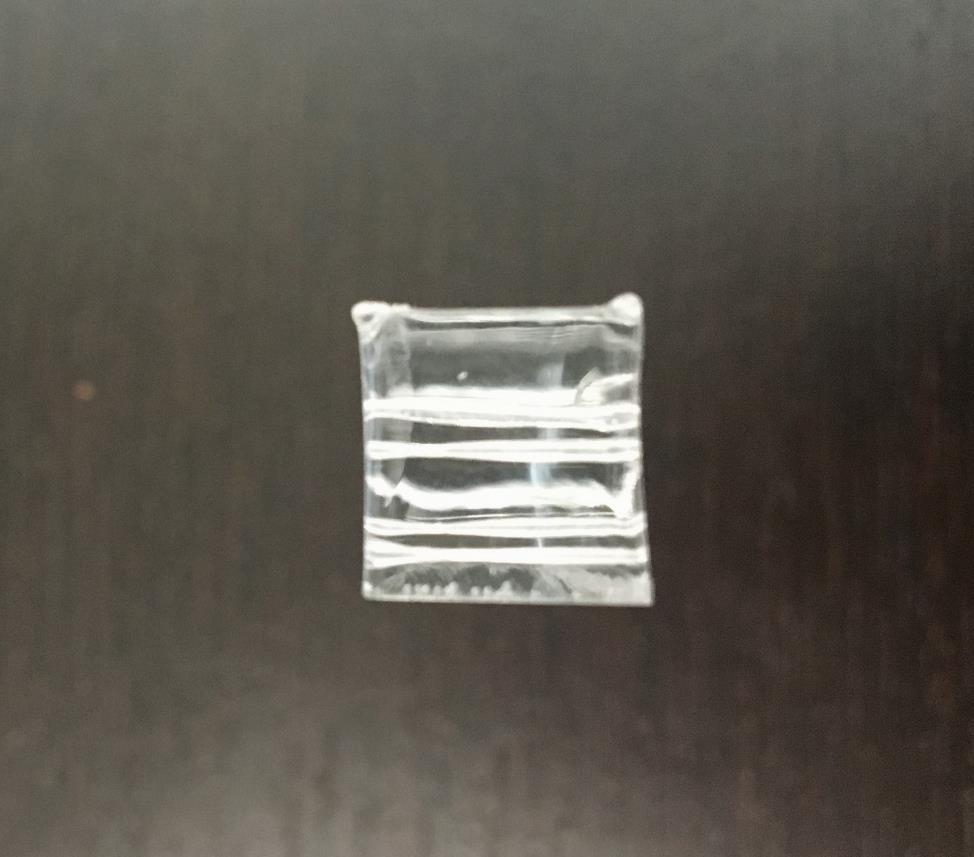
12 Pulse into the acrylic from the front Pulse into the acrylic from the side 12 B O S S L A S E R


13 As you can see in the picture below, the laser head was not perfectly aligned and the pulse was going into the acrylic at an angle. This is an example of what we don t want to happen. Alignment process starting at the mirror one and the laser tube If you have gone through and done the four-corner test and the vertical alignment and feel that the alignment on your machine is still off, the first step that you would take to make your adjustments and see exactly where you are hitting would be to put tape on mirror one and pulse your laser to see where exactly you are hitting on the first mirror. Your mirror one assembly is going to be right after the laser tube and is at the left-hand side of the machine, to get to this assembly, you are going to have to remove the panel that is on the outside of the mirror, it is held together with four screws. 1. Take the side panel off by removing the four screws 2. Double up your painter s tape 3. Apply the painters tape to mirror one, making a nice outline where the mirror would be 4. Lower power at control panel from 95% down to 25% 5. Hit the pulse button to get a dot burned onto the tape. 13 B O S S L A S E R


14 The mirror assembly located through the left side laser port View of burned dot after hitting pulse with tape on mirror one The picture above is how your pulse should look. It does not need to be perfectly centered but it should not be anywhere near the edges of the bracket at all. 14 B O S S L A S E R
 2.")
15 In event that the pulse that has been burned onto the tape for mirror one is not near the middle, and is hitting the edges of the bracket you would then have to adjust the glass tube. If the pulse on mirror one is too high or low you would, 1. Loosen the Allen screws on the tube bracket, (circled in red) 2. Turn the knob until the tube goes up or down, depending on your situation (circled in yellow) 3. Pulse onto the tape on mirror one, to verify that adjustments are good 4. Tighten down the Allen keys making sure the tube is exactly where you want it to be View of the brackets that hold the glass tube down The next step in the alignment process is to align from mirror one to two, to do this you would, 1. Pull the tape off mirror one 2. Double up the painters tape 3. Stick the tape onto mirror two making sure you get a nice indent of where the mirror is 4. Move the gantry to the back, making mirror two closest to mirror one 5. Pulse onto the tape 6. Move the gantry furthest away from mirror one 7. Pulse onto the tape 8. Make sure that the two pulses line up one on top of the other Sometimes you may not only have to move the laser tube up or down, you also may have to move the tube from right to left to line up on mirror one better. This would be a matter of loosening up the screws holding down the brackets and sliding the tube and tightening it back down, once satisfied with the results. 15 B O S S L A S E R

16 If the pulses do not line up one on top of the other you are going to have to adjust the gold knobs on the back of mirror one. Doing this is going to make sure that we have a solid beam profile throughout, no matter where the gantry is located. For help with how these adjustments work, see page 16. Results of pulsing onto mirror two In our case the first pulse was centered but a little bit to the left. We are going to want to make the second pulse match the first by making it go up and to the right. To get these two pulses to line up one on top of the other you will need to turn the gold knobs on the back of mirror one. These adjustments will be made with mirror two being furthest away from mirror one. 1. You would loosen the lock washers from the gold knobs on the bracket 2. Turn the top right knob counter clockwise, making the pulse go up, and then pulsing 3. Turn the bottom left knob clockwise, making the pulse go to the right, and then pulsing 4. OR you could move the bottom right knob (diagonal) counter clockwise to make it go up and to the right at the same time. 5. Pulse the laser to assure that one pulse is on top of the other 6. Tighten up the gold lock washers again making sure not to move the adjustment knobs *These adjustments were made in our case and may not necessarily reflect the adjustments that you will need to make* 16 B O S S L A S E R


17 Picture above shows how it should look with mirror two closest to mirror one Picture above shows how it should look with mirror two furthest away from mirror one 17 B O S S L A S E R

18 Results of making the adjustments on mirror one, solid beam profile After you have made the adjustments to the back of mirror one, your dot size should look like the picture above. The two pulses line up exactly on top of each other, which means wherever the gantry is located, the pulse will be the same throughout. When you have the beams lined up one on top of the other it does not need to be centered but it does need to be pretty close to the center. This is because pulsing at 25% power, the beam will be smaller for example, a pulse at 25% power will yield a dot size of maybe 5mm where as a pulse at 95% power will make the dot larger say about 10mm in size. You re going to want to make sure that your close to the center because it is possible that a pulse at 95% power will cause clipping on the edge of the mirror brackets. 18 B O S S L A S E R
 is your diagonal adjustment with counter clockwise making up go up and to the left and clockwise down and to the right.")
19 Adjustment knobs for mirror one and mirror two As you can see in the above photo the top right knob (green) is your up and down adjustments with turning counter clockwise making it go down and clockwise go up. The bottom right knob (blue) is your diagonal adjustment with counter clockwise making up go up and to the left and clockwise down and to the right. The bottom left knob (red) is your left to right adjustment, counter clockwise making it go right, and clockwise making it go left. These adjustments would be the same for the back of mirror two, and will only differ on the laser head itself. 19 B O S S L A S E R

20 Red dot pointer on the gen3 machines and up As you can see in the picture the laser has been equipped with a laser light. The laser light is only available on gen 3 and newer machines. Some older model lasers do not have these laser pointers at all. The key thing to remember with having a laser pointer is that if the laser pointer is off alignment it does not necessarily mean that the actual lasers pulse is out of alignment. The red dot pointer is a tool for you to use to make the alignment process easier. For example, if you know that you need your pulse to go to the right by 10mm, if you move the knobs and see that the red dot moved 10mm, the actual lasers pulse will reflect that change as well. Even if you do not have a red dot pointer to use you can still easily align your machine, the only difference being that you must make adjustments and pulse a lot more than what you would with having one. 20 B O S S L A S E R


21 After you pulse with the laser head closest and furthest your looking for a solid beam profile with the beam hitting dead center but a little high by about 1mm on the laser head. If you do not have a single dot size you would use the same steps used for aligning mirror one to two, but this time you would be moving the adjustment knobs on the back of mirror two. 21 B O S S L A S E R

22 Single dot size going into the laser head If you have a single dot size that is centered perfectly left to right but not up or down what you are going to do is loosen the two Allen screws and raise or lower the head depending on where the beam needs to go. If the beam is centered up and down and only needs to go either right or left you would loosen the four Allen keys on the top of the bracket where it attaches to the gantry and pull it to the left or right depending on the pulse. But remember, as mentioned earlier the beam needs to be a little high at about 1mm or so. 22 B O S S L A S E R
23 Adjustments on the laser head In event that your machine does not give you enough adjustment with the four Allen keys on the top of the laser head gantry bracket (green) you would then have to make the adjustment on the bracket of mirror two by loosening the two Allen screws and slide it either to the left or to the right. It is very crucial that you do not lose your 45 angle. To ensure that you can always get back to original position in case something goes wrong, we recommend scoring where the bracket sits so that you can see where it was originally positioned. *Moving mirror two is a last resort and we do not recommend it unless absolutely necessary* 23 B O S S L A S E R

24 Bracket adjustments on mirror two Like mentioned on the previous page, we do not recommend making any adjustments to this bracket whatsoever but in event that you must there are a few steps that can be taken to assure that we can go back to original position. The line colored in light blue would be a good place for you to take something sharp and drag across the metal to etch a groove into the metal so that you can see exactly where the original position was. When adjusting on this bracket try to be sure to keep the original 45-degree angle and only slide it either to the left or right by loosening the two screws circled in green. 24 B O S S L A S E R

25 Some useful things for you to remember while doing the alignment process: 1. Go through all the mirrors making sure that all the adjustment knobs have been tightened down using the inside gold lock washer. 2. Make sure that after doing the alignment that you go back through all the mirrors and clean them, including the lens in the laser head itself. Debris will get onto the mirrors while doing the alignment which could cause a loss of power. 3. After aligning your machine go back to your control panel and raise the max power back up to 95% 4. Put lines on all of the adjustment knobs so that you know where they were in event that something happens in the future. Mirror locking washers for the adjustment knobs The items highlighted in yellow are the locking washers for the adjustment knobs on the mirrors. Before tightening these down, it is best for you to make marks on the knobs where they are supposed to be set. When tightening these lock washers be sure to hold down on the knob, paying careful attention that the adjustment knob isn t moving by assuring the mark you made on them stays in the position that it is supposed to be in. 25 B O S S L A S E R

26 View of beam going into the laser head and nozzle As you can see in the above picture the beam is going down into the head perfectly aligned on both the 1 st and 3 rd diagram. The image in the middle is it being too high on mirror three. As the beam travels down into the laser head after it hits mirror three, it must be completely centered. This makes sure that you will not be clipping on the way down on the edges of the nozzle and it also ensures that you do not need to make too many adjustments on the gold knobs on the laser head itself. 26 B O S S L A S E R

27 Single dot size throughout machine This photo demonstrates what we are trying to achieve with the solid beam profile throughout the machine, with all the mirrors aligned and at a perfect 45-degree angle we will be getting a single dot size throughout. When we achieve a solid beam profile throughout the machine the laser strength is stronger and will be more concentrated going through the laser focal lens. This will give you the best results possible for both etching and cutting. 27 B O S S L A S E R

28 Single dot size down the center of the laser head and nozzle 28 B O S S L A S E R
Tools Needed 3/32 Allen Wrench which is located in your accessory kit Masking Tape
 Beam Alignment Overview Proper alignment of the beam is an important part of laser preventive maintenance. If the beam is out of alignment it is possible to lose power on the table, which will yield poor
Laser Alignment. Step-By-Step for the Epilog Mini / Helix Manufactured From 2004 to 2009 (8000 Model)
") Laser Alignment Step-By-Step for the Epilog Mini / Helix Manufactured From 2004 to 2009 (8000 Model) 1 Laser alignment can be done if any of the following applies to you. You are experiencing a general
Laser Alignment Step-By-Step for the Epilog Mini / Helix Manufactured From 2004 to 2009 (8000 Model) 1 Laser alignment can be done if any of the following applies to you. You are experiencing a general
Service Manual for XLE/XLT Series Laser Engravers
 Service Manual for XLE/XLT Series Laser Engravers Table of Contents Maintenance...1 Beam alignment...3 Auto focus alignment...8 Bridge alignment...10 Electronics panel replacement...11 X motor change...12
Laser Alignment Guide
 Laser Alignment Guide Once the laser has been installed, you must align it. The alignment procedure is very precise and delicate. It is important to understand how the alignment is done and why it must
Hubble Optics CDK 17 Collimation Instructions 03/27/2012 Hubble Optics
 Hubble Optics CDK 17 Collimation Instructions 03/27/2012 Hubble Optics 1: CDK17 Specification: System Effective Focal Length: 2894.7 mm, (this might be slightly different for different set of optics) Figure
7878 K940. Checkpoint Antenna. Kit Instructions. Issue B
 7878 K940 Checkpoint Antenna Kit Instructions Issue B Revision Record Issue Date Remarks A July 7, 2009 First issue B Nov2013 Revised the Checkpoint installation procedures for 7878 and 7874 scanners Added
Chevy Colorado. INSTALLATION GUIDE Front Bumper
 Chevy Colorado INSTALLATION GUIDE Front Bumper FIG 1A First, we ll start by removing the small allen bolts from the inside fender wells that hold the stock front bumper in place. FIG 1B You will also need
OPERATING INSTRUCTIONS for. Gold-Print TM. Model SPR-10 Screen and Stencil Printer
 OPERATING INSTRUCTIONS for Gold-Print TM Model SPR-10 Screen and Stencil Printer TABLE OF CONTENTS INSTALLATION...3 Z ADJUSTMENTS...3 X, Y & Ø ADJUSTMENTS...4 CIRCUIT BOARD POSITIONING...5 ILLUSTRATIONS...6
Replacing the build plate clamps
 Repair manual Replacing the build plate clamps Instructions The build plate clamps hold the glass plate in place on the heated bed. There are two fixed in place at the back of the heated bed and two at
EPILOG LASER Table Mountain Parkway Golden, Colorado Phone FAX
 EPILOG LASER 16371 Table Mountain Parkway Golden, Colorado 80403 Phone 303-215-9171 - FAX 303-277-9669 www.epiloglaser.com Machine Type: Zing Laser Engraver Procedure Title: Aligning the Laser Beam Tools
CordlessPRO Professional Wide Band Lift Sheet System
 CordlessPRO Professional Wide Band Lift Sheet System by: Safe-T-Shade 1. Construct your shade to the length and width desired. We suggest putting a stiffener in the bottom of hem of your shade such as
Using the Roller-Type Rotary attachment...
 Using the Roller-Type Rotary attachment... Our customer was very interested in purchasing our laser machine, and also interested in using the roller-style rotary attachment. **** Make sure the main door
DISCO DICING SAW SOP. April 2014 INTRODUCTION
 DISCO DICING SAW SOP April 2014 INTRODUCTION The DISCO Dicing saw is an essential piece of equipment that allows cleanroom users to divide up their processed wafers into individual chips. The dicing saw
INSTALLATION GUIDE 2009-CURRENT HUMMER H3T PRODUCT CODE:
 INSTALLATION GUIDE 2009-CURRENT HUMMER H3T PRODUCT CODE: 268 June 22, 2010 TOOLS NEEDED COMPONENTS INCLUDED P2 Tip 3/8" Drill Rubber Gasket(s) x 2 Bracket(s) x 2 1/2" Drill Bit Bulkhead Flange #2 Phillips
1503 Follow Spot Yoke, Source Four LED
 1503 Follow Spot Yoke, Source Four LED Rev 1.0 2016 City Theatrical, Inc. Getting Started with the City Theatrical Follow Spot Yoke for source four LED Congratulations on the purchase of your City Theatrical
ABM International, Inc. Navigator Assembly Manual
 ABM International, Inc. 1 1.0: Parts List Tablet (Qty. 1) Tablet mount (Qty. 1) NOTE: Mount may appear and operate different then image below Control Box (Qty. 1) Motor Power Supply (Qty. 1) 2 X-axis motor
Heavy Glass Frameless Shower Door With Return Panel
 202 Anderson Ave., Belvue, KS 66407 Phone: 800-669-9867 Fax: 800-393-6699 www.onyxcollection.com Heavy Glass Frameless Shower Door With Return Panel Full Showers with Return PL92-0118 R S K Parts List
1) Place the reactor stand on a sturdy bench with the bottom plate facing toward the front.
 Place the reactor stand on a sturdy bench with the bottom plate facing toward the front.") Assembly Instructions for ChemRxnHub Reactor Systems 1) Place the reactor stand on a sturdy bench with the bottom plate facing toward the front. Loosen knobs on the right and left using 2 hands of the
Assembly Instructions for ChemRxnHub Reactor Systems 1) Place the reactor stand on a sturdy bench with the bottom plate facing toward the front. Loosen knobs on the right and left using 2 hands of the
Using the RhAT II Universal
 Using the RhAT II Universal To use the Original RhAT Tools, the main shaft of the machine had to be rotated to the setting position, either mechanically or electronically, while the needle bar was disengaged
Fusion M2/32/40 focus, home and table calibration
 Fusion M2/32/40 focus, home and table calibration The purpose of this document is to provide step by step instructions for calibrating the focus gauge, auto-focus, table home, x-y home, squaring of vector
This manual will aid in the assembly of the FireBall V90 and FireBall X90. The assembly of both machines will be identical, unless specified.
 This manual will aid in the assembly of the FireBall V90 and FireBall X90. The assembly of both machines will be identical, unless specified. Step #1 Lay all parts out to verify quantities. (2) 2 x 25-1/4
Ender-3 3D Printer. Instructions for assembly
 Ender-3 3D Printer Instructions for assembly This guide is for the Ender-3 3D printer. Select the correct input voltage to match your local mains (220V or 110V). Because of software/hardware upgrades and
SAVE THESE INSTRUCTIONS
 SAVE THESE INSTRUCTIONS SONOMA 10.5 FT CANTILEVER UMBRELLA ASSEMBLY INSTRUCTIONS ASSEMBLE ON A FLAT, PROTECTED SURFACE. PART LIST FIGURE QUANTITY DESCRIPTION A LOWER BRACKET B UPPER BRACKET C BASE POLE
(2) 25mm x 20mm x 5mm Adhesive Backed Foam Pads. 100mm x 50mm x 1.0mm Adhesive Backed Foam. (2) Spacer Plates. Passenger/Right Side Frame Mounting
 25mm x 20mm x 5mm Adhesive Backed Foam Pads. 100mm x 50mm x 1.0mm Adhesive Backed Foam. (2) Spacer Plates. Passenger/Right Side Frame Mounting") PARTS LIST: 1 Grille Guard 10 12mm Lock Washers 1 Driver/Left Frame Mounting 16 12mm x 32mm OD x 3mm Flat Washers 1 Passenger/Right Frame Mounting 8 12mm Hex Nuts 1 Driver/Left Side Top Support 2 10-1.50mm
PARTS LIST: 1 Grille Guard 10 12mm Lock Washers 1 Driver/Left Frame Mounting 16 12mm x 32mm OD x 3mm Flat Washers 1 Passenger/Right Frame Mounting 8 12mm Hex Nuts 1 Driver/Left Side Top Support 2 10-1.50mm
Tools Needed Hardware Provided (per shade) Hardware Needed
 Hardware Needed") Baby Grande or Grande Motorized (XQ5 Premium) Shade with Cables and Housing Installation Instructions Tools Needed Hardware Provided (per shade) Hardware Needed Drill 3/8 Metal Drill Bit Measuring Tape
Baby Grande or Grande Motorized (XQ5 Premium) Shade with Cables and Housing Installation Instructions Tools Needed Hardware Provided (per shade) Hardware Needed Drill 3/8 Metal Drill Bit Measuring Tape
Removing the Z-Axis lead screw
 Page 1 of 8 TITLE: Sabre Z-Axis Lead Screw Replacement Procedure Gerber FastFact #: 5048 Supplied by: Gerber Hardware Support Last Modified: June 14, 2007 Summary: Tools used: The following procedure explains
Mount to the Wall INSTALLATION MANUAL
 Mount to the Wall 15 Locate the Wooden Studs This step applies to wooden stud wall installation only. Determine and mark the exact locations of two stud centers on the wall. Wooden studs should be spaced
RPMSP Series Installation Guide
 RPMSP Series Installation Guide Contents 1. Overview... page 1 2. Unpacking the Projector...2 3. Projector Configuration...2 4. Projector Throw Distance and Mounting...9 5. Projection Lens Focus...9 6.
Frameless Fixed Panel Slider
 INSTALLATION INSTRUCTIONS Frameless Fixed Panel Slider QCI-5279 SINGLE ROLLER WITH ANTI-JUMP DOUBLE ROLLERS QCI5279 Rev Page Certified 08/09/6 Tools: To install your New Shower Enclosure, you may need
Jointer Table Adjustment Procedure (for jointers with parallelogram table action)
") Jointer Table Adjustment Procedure (for jointers with parallelogram table action) Note: The tables on these types of jointers are adjusted by means of eccentric bushings that are located at the four corners
Jointer Table Adjustment Procedure (for jointers with parallelogram table action) Note: The tables on these types of jointers are adjusted by means of eccentric bushings that are located at the four corners
MOTORIZED STANDARD SHADE WITH CABLES Installation Instructions
 Tools Needed Drill Measuring Tape Pencil 2 Level Plumb Line ¼ Masonry Drill Bit Hammer Linesmans Pliers Cable Cutters Phillips & Flat-Head Screw Driver 11/32 Socket or Open End Wrench 5/32 Allen Wrench
Replacing the Reciprocator on the SWF Compact Series Machine (601C and 1201C)
") Follow the instructions below to replace the reciprocator in the SWF Compact series machines. The tools required can be found in the tool kit that came with the machine. Preparation 1. First, place the
Follow the instructions below to replace the reciprocator in the SWF Compact series machines. The tools required can be found in the tool kit that came with the machine. Preparation 1. First, place the
PlaneWave CDK Telescope Instructions. Setting the spacing and collimation for the CDK14/17/20/24
 PlaneWave CDK Telescope Instructions Setting the spacing and collimation for the CDK14/17/20/24 Collimation and Secondary Spacing Procedure The CDK optical design has four optical elements shown in Figure
VisioGlide 100 System W4F Four doors 2 fixed, 2 sliding
 Balcony Systems 2011 Visio Glide W4-F Curved Sliding Doors 4 doors: 2 fixed, and 2 sliding Installation guide 1. Insert silicone into the two bottom corners before closing the frame. 1 2. Connect top and
Giraud Tool Company, Inc.
 Motor Upgrade for Gracey Trimmer This package is intended to allow the user to upgrade their Gracey trimmer with a higher rpm motor and convenience features not found in the production offering. This upgrade
SIMPLEX ELITE MAT CUTTER
 INSTRUCTION MANUAL MODEL 750-1 / 760-1 SIMPLEX ELITE MAT CUTTER INSTRUCTIONS AND OPERATION MANUAL 40 in (101 cm) mat cutting system with bevel & straight cutters, production stops, 27 in (68 cm) squaring
1 Removing The Screen Track, Screen and Screen Rollers Note: The screen remains in the track while the track is removed and/or installed.
 Sliding Door Screen and Screen Track Replacement Service Instruction These instructions apply to: Architect Series 12/2004-Current Designer Series 3/2005-Current Tools Required: #2 Phillips head screwdriver
WASP Extended Shuttle Fitting. Process Overview
 Process Overview Tools needed; metric Hex key set Remove Wasp Plate sealer from all power and pneumatic supplies; situate the unit on a clear work area for access. Ensure the Wasp plate sealer has cooled
EmagiKit. Privacy Pod Plus. Quiet. Easy. Affordable. INSTRUCTIONS ASSEMBLY
 EmagiKit Privacy Pod Plus Quiet. Easy. Affordable. INSTRUCTIONS ASSEMBLY DIMENSIONS AND COMPONENTS 47 47 Ceiling Unit 2-B 2-L 2-R Glass Door Corner Trim Door Handle 90 Adjustable Height Work Surface 1-B
PRS X-Axis E-Chain Installation For Tools with a 12 Z-Axis
 888-680-4466 ShopBotTools.com PRS X-Axis E-Chain Installation For Tools with a 12 Z-Axis This kit is compatible with PRS Shopbots that have an X-axis cutting area of 96 to 144. It is not immediately compatible
Frameless Fixed Panel Slider QCI5279
 Frameless Fixed Panel Slider QCI5279 F AB GLASS AND MIRROR www.fabglassandmirror.com Call: +1 888-474-2221 Fax: (614)-334-4919 Office Timing: 8:30-18:00 EST info@fabglassandmirror.com Frameless Fixed Panel
Rotary Fixture M/V/X CLASS LASER SYSTEMS. Installation and Operation Instructions
 Rotary Fixture M/V/X CLASS LASER SYSTEMS Installation and Operation Instructions 02/01/2000 Introduction The Rotary Fixture controls in the Printer Driver are used along with the optional Rotary Fixture
Installing Your Electronic Deadbolt
 Ultra Security Plus Electronic Deadbolt Installation Instructions http://www.hberger.com/video-gallery/electronic-deadbolt New Installation Lock Location Preparation (Skip this section if you door has
Metroboard Pulley Replacement Procedure
 Metroboard Pulley Replacement Procedure 1) Remove the two transmission cover screws (1/8 allen driver). Then remove the transmission cover. Note there is a split lock washer and flat washer as well, so
4 Position the Suntile to the x tile s position and mark the felt around the square box flange. Then remove the Suntile
 4 Position the Suntile to the x tile s position and mark the felt around the square box flange. Then remove the Suntile 5 Using a sharp bladed knife, cut through the felt from corner to corner in an x
TYGER GUARD. Parts List BEFORE INSTALLATION WARNING TG-GD6D /7. Tyger Guard. Tube Brackets (Bull Bar) passenger or driver side
 passenger or driver side") TYGER GUARD TM BEFORE INSTALLATION TG-GD6D60068 READ INSTRUCTIONS CAREFULLY BEFORE STARTING INSTALLATION. REMOVE CONTENTS FROM BOX AND VERIFY ALL PARTS ARE PRESENT. ASSISTANCE IS RECOMMENDED. CUTTING IS
TYGER GUARD TM BEFORE INSTALLATION TG-GD6D60068 READ INSTRUCTIONS CAREFULLY BEFORE STARTING INSTALLATION. REMOVE CONTENTS FROM BOX AND VERIFY ALL PARTS ARE PRESENT. ASSISTANCE IS RECOMMENDED. CUTTING IS
After the canopy hinge is square with the firewall and the nut plates are installed you can set up the hinge mounts. Start by clamping a 1/16 tongue
 Written by: Sean Cole September 19, 2008 When fitting the stiffener use 3/32 clecos to hold it in place, it makes a smaller hole and is easier to work with. Only use the amount needed to hold the stiffener
Mounting a BalanceBox 400 to a brick wall
 Unpack the BalanceBox 400 and remove the Wall frame cover and its bag of screws. Slide the cover out at the top. NOTE: the cover is NOT included with the BalanceBox 400H LOCK SCREW HOLE MOBILE STAND MOUNTING
SOCCER TABLE. Assembly Instructions
 Updated: 5/4/16 SOCCER TABLE Assembly Instructions Table of Contents Parts Identifier... 3 Hardware Identifier. 4 Table Assembly Instructions... 5 Table Assembly Pictures..... 6, 7, 8 2 Page Parts Identifier
Work Space Set-up. Slats will level the pipe during bending and help minimize twisting of the bow.
 Work Space Set-up Affix pipe bender to end of working surface Slats will level the pipe during bending and help minimize twisting of the bow. Make the slat height equal the distance from your work surface
Frameless Heavy Glass Door with Header
 INSTALLATION INSTRUCTIONS Frameless Heavy Glass Door with Header QCI5243 QCI5243 REV. 0 Page 1 Certified 06/16/16 Frameless Heavy Glass Door with Pivot Hinges ITEM NUMBER DESCRIPTION QUANTITY 1 DOOR GLASS
Removing outter components
 Y Axis Motor Replacement Replacing the Y axis motor is a process that requires the individual to be somewhat mechanically inclined and can follow detailed instructions. If any of the following steps are
SAM. Model: STV-C65 LCD Mobile Visualized Stand Instruction Manual. Weight Capacity: 1251bs / 56.7kg Suits LCD Flat Panel Display: 42"-55" Page 20
 SAM Model: STV-C65 LCD Mobile Visualized Stand Instruction Manual Weight Capacity: 1251bs / 56.7kg Suits LCD Flat Panel Display: 42"-55" 20 Step 6 LCD Mobile Lift Stand Model: STV-C65 Cable management
NEW. Perfect Fit Roller Blind System Measuring, assembly & fitting instructions
 NEW Perfect Fit Roller Blind System Measuring, assembly & fitting instructions Perfect Fit Roller Blind System Measuring, assembly & fitting instructions Clearance & seals Seal Check clearance around the
45 CUTTING HEAD TILE SAW-BLADE ALIGNMENT PROCEDURE
 The of the MK-770 may become misaligned with the Cutting Head of the Tile Saw over time. Should misalignment occur, perform the following steps to realign the Tile Saw. NOTE: If alignment problems are
Frameless Bypass Slider
 INSTALLATION INSTRUCTIONS Frameless Bypass Slider QCI-5301 Heavy Glass Bypass Slider with Exposed Rollers QCI5301 Rev 0 Page 1 Certified 11/1/2016 Tools: To install your New Shower Enclosure, you may need
Baby Grande or Grande Crank Shade with Cables and Housing Installation Instructions
 Baby Grande or Grande Crank Shade with Cables and Housing Installation Instructions Tools Needed Drill 3/8 Metal Drill Bit Screwdriver (Flat & Phillips) Measuring Tape Pencil 4 Level Plumb Line ¼ Masonry
Kai Installation Instructions
 Kai Installation Instructions Before Beginning Installation Read through the entire instruction thoroughly A minimum of 2 people are required for this assembly These instructions reflect typical assemblies;
Sentinel Series Cigar Humidor End Tables
 Sentinel Series Cigar Humidor End Tables Assembly Instructions Models: Sentinel 500, 1000 and 1500 Style: Contemporary SENTINEL ASSEMBLY INSTRUCTIONS Congratulations! You have purchased a superior cigar
Heavy-Duty Bypass Track System
 Heavy-Duty Bypass Track System Please Note: This track system must be installed with the screws going into a solid surface such as studs or a header. Due to the spacing of the holes on these Brackets,
Installing Brackets to Minimize Distortion in Your SMART Board 685ix Interactive Whiteboard System s Projected Image
 UX60-RFK-685 Installing Brackets to Minimize Distortion in Your SMART Board 685ix Interactive Whiteboard System s Projected Image Follow these instructions to install brackets on your SMART Board 685ix
Q-Zone Hoop-Frame. Assembly Instructions. Copyright July 11, 2018 Grace Company (Reproduction Prohibited) Version 1.8
 Version 1.8") Q-Zone Hoop-Frame Assembly Instructions Copyright July 11, 2018 Grace Company (Reproduction Prohibited) Version 1.8 Table of Contents Table of Contents... i Warranty... ii Parts List Box 1...iii Box 2...
Q-Zone Hoop-Frame Assembly Instructions Copyright July 11, 2018 Grace Company (Reproduction Prohibited) Version 1.8 Table of Contents Table of Contents... i Warranty... ii Parts List Box 1...iii Box 2...
INTERCOOLER UPGRADE INSTALLATION INSTRUCTIONS PART NUMBER D APPLICATION: F87 M2
 INTERCOOLER UPGRADE INSTALLATION INSTRUCTIONS PART NUMBER D330-0026 APPLICATION: 2016-17 F87 M2 Congratulations for being selective enough to use a Dinan Intercooler Upgrade Kit. We have spent many hours
INSTALLATION INSTRUCTIONS GRILLE GUARD 09-ON DODGE RAM PART #
 INSTALLATION INSTRUCTIONS GRILLE GUARD 09-ON DODGE RAM PART # PARTS LIST: Qty Description Qty Description 1 Grille Guard 8 12-1.75mm x 35mm Hex Bolts 2 Brackets (for trucks without 22 12mm x 30.1mm OD
Removing and Replacing the Y-truck
 Service Documentation Removing and Replacing the Y-truck To remove and replace the Y-truck you will need the following tools: 4mm Allen wrench 12mm stamped flat wrench #2 Phillips screwdriver (magnetic
PHYS 3153 Methods of Experimental Physics II O2. Applications of Interferometry
 Purpose PHYS 3153 Methods of Experimental Physics II O2. Applications of Interferometry In this experiment, you will study the principles and applications of interferometry. Equipment and components PASCO
DeckRail A Product of DeckRite LLC 3912 East Progress North Little Rock, AR Phone: (501) Fax: (501)
 Fax: (501)") Disclaimer: Deck Rail Glass Railing Installation Guide This guide is not intended to replace a trained professional installer. The drawings and instructions contained within are for demonstration purposes
Disclaimer: Deck Rail Glass Railing Installation Guide This guide is not intended to replace a trained professional installer. The drawings and instructions contained within are for demonstration purposes
Item # Thanks for shopping with Improvements!
 Thanks for shopping with Improvements! Hampshire -Door Cabinet Item #5505 To order, call -800-64- West Chester, OH 45069 Made in China PR-6 If you have questions regarding this product, call -800-64- Mon.-Fri.
SmartView Mounting Frame 3 Wide x 3 Deep Video Wall Display Installation Guide
 SmartView Mounting Frame 3 Wide x 3 Deep Video Wall Display Installation Guide WMK-034 This display kit mounts ViewSonic 46 Video Wall displays in a 3 wide by 3 deep landscape configuration. The frame
Low/High Tunnel Greenhouse Plans
 Low/High Tunnel Greenhouse Plans Tools Needed (See the complete list of Greenhouse Tools) Hacksaw or Reciprocating Saw Socket Wrench, Adjustable Wrench or Nut Drivers Electric Drill with Drill Bits Sledge
Code Product Qty 1 Top Vertex 3 2 Hot End Housing 1 3 Bottom Vertex 3 4 Print Platform Lock 3 5 End Stop Holder 3 6 Filament Feeder Motor Bracket 1 7
 List of Parts Code Product Qty 1 680mm Extrusion 3 2 Power Supply 1 3 240mm Extrusion 9 4 42mm Nema 17 Stepper Motor 3 5 Slider-Hotend Connecting Rod 6 6 48mm Nema 17 Stepper Motor 1 7 Linear Rail with
AM8 Printer A metal frame for your Anet A8 By Pheneeny v1.0 April 20, 2017
 AM8 Printer A metal frame for your Anet A8 By Pheneeny v1.0 April 20, 2017 Please read this entire document before printing parts or building this frame Disclaimer: This guide is for informational purposes
The Useless Machine. DIY Soldering Edition. Instruction Guide v0004
 The Useless Machine DIY Soldering Edition Instruction Guide v0004 TM For the best outcome, follow each step in order. We recommend reading this guide entirely before you get started. Tools required: Soldering
a.k.a. casegoods instructions
 a.k.a. casegoods instructions a a.k.a. workwall installation IMPORTANT NOTES Failure to install product according to installation instruction will result in loss of warranty. Tools required for assembly
HQ Precision-Glide Track Upgrade 2 Extension Kit for HQ Studio Frame Part# QF09750
 HQ Precision-Glide Track Upgrade 2 Extension Kit for HQ Studio Frame Part# QF09750 Important Note: Upgrading the track system on the HQ Studio Frame requires the use of this 2 Extension Kit (Part #QF09750),
Monaco Installation Guide - Surface Profiles
 v1 Page 1 Thank you for purchasing this Monaco shower screen. Please study these instructions carefully before assembly and installation and check all supplied parts immediately upon receipt. These instructions
RH-412 STEEL DOORS INSTALLATION INSTRUCTIONS
 RH-412 STEEL DOORS INSTALLATION INSTRUCTIONS By following the steps outlined below, the assembly, installation and adjustment of the steel doors, will be a simple process. Let s start with the Driver Side.
Queen Wingback Bed King Wingback Bed
 Parts and Hardware List A. Side Rails with Attachment Hooks 2 pcs B. Foot Rail 1 pc C. Head Rail 1 pc D. Center Support Slat 1 pc E. Leg Supports 3 pcs F. Support Slats 4 pcs G. Flat Washers 8 pcs H. Lock
PL-93. Frameless Door with Panel & Return. 202 Anderson Ave., Belvue, KS Phone: Fax:
 202 Anderson Ave., elvue, KS 66407 Phone: 800-669-9867 Fax: 800-393-6699 www.onyxcollection.com 800-643-1514 www.alumaxshowerdoor.com PL-93 Frameless Door with Panel & Return Full Showers with Return ench
STEP 1 : DESTROYER FRONT BUMPER INSTALL GATHER YOUR TOOLS AND LAY OUT YOUR PARTS... *shorty bumper to show hardware* Tools Required:
 DESTROYER FRONT BUMPER INSTALL JL STEP 1 : GATHER YOUR TOOLS AND LAY OUT YOUR PARTS... Tools Required: - Utility knife - 11/16 Deep socket - Ratchet - 11/16 Crescent wrench - Ratchet Extension - 1/4 socket
model tsa-sa48 Sliding Crosscut Table installation guide
 model tsa-sa48 Sliding Crosscut Table installation guide A Note About Color Variations Among Anodized Aluminum Components Congratulations on the purchase of this SawStop Sliding Crosscut Table. We at SawStop
Allegro Home Office Assembly Instructions. Tipping Restraint. Bun Foot W/ Leveler. 4 pcs.
 email: info@riverside-furniture.com Allegro Home Office Assembly Instructions Components and Hardware List Page 1 of 5 Made in China Shelf Pin Wood Shelf File Rod & Clips 1/2"Wood Screw A 16 pcs. B 4 pcs.
SHERLINE Lathe Digital Readout
 SHERLINE Lathe Digital Readout P/N 8200 (Inch), P/N 8260 (Metric) The Digital Readout in the modern machine shop Digital readouts are popular on full size machine tools because they make the life of a
BMW X5 OEM RUNNING BOARD PART#SBBW
 INSTALLATION INSTRUCTIONS 2014-2016 BMW X5 OEM RUNNING BOARD PART#SBBW-146-74 QTY HARDWARE 1 Driver Side OEM Running Board 1 Passenger Side OEM Running Board 8 Rivet Pin 1 Page Step 1: Verify all parts
7. Michelson Interferometer
 7. Michelson Interferometer In this lab we are going to observe the interference patterns produced by two spherical waves as well as by two plane waves. We will study the operation of a Michelson interferometer,
ASSEMBLY INSTRUCTIONS MANUAL
 PAGE 1 OF 9 RECOMMENDED TOOLS FOR ASSEMBLY: ALLEN WRENCH (INCLUDED) BOX WRENCH (INCLUDED) PHILLIPS SCREW DRIVER (NOT INCLUDED) PARTS IN CARTON: ALLEN WRENCH SCREWS (20 EACH) ROUND HEAD SCREWS (8 EACH)
BABY WOLF LOOM. Assembly Instructions for Knocked-Down Looms
 BABY WOLF LOOM Assembly Instructions for Knocked-Down Looms BEFORE YOU BEGIN Please read through the directions before beginning to assemble your loom. Unpack the loom parts carefully. Do not throw away
Band-Master ATS Nano Pneumatic Banding Tool Operating Instructions
 Band-Master ATS 601-118 Nano Pneumatic Banding Tool CONTENTS 601-118 Overview... 3 Safety.... 5 Initial Tool Set-up... 5 Regulator assembly mounting... 5 Attach tool head to regulator.... 6 Operating instructions...
PL-91. Frameless Door with Panel. 202 Anderson Ave., Belvue, KS Phone: Fax:
 202 Anderson Ave., Belvue, KS 66407 Phone: 800-669-9867 Fax: 800-393-6699 www.onyxcollection.com 800-643-1514 www.alumaxshowerdoor.com PL-91 Frameless Door with Panel Full Showers Bench Seat Showers PL91-0318
User Instructions Multiline Otter Scoreboard Caddy Assembly
 List of parts: User Instructions Multiline Otter Scoreboard Caddy Assembly Single Caddy Double Caddy 1 1 Base assembly with attached wheels 2 4 1 1 2 4 4 8 10 20 12 Uprights (60 or 74 aluminum extrusion)
Step 1: Gather your parts!
 Step 1: Gather your parts! Show All Items The #mearm was designed with economy in mind. It is understood that laser cutters aren't the most common tools but there are more of them out there now than
Retractable Tongue Kit Model MPG457 Instructions
 Malone MicroSport Trailer Retractable Tongue Kit Model MPG457 Instructions TM Take a few moments and read through these instructions to familiarize yourself with the step by step assembly process before
Installation and Assembly: In-wall Mount for 32" to 71" Flat Panel Displays
 Installation and Assembly: In-wall Mount for 32" to 71" Flat Panel Displays Model# Display size range IM760P, IM760P-S 32" to 71" (81 to 180 cm) IM760PU, IM760PU-S 32" to 65" (81 to 165 cm) This product
Shapeoko XXL Assembly Guide
 Shapeoko XXL Assembly Guide 04/27/2016 XXL Packing LIst Item Qty Description Y-Carriage (left) 1 Y-Carriage (right) 1 X/Z Assembly 1 40 Rail 3 1 rail has mounting holes for controller Wasteboard Half 2
Frameless Bypass Slider
 INSTALLATION INSTRUCTIONS Frameless Bypass Slider QCI-5301 3/8 or 1/4 Glass Bypass Slider with Exposed Rollers QCI5301 Rev 1 Page 1 Certified 6/5/2017 Tools: To install your New Shower Enclosure, you may
Rim-Lock Door Set Installation Instructions
 Rim-Lock Door Set Installation Instructions Let s get started Check Your Parts List Two Doorknobs with Set Screws B. Doorknob Spindle C. Rim Lock with Mounting Screws D. Keeper with Mounting Screws E.
Panosaurus Rex. May Please Visit To view the setup video for the Panosaurus Rex.
 Panosaurus Rex May 2009 Please Visit http://gregwired.com/pano/support.htm To view the setup video for the Panosaurus Rex. Note: There currently is no printed setup information available. This booklet
Science Olympiad Optics LSS Tips and Tricks Alan Chalker September 2011
 Science Olympiad 2011-2012 Optics LSS Tips and Tricks Alan Chalker alan@chalker.org September 2011 NOTE: COMPETITORS ARE NOT REQUIRED TO BUILD AN LSS. EVENT SUPERVISORS WILL PROVIDE ONE DURING THE COMPETITION.
Interactive Monitor Arm
 Interactive Monitor Arm Tools Required -5mm Allen wrench -Phillips screwdriver -Plastic mallet There are two ways to attach a Monitor Arm to a Full Frame; with a Beam, or with a Post Mount. Both methods
STEINBERGER TRANSTREM (TYPE 2) TECHNICAL DOCUMENT
 TECHNICAL DOCUMENT") STEINBERGER TRANSTREM (TYPE 2) TECHNICAL DOCUMENT These instructions apply to newer style TransTrems only (non-threaded ball type or modified threaded ball type). For purposes of discussion, these TransTrems
STEINBERGER TRANSTREM (TYPE 2) TECHNICAL DOCUMENT These instructions apply to newer style TransTrems only (non-threaded ball type or modified threaded ball type). For purposes of discussion, these TransTrems