Solution of Exercises Lecture Optical design with Zemax for PhD Part 8
|
|
|
- Francis Marsh
- 5 years ago
- Views:
Transcription
1 Prof. Herbert Gross Friedrich Schiller University Jena Institute of Applied Physics Albert-Einstein-Str Jena Solution of Exercises Lecture Optical design with Zemax for PhD Part Multi configuration, universal plot and slider Load a classical achromate with a focal length of f = 100 mm, no field and numerical aperture NA = 0.1 from one of the vendor catalogs. Fix the wavelength to = nm. a) Add a thin mensicus shaped lens behind the system with an arteficial refractive index of n = 2 to enlarge the numerical aperture by a factor of 2 without introducing spherical aberration. To achieve this, the surfaces must be aplanatic and concentric. b) Now reduce the numerical aperture to a diameter of 2 mm and set a folding mirror in the front focal plane of the system. The incoming beam should be come from below and is deflected to the right side. c) Generate a multi-configuration system for a scan system by rotating the mirror. The first coordinate break angle can take the values -50, -47.5, -45, and -40. The second coordinate break should be defined by a pick up with a resulting bending angle of the system axis of -90. d) The chief ray of the scan system is telecentric in the paraxial approximation. Due to the residual aberrations of the system, there is a deviation from the telecentricity in the real system. Show this by a correponding universal plot. e) Show the variation of the spot in the image plane by using the slider. Solution: As a first step, the achromate AAP from the Mess Griot catalog is loaded. The field is set to zero, the aperture has a diameter of D = 20 and the wavelength is set to 546 nm. a) Two surfaces are added, the distances are chosen to be 1 and 2 mm. The first surface radius is taken as a solve to be aplanatic, the second to force the marginal ray angle to be THis corresponds to an aplanatic-concentric lens. Finally the image distance is optimized with the Quick focus menue. 1 / 12


2 2 In the Seidel bar menus it can be verified, that this lens does not introduce any spherical aberration. b) First the two radii of the mensiscus lens are frozen to be constant. Then the first distance is set to 0 and the cardinal points are calculated.


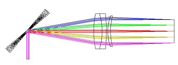
3 3 It is seen, that the front focal plane lies 46.8 mm in front of the system. The bending mirror is introduced in a corresponding distance.
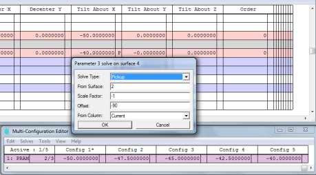
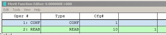
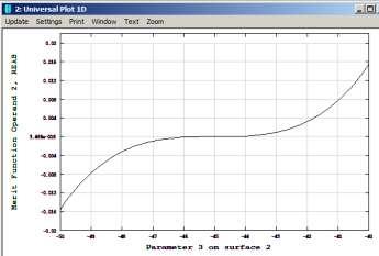
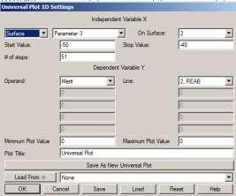
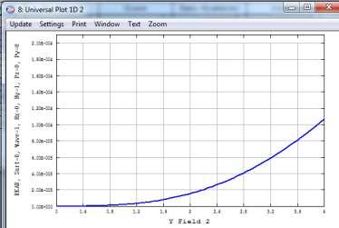
4 4 c) The multi-configuration is established as follows: d) The universal plot is generated with a REAB-operand in the merit function for the 1st configuration.
 Set")
 Introduce a Zernike surface on one side of the sample and make it visible in the interferogram.")
5 5 e) The spot diagram is used with dithered ray sampling and a fixed scale. The slider is configured as follows: 8.2 Multiconfiguration Interferometer 1 A Mach-Zehnder interferometer has the following principal geometry mirror sample beam combiner test arm detector source reference arm beam splitter mirror a) Set up a Mach-Zehnder interferometer as a multi configuration. The incoming beam should have a wavelength of = nm and is collimated with 10 mm diameter. The long sides of the interferometer are 100 mm long and the short ones 50 mm. b) Introduce a Zernike surface on one side of the sample and make it visible in the interferogram. As an axample, a spherical aberation of 5 th order (term No. 16 in Fringe nomenclature) with 1 coefficient should be used. c) Show the effect on the interferogram, if one mirror is shifted in a direction by 1 mm, which causes a lateral displacement of the test beam. What happens, if the combining mirror is tilted wrong by 0.1? What happens, if a tilt is set in the interferogramm settings? Solution: a) Setup of the interferometer:


6 6 b) On the front surface of the sample, a Zernike-Fringe type is introduced. In the reference arm, this surface is an air-to-air surface and therefore has no impact on the beam. The data of the surface can be view in the Extra Data Editor. A 16-term setup with normalizatrion radisu 5 mm is established, the coefficient is scaled in mm and therefore set to mm.

 A lateral shift between the two arms can be e.g.")


7 7 To view the Interferogram, the following settings are realized. It has to be noticed, that the reference wave is plane. Therefore in the General menue, the option 'Afocal Image Space' must be activated. c) A lateral shift between the two arms can be e.g. simulated by changing the vertical distance of the reference arm from 50 mm to 51 mm. Since the reference wave is plane, the interferogram is not changed. The lack of overlapping diameters, which occurs in practice, is not seen in Zemax. The same happens, if the beam combining mirror is tilted. It seems to be an error in the software, that a difference in beam position or orientation is not detected from the data. If a tilt is set in the wavefront / interferogram menue, the interferogram is changed dramatically due to a tilt overlay.

8 8 8.3 Universal plot for 4f-System Telecentricity Establish a generalized 4-f-optical system with the achromatic lens LAL from the catalog of CVI Melles and Griot with focal length f 1 =50 mm as front lens and LAL with f 2 = 200 mm as a rear group. The wavelength should be 632 nm and the initial numerical aperture NA = 0.1. a) What is the numerical aperture in the image space? b) If the stop is located in the intermediate focal point, the system is both sided telecentric. If the object sided telecentricity is forced explicitely in Zemax, determine the residual telecentricity error in the image space as a function of the object field height between y = 0 and 4 mm as a universal plot. c) Generate a two-dimensional universal plot, which shows the spot rms-diameter in the image on axis as a function of the object distance and the image distance. The distances should be variied in a range of 10 mm in the object space and 20 mm in the image space. d) If the lens groups are turned around, the performance of the image is worse. Compare the two spot diameters of both configurations. What happens to the telecentricity criterion of b)? Solution The lens is loaded and reversed in orientation.the wavelength is set to 632 nm and the numerical aperture NA = 0.1. The cardinal point options gives the principal plane to be located mm inside the lens on the object side and mm on the image side. The focal length is exactly f = mm. Therefore in paraxial approximation, the first distance is chosen to be = mm and the distance to the back focal point mm. These distances can be checked by simple raytraces of the marginal and the chief ray. Second, the lenswith 200 mm focal length is inserted from the catalog. The the first principal plane is located mm inside the lens, the exact focal length is mm. Therefore the distance from the stop to the lens is mm. The second principal plane is located at mm, therefore the image distance is mm. Other possibilities to find the optimal distances can be: 1. Optimize by looking on the corresponding paraxial or real ray angle 2. Solve the chief ray intersection to be zero for the pupil location. In this case, Zemax needs one additional arteficial surface.


9 9 a) The maginification of the system is m = 4.00, the numerical aperture in the image space is 0.1/4 = b) The telecentricity is forced in Zemax in the general menue. The universal plot is configured as follows: The result of this calculation shows a residual telecentricity error of 1.8 mrad at the fullfield, the error grows approximately quadratic.

10 10 c) To get a 2D universal plot with teh diameter,m we first must build the function of the diameter out of the radius operand RSCH by multiplying it by a factor of 2. For thsi, we construct the following merit function Then the 2D universal plot is configured as follows The result is seen here. The interpretation of the figure is: We see a nearly linear quadratic variation of the spot size for a defocussing of the object or th eimage. Due to the magnification of 0.25, the depth of focus in the object and the image space differs by a factor of 1/16. Therefore the defocussing sensitivity for the image spave defocus along t7 is much smaller than the object defocussing dependence.

11 11 d) The spot diameter on axis is in the optimal configuration 25 m, in the reverted setup the diameter grows by a factor of 10 to 285 m. The telecentricity error is reduced to 0.1 mrad.
12 12
Solution of Exercises Lecture Optical design with Zemax Part 6
 2013-06-17 Prof. Herbert Gross Friedrich Schiller University Jena Institute of Applied Physics Albert-Einstein-Str 15 07745 Jena Solution of Exercises Lecture Optical design with Zemax Part 6 6 Illumination
Tutorial Zemax 8: Correction II
 Tutorial Zemax 8: Correction II 2012-10-11 8 Correction II 1 8.1 High-NA Collimator... 1 8.2 Zoom-System... 6 8.3 New Achromate and wide field system... 11 8 Correction II 8.1 High-NA Collimator An achromatic
Lens Design I Seminar 1
 Xiang Lu, Ralf Hambach Friedrich Schiller University Jena Institute of Applied Physics Albert-Einstein-Str 15 07745 Jena Lens Design I Seminar 1 Warm-Up (20min) Setup a single, symmetric, biconvex lens
Lens Design I Seminar 5
 Y. Sekman, X. Lu, H. Gross Friedrich Schiller University Jena Institute of Applied Physics Albert-Einstein-Str 15 07745 Jena Lens Design I Seminar 5 Exercise 5-1: PSF scaling (Homework) To check the Airy
Lens Design I. Lecture 5: Advanced handling I Herbert Gross. Summer term
 Lens Design I Lecture 5: Advanced handling I 2018-05-17 Herbert Gross Summer term 2018 www.iap.uni-jena.de 2 Preliminary Schedule - Lens Design I 2018 1 12.04. Basics 2 19.04. Properties of optical systems
Lens Design II Seminar 6 (Solutions)
") 2017-01-04 Prof. Herbert Gross Yi Zhong, Norman G. Worku Friedrich Schiller University Jena Institute of Applied Physics Albert-Einstein-Str 15 07745 Jena Lens Design II Seminar 6 (Solutions) 6.1. Correction
2017-01-04 Prof. Herbert Gross Yi Zhong, Norman G. Worku Friedrich Schiller University Jena Institute of Applied Physics Albert-Einstein-Str 15 07745 Jena Lens Design II Seminar 6 (Solutions) 6.1. Correction
Exercise 1 - Lens bending
 Exercise 1 - Lens bending Most of the aberrations change with the bending of a lens. This is demonstrated in this exercise. a) Establish a lens with focal length f = 100 mm made of BK7 with thickness 5
Solutions: Lens Design I Part 2. Exercise 2-1: Apertures, stops and vignetting
 2016-04-25 Prof. Herbert Gross Mateusz Oleszko, Norman G. Worku Friedrich Schiller University Jena Institute of Applied Physics Albert-Einstein-Str 15 07745 Jena Solutions: Lens Design I Part 2 Exercise
Exercises Advanced Optical Design Part 5 Solutions
 2014-12-09 Manuel Tessmer M.Tessmer@uni-jena.dee Minyi Zhong minyi.zhong@uni-jena.de Herbert Gross herbert.gross@uni-jena.de Friedrich Schiller University Jena Institute of Applied Physics Albert-Einstein-Str.
1.1 Singlet. Solution. a) Starting setup: The two radii and the image distance is chosen as variable.
 Starting setup: The two radii and the image distance is chosen as variable.") 1 1.1 Singlet Optimize a single lens with the data λ = 546.07 nm, object in the distance 100 mm from the lens on axis only, focal length f = 45 mm and numerical aperture NA = 0.07 in the object space.
1 1.1 Singlet Optimize a single lens with the data λ = 546.07 nm, object in the distance 100 mm from the lens on axis only, focal length f = 45 mm and numerical aperture NA = 0.07 in the object space.
Lens Design I. Lecture 5: Advanced handling I Herbert Gross. Summer term
 Lens Design I Lecture 5: Advanced handling I 2015-05-11 Herbert Gross Summer term 2015 www.iap.uni-jena.de 2 Preliminary Schedule 1 13.04. Basics 2 20.04. Properties of optical systrems I 3 27.05. Properties
Lens Design I. Lecture 3: Properties of optical systems II Herbert Gross. Summer term
 Lens Design I Lecture 3: Properties of optical systems II 205-04-8 Herbert Gross Summer term 206 www.iap.uni-jena.de 2 Preliminary Schedule 04.04. Basics 2.04. Properties of optical systrems I 3 8.04.
Lens Design I. Lecture 3: Properties of optical systems II Herbert Gross. Summer term
 Lens Design I Lecture 3: Properties of optical systems II 207-04-20 Herbert Gross Summer term 207 www.iap.uni-jena.de 2 Preliminary Schedule - Lens Design I 207 06.04. Basics 2 3.04. Properties of optical
Optical Design with Zemax
 Optical Design with Zemax Lecture 9: Advanced handling 2014-06-13 Herbert Gross Sommer term 2014 www.iap.uni-jena.de 2 Preliminary Schedule 1 11.04. Introduction 2 25.04. Properties of optical systems
Optical Design with Zemax
 Optical Design with Zemax Lecture : Correction II 3--9 Herbert Gross Summer term www.iap.uni-jena.de Correction II Preliminary time schedule 6.. Introduction Introduction, Zemax interface, menues, file
Tutorial Zemax 3 Aberrations
 Tutorial Zemax 3 Aberrations 2012-08-14 3 Aberrations 1 3.1 Exercise 3-1: Strehl ratio and geometrical vs Psf spot size... 1 3.2 Exercise 3-2: Performance of an achromate... 3 3.3 Exercise 3-3: Anamorphotic
Optical Design with Zemax for PhD - Basics
 Optical Design with Zemax for PhD - Basics Lecture 3: Properties of optical sstems II 2013-05-30 Herbert Gross Summer term 2013 www.iap.uni-jena.de 2 Preliminar Schedule No Date Subject Detailed content
Optical Design with Zemax for PhD
 Optical Design with Zemax for PhD Lecture 7: Optimization II 26--2 Herbert Gross Winter term 25 www.iap.uni-jena.de 2 Preliminary Schedule No Date Subject Detailed content.. Introduction 2 2.2. Basic Zemax
Lens Design I. Lecture 10: Optimization II Herbert Gross. Summer term
 Lens Design I Lecture : Optimization II 5-6- Herbert Gross Summer term 5 www.iap.uni-jena.de Preliminary Schedule 3.. Basics.. Properties of optical systrems I 3 7.5..5. Properties of optical systrems
Lens Design I. Lecture 10: Optimization II Herbert Gross. Summer term
 Lens Design I Lecture : Optimization II 8-6- Herbert Gross Summer term 8 www.iap.uni-jena.de Preliminary Schedule - Lens Design I 8.4. Basics 9.4. Properties of optical systems I 3 6.4. Properties of optical
Tutorial Zemax Introduction 1
 Tutorial Zemax Introduction 1 2012-07-17 1 Introduction 1 1.1 Exercise 1-1: Stair-mirror-setup... 1 1.2 Exercise 1-2: Symmetrical 4f-system... 5 1 Introduction 1.1 Exercise 1-1: Stair-mirror-setup Setup
Advanced Lens Design
 Advanced Lens Design Lecture 3: Aberrations I 214-11-4 Herbert Gross Winter term 214 www.iap.uni-jena.de 2 Preliminary Schedule 1 21.1. Basics Paraxial optics, imaging, Zemax handling 2 28.1. Optical systems
Advanced Lens Design
 Advanced Lens Design Lecture 4: Optimization III 2013-11-04 Herbert Gross Winter term 2013 www.iap.uni-jena.de 2 Preliminary Schedule 1 15.10. Introduction Paraxial optics, ideal lenses, optical systems,
Exam Preparation Guide Geometrical optics (TN3313)
") Exam Preparation Guide Geometrical optics (TN3313) Lectures: September - December 2001 Version of 21.12.2001 When preparing for the exam, check on Blackboard for a possible newer version of this guide.
Exam Preparation Guide Geometrical optics (TN3313) Lectures: September - December 2001 Version of 21.12.2001 When preparing for the exam, check on Blackboard for a possible newer version of this guide.
Introduction to Optical Modeling. Friedrich-Schiller-University Jena Institute of Applied Physics. Lecturer: Prof. U.D. Zeitner
 Introduction to Optical Modeling Friedrich-Schiller-University Jena Institute of Applied Physics Lecturer: Prof. U.D. Zeitner The Nature of Light Fundamental Question: What is Light? Newton Huygens / Maxwell
Why is There a Black Dot when Defocus = 1λ?
 Why is There a Black Dot when Defocus = 1λ? W = W 020 = a 020 ρ 2 When a 020 = 1λ Sag of the wavefront at full aperture (ρ = 1) = 1λ Sag of the wavefront at ρ = 0.707 = 0.5λ Area of the pupil from ρ =
 Telecentric Imaging Object space telecentricity stop source: edmund optics The 5 classical Seidel Aberrations First order aberrations Spherical Aberration (~r 4 ) Origin: different focal lengths for different
Lens Design II. Lecture 2: Structural modifications Herbert Gross. Winter term
 Lens Design II Lecture 2: Structural modifications 26--26 Herbert Gross Winter term 26 www.iap.uni-jena.de 2 Preliminary Schedule 9.. Aberrations and optimization Repetition 2 26.. Structural modifications
OPTICAL IMAGING AND ABERRATIONS
 OPTICAL IMAGING AND ABERRATIONS PARTI RAY GEOMETRICAL OPTICS VIRENDRA N. MAHAJAN THE AEROSPACE CORPORATION AND THE UNIVERSITY OF SOUTHERN CALIFORNIA SPIE O P T I C A L E N G I N E E R I N G P R E S S A
Lecture 2: Geometrical Optics. Geometrical Approximation. Lenses. Mirrors. Optical Systems. Images and Pupils. Aberrations.
 Lecture 2: Geometrical Optics Outline 1 Geometrical Approximation 2 Lenses 3 Mirrors 4 Optical Systems 5 Images and Pupils 6 Aberrations Christoph U. Keller, Leiden Observatory, keller@strw.leidenuniv.nl
Tutorial Zemax 9: Physical optical modelling I
 Tutorial Zemax 9: Physical optical modelling I 2012-11-04 9 Physical optical modelling I 1 9.1 Gaussian Beams... 1 9.2 Physical Beam Propagation... 3 9.3 Polarization... 7 9.4 Polarization II... 11 9 Physical
Lecture 2: Geometrical Optics. Geometrical Approximation. Lenses. Mirrors. Optical Systems. Images and Pupils. Aberrations.
 Lecture 2: Geometrical Optics Outline 1 Geometrical Approximation 2 Lenses 3 Mirrors 4 Optical Systems 5 Images and Pupils 6 Aberrations Christoph U. Keller, Leiden Observatory, keller@strw.leidenuniv.nl
Lecture 4: Geometrical Optics 2. Optical Systems. Images and Pupils. Rays. Wavefronts. Aberrations. Outline
 Lecture 4: Geometrical Optics 2 Outline 1 Optical Systems 2 Images and Pupils 3 Rays 4 Wavefronts 5 Aberrations Christoph U. Keller, Leiden University, keller@strw.leidenuniv.nl Lecture 4: Geometrical
Lens Design II. Lecture 11: Further topics Herbert Gross. Winter term
 Lens Design II Lecture : Further topics 28--8 Herbert Gross Winter term 27 www.iap.uni-ena.de 2 Preliminary Schedule Lens Design II 27 6.. Aberrations and optimization Repetition 2 23.. Structural modifications
Lens Design II. Lecture 11: Further topics Herbert Gross. Winter term
 Lens Design II Lecture : Further topics 26--2 Herbert Gross Winter term 25 www.iap.uni-ena.de Preliminary Schedule 2 2.. Aberrations and optimization Repetition 2 27.. Structural modifications Zero operands,
Using Stock Optics. ECE 5616 Curtis
 Using Stock Optics What shape to use X & Y parameters Please use achromatics Please use camera lens Please use 4F imaging systems Others things Data link Stock Optics Some comments Advantages Time and
Optical Design with Zemax
 Optical Design with Zemax Lecture : Correction I 203-0-22 Herbert Gross Summer term 202 www.iap.uni-jena.de Preliminary time schedule 2 6.0. Introduction Introduction, Zemax interface, menues, file handling,
CATALOG LENS USE IN OSLO
 CATALOG LENS USE IN OSLO Tutorial: A Catalog Galilean Telescope Richard N. Youngworth, Ph.D. - Presenter Tutorial example: creating a Galilean telescope from catalog lenses Start a new lens, pick a name
Collimation Tester Instructions
 Description Use shear-plate collimation testers to examine and adjust the collimation of laser light, or to measure the wavefront curvature and divergence/convergence magnitude of large-radius optical
Optical Engineering 421/521 Sample Questions for Midterm 1
 Optical Engineering 421/521 Sample Questions for Midterm 1 Short answer 1.) Sketch a pechan prism. Name a possible application of this prism., write the mirror matrix for this prism (or any other common
Performance Factors. Technical Assistance. Fundamental Optics
 Performance Factors After paraxial formulas have been used to select values for component focal length(s) and diameter(s), the final step is to select actual lenses. As in any engineering problem, this
Optical Components for Laser Applications. Günter Toesko - Laserseminar BLZ im Dezember
 Günter Toesko - Laserseminar BLZ im Dezember 2009 1 Aberrations An optical aberration is a distortion in the image formed by an optical system compared to the original. It can arise for a number of reasons
Opti 415/515. Introduction to Optical Systems. Copyright 2009, William P. Kuhn
 Opti 415/515 Introduction to Optical Systems 1 Optical Systems Manipulate light to form an image on a detector. Point source microscope Hubble telescope (NASA) 2 Fundamental System Requirements Application
Sequential Ray Tracing. Lecture 2
 Sequential Ray Tracing Lecture 2 Sequential Ray Tracing Rays are traced through a pre-defined sequence of surfaces while travelling from the object surface to the image surface. Rays hit each surface once
EE119 Introduction to Optical Engineering Fall 2009 Final Exam. Name:
 EE119 Introduction to Optical Engineering Fall 2009 Final Exam Name: SID: CLOSED BOOK. THREE 8 1/2 X 11 SHEETS OF NOTES, AND SCIENTIFIC POCKET CALCULATOR PERMITTED. TIME ALLOTTED: 180 MINUTES Fundamental
Section 3. Imaging With A Thin Lens
 3-1 Section 3 Imaging With A Thin Lens Object at Infinity An object at infinity produces a set of collimated set of rays entering the optical system. Consider the rays from a finite object located on the
CHAPTER 1 Optical Aberrations
 CHAPTER 1 Optical Aberrations 1.1 INTRODUCTION This chapter starts with the concepts of aperture stop and entrance and exit pupils of an optical imaging system. Certain special rays, such as the chief
Lens Design II. Lecture 3: Aspheres Herbert Gross. Winter term
 Lens Design II Lecture 3: Aspheres 6-- Herbert Gross Winter term 6 www.iap.uni-jena.de Preliminar Schedule 9.. Aberrations and optimiation Repetition 6.. Structural modifications Zero operands, lens splitting,
Cardinal Points of an Optical System--and Other Basic Facts
 Cardinal Points of an Optical System--and Other Basic Facts The fundamental feature of any optical system is the aperture stop. Thus, the most fundamental optical system is the pinhole camera. The image
GEOMETRICAL OPTICS AND OPTICAL DESIGN
 GEOMETRICAL OPTICS AND OPTICAL DESIGN Pantazis Mouroulis Associate Professor Center for Imaging Science Rochester Institute of Technology John Macdonald Senior Lecturer Physics Department University of
Design and Correction of optical Systems
 Design and Correction of optical Sstems Part 5: Properties of Optical Sstems Summer term 2012 Herbert Gross Overview 2 1. Basics 2012-04-18 2. Materials 2012-04-25 3. Components 2012-05-02 4. Paraxial
ECEN 4606, UNDERGRADUATE OPTICS LAB
 ECEN 4606, UNDERGRADUATE OPTICS LAB Lab 2: Imaging 1 the Telescope Original Version: Prof. McLeod SUMMARY: In this lab you will become familiar with the use of one or more lenses to create images of distant
Simulation of Zernike Aberrations in optical systems. Michael Koch, July 5, 2018
 Simulation of Zernike Aberrations in optical systems Michael Koch, astroelectronic@t-online.de July 5, 2018 This paper is about three related questions: 1. In a Newton telescope we have two mirrors. It's
Long Wave Infrared Scan Lens Design And Distortion Correction
 Long Wave Infrared Scan Lens Design And Distortion Correction Item Type text; Electronic Thesis Authors McCarron, Andrew Publisher The University of Arizona. Rights Copyright is held by the author. Digital
Geometric optics & aberrations
 Geometric optics & aberrations Department of Astrophysical Sciences University AST 542 http://www.northerneye.co.uk/ Outline Introduction: Optics in astronomy Basics of geometric optics Paraxial approximation
Optical System Design
 Phys 531 Lecture 12 14 October 2004 Optical System Design Last time: Surveyed examples of optical systems Today, discuss system design Lens design = course of its own (not taught by me!) Try to give some
Tolerancing in Zemax. Lecture 4
 Tolerancing in Zemax Lecture 4 Objectives: Lecture 4 At the end of this lecture you should: 1. Understand the reason for tolerancing and its relation to typical manufacturing errors 2. Be able to perform
Converging Lenses. Parallel rays are brought to a focus by a converging lens (one that is thicker in the center than it is at the edge).
.") Chapter 30: Lenses Types of Lenses Piece of glass or transparent material that bends parallel rays of light so they cross and form an image Two types: Converging Diverging Converging Lenses Parallel rays
Chapter 30: Lenses Types of Lenses Piece of glass or transparent material that bends parallel rays of light so they cross and form an image Two types: Converging Diverging Converging Lenses Parallel rays
Chapter 3. Introduction to Zemax. 3.1 Introduction. 3.2 Zemax
 Chapter 3 Introduction to Zemax 3.1 Introduction Ray tracing is practical only for paraxial analysis. Computing aberrations and diffraction effects are time consuming. Optical Designers need some popular
AgilEye Manual Version 2.0 February 28, 2007
 AgilEye Manual Version 2.0 February 28, 2007 1717 Louisiana NE Suite 202 Albuquerque, NM 87110 (505) 268-4742 support@agiloptics.com 2 (505) 268-4742 v. 2.0 February 07, 2007 3 Introduction AgilEye Wavefront
Laboratory experiment aberrations
 Laboratory experiment aberrations Obligatory laboratory experiment on course in Optical design, SK2330/SK3330, KTH. Date Name Pass Objective This laboratory experiment is intended to demonstrate the most
PROCEEDINGS OF SPIE. Measurement of low-order aberrations with an autostigmatic microscope
 PROCEEDINGS OF SPIE SPIEDigitalLibrary.org/conference-proceedings-of-spie Measurement of low-order aberrations with an autostigmatic microscope William P. Kuhn Measurement of low-order aberrations with
Some lens design methods. Dave Shafer David Shafer Optical Design Fairfield, CT #
 Some lens design methods Dave Shafer David Shafer Optical Design Fairfield, CT 06824 #203-259-1431 shaferlens@sbcglobal.net Where do we find our ideas about how to do optical design? You probably won t
Beam expansion standard concepts re-interpreted
 Beam expansion standard concepts re-interpreted Ulrike Fuchs (Ph.D.), Sven R. Kiontke asphericon GmbH Stockholmer Str. 9 07743 Jena, Germany Tel: +49-3641-3100500 Introduction Everyday work in an optics
Introductions to aberrations OPTI 517
 Introductions to aberrations OPTI 517 Lecture 11 Spherical aberration Meridional and sagittal ray fans Spherical aberration 0.25 wave f/10; f=100 mm; wave=0.0005 mm Spherical aberration 0.5 wave f/10;
Computer exercise 2 geometrical optics and the telescope
 Computer exercise 2 geometrical optics and the telescope In this exercise, you will learn more of the tools included in Synopsys, including how to find system specifications such as focal length and F-number.
Optimisation. Lecture 3
 Optimisation Lecture 3 Objectives: Lecture 3 At the end of this lecture you should: 1. Understand the use of Petzval curvature to balance lens components 2. Know how different aberrations depend on field
Some of the important topics needed to be addressed in a successful lens design project (R.R. Shannon: The Art and Science of Optical Design)
") Lens design Some of the important topics needed to be addressed in a successful lens design project (R.R. Shannon: The Art and Science of Optical Design) Focal length (f) Field angle or field size F/number
Lens design Some of the important topics needed to be addressed in a successful lens design project (R.R. Shannon: The Art and Science of Optical Design) Focal length (f) Field angle or field size F/number
Lenses Design Basics. Introduction. RONAR-SMITH Laser Optics. Optics for Medical. System. Laser. Semiconductor Spectroscopy.
 Introduction Optics Application Lenses Design Basics a) Convex lenses Convex lenses are optical imaging components with positive focus length. After going through the convex lens, parallel beam of light
Conformal optical system design with a single fixed conic corrector
 Conformal optical system design with a single fixed conic corrector Song Da-Lin( ), Chang Jun( ), Wang Qing-Feng( ), He Wu-Bin( ), and Cao Jiao( ) School of Optoelectronics, Beijing Institute of Technology,
A tutorial for designing. fundamental imaging systems
 A tutorial for designing fundamental imaging systems OPTI 521 College of Optical Science University of Arizona November 2009 Abstract This tutorial shows what to do when we design opto-mechanical system
3.0 Alignment Equipment and Diagnostic Tools:
 3.0 Alignment Equipment and Diagnostic Tools: Alignment equipment The alignment telescope and its use The laser autostigmatic cube (LACI) interferometer A pin -- and how to find the center of curvature
Lecture 3: Geometrical Optics 1. Spherical Waves. From Waves to Rays. Lenses. Chromatic Aberrations. Mirrors. Outline
 Lecture 3: Geometrical Optics 1 Outline 1 Spherical Waves 2 From Waves to Rays 3 Lenses 4 Chromatic Aberrations 5 Mirrors Christoph U. Keller, Leiden Observatory, keller@strw.leidenuniv.nl Lecture 3: Geometrical
Microscopy. Lecture 2: Optical System of the Microscopy II Herbert Gross. Winter term
 Microscopy Lecture 2: Optical System of the Microscopy II 212-1-22 Herbert Gross Winter term 212 www.iap.uni-jena.de Preliminary time schedule 2 No Date Main subject Detailed topics Lecturer 1 15.1. Optical
Study on Imaging Quality of Water Ball Lens
 2017 2nd International Conference on Mechatronics and Information Technology (ICMIT 2017) Study on Imaging Quality of Water Ball Lens Haiyan Yang1,a,*, Xiaopan Li 1,b, 1,c Hao Kong, 1,d Guangyang Xu and1,eyan
Ch 24. Geometric Optics
 text concept Ch 24. Geometric Optics Fig. 24 3 A point source of light P and its image P, in a plane mirror. Angle of incidence =angle of reflection. text. Fig. 24 4 The blue dashed line through object
CHAPTER 33 ABERRATION CURVES IN LENS DESIGN
 CHAPTER 33 ABERRATION CURVES IN LENS DESIGN Donald C. O Shea Georgia Institute of Technology Center for Optical Science and Engineering and School of Physics Atlanta, Georgia Michael E. Harrigan Eastman
R.B.V.R.R. WOMEN S COLLEGE (AUTONOMOUS) Narayanaguda, Hyderabad.
 Narayanaguda, Hyderabad.") R.B.V.R.R. WOMEN S COLLEGE (AUTONOMOUS) Narayanaguda, Hyderabad. DEPARTMENT OF PHYSICS QUESTION BANK FOR SEMESTER III PAPER III OPTICS UNIT I: 1. MATRIX METHODS IN PARAXIAL OPTICS 2. ABERATIONS UNIT II
R.B.V.R.R. WOMEN S COLLEGE (AUTONOMOUS) Narayanaguda, Hyderabad. DEPARTMENT OF PHYSICS QUESTION BANK FOR SEMESTER III PAPER III OPTICS UNIT I: 1. MATRIX METHODS IN PARAXIAL OPTICS 2. ABERATIONS UNIT II
INTRODUCTION TO ABERRATIONS IN OPTICAL IMAGING SYSTEMS
 INTRODUCTION TO ABERRATIONS IN OPTICAL IMAGING SYSTEMS JOSE SASIÄN University of Arizona ШШ CAMBRIDGE Щ0 UNIVERSITY PRESS Contents Preface Acknowledgements Harold H. Hopkins Roland V. Shack Symbols 1 Introduction
CHARA Collaboration Review New York 2007 CHARA Telescope Alignment
 CHARA Telescope Alignment By Laszlo Sturmann Mersenne (Cassegrain type) Telescope M2 140 mm R= 625 mm k = -1 M1/M2 provides an afocal optical system 1 m input beam and 0.125 m collimated output beam Aplanatic
J. C. Wyant Fall, 2012 Optics Optical Testing and Testing Instrumentation
 J. C. Wyant Fall, 2012 Optics 513 - Optical Testing and Testing Instrumentation Introduction 1. Measurement of Paraxial Properties of Optical Systems 1.1 Thin Lenses 1.1.1 Measurements Based on Image Equation
Parity and Plane Mirrors. Invert Image flip about a horizontal line. Revert Image flip about a vertical line.
 Optical Systems 37 Parity and Plane Mirrors In addition to bending or folding the light path, reflection from a plane mirror introduces a parity change in the image. Invert Image flip about a horizontal
2.2 Wavefront Sensor Design. Lauren H. Schatz, Oli Durney, Jared Males
 Page: 1 of 8 Lauren H. Schatz, Oli Durney, Jared Males 1 Pyramid Wavefront Sensor Overview The MagAO-X system uses a pyramid wavefront sensor (PWFS) for high order wavefront sensing. The wavefront sensor
Waves & Oscillations
 Physics 42200 Waves & Oscillations Lecture 33 Geometric Optics Spring 2013 Semester Matthew Jones Aberrations We have continued to make approximations: Paraxial rays Spherical lenses Index of refraction
Imaging and Aberration Theory
 Imaging and Aberration Theory Lecture 7: Distortion and coma 2014-12-11 Herbert Gross Winter term 2014 www.iap.uni-jena.de 2 Preliminary time schedule 1 30.10. Paraxial imaging paraxial optics, fundamental
Mirrors and Lenses. Images can be formed by reflection from mirrors. Images can be formed by refraction through lenses.
 Mirrors and Lenses Images can be formed by reflection from mirrors. Images can be formed by refraction through lenses. Notation for Mirrors and Lenses The object distance is the distance from the object
PHYSICS FOR THE IB DIPLOMA CAMBRIDGE UNIVERSITY PRESS
 Option C Imaging C Introduction to imaging Learning objectives In this section we discuss the formation of images by lenses and mirrors. We will learn how to construct images graphically as well as algebraically.
GEOMETRICAL OPTICS Practical 1. Part I. BASIC ELEMENTS AND METHODS FOR CHARACTERIZATION OF OPTICAL SYSTEMS
 GEOMETRICAL OPTICS Practical 1. Part I. BASIC ELEMENTS AND METHODS FOR CHARACTERIZATION OF OPTICAL SYSTEMS Equipment and accessories: an optical bench with a scale, an incandescent lamp, matte, a set of
System/Prescription Data
 System/Prescription Data File : U:\alpi's designs\1.0 Meter\1.0 meter optical design\old Lenses- Design Stuff\LCOGT 1.0meter Telescope Design for UCSB.zmx Title: LCOGT 1.0 Meter Telescope Date : THU NOV
Lens Design II. Lecture 8: Special correction topics Herbert Gross. Winter term
 Lens Design II Lecture 8: Special correction topics 2018-12-12 Herbert Gross Winter term 2018 www.iap.uni-jena.de 2 Preliminary Schedule Lens Design II 2018 1 17.10. Aberrations and optimization Repetition
Chapter 18 Optical Elements
 Chapter 18 Optical Elements GOALS When you have mastered the content of this chapter, you will be able to achieve the following goals: Definitions Define each of the following terms and use it in an operational
NON-NULL INTERFEROMETER FOR TESTING OF ASPHERIC SURFACES. John J. Sullivan. A Dissertation Submitted to the Faculty of the COLLEGE OF OPTICAL SCIENCES
 NON-NULL INTERFEROMETER FOR TESTING OF ASPHERIC SURFACES by John J. Sullivan A Dissertation Submitted to the Faculty of the COLLEGE OF OPTICAL SCIENCES In Partial Fulfillment of the Requirements For the
Tangents. The f-stops here. Shedding some light on the f-number. by Marcus R. Hatch and David E. Stoltzmann
 Tangents Shedding some light on the f-number The f-stops here by Marcus R. Hatch and David E. Stoltzmann The f-number has peen around for nearly a century now, and it is certainly one of the fundamental
Chapter 23. Mirrors and Lenses
 Chapter 23 Mirrors and Lenses Notation for Mirrors and Lenses The object distance is the distance from the object to the mirror or lens Denoted by p The image distance is the distance from the image to
Chapter Ray and Wave Optics
 109 Chapter Ray and Wave Optics 1. An astronomical telescope has a large aperture to [2002] reduce spherical aberration have high resolution increase span of observation have low dispersion. 2. If two
OPAC 202 Optical Design and Inst.
 OPAC 202 Optical Design and Inst. Topic 9 Aberrations Department of http://www.gantep.edu.tr/~bingul/opac202 Optical & Acustical Engineering Gaziantep University Apr 2018 Sayfa 1 Introduction The influences
Aberrations of a lens
 Aberrations of a lens 1. What are aberrations? A lens made of a uniform glass with spherical surfaces cannot form perfect images. Spherical aberration is a prominent image defect for a point source on
Big League Cryogenics and Vacuum The LHC at CERN
 Big League Cryogenics and Vacuum The LHC at CERN A typical astronomical instrument must maintain about one cubic meter at a pressure of
Lecture 8. Lecture 8. r 1
 Lecture 8 Achromat Design Design starts with desired Next choose your glass materials, i.e. Find P D P D, then get f D P D K K Choose radii (still some freedom left in choice of radii for minimization
Optical design of a high resolution vision lens
 Optical design of a high resolution vision lens Paul Claassen, optical designer, paul.claassen@sioux.eu Marnix Tas, optical specialist, marnix.tas@sioux.eu Prof L.Beckmann, l.beckmann@hccnet.nl Summary: