Solutions: Lens Design I Part 2. Exercise 2-1: Apertures, stops and vignetting
|
|
|
- Madison Skinner
- 6 years ago
- Views:
Transcription

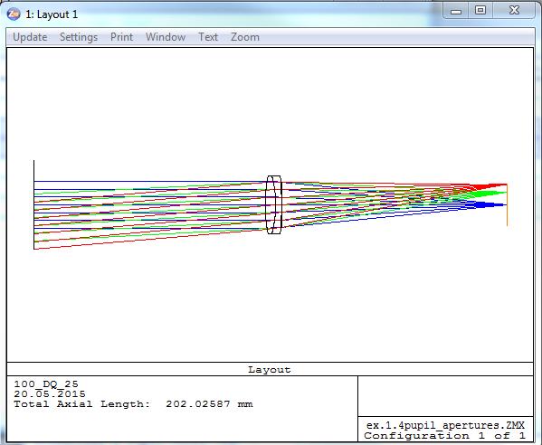
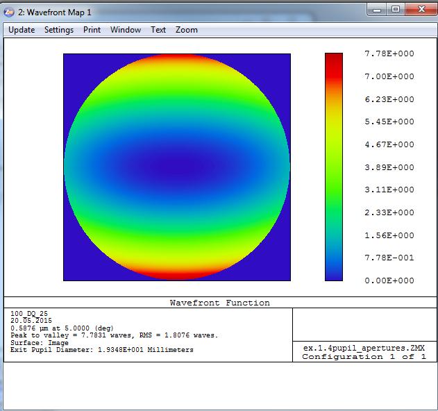
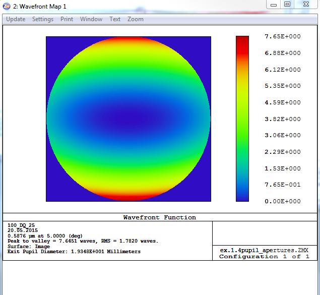
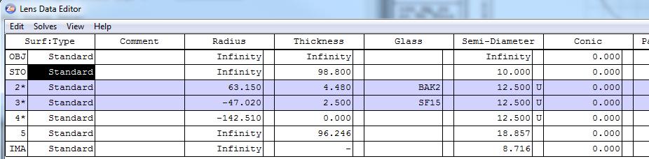
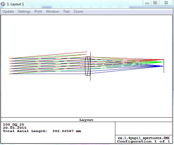
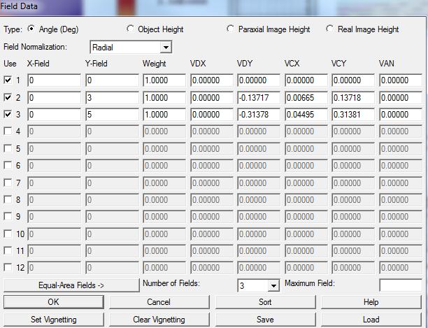
1 Prof. Herbert Gross Mateusz Oleszko, Norman G. Worku Friedrich Schiller University Jena Institute of Applied Physics Albert-Einstein-Str Jena Solutions: Lens Design I Part 2 Exercise 2-1: Apertures, stops and vignetting Load the achromate out of the lens catalog from the vendor Comar with a focal length f = 100mm called 100_DQ_25. Set the Entrance Pupil Diamter to EPD=20mm and insert the field points 0, 3 and 5. Vary the position of the stop. a) With the stop surface at the rear lens surface a. Generate the wavefront map without ray aiming b. Generate the wavefront map with ray aiming b) With the stop surface at the front focal plane Solution: a)a. a. Generate the wavefront map without vignetting b. Generate the wavefront map with vignetting
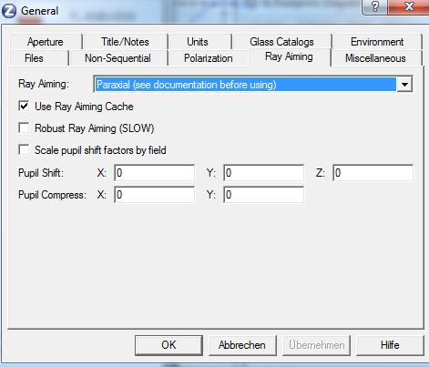
2 a)b.
3 b)a.

4 b)b. Open field and click set vignetting
 After a distance of 10 mm a second paraxial lens with focal length f2 = 30 mm fousses the ray.")


5 Exercise 2-2: Paraxial system layout a) Suppose a divergent ray bundle with numerical aperture of NA = 0.2 at the wavelength = 500 nm. Establish a first paraxial lens with a focal length to get a collimated beam with diameter 24 mm. b) After a distance of 10 mm a second paraxial lens with focal length f2 = 30 mm fousses the ray. Behind the focal point a third paraxial lens should collimated the beam again for a diameter of 36 mm. c) Now in a distance of 20 mm a foxussing oaraxial lens with focal lengt f = 100 is added. Finally a negative lens with f = -70 mm is added in an appropriate distance to change the numericalaperture in the image space to Find the final image distance. What ist the magnification of the system? Solution: a) Wavelength and numerical aperture are inserted. Then we set the focal length by a pickup to have the same value as the first object distance. This guarantees a collimated output beam. In the merit function a PARY value of D/2 = 12 mm is required, the first distance is variable. Alternatively without using the optimization, the value can be calculated by hand with tan(u) = sin(u)/cos(u) = D/2/f = mm or approximated with the slider. b) The 3rd lens must have a focal length of 36/24 x 30 = 45 mm. The air distances are correspondingly.


6 c) A second optimization selects the distance of lens 4 to obtain the numerical aperture by PARB to be The image distance is obtained by QUICK FOCUS. Thelens data ar The magnification is 0.2 / 0.05 = 4.


 Set the system in Zemax b) What is the spreading of the spectrum in the sensor plane?")
7 Exercise 2-3: Grating spectrometer A linear grating with a line density of 0.3 Lp/ m is illuminated by a collimated beam with a spectral broad wavelength between 400 nm and 700 nm. The grating is blazed and is used in the +1 st order. The spectrum is observed in a sensor plane, which is obtained after a symmetrical bi-convex lens with focal length f = 100 mm, a thickness of10 mm and SF6 as material in a telecentric arrangement. a) Set the system in Zemax b) What is the spreading of the spectrum in the sensor plane? Solution: a) System data and layout b) If a single raytrace is made for the extreme wavelengths 400 nm and 700 nm, one gets the ray heights in the sensor plane of mm and mm. Therefore the spectral spreading is y = mm.
 x y in normalized pupil coordinates and can be expressed by a superpostion of Zernike functions in the Fringe convention as W( x, y) 2 Z2 2 Z3 Z7")
8 Exercise 2-4: CPP expressed in Zernike polynomials A cubic phase plate can be used to enhance the depth of focus. It is described by the simple polynomial 3 3 W( x, y) x y in normalized pupil coordinates and can be expressed by a superpostion of Zernike functions in the Fringe convention as W( x, y) 2 Z2 2 Z3 Z7 Z8 Z10 Z11 4 a) Establish a simple system with an imcoming collimated beam at the wavelength = 546 nm, a diameter D = 7 mm and a focussing perfect lens of focal length f = 100 mm. A thin plane parallel plate of BK7 with thickness t = 5 mm is used as a phase plate. To get this functionality, one side is shaped as a Zernike surface according to the representation above with a normalization radius of 3.5 mm. The constant should be Visualize the surface contour of the cubic phase plate. b) Calculate the variation of the spot size over a defocus range of mm. Find the extended depth of focus, which should be defined as the interval, where the rms-spot is doubled in comparison to the best image plane. c) Calculate the shape of the spot in the best image plane and at a distance of z = 95 mm. What is observed? Calculate the MTF of the system in the surface representation for all azimuthal angles. What is the transfer behavior for different rotational settings of a bar pattern? d) Try to model the phase plate with another aspherical surface representation in Zemax. Solution: a) System with a Zernike Sag surface in Fringe convention with 11 terms, a normalization radius of 3.5 mm and the corresponding values. The user defined semi aperture in the lens datza editor should have teh same value as the normalization radius in the extra data editor. The surface sag is illustrated here:

.")
9 Comment: According to the manual, it is also possible to select the Zernike phase surface type. In this case, the substrate surface, where the ray deviation takes place, remains unchanged (plane). In the current case of small deviations, thisis equivalent. The scaling in this case is on the one side more complicated (a factor of 2 has to be taken into acount, the phase is scaled in radiant), on the other side, a common prefactor M can be used to scale the complete surface by changing only one number corresponding to the number in the above formula). b) By using a universal plot with the spot diameter as criterion, we get the two plots The minimum spot size is mm. The double value is obtained for z = 87 mm, therefore the depth of focus is 26 mm. c) The spot diagram in the best image plane at z = 100 mm and for z = 110 mm look as follows

10 The spot is quite large and is of triangular shape. There is only s small change in size for this defocussing. The MTF looks like the following figure. It is seen, that the transfer behavior is quite good for structures oriented along the x- and y-axis, but for rotated structures, the resolution is quite bad. d) The surface list offers an EXTENDED POLYNOMIAL surface, which in principle is a 2-dimensional Taylor expansion in x and y. This representation can be used to describe the cubic phase plate by


11 selecting a normalization radius of 5 mm and taking 9 terms. The coefficients X0Y3 and X3Y0 are chosen with the same coefficient The surface sag is identical to the model above.
Lens Design I Seminar 1
 Xiang Lu, Ralf Hambach Friedrich Schiller University Jena Institute of Applied Physics Albert-Einstein-Str 15 07745 Jena Lens Design I Seminar 1 Warm-Up (20min) Setup a single, symmetric, biconvex lens
Solution of Exercises Lecture Optical design with Zemax for PhD Part 8
 2013-06-17 Prof. Herbert Gross Friedrich Schiller University Jena Institute of Applied Physics Albert-Einstein-Str 15 07745 Jena Solution of Exercises Lecture Optical design with Zemax for PhD Part 8 8.1
Exercises Advanced Optical Design Part 5 Solutions
 2014-12-09 Manuel Tessmer M.Tessmer@uni-jena.dee Minyi Zhong minyi.zhong@uni-jena.de Herbert Gross herbert.gross@uni-jena.de Friedrich Schiller University Jena Institute of Applied Physics Albert-Einstein-Str.
Lens Design I Seminar 5
 Y. Sekman, X. Lu, H. Gross Friedrich Schiller University Jena Institute of Applied Physics Albert-Einstein-Str 15 07745 Jena Lens Design I Seminar 5 Exercise 5-1: PSF scaling (Homework) To check the Airy
Lens Design I. Lecture 3: Properties of optical systems II Herbert Gross. Summer term
 Lens Design I Lecture 3: Properties of optical systems II 205-04-8 Herbert Gross Summer term 206 www.iap.uni-jena.de 2 Preliminary Schedule 04.04. Basics 2.04. Properties of optical systrems I 3 8.04.
Solution of Exercises Lecture Optical design with Zemax Part 6
 2013-06-17 Prof. Herbert Gross Friedrich Schiller University Jena Institute of Applied Physics Albert-Einstein-Str 15 07745 Jena Solution of Exercises Lecture Optical design with Zemax Part 6 6 Illumination
Lens Design I. Lecture 5: Advanced handling I Herbert Gross. Summer term
 Lens Design I Lecture 5: Advanced handling I 2018-05-17 Herbert Gross Summer term 2018 www.iap.uni-jena.de 2 Preliminary Schedule - Lens Design I 2018 1 12.04. Basics 2 19.04. Properties of optical systems
Lens Design I. Lecture 3: Properties of optical systems II Herbert Gross. Summer term
 Lens Design I Lecture 3: Properties of optical systems II 207-04-20 Herbert Gross Summer term 207 www.iap.uni-jena.de 2 Preliminary Schedule - Lens Design I 207 06.04. Basics 2 3.04. Properties of optical
Tutorial Zemax 8: Correction II
 Tutorial Zemax 8: Correction II 2012-10-11 8 Correction II 1 8.1 High-NA Collimator... 1 8.2 Zoom-System... 6 8.3 New Achromate and wide field system... 11 8 Correction II 8.1 High-NA Collimator An achromatic
Optical Design with Zemax
 Optical Design with Zemax Lecture 9: Advanced handling 2014-06-13 Herbert Gross Sommer term 2014 www.iap.uni-jena.de 2 Preliminary Schedule 1 11.04. Introduction 2 25.04. Properties of optical systems
Exercise 1 - Lens bending
 Exercise 1 - Lens bending Most of the aberrations change with the bending of a lens. This is demonstrated in this exercise. a) Establish a lens with focal length f = 100 mm made of BK7 with thickness 5
1.1 Singlet. Solution. a) Starting setup: The two radii and the image distance is chosen as variable.
 Starting setup: The two radii and the image distance is chosen as variable.") 1 1.1 Singlet Optimize a single lens with the data λ = 546.07 nm, object in the distance 100 mm from the lens on axis only, focal length f = 45 mm and numerical aperture NA = 0.07 in the object space.
1 1.1 Singlet Optimize a single lens with the data λ = 546.07 nm, object in the distance 100 mm from the lens on axis only, focal length f = 45 mm and numerical aperture NA = 0.07 in the object space.
Lens Design II Seminar 6 (Solutions)
") 2017-01-04 Prof. Herbert Gross Yi Zhong, Norman G. Worku Friedrich Schiller University Jena Institute of Applied Physics Albert-Einstein-Str 15 07745 Jena Lens Design II Seminar 6 (Solutions) 6.1. Correction
2017-01-04 Prof. Herbert Gross Yi Zhong, Norman G. Worku Friedrich Schiller University Jena Institute of Applied Physics Albert-Einstein-Str 15 07745 Jena Lens Design II Seminar 6 (Solutions) 6.1. Correction
Tutorial Zemax 3 Aberrations
 Tutorial Zemax 3 Aberrations 2012-08-14 3 Aberrations 1 3.1 Exercise 3-1: Strehl ratio and geometrical vs Psf spot size... 1 3.2 Exercise 3-2: Performance of an achromate... 3 3.3 Exercise 3-3: Anamorphotic
Lens Design I. Lecture 5: Advanced handling I Herbert Gross. Summer term
 Lens Design I Lecture 5: Advanced handling I 2015-05-11 Herbert Gross Summer term 2015 www.iap.uni-jena.de 2 Preliminary Schedule 1 13.04. Basics 2 20.04. Properties of optical systrems I 3 27.05. Properties
Advanced Lens Design
 Advanced Lens Design Lecture 3: Aberrations I 214-11-4 Herbert Gross Winter term 214 www.iap.uni-jena.de 2 Preliminary Schedule 1 21.1. Basics Paraxial optics, imaging, Zemax handling 2 28.1. Optical systems
Optical Design with Zemax for PhD - Basics
 Optical Design with Zemax for PhD - Basics Lecture 3: Properties of optical sstems II 2013-05-30 Herbert Gross Summer term 2013 www.iap.uni-jena.de 2 Preliminar Schedule No Date Subject Detailed content
Optical Design with Zemax
 Optical Design with Zemax Lecture : Correction II 3--9 Herbert Gross Summer term www.iap.uni-jena.de Correction II Preliminary time schedule 6.. Introduction Introduction, Zemax interface, menues, file
Optical Design with Zemax for PhD
 Optical Design with Zemax for PhD Lecture 7: Optimization II 26--2 Herbert Gross Winter term 25 www.iap.uni-jena.de 2 Preliminary Schedule No Date Subject Detailed content.. Introduction 2 2.2. Basic Zemax
Tutorial Zemax Introduction 1
 Tutorial Zemax Introduction 1 2012-07-17 1 Introduction 1 1.1 Exercise 1-1: Stair-mirror-setup... 1 1.2 Exercise 1-2: Symmetrical 4f-system... 5 1 Introduction 1.1 Exercise 1-1: Stair-mirror-setup Setup
Lens Design I. Lecture 10: Optimization II Herbert Gross. Summer term
 Lens Design I Lecture : Optimization II 5-6- Herbert Gross Summer term 5 www.iap.uni-jena.de Preliminary Schedule 3.. Basics.. Properties of optical systrems I 3 7.5..5. Properties of optical systrems
Sequential Ray Tracing. Lecture 2
 Sequential Ray Tracing Lecture 2 Sequential Ray Tracing Rays are traced through a pre-defined sequence of surfaces while travelling from the object surface to the image surface. Rays hit each surface once
Chapter 3. Introduction to Zemax. 3.1 Introduction. 3.2 Zemax
 Chapter 3 Introduction to Zemax 3.1 Introduction Ray tracing is practical only for paraxial analysis. Computing aberrations and diffraction effects are time consuming. Optical Designers need some popular
Tutorial Zemax 9: Physical optical modelling I
 Tutorial Zemax 9: Physical optical modelling I 2012-11-04 9 Physical optical modelling I 1 9.1 Gaussian Beams... 1 9.2 Physical Beam Propagation... 3 9.3 Polarization... 7 9.4 Polarization II... 11 9 Physical
Lens Design I. Lecture 10: Optimization II Herbert Gross. Summer term
 Lens Design I Lecture : Optimization II 8-6- Herbert Gross Summer term 8 www.iap.uni-jena.de Preliminary Schedule - Lens Design I 8.4. Basics 9.4. Properties of optical systems I 3 6.4. Properties of optical
System/Prescription Data
 System/Prescription Data File : U:\alpi's designs\1.0 Meter\1.0 meter optical design\old Lenses- Design Stuff\LCOGT 1.0meter Telescope Design for UCSB.zmx Title: LCOGT 1.0 Meter Telescope Date : THU NOV
Tolerancing in Zemax. Lecture 4
 Tolerancing in Zemax Lecture 4 Objectives: Lecture 4 At the end of this lecture you should: 1. Understand the reason for tolerancing and its relation to typical manufacturing errors 2. Be able to perform
Some of the important topics needed to be addressed in a successful lens design project (R.R. Shannon: The Art and Science of Optical Design)
") Lens design Some of the important topics needed to be addressed in a successful lens design project (R.R. Shannon: The Art and Science of Optical Design) Focal length (f) Field angle or field size F/number
Lens design Some of the important topics needed to be addressed in a successful lens design project (R.R. Shannon: The Art and Science of Optical Design) Focal length (f) Field angle or field size F/number
Exam Preparation Guide Geometrical optics (TN3313)
") Exam Preparation Guide Geometrical optics (TN3313) Lectures: September - December 2001 Version of 21.12.2001 When preparing for the exam, check on Blackboard for a possible newer version of this guide.
Exam Preparation Guide Geometrical optics (TN3313) Lectures: September - December 2001 Version of 21.12.2001 When preparing for the exam, check on Blackboard for a possible newer version of this guide.
Lecture 4: Geometrical Optics 2. Optical Systems. Images and Pupils. Rays. Wavefronts. Aberrations. Outline
 Lecture 4: Geometrical Optics 2 Outline 1 Optical Systems 2 Images and Pupils 3 Rays 4 Wavefronts 5 Aberrations Christoph U. Keller, Leiden University, keller@strw.leidenuniv.nl Lecture 4: Geometrical
Computer exercise 2 geometrical optics and the telescope
 Computer exercise 2 geometrical optics and the telescope In this exercise, you will learn more of the tools included in Synopsys, including how to find system specifications such as focal length and F-number.
OPTICAL IMAGING AND ABERRATIONS
 OPTICAL IMAGING AND ABERRATIONS PARTI RAY GEOMETRICAL OPTICS VIRENDRA N. MAHAJAN THE AEROSPACE CORPORATION AND THE UNIVERSITY OF SOUTHERN CALIFORNIA SPIE O P T I C A L E N G I N E E R I N G P R E S S A
Opti 415/515. Introduction to Optical Systems. Copyright 2009, William P. Kuhn
 Opti 415/515 Introduction to Optical Systems 1 Optical Systems Manipulate light to form an image on a detector. Point source microscope Hubble telescope (NASA) 2 Fundamental System Requirements Application
Optical Design with Zemax for PhD
 Optical Design with Zemax for PhD Lecture 2: Basic Zemax handling 2015-12-02 Herbert Gross Winter term 2015 www.iap.uni-jena.de 2 Preliminar Schedule No Date Subject Detailed content 1 11.11. Introduction
Introduction to Optical Modeling. Friedrich-Schiller-University Jena Institute of Applied Physics. Lecturer: Prof. U.D. Zeitner
 Introduction to Optical Modeling Friedrich-Schiller-University Jena Institute of Applied Physics Lecturer: Prof. U.D. Zeitner The Nature of Light Fundamental Question: What is Light? Newton Huygens / Maxwell
Cardinal Points of an Optical System--and Other Basic Facts
 Cardinal Points of an Optical System--and Other Basic Facts The fundamental feature of any optical system is the aperture stop. Thus, the most fundamental optical system is the pinhole camera. The image
Optical Engineering 421/521 Sample Questions for Midterm 1
 Optical Engineering 421/521 Sample Questions for Midterm 1 Short answer 1.) Sketch a pechan prism. Name a possible application of this prism., write the mirror matrix for this prism (or any other common
Opto Engineering S.r.l.
 TUTORIAL #1 Telecentric Lenses: basic information and working principles On line dimensional control is one of the most challenging and difficult applications of vision systems. On the other hand, besides
Lens Design II. Lecture 3: Aspheres Herbert Gross. Winter term
 Lens Design II Lecture 3: Aspheres 6-- Herbert Gross Winter term 6 www.iap.uni-jena.de Preliminar Schedule 9.. Aberrations and optimiation Repetition 6.. Structural modifications Zero operands, lens splitting,
3.0 Alignment Equipment and Diagnostic Tools:
 3.0 Alignment Equipment and Diagnostic Tools: Alignment equipment The alignment telescope and its use The laser autostigmatic cube (LACI) interferometer A pin -- and how to find the center of curvature
OSLO Doublet Optimization Tutorial
 OSLO Doublet Optimization Tutorial This tutorial helps optical designers with the most basic process for setting up a lens and optimizing in OSLO. The example intentionally goes through basics as well
WaveMaster IOL. Fast and Accurate Intraocular Lens Tester
 WaveMaster IOL Fast and Accurate Intraocular Lens Tester INTRAOCULAR LENS TESTER WaveMaster IOL Fast and accurate intraocular lens tester WaveMaster IOL is an instrument providing real time analysis of
Lecture 2: Geometrical Optics. Geometrical Approximation. Lenses. Mirrors. Optical Systems. Images and Pupils. Aberrations.
 Lecture 2: Geometrical Optics Outline 1 Geometrical Approximation 2 Lenses 3 Mirrors 4 Optical Systems 5 Images and Pupils 6 Aberrations Christoph U. Keller, Leiden Observatory, keller@strw.leidenuniv.nl
Why is There a Black Dot when Defocus = 1λ?
 Why is There a Black Dot when Defocus = 1λ? W = W 020 = a 020 ρ 2 When a 020 = 1λ Sag of the wavefront at full aperture (ρ = 1) = 1λ Sag of the wavefront at ρ = 0.707 = 0.5λ Area of the pupil from ρ =
 Telecentric Imaging Object space telecentricity stop source: edmund optics The 5 classical Seidel Aberrations First order aberrations Spherical Aberration (~r 4 ) Origin: different focal lengths for different
OPAC 202 Optical Design and Inst.
 OPAC 202 Optical Design and Inst. Topic 9 Aberrations Department of http://www.gantep.edu.tr/~bingul/opac202 Optical & Acustical Engineering Gaziantep University Apr 2018 Sayfa 1 Introduction The influences
Using Stock Optics. ECE 5616 Curtis
 Using Stock Optics What shape to use X & Y parameters Please use achromatics Please use camera lens Please use 4F imaging systems Others things Data link Stock Optics Some comments Advantages Time and
Lens Design II. Lecture 2: Structural modifications Herbert Gross. Winter term
 Lens Design II Lecture 2: Structural modifications 26--26 Herbert Gross Winter term 26 www.iap.uni-jena.de 2 Preliminary Schedule 9.. Aberrations and optimization Repetition 2 26.. Structural modifications
Imaging and Aberration Theory
 Imaging and Aberration Theory Lecture 7: Distortion and coma 2014-12-11 Herbert Gross Winter term 2014 www.iap.uni-jena.de 2 Preliminary time schedule 1 30.10. Paraxial imaging paraxial optics, fundamental
Mechanical Tolerancing Results For the SALT/PFIS Collimator and Camera. January 24, 2003 J. Alan Schier
 Mechanical Tolerancing Results For the SALT/PFIS Collimator and Camera January 24, 2003 J. Alan Schier This report contains the tolerance information needed to produce a mechanical design for the SALT/PFIS
Lecture 2: Geometrical Optics. Geometrical Approximation. Lenses. Mirrors. Optical Systems. Images and Pupils. Aberrations.
 Lecture 2: Geometrical Optics Outline 1 Geometrical Approximation 2 Lenses 3 Mirrors 4 Optical Systems 5 Images and Pupils 6 Aberrations Christoph U. Keller, Leiden Observatory, keller@strw.leidenuniv.nl
Advanced Lens Design
 Advanced Lens Design Lecture 4: Optimization III 2013-11-04 Herbert Gross Winter term 2013 www.iap.uni-jena.de 2 Preliminary Schedule 1 15.10. Introduction Paraxial optics, ideal lenses, optical systems,
Use of Computer Generated Holograms for Testing Aspheric Optics
 Use of Computer Generated Holograms for Testing Aspheric Optics James H. Burge and James C. Wyant Optical Sciences Center, University of Arizona, Tucson, AZ 85721 http://www.optics.arizona.edu/jcwyant,
Computer Generated Holograms for Optical Testing
 Computer Generated Holograms for Optical Testing Dr. Jim Burge Associate Professor Optical Sciences and Astronomy University of Arizona jburge@optics.arizona.edu 520-621-8182 Computer Generated Holograms
Optimisation. Lecture 3
 Optimisation Lecture 3 Objectives: Lecture 3 At the end of this lecture you should: 1. Understand the use of Petzval curvature to balance lens components 2. Know how different aberrations depend on field
Design of Large Working Area F-Theta Lens. Gong Chen
 1 Design of Large Working Area F-Theta Lens by Gong Chen 2 ABSTRACT F-Theta lenses are different from normal camera lenses. It is one of the most important parts of laser scanning system. Besides, F-Theta
Optical Components for Laser Applications. Günter Toesko - Laserseminar BLZ im Dezember
 Günter Toesko - Laserseminar BLZ im Dezember 2009 1 Aberrations An optical aberration is a distortion in the image formed by an optical system compared to the original. It can arise for a number of reasons
Big League Cryogenics and Vacuum The LHC at CERN
 Big League Cryogenics and Vacuum The LHC at CERN A typical astronomical instrument must maintain about one cubic meter at a pressure of
ECEN 4606, UNDERGRADUATE OPTICS LAB
 ECEN 4606, UNDERGRADUATE OPTICS LAB Lab 2: Imaging 1 the Telescope Original Version: Prof. McLeod SUMMARY: In this lab you will become familiar with the use of one or more lenses to create images of distant
Study on Imaging Quality of Water Ball Lens
 2017 2nd International Conference on Mechatronics and Information Technology (ICMIT 2017) Study on Imaging Quality of Water Ball Lens Haiyan Yang1,a,*, Xiaopan Li 1,b, 1,c Hao Kong, 1,d Guangyang Xu and1,eyan
ECEN. Spectroscopy. Lab 8. copy. constituents HOMEWORK PR. Figure. 1. Layout of. of the
 ECEN 4606 Lab 8 Spectroscopy SUMMARY: ROBLEM 1: Pedrotti 3 12-10. In this lab, you will design, build and test an optical spectrum analyzer and use it for both absorption and emission spectroscopy. The
WaveMaster IOL. Fast and accurate intraocular lens tester
 WaveMaster IOL Fast and accurate intraocular lens tester INTRAOCULAR LENS TESTER WaveMaster IOL Fast and accurate intraocular lens tester WaveMaster IOL is a new instrument providing real time analysis
Lens Design II. Lecture 11: Further topics Herbert Gross. Winter term
 Lens Design II Lecture : Further topics 28--8 Herbert Gross Winter term 27 www.iap.uni-ena.de 2 Preliminary Schedule Lens Design II 27 6.. Aberrations and optimization Repetition 2 23.. Structural modifications
CATALOG LENS USE IN OSLO
 CATALOG LENS USE IN OSLO Tutorial: A Catalog Galilean Telescope Richard N. Youngworth, Ph.D. - Presenter Tutorial example: creating a Galilean telescope from catalog lenses Start a new lens, pick a name
Long Wave Infrared Scan Lens Design And Distortion Correction
 Long Wave Infrared Scan Lens Design And Distortion Correction Item Type text; Electronic Thesis Authors McCarron, Andrew Publisher The University of Arizona. Rights Copyright is held by the author. Digital
INFLUENCE OF VARIABLE APERTURE STOP
 INFLUENCE OF VARIABLE APERTURE STOP IN TELECENTRIC IMAGING LENSES SILL OPTICS GMBH CO. KG TECHNOLOGY FORUM MACHINE VISION 2015/16 Konrad Hentschel, Dipl-Phys. Andreas Platz, M.Sc. Project Management CONTENT
Magnification, stops, mirrors More geometric optics
 Magnification, stops, mirrors More geometric optics D. Craig 2005-02-25 Transverse magnification Refer to figure 5.22. By convention, distances above the optical axis are taken positive, those below, negative.
USE OF COMPUTER- GENERATED HOLOGRAMS IN OPTICAL TESTING
 14 USE OF COMPUTER- GENERATED HOLOGRAMS IN OPTICAL TESTING Katherine Creath College of Optical Sciences University of Arizona Tucson, Arizona Optineering Tucson, Arizona James C. Wyant College of Optical
October 7, Peter Cheimets Smithsonian Astrophysical Observatory 60 Garden Street, MS 5 Cambridge, MA Dear Peter:
 October 7, 1997 Peter Cheimets Smithsonian Astrophysical Observatory 60 Garden Street, MS 5 Cambridge, MA 02138 Dear Peter: This is the report on all of the HIREX analysis done to date, with corrections
Exam 4. Name: Class: Date: Multiple Choice Identify the choice that best completes the statement or answers the question.
 Name: Class: Date: Exam 4 Multiple Choice Identify the choice that best completes the statement or answers the question. 1. Mirages are a result of which physical phenomena a. interference c. reflection
ME 297 L4-2 Optical design flow Analysis
 ME 297 L4-2 Optical design flow Analysis Nayer Eradat Fall 2011 SJSU 1 Are we meeting the specs? First order requirements (after scaling the lens) Distortion Sharpness (diffraction MTF-will establish depth
Beam expansion standard concepts re-interpreted
 Beam expansion standard concepts re-interpreted Ulrike Fuchs (Ph.D.), Sven R. Kiontke asphericon GmbH Stockholmer Str. 9 07743 Jena, Germany Tel: +49-3641-3100500 Introduction Everyday work in an optics
Section A Conceptual and application type questions. 1 Which is more observable diffraction of light or sound? Justify. (1)
") INDIAN SCHOOL MUSCAT Department of Physics Class : XII Physics Worksheet - 6 (2017-2018) Chapter 9 and 10 : Ray Optics and wave Optics Section A Conceptual and application type questions 1 Which is more
INDIAN SCHOOL MUSCAT Department of Physics Class : XII Physics Worksheet - 6 (2017-2018) Chapter 9 and 10 : Ray Optics and wave Optics Section A Conceptual and application type questions 1 Which is more
Some lens design methods. Dave Shafer David Shafer Optical Design Fairfield, CT #
 Some lens design methods Dave Shafer David Shafer Optical Design Fairfield, CT 06824 #203-259-1431 shaferlens@sbcglobal.net Where do we find our ideas about how to do optical design? You probably won t
GEOMETRICAL OPTICS AND OPTICAL DESIGN
 GEOMETRICAL OPTICS AND OPTICAL DESIGN Pantazis Mouroulis Associate Professor Center for Imaging Science Rochester Institute of Technology John Macdonald Senior Lecturer Physics Department University of
Speed and Image Brightness uniformity of telecentric lenses
 Specialist Article Published by: elektronikpraxis.de Issue: 11 / 2013 Speed and Image Brightness uniformity of telecentric lenses Author: Dr.-Ing. Claudia Brückner, Optics Developer, Vision & Control GmbH
This experiment is under development and thus we appreciate any and all comments as we design an interesting and achievable set of goals.
 Experiment 7 Geometrical Optics You will be introduced to ray optics and image formation in this experiment. We will use the optical rail, lenses, and the camera body to quantify image formation and magnification;
Optical Design with Zemax
 Optical Design with Zemax Lecture : Correction I 203-0-22 Herbert Gross Summer term 202 www.iap.uni-jena.de Preliminary time schedule 2 6.0. Introduction Introduction, Zemax interface, menues, file handling,
Lens Design II. Lecture 11: Further topics Herbert Gross. Winter term
 Lens Design II Lecture : Further topics 26--2 Herbert Gross Winter term 25 www.iap.uni-ena.de Preliminary Schedule 2 2.. Aberrations and optimization Repetition 2 27.. Structural modifications Zero operands,
Chapter Ray and Wave Optics
 109 Chapter Ray and Wave Optics 1. An astronomical telescope has a large aperture to [2002] reduce spherical aberration have high resolution increase span of observation have low dispersion. 2. If two
Actually, you only need to design one monocular of the binocular.
 orro rism Binoculars Design a pair of 8X40 binoculars: Actually, you only need to design one monocular of the binocular. Specifications: Objective ocal Length = 200 mm Eye Relief = 15 mm The system stop
Phys 531 Lecture 9 30 September 2004 Ray Optics II. + 1 s i. = 1 f
 Phys 531 Lecture 9 30 September 2004 Ray Optics II Last time, developed idea of ray optics approximation to wave theory Introduced paraxial approximation: rays with θ 1 Will continue to use Started disussing
NON-NULL INTERFEROMETER FOR TESTING OF ASPHERIC SURFACES. John J. Sullivan. A Dissertation Submitted to the Faculty of the COLLEGE OF OPTICAL SCIENCES
 NON-NULL INTERFEROMETER FOR TESTING OF ASPHERIC SURFACES by John J. Sullivan A Dissertation Submitted to the Faculty of the COLLEGE OF OPTICAL SCIENCES In Partial Fulfillment of the Requirements For the
Testing Aspheric Lenses: New Approaches
 Nasrin Ghanbari OPTI 521 - Synopsis of a published Paper November 5, 2012 Testing Aspheric Lenses: New Approaches by W. Osten, B. D orband, E. Garbusi, Ch. Pruss, and L. Seifert Published in 2010 Introduction
CODE V Introductory Tutorial
 CODE V Introductory Tutorial Cheng-Fang Ho Lab.of RF-MW Photonics, Department of Physics, National Cheng-Kung University, Tainan, Taiwan 1-1 Tutorial Outline Introduction to CODE V Optical Design Process
Optical Design of an Off-axis Five-mirror-anastigmatic Telescope for Near Infrared Remote Sensing
 Journal of the Optical Society of Korea Vol. 16, No. 4, December 01, pp. 343-348 DOI: http://dx.doi.org/10.3807/josk.01.16.4.343 Optical Design of an Off-axis Five-mirror-anastigmatic Telescope for Near
Lenses Design Basics. Introduction. RONAR-SMITH Laser Optics. Optics for Medical. System. Laser. Semiconductor Spectroscopy.
 Introduction Optics Application Lenses Design Basics a) Convex lenses Convex lenses are optical imaging components with positive focus length. After going through the convex lens, parallel beam of light
PHY 431 Homework Set #5 Due Nov. 20 at the start of class
 PHY 431 Homework Set #5 Due Nov. 0 at the start of class 1) Newton s rings (10%) The radius of curvature of the convex surface of a plano-convex lens is 30 cm. The lens is placed with its convex side down
Finite conjugate spherical aberration compensation in high numerical-aperture optical disc readout
 Finite conjugate spherical aberration compensation in high numerical-aperture optical disc readout Sjoerd Stallinga Spherical aberration arising from deviations of the thickness of an optical disc substrate
The optical analysis of the proposed Schmidt camera design.
 The optical analysis of the proposed Schmidt camera design. M. Hrabovsky, M. Palatka, P. Schovanek Joint Laboratory of Optics of Palacky University and Institute of Physics of the Academy of Sciences of
CHAPTER 1 Optical Aberrations
 CHAPTER 1 Optical Aberrations 1.1 INTRODUCTION This chapter starts with the concepts of aperture stop and entrance and exit pupils of an optical imaging system. Certain special rays, such as the chief
Supplemental Materials. Section 25. Aberrations
 OTI-201/202 Geometrical and Instrumental Optics 25-1 Supplemental Materials Section 25 Aberrations Aberrations of the Rotationally Symmetric Optical System First-order or paraxial systems are ideal optical
06SurfaceQuality.nb Optics James C. Wyant (2012) 1
 1") 06SurfaceQuality.nb Optics 513 - James C. Wyant (2012) 1 Surface Quality SQ-1 a) How is surface profile data obtained using the FECO interferometer? Your explanation should include diagrams with the appropriate
06SurfaceQuality.nb Optics 513 - James C. Wyant (2012) 1 Surface Quality SQ-1 a) How is surface profile data obtained using the FECO interferometer? Your explanation should include diagrams with the appropriate
Conformal optical system design with a single fixed conic corrector
 Conformal optical system design with a single fixed conic corrector Song Da-Lin( ), Chang Jun( ), Wang Qing-Feng( ), He Wu-Bin( ), and Cao Jiao( ) School of Optoelectronics, Beijing Institute of Technology,
Katarina Logg, Kristofer Bodvard, Mikael Käll. Dept. of Applied Physics. 12 September Optical Microscopy. Supervisor s signature:...
 Katarina Logg, Kristofer Bodvard, Mikael Käll Dept. of Applied Physics 12 September 2007 O1 Optical Microscopy Name:.. Date:... Supervisor s signature:... Introduction Over the past decades, the number
EP 324 Applied Optics. Topic 3 Lenses. Department of Engineering of Physics Gaziantep University. Oct Sayfa 1
 EP 324 Applied Optics Topic 3 Lenses Department of Engineering of Physics Gaziantep University Oct 205 Sayfa PART I SPHERICAL LENSES Sayfa 2 Lens: The main instrument for image formation Sayfa 3 Lens A
Lens Design II. Lecture 8: Special correction topics Herbert Gross. Winter term
 Lens Design II Lecture 8: Special correction topics 2018-12-12 Herbert Gross Winter term 2018 www.iap.uni-jena.de 2 Preliminary Schedule Lens Design II 2018 1 17.10. Aberrations and optimization Repetition
Image Formation. Light from distant things. Geometrical optics. Pinhole camera. Chapter 36
 Light from distant things Chapter 36 We learn about a distant thing from the light it generates or redirects. The lenses in our eyes create images of objects our brains can process. This chapter concerns
Lens Design II. Lecture 3: Aspheres Herbert Gross. Winter term
 Lens Design II Lecture 3: Aspheres 7--3 Herbert Gross Winter term 7 www.iap.uni-jena.de Preliminar Schedule Lens Design II 7 6.. Aberrations and optimiation Repetition 3.. Structural modifications Zero
Optical design of a high resolution vision lens
 Optical design of a high resolution vision lens Paul Claassen, optical designer, paul.claassen@sioux.eu Marnix Tas, optical specialist, marnix.tas@sioux.eu Prof L.Beckmann, l.beckmann@hccnet.nl Summary: