Lensless diffractive imaging using tabletop, coherent, high harmonic soft x- ray beams
|
|
|
- Rosemary Hancock
- 5 years ago
- Views:
Transcription
1 Submitted to Physical Review Letters Lensless diffractive imaging using tabletop, coherent, high harmonic soft x- ray beams Richard L. Sandberg, Ariel Paul, Daisy Raymondson, Steffen Hädrich, David M. Gaudiosi, Jim Holtsnider, Ra anan I. Tobey, Oren Cohen, Margaret. M. Murnane and Henry C. Kapteyn JILA, University of Colorado and NSF Engineering Research Center in Extreme Ultraviolet Science and Technology, Boulder, CO 80309, USA Ph. (303) ; FAX (303) ; Changyong Song, Jianwei Miao Department of Physics, University of California, Los Angeles, California 90095, USA Yanwei Liu, Farhad Salmassi Center for X-ray Optics, Lawrence Berkeley National Laboratory, Berkeley, CA 94720, USA Abstract We present the first experimental demonstration of lensless diffractive imaging using coherent soft-x-rays generated by a tabletop soft-x-ray source. A 29 nm high harmonic beam illuminates an object, and the subsequent diffraction is collected on an x-ray CCD camera. High dynamic range diffraction patterns are obtained by taking multiple exposures while blocking small-angle diffraction using beam blocks of varying size. These patterns reconstruct to images with 200 nm resolution. This work demonstrates a practical tabletop lensless microscope that promises to find applications in materials science, nanoscience and biology. 1
2 For several centuries, microscopy has been a critical enabling technology in the understanding of materials and biological systems. Using innovative imaging and labeling techniques, visible light microscopes can image living cells with a resolution as high as 200 nm [1]. However, this resolution is fundamentally limited by the wavelength of visible/near-uv light. To further increase resolution, the much shorter wavelength of moderate-energy electrons can be used, and atomic level resolution has been demonstrated in electron microscopy [2]. However, electron microscopes are limited by the mean-free-path of the charged particles, and as a result this technique is restricted to imaging thin samples, typically < 500 nm. Many biological specimens, as well as samples of interest for materials science, are too thick for electron microscopy. Furthermore, low contrast in electron microscopy also requires sophisticated labeling techniques. Thus, new techniques for nano-microscopy are of great interest. One of the most promising alternative approaches for high-resolution imaging of thicker samples is to use shorter wavelength light, in the extreme ultraviolet (EUV) or soft-x-ray (SXR) regions of the spectrum [3]. EUV/SXR light can be used for nondestructive imaging applications requiring high resolution in thick samples [4]. Furthermore, numerous core-level absorption edges and widely varying elemental absorption cross sections provide excellent inherent image contrast, in particularly for biological imaging in the water window (300 ev 500 ev) region of the spectrum, or for magnetic domain imaging around 800 ev [3,5-6]. Successful soft-x-ray imaging techniques use diffractive or reflective optics such as Fresnel zone plates or multilayer mirrors, since the very strong absorption by matter and low index contrast of materials at short wavelengths precludes the use of refractive optics. Zone-plate imaging has been demonstrated at resolutions as high as 15 nm using state-of-the-art diffractive optics at synchrotron sources [7], 2
3 while zone plate imaging with tabletop high harmonic sources can achieve resolutions of 200 nm [8]. Zone plates require very careful manufacturing, with feature sizes equal to the desired resolution, and dimensional tolerances several times smaller than this. Furthermore, microscopes based on zone plate optics have a relatively short depth of field, commensurate with the very high resolution that can be attained. Lensless imaging is a relatively new coherent imaging technique that is complementary to zoneplate imaging [9-13]. This technique requires spatially coherent beams and eliminates imaging elements in the optical system by replacing them with a computerized phase retrieval algorithm. By obviating the need for an imaging system, lensless imaging is well-suited to x-rays, and was first demonstrated in 1999 using spatially-filtered light from a synchrotron source [9]. In lensless imaging, the x-ray beam illuminates an object, and the scatter pattern (diffracted light) from the object is collected on an x-ray CCD camera. For this technique to work, the diffraction pattern must be oversampled, i.e. the diffraction peaks coming from the highest spatial frequency of interest must be sampled at higher than the Nyquist criterion [14]. If a sharp diffraction pattern has been obtained and the oversampling requirement is met, the image can be reconstructed using iterative algorithms that retrieve both its amplitude and phase [15]. Given the need for coherent illumination of the sample, most small-scale EUV or x-ray sources are not suitable for lensless imaging. Thus, to-date, lensless imaging techniques have been the sole domain of large x-ray light source facilities such as synchrotrons or free-electron lasers, where the bright beams can be made spatially coherent by spatial filtering through very small pinholes. Very recently, the first lensless imaging using a soft-x-ray free-electron laser facility at 3
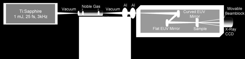
4 32 nm was demonstrated. In that work, the high per-pulse energy of the FEL allowed single shot diffraction data to be collected [16]. However, because the sample was destroyed in the process of acquiring the image, multiple exposures to increase the dynamic range of the data were not possible, and low spatial frequency information about the sample is missing. High harmonic generation in gas-filled waveguides generates spatially coherent EUV beams and is ideally suited for lensless imaging [17,18]. This light source has already been used for Gabor holography with resolution < 10 µm [17]. Although Gabor holography and lensless imaging are both coherent imaging techniques, geometric and flux considerations make lensless imaging better suited to high resolution imaging in a compact geometry. Here, we present the first experimental demonstration of lensless imaging using a tabletop source of coherent soft-x-rays. By taking multiple exposures while blocking small-angle scatter light using beam blocks of varying size, we obtain very high dynamic range diffraction patterns which successfully reconstruct to images with resolution near 200 nm. Moreover, no low spatial frequency information is missing from the reconstructions. This work thus demonstrates that lensless diffractive imaging can be successfully implemented using tabletop light sources, with broad potential application in nanoimaging and biological imaging. The set-up is shown in Fig. 1. In our experiment, 1.3 mj, 25 fs, femtosecond pulses from a Ti:sapphire laser amplifier system (KMLabs Dragon TM ) are focused into a gas-filled waveguide at intensities of 5x10 14 Wcm -2. Phase matching of the conversion process is achieved by pressure tuning the gas. In this regime, bright emission over a comb of odd-order harmonics from is obtained [19,20]. The hollow waveguide is a 150 µm inner-diameter, 10 cm long fused silica 4
5 capillary filled with argon gas at ~65 Torr pressure. When optimally coupled, an EUV beam is generated with a beam waist of about 25 µm and approximately 1 milliradian divergence, and a flux of ~10 12 photons per second in ~5 harmonics near 30 nm wavelength. Two 200 nm thick aluminum filters are used to eliminate the fundamental laser light, with the second being held in a specially designed light-tight fixture. A pair of narrowband, Mo/Si multilayer mirrors centered at ~29 nm acts as both a monochromator and a condenser, to gently focus the beam onto the sample with a beam diameter of a few hundred microns. The narrowband mirrors each have a reflectivity of 25% in a 2.5 nm bandpass, making it possible to effectively select a single harmonic order. The sample is held in an x-y stage controlled by high-precision closed-loop dc motors. The diffraction of the EUV light from the sample is recorded on a large-area x-ray CCD camera (Andor) with a 2048 x 2048 array of 13.5 µm pixels. Beam blocks of varying size are placed in the center of the diffraction pattern to block the more intense diffraction coming from low spatial frequencies. A large-diameter beam block (>1 mm diameter) allows us to acquire long exposure images to record the highest spatial frequencies diffracted from the sample, while a small beam block (<200 µm diameter) is used to record low spatial frequencies. These diffraction patterns are then stitched together, essentially extending the dynamic range of the camera from 5 to 15 orders of magnitude. These beam blocks are supported by a 12.5 µm wire tethered to a 2 diameter mounting ring, held in a kinematic x-y lens translator which has been retrofitted with two piezo stepper motors to allow fine control of the beam block position. Without the ability to accurately position the different beam blocks, the diffraction pattern would need to be steered onto the detector, compromising its consistency and complicating the image-stitching procedure. 5
6 A high quality and uniform soft-x-ray mode is needed for lensless imaging, to ensure the highest spatial coherence and sharpest diffraction data. Figure 1 shows the mode of the 29 nm beam after reflecting from the two multilayer mirrors. The mode profile fits to a near-perfect Gaussian, to the full dynamic range of the camera ( 10 4 ). The sample is carefully placed to optimize the illumination, diffraction quality, and oversampling ratio. The first consideration is to use high soft-x-ray flux on the sample, while still maintaining a flat intensity profile with a variation less than 10 percent. Overfilling the sample not only leads to a flatter intensity field, but also tends to ensure long-term illumination stability, mode quality, and a large radius of curvature of the softx-ray beam compared to the aperture size. The sample must be placed far enough from the detector to guarantee a far field diffraction pattern, given by z > 2 D!, where z is the sample to CCD distance, D is the sample diameter, λ is the wavelength. Finally, the distance from the sample to the CCD is chosen to give an appropriate linear oversampling ratio (> 5) that allows for easily reconstructable diffraction patterns with high resolution [21]. The linear oversampling ratio relates the smallest diffraction pattern speckles to CCD pixels. The linear oversampling ratio is given by z! O =, where z is the sample to CCD distance, λ is the wavelength, D is the pd sample diameter, and p is the pixel size of the CCD camera. For the two images described here, the linear oversampling ratios were ~10. In the reconstructed image, each image pixel (not to be confused with a CCD pixel), corresponds to a size d given by d z! =, where N is the number pn of pixels. This image pixel size is thus the ultimate resolution for any given geometry. Another limit on the resolution, r, of the reconstruction is the spectral bandwidth, λ/δλ of the source, 6
7 where OD r # [21]. By inspecting the speckle pattern at high scattering angles, we estimate! / "! that our spectral bandwidth is > 200. We used two objects for these initial experiments: a rectangular J aperture with a length of 80 µm, and a 15 µm diameter apertured section of a thin carbon foil with holes of various sizes ( Quantifoil Multi-A ). For the J object, the linear oversampling ratio was 9, with a sample to CCD distance z = 33 cm, and a sample size D = 80 µm. This results in an image resolution of ~1 µm. For the thin carbon film (~ 40 nm), the linear oversampling ratio was 13, with z = 9 cm and a sample size d = 15 µm. Figure 2(b) shows the coherent diffraction pattern from the J slit.. Three different diffraction patterns were stitched together to increase the dynamic range data. The lowest spatial frequencies were captured with no beam block in about 1 minute. Next, a small beam block, ~ 200 µm in diameter, was used to get slightly higher spatial frequencies in about 10 minutes. Finally, a larger beam block, ~3 mm in diameter, was used to capture the highest spatial frequencies in about 120 minutes. To reduce noise in the intensity of the final diffraction patterns, we applied the inverse Fourier transform to the measured intensity and obtained the autocorrelation function of the sample. Since the linear oversampling ratio is >> 2, the autocorrelation function is surrounded by a large region that should have no signal. However, because of camera noise that region is not exactly zero. We therefore applied a low-pass filter to force this region to be zero. We then numerically integrated the diffraction intensity by binning 3 3 pixels into 1 pixel and applying a deconvolution to remove the artifacts in the diffraction pattern due to intensity integration [22]. Only the central 2040 x 2040 pixels were used for this integration. This step significantly 7
8 enhanced the signal-to-noise ratio of the coherent diffraction pattern. The analyzed diffraction pattern has a linear oversampling ratio ~1/3 smaller than stated above and an array size of 680 x 680 pixels. This also eases the requirement on the temporal coherence by a factor of 3. Phase retrieval of the coherent diffraction pattern is carried out using the guided hybrid-inputoutput (GHIO) algorithm [22]. This algorithm starts with 16 independent reconstructions of the diffraction pattern, where random initial phases are used as the initial input. Each reconstruction iterates back and forth between real and reciprocal space. In real space, the sample density outside a support and the negative real or imaginary part of the electron density inside the support are slowly pushed to zero. The support is a rectangular shape with its size estimated from the linear oversampling ratio. In reciprocal space, the magnitude of the Fourier transform (i.e. square root of the diffraction intensity) remains unchanged, and the phase is updated with each iteration. After 2000 iterations, 16 images are reconstructed, which is defined as the 0 th generation. An R-value is calculated for each image based on the difference between the measured and calculated magnitude of Fourier transform. A seed image is then selected that corresponds to the image with the smallest R-value. By multiplying the seed with each of the 16 images and taking the square root of the product, a new set of 16 images is obtained, which is used as the initial inputs for the next generation. We repeat the procedure for the next generation, and after the 8 th generation, the 16 reconstructed images became consistent. Based on the reconstructed images, we define a tight support that represents the true envelope of the object. Using this tight support, we start with another GHIO run and obtain the final reconstructed image. Because the diffraction pattern is non-centro-symmetric, the electron density of the sample is complex, which in principle makes the phase retrieval more difficult than for real 8
9 objects. By using a tight support with GHIO, and imposing a positivity constraint on both the real and imaginary parts, we have shown that complex objects can be reliably reconstructed from oversampled diffraction patterns. Figure 2(c) shows the final image of the J pattern, with each pixel corresponding to 347 nm. This pattern was used as an initial test pattern as a proof of principle. The reconstructed image is consistent with the optical microscope image shown in Fig. 2(a). However, electron density noise can be seen in this image, arising from long-term instability of the EUV source and setup, and the finite spectral bandwidth of λ/δλ ~ 200 at 29 nm. When using narrow spectral bandwidth x- rays (λ/δλ ~ 7500) from synchrotron radiation sources, this effect is not observed. A lensless image of the carbon film, apertured to 15 µm, is shown in Fig. 3. Figure 3(a) is a SEM picture of the sample, and 3(b) shows the diffraction pattern. The non-centro-symmetry of the diffraction pattern indicates that the sample has absorption and that the sample density is complex. Figure 3(c) shows the magnitude of the density for the lensless image, which agrees well with the SEM image. The slight disagreement between the alignment of the holes in the SEM and lensless images is due to parallax. This arises because the carbon film and mounting aperture are separated by 56 µm. Thus, even a few degrees of tilt in the SEM stage slightly alters the parallax and the exact alignment of the smaller holes in the SEM image with respect to the large aperture. A line scan of the reconstructed image indicates that the current tabletop lensless microscope has a resolution of 214 nm. 9
10 Three approaches are possible for further improving the ultimate resolution of the microscope. First, if a larger detector were used, higher spatial frequencies could be captured while maintaining the oversampling ratio. Equivalently, a CCD camera with a smaller pixel size could be used, and the sample to CCD distance reduced. Second, the effective spectral bandwidth of the source could be improved using either narrower band mirrors or by narrowing the individual harmonic peaks. Third, shorter wavelength HHG light could be used. Techniques for selective enhancement of a single harmonic order, that can result in narrower bandwidths at shorter wavelengths have recently been demonstrated.[23-25] Such improvements will extend the ultimate resolution to tens of nm. As the laser repetition rates are increased from 3 khz to tens of khz, the soft-x-ray flux will be simultaneously increased, and image acquisition time will be dramatically reduced from hours to minutes. Also, as computing power increases and reconstruction times subsequently shrink, a tabletop soft-x-ray lensless microscope will become increasingly practical for routine use in biological imaging, nanoscience, and metrology in support of next-generation lithographies. Moreover, the femtosecond time resolution afforded by high harmonics will enable tabletop time-resolved imaging on femtosecond timescales. Several aspects of lensless imaging make it an extremely elegant and appealing technique. Our light source, while bright, does not compete with the overall flux available at a synchrotron or FEL facility. In our current setup, the integration time is 120 minutes. Ease of sample setup is thus an important concern, as well as the long-term stability of the light source. Because lensless imaging only requires illumination with a plane wave, placement of the sample is non-critical (~mm placement accuracy is sufficient in our geometry). No multi-step focusing process is necessary, as is the case for imaging optics where sample placement and stability at the micron 10
11 level are necessary. Furthermore, using imaging optics the magnification is a purely geometric function of the object to image distance ratio, often requiring the detector to be a meter or more from the imaging optic. In contrast for table-top lensless imaging, the entire imaging apparatus fits in 0.5 m x 1.5 m. It should also be noted that the same experimental setup will work at any wavelength at which narrowband coherent light can be produced. The authors would like to gratefully acknowledge help form the JILA Instrument Shop and the Lehnert labs. R. Sandberg acknowledges support from an NSF IGERT fellowship. S. Hädrich acknowledges support of the German Academic Exchange Service. The authors gratefully acknowledge funding from the NSF ERC for Extreme Ultraviolet Science and Technology and Department of Energy NNSA. J. Miao acknowledges funding from NSF and DOE. 11
12 References [1] S. M. Hurtley and L. Helmuth, Science 300, 75 (2003). [2] J. C. H. Spence, Experimental High-Resolution Electron Microscopy, 3rd ed. (Oxford University Press, New York, 2003). [3] D. Attwood, Soft X-rays and Extreme Ultraviolet Radiation: Principles and Applications (Cambridge University Press, Cambridge, 1999). [4] C. A. Larabell and M. A. Le Gros, Mol Biol Cell 15, 957 (2004). [5] P. Fischer et al., Materials Today 9, 26 (2006). [6] S. Eisebitt et al., Nature 432, 885 (2004). [7] W. Chao et al., Nature 435, 1210 (2005). [8] M. Weiland et al., Ultramicoscopy 102, 93 (2005). [9] J. Miao et al., Nature 400, 342 (1999). [10] D. Shapiro et al., Proc. Natl. Acad. Sci. USA 102, (2005). [11] M. A. Pfeifer et al., Nature 442, 63 (2006). [12] H. M. Quiney et al., Nature Phys. 2, 101 (2006). [13] J. E. Trebes et al., Science 238, 517 (1987). [14] J. Miao et al., J. Opt. Soc. Am. A 15, 1662 (1998). [15] J. R. Fienup, Appl. Opt. 21, 2758 (1982). [16] H. N. Chapman et al., Nature Phys. 2, 839 (2006). [17] R. A. Bartels et al., Science 297, 376 (2002). [18] X. Zhang et al., Opt. Lett. 29, 1357 (2004). [19] A. Rundquist et al., Science 280, 1412 (1998). [20] H. C. Kapteyn, M. M. Murnane, and I. P. Christov, Phys. Today, March Issue (2005). 12
13 [21] J. Miao et al., Phys. Rev. B 67, (2003). [22] C. Song et al., Phys. Rev. B 75, (2007). [23] A. Paul et al., Nature 421, 51 (2003). [24] X. Zhang et al., Nature Phys. 3, 270 (2007). [25] A. Lytle et al., Phys. Rev. Lett. 98, (2007). 13
14 Figure Captions FIG. 1. Experimental setup for lensless imaging using coherent high harmonic beams at a wavelength of 29 nm. A single harmonic order is selected and focused using a pair of normal-incidence multilayer mirrors. The sample stage is positioned near the focus, where it scatters the soft-x-ray beam onto a CCD. Inset, measured logarithmically scaled soft-x-ray beam profile that is a near-gaussian TEM 00 over 4 orders of magnitude. FIG. 2. (a) Optical image of J -slit. (b) Oversampled diffraction pattern from this sample. (c) Magnitude of the reconstructed lensless image. Detailed structural imperfections near the edges of the slit are recovered in the reconstructed image. FIG. 3. (a) SEM image of a masked carbon film; (b) oversampled soft-x-ray diffraction pattern; and (c) magnitude of the reconstructed lensless image. The correspondence in size, number and position of holes, and aspect ratios between the EUV image and the SEM image is excellent. One pixel in the reconstructed image corresponds to 107 nm. The inset in (c) show a line-scan taken along the direction noted with the green solid line, demonstrating a spatial resolution of 214 nm. 14

15 FIGURE 1 15

16 FIGURE 2 16

17 FIGURE 3 17
Tabletop coherent diffractive microscopy with extreme ultraviolet light from high harmonic generation
 Best Student Paper Award Tabletop coherent diffractive microscopy with extreme ultraviolet light from high harmonic generation Daisy A. Raymondson* a, Richard L. Sandberg a, William F. Schlotter b, Kevin
k λ NA Resolution of optical systems depends on the wavelength visible light λ = 500 nm Extreme ultra-violet and soft x-ray light λ = 1-50 nm
 Resolution of optical systems depends on the wavelength visible light λ = 500 nm Spatial Resolution = k λ NA EUV and SXR microscopy can potentially resolve full-field images with 10-100x smaller features
Attosecond technology - quantum control of high harmonic generation for phase matching
 Attosecond technology - quantum control of high harmonic generation for phase matching Xiaoshi Zhang, Amy Lytle, Oren Cohen, Ivan P. Christov, Margaret M. Murnane, Henry C. Kapteyn JILA, University of
X-ray generation by femtosecond laser pulses and its application to soft X-ray imaging microscope
 X-ray generation by femtosecond laser pulses and its application to soft X-ray imaging microscope Kenichi Ikeda 1, Hideyuki Kotaki 1 ' 2 and Kazuhisa Nakajima 1 ' 2 ' 3 1 Graduate University for Advanced
Diffractive optical elements based on Fourier optical techniques: a new class of optics for extreme ultraviolet and soft x-ray wavelengths
 Diffractive optical elements based on Fourier optical techniques: a new class of optics for extreme ultraviolet and soft x-ray wavelengths Chang Chang, Patrick Naulleau, Erik Anderson, Kristine Rosfjord,
Tabletop-scale EUV coherent imaging using High Harmonic Light
 Tabletop-scale EUV coherent imaging using High Harmonic Light Henry C. Kapteyn KMLabs Inc. and JILA SEM HHG CDI Talk overview Tabletop coherent EUV light sources high-order harmonic generation. Revolution
FRAUNHOFER AND FRESNEL DIFFRACTION IN ONE DIMENSION
 FRAUNHOFER AND FRESNEL DIFFRACTION IN ONE DIMENSION Revised November 15, 2017 INTRODUCTION The simplest and most commonly described examples of diffraction and interference from two-dimensional apertures
Water-Window Microscope Based on Nitrogen Plasma Capillary Discharge Source
 2015 International Workshop on EUV and Soft X-Ray Sources Water-Window Microscope Based on Nitrogen Plasma Capillary Discharge Source T. Parkman 1, M. F. Nawaz 2, M. Nevrkla 2, M. Vrbova 1, A. Jancarek
Optical phase-coherent link between an optical atomic clock. and 1550 nm mode-locked lasers
 Optical phase-coherent link between an optical atomic clock and 1550 nm mode-locked lasers Kevin W. Holman, David J. Jones, Steven T. Cundiff, and Jun Ye* JILA, National Institute of Standards and Technology
Sub 400 nm spatial resolution extreme ultraviolet holography with a table top laser
 Sub 400 nm spatial resolution extreme ultraviolet holography with a table top laser P. W. Wachulak, R. A. Bartels, M. C. Marconi, C. S. Menoni, and J. J. Rocca NSF ERC for Extreme Ultraviolet Science &
Pulse Shaping Application Note
 Application Note 8010 Pulse Shaping Application Note Revision 1.0 Boulder Nonlinear Systems, Inc. 450 Courtney Way Lafayette, CO 80026-8878 USA Shaping ultrafast optical pulses with liquid crystal spatial
Optical Coherence: Recreation of the Experiment of Thompson and Wolf
 Optical Coherence: Recreation of the Experiment of Thompson and Wolf David Collins Senior project Department of Physics, California Polytechnic State University San Luis Obispo June 2010 Abstract The purpose
On-line spectrometer for FEL radiation at
 On-line spectrometer for FEL radiation at FERMI@ELETTRA Fabio Frassetto 1, Luca Poletto 1, Daniele Cocco 2, Marco Zangrando 3 1 CNR/INFM Laboratory for Ultraviolet and X-Ray Optical Research & Department
EUV and Soft X-Ray Optics
 David Attwood University of California, Berkeley Cheiron School September 2012 SPring-8 1 The short wavelength region of the electromagnetic spectrum n = 1 + i,
Point Spread Function. Confocal Laser Scanning Microscopy. Confocal Aperture. Optical aberrations. Alternative Scanning Microscopy
 Bi177 Lecture 5 Adding the Third Dimension Wide-field Imaging Point Spread Function Deconvolution Confocal Laser Scanning Microscopy Confocal Aperture Optical aberrations Alternative Scanning Microscopy
Low-energy Electron Diffractive Imaging for Three dimensional Light-element Materials
 Low-energy Electron Diffractive Imaging for Three dimensional Light-element Materials Hitachi Review Vol. 61 (2012), No. 6 269 Osamu Kamimura, Ph. D. Takashi Dobashi OVERVIEW: Hitachi has been developing
Supplementary Figure 1. Effect of the spacer thickness on the resonance properties of the gold and silver metasurface layers.
 Supplementary Figure 1. Effect of the spacer thickness on the resonance properties of the gold and silver metasurface layers. Finite-difference time-domain calculations of the optical transmittance through
Diamond X-ray Rocking Curve and Topograph Measurements at CHESS
 Diamond X-ray Rocking Curve and Topograph Measurements at CHESS G. Yang 1, R.T. Jones 2, F. Klein 3 1 Department of Physics and Astronomy, University of Glasgow, Glasgow, UK G12 8QQ. 2 University of Connecticut
Development of ultra-fine structure t metrology system using coherent EUV source
 2009 International Workshop On EUV Lithography, July 13-17,2009 Development of ultra-fine structure t metrology system using coherent EUV source University of Hyogo 1, Hiroo Kinoshita 1,3, Tetuo Harada
Confocal Microscopy and Related Techniques
 Confocal Microscopy and Related Techniques Chau-Hwang Lee Associate Research Fellow Research Center for Applied Sciences, Academia Sinica 128 Sec. 2, Academia Rd., Nankang, Taipei 11529, Taiwan E-mail:
Confocal Imaging Through Scattering Media with a Volume Holographic Filter
 Confocal Imaging Through Scattering Media with a Volume Holographic Filter Michal Balberg +, George Barbastathis*, Sergio Fantini % and David J. Brady University of Illinois at Urbana-Champaign, Urbana,
TIME-PRESERVING MONOCHROMATORS FOR ULTRASHORT EXTREME-ULTRAVIOLET PULSES
 TIME-PRESERVING MONOCHROMATORS FOR ULTRASHORT EXTREME-ULTRAVIOLET PULSES Luca Poletto CNR - Institute of Photonics and Nanotechnologies Laboratory for UV and X-Ray Optical Research Padova, Italy e-mail:
Improving the Collection Efficiency of Raman Scattering
 PERFORMANCE Unparalleled signal-to-noise ratio with diffraction-limited spectral and imaging resolution Deep-cooled CCD with excelon sensor technology Aberration-free optical design for uniform high resolution
PHY 431 Homework Set #5 Due Nov. 20 at the start of class
 PHY 431 Homework Set #5 Due Nov. 0 at the start of class 1) Newton s rings (10%) The radius of curvature of the convex surface of a plano-convex lens is 30 cm. The lens is placed with its convex side down
NANO 703-Notes. Chapter 9-The Instrument
 1 Chapter 9-The Instrument Illumination (condenser) system Before (above) the sample, the purpose of electron lenses is to form the beam/probe that will illuminate the sample. Our electron source is macroscopic
2. Pulsed Acoustic Microscopy and Picosecond Ultrasonics
 1st International Symposium on Laser Ultrasonics: Science, Technology and Applications July 16-18 2008, Montreal, Canada Picosecond Ultrasonic Microscopy of Semiconductor Nanostructures Thomas J GRIMSLEY
Chapter 36: diffraction
 Chapter 36: diffraction Fresnel and Fraunhofer diffraction Diffraction from a single slit Intensity in the single slit pattern Multiple slits The Diffraction grating X-ray diffraction Circular apertures
The diffraction of light
 7 The diffraction of light 7.1 Introduction As introduced in Chapter 6, the reciprocal lattice is the basis upon which the geometry of X-ray and electron diffraction patterns can be most easily understood
Zoneplate lenses for EUV microscopy. EUVL workshop 2009 Iacopo Mochi, Kenneth A. Goldberg, Erik H. Anderson, Sungmin Huh
 Zoneplate lenses for EUV microscopy EUVL workshop 2009 Iacopo Mochi, Kenneth A. Goldberg, Erik H. Anderson, Sungmin Huh Iacopo Mochi, Kenneth A. Goldberg, Erik H. Anderson Lawrence Berkeley National Laboratory
Light Microscopy. Upon completion of this lecture, the student should be able to:
 Light Light microscopy is based on the interaction of light and tissue components and can be used to study tissue features. Upon completion of this lecture, the student should be able to: 1- Explain the
Diffraction. Interference with more than 2 beams. Diffraction gratings. Diffraction by an aperture. Diffraction of a laser beam
 Diffraction Interference with more than 2 beams 3, 4, 5 beams Large number of beams Diffraction gratings Equation Uses Diffraction by an aperture Huygen s principle again, Fresnel zones, Arago s spot Qualitative
Photon Diagnostics. FLASH User Workshop 08.
 Photon Diagnostics FLASH User Workshop 08 Kai.Tiedtke@desy.de Outline What kind of diagnostic tools do user need to make efficient use of FLASH? intensity (New GMD) beam position intensity profile on the
Lithography. 3 rd. lecture: introduction. Prof. Yosi Shacham-Diamand. Fall 2004
 Lithography 3 rd lecture: introduction Prof. Yosi Shacham-Diamand Fall 2004 1 List of content Fundamental principles Characteristics parameters Exposure systems 2 Fundamental principles Aerial Image Exposure
GRENOUILLE.
 GRENOUILLE Measuring ultrashort laser pulses the shortest events ever created has always been a challenge. For many years, it was possible to create ultrashort pulses, but not to measure them. Techniques
Be aware that there is no universal notation for the various quantities.
 Fourier Optics v2.4 Ray tracing is limited in its ability to describe optics because it ignores the wave properties of light. Diffraction is needed to explain image spatial resolution and contrast and
Simple interferometric fringe stabilization by CCD-based feedback control
 Simple interferometric fringe stabilization by CCD-based feedback control Preston P. Young and Purnomo S. Priambodo, Department of Electrical Engineering, University of Texas at Arlington, P.O. Box 19016,
Department of Mechanical and Aerospace Engineering, Princeton University Department of Astrophysical Sciences, Princeton University ABSTRACT
 Phase and Amplitude Control Ability using Spatial Light Modulators and Zero Path Length Difference Michelson Interferometer Michael G. Littman, Michael Carr, Jim Leighton, Ezekiel Burke, David Spergel
The KrF alternative for fast ignition inertial fusion
 The KrF alternative for fast ignition inertial fusion IstvánB Földes 1, Sándor Szatmári 2 Students: A. Barna, R. Dajka, B. Gilicze, Zs. Kovács 1 Wigner Research Centre of the Hungarian Academy of Sciences,
Reflection mode imaging with nanoscale resolution using a compact extreme ultraviolet laser
 Reflection mode imaging with nanoscale resolution using a compact extreme ultraviolet laser F. Brizuela, G. Vaschenko, C. Brewer, M. Grisham, C. S. Menoni, M. C. Marconi, and J. J. Rocca NSF ERC for Extreme
Characteristics of point-focus Simultaneous Spatial and temporal Focusing (SSTF) as a two-photon excited fluorescence microscopy
 as a two-photon excited fluorescence microscopy") Characteristics of point-focus Simultaneous Spatial and temporal Focusing (SSTF) as a two-photon excited fluorescence microscopy Qiyuan Song (M2) and Aoi Nakamura (B4) Abstracts: We theoretically and experimentally
Characteristics of point-focus Simultaneous Spatial and temporal Focusing (SSTF) as a two-photon excited fluorescence microscopy Qiyuan Song (M2) and Aoi Nakamura (B4) Abstracts: We theoretically and experimentally
Parallel Digital Holography Three-Dimensional Image Measurement Technique for Moving Cells
 F e a t u r e A r t i c l e Feature Article Parallel Digital Holography Three-Dimensional Image Measurement Technique for Moving Cells Yasuhiro Awatsuji The author invented and developed a technique capable
Laser Beam Analysis Using Image Processing
 Journal of Computer Science 2 (): 09-3, 2006 ISSN 549-3636 Science Publications, 2006 Laser Beam Analysis Using Image Processing Yas A. Alsultanny Computer Science Department, Amman Arab University for
Exposure schedule for multiplexing holograms in photopolymer films
 Exposure schedule for multiplexing holograms in photopolymer films Allen Pu, MEMBER SPIE Kevin Curtis,* MEMBER SPIE Demetri Psaltis, MEMBER SPIE California Institute of Technology 136-93 Caltech Pasadena,
ABC Math Student Copy. N. May ABC Math Student Copy. Physics Week 13(Sem. 2) Name. Light Chapter Summary Cont d 2
 Name. Light Chapter Summary Cont d 2") Page 1 of 12 Physics Week 13(Sem. 2) Name Light Chapter Summary Cont d 2 Lens Abberation Lenses can have two types of abberation, spherical and chromic. Abberation occurs when the rays forming an image
Page 1 of 12 Physics Week 13(Sem. 2) Name Light Chapter Summary Cont d 2 Lens Abberation Lenses can have two types of abberation, spherical and chromic. Abberation occurs when the rays forming an image
Design Description Document
 UNIVERSITY OF ROCHESTER Design Description Document Flat Output Backlit Strobe Dare Bodington, Changchen Chen, Nick Cirucci Customer: Engineers: Advisor committee: Sydor Instruments Dare Bodington, Changchen
Sub-50 nm period patterns with EUV interference lithography
 Microelectronic Engineering 67 68 (2003) 56 62 www.elsevier.com/ locate/ mee Sub-50 nm period patterns with EUV interference lithography * a, a a b b b H.H. Solak, C. David, J. Gobrecht, V. Golovkina,
Exam 4. Name: Class: Date: Multiple Choice Identify the choice that best completes the statement or answers the question.
 Name: Class: Date: Exam 4 Multiple Choice Identify the choice that best completes the statement or answers the question. 1. Mirages are a result of which physical phenomena a. interference c. reflection
Interference [Hecht Ch. 9]
![Interference [Hecht Ch. 9]](/thumbs/79/79365345.jpg "Interference [Hecht Ch. 9]") Interference [Hecht Ch. 9] Note: Read Ch. 3 & 7 E&M Waves and Superposition of Waves and Meet with TAs and/or Dr. Lai if necessary. General Consideration 1 2 Amplitude Splitting Interferometers If a lightwave
Interference [Hecht Ch. 9] Note: Read Ch. 3 & 7 E&M Waves and Superposition of Waves and Meet with TAs and/or Dr. Lai if necessary. General Consideration 1 2 Amplitude Splitting Interferometers If a lightwave
EE119 Introduction to Optical Engineering Spring 2003 Final Exam. Name:
 EE119 Introduction to Optical Engineering Spring 2003 Final Exam Name: SID: CLOSED BOOK. THREE 8 1/2 X 11 SHEETS OF NOTES, AND SCIENTIFIC POCKET CALCULATOR PERMITTED. TIME ALLOTTED: 180 MINUTES Fundamental
Photoacoustic imaging with coherent light
 Photoacoustic imaging with coherent light Emmanuel Bossy Institut Langevin, ESPCI ParisTech CNRS UMR 7587, INSERM U979 Workshop Inverse Problems and Imaging Institut Henri Poincaré, 12 February 2014 Background:
INTRODUCTION THIN LENSES. Introduction. given by the paraxial refraction equation derived last lecture: Thin lenses (19.1) = 1. Double-lens systems
 = 1. Double-lens systems") Chapter 9 OPTICAL INSTRUMENTS Introduction Thin lenses Double-lens systems Aberrations Camera Human eye Compound microscope Summary INTRODUCTION Knowledge of geometrical optics, diffraction and interference,
Chapter 9 OPTICAL INSTRUMENTS Introduction Thin lenses Double-lens systems Aberrations Camera Human eye Compound microscope Summary INTRODUCTION Knowledge of geometrical optics, diffraction and interference,
Imaging Systems Laboratory II. Laboratory 8: The Michelson Interferometer / Diffraction April 30 & May 02, 2002
 1051-232 Imaging Systems Laboratory II Laboratory 8: The Michelson Interferometer / Diffraction April 30 & May 02, 2002 Abstract. In the last lab, you saw that coherent light from two different locations
Nanoscale Imaging with Extreme Ultraviolet Lasers
 Nanoscale Imaging with Extreme Ultraviolet Lasers C. Brewer *, G. Vaschenko, F. Brizuela, M. Grisham, Y. Wang, M. A. Larotonda, B. M. Luther, C. S. Menoni, M. Marconi, and J. J. Rocca. NSF ERC for Extreme
SUPPLEMENTARY INFORMATION
 Optically reconfigurable metasurfaces and photonic devices based on phase change materials S1: Schematic diagram of the experimental setup. A Ti-Sapphire femtosecond laser (Coherent Chameleon Vision S)
Ph 77 ADVANCED PHYSICS LABORATORY ATOMIC AND OPTICAL PHYSICS
 Ph 77 ADVANCED PHYSICS LABORATORY ATOMIC AND OPTICAL PHYSICS Diode Laser Characteristics I. BACKGROUND Beginning in the mid 1960 s, before the development of semiconductor diode lasers, physicists mostly
Femtosecond laser microfabrication in. Prof. Dr. Cleber R. Mendonca
 Femtosecond laser microfabrication in polymers Prof. Dr. Cleber R. Mendonca laser microfabrication focus laser beam on material s surface laser microfabrication laser microfabrication laser microfabrication
Theory and Applications of Frequency Domain Laser Ultrasonics
 1st International Symposium on Laser Ultrasonics: Science, Technology and Applications July 16-18 2008, Montreal, Canada Theory and Applications of Frequency Domain Laser Ultrasonics Todd W. MURRAY 1,
3D light microscopy techniques
 3D light microscopy techniques The image of a point is a 3D feature In-focus image Out-of-focus image The image of a point is not a point Point Spread Function (PSF) 1D imaging 2D imaging 3D imaging Resolution
MASSACHUSETTS INSTITUTE OF TECHNOLOGY Mechanical Engineering Department. 2.71/2.710 Final Exam. May 21, Duration: 3 hours (9 am-12 noon)
") MASSACHUSETTS INSTITUTE OF TECHNOLOGY Mechanical Engineering Department 2.71/2.710 Final Exam May 21, 2013 Duration: 3 hours (9 am-12 noon) CLOSED BOOK Total pages: 5 Name: PLEASE RETURN THIS BOOKLET WITH
MASSACHUSETTS INSTITUTE OF TECHNOLOGY Mechanical Engineering Department 2.71/2.710 Final Exam May 21, 2013 Duration: 3 hours (9 am-12 noon) CLOSED BOOK Total pages: 5 Name: PLEASE RETURN THIS BOOKLET WITH
No part of this material may be reproduced without explicit written permission.
 This material is provided for educational use only. The information in these slides including all data, images and related materials are the property of : Robert M. Glaeser Department of Molecular & Cell
Fabrication of Probes for High Resolution Optical Microscopy
 Fabrication of Probes for High Resolution Optical Microscopy Physics 564 Applied Optics Professor Andrès La Rosa David Logan May 27, 2010 Abstract Near Field Scanning Optical Microscopy (NSOM) is a technique
High harmonics generation: Spatial characterisation and applications
 UVX 2008 (2009) 45 50 C EDP Sciences, 2009 DOI: 10.1051/uvx/2009008 High harmonics generation: Spatial characterisation and applications J. Gautier 1, P. Zeitoun 1, A.S. Morlens 1, S. Sebban 1, C. Valentin
Development of a new multi-wavelength confocal surface profilometer for in-situ automatic optical inspection (AOI)
") Development of a new multi-wavelength confocal surface profilometer for in-situ automatic optical inspection (AOI) Liang-Chia Chen 1#, Chao-Nan Chen 1 and Yi-Wei Chang 1 1. Institute of Automation Technology,
Development of a new multi-wavelength confocal surface profilometer for in-situ automatic optical inspection (AOI) Liang-Chia Chen 1#, Chao-Nan Chen 1 and Yi-Wei Chang 1 1. Institute of Automation Technology,
1 Laboratory 7: Fourier Optics
 1051-455-20073 Physical Optics 1 Laboratory 7: Fourier Optics 1.1 Theory: References: Introduction to Optics Pedrottis Chapters 11 and 21 Optics E. Hecht Chapters 10 and 11 The Fourier transform is an
Physics 431 Final Exam Examples (3:00-5:00 pm 12/16/2009) TIME ALLOTTED: 120 MINUTES Name: Signature:
 TIME ALLOTTED: 120 MINUTES Name: Signature:") Physics 431 Final Exam Examples (3:00-5:00 pm 12/16/2009) TIME ALLOTTED: 120 MINUTES Name: PID: Signature: CLOSED BOOK. TWO 8 1/2 X 11 SHEET OF NOTES (double sided is allowed), AND SCIENTIFIC POCKET CALCULATOR
Physics 431 Final Exam Examples (3:00-5:00 pm 12/16/2009) TIME ALLOTTED: 120 MINUTES Name: PID: Signature: CLOSED BOOK. TWO 8 1/2 X 11 SHEET OF NOTES (double sided is allowed), AND SCIENTIFIC POCKET CALCULATOR
High Energy Non - Collinear OPA
 High Energy Non - Collinear OPA Basics of Operation FEATURES Pulse Duration less than 10 fs possible High Energy (> 80 microjoule) Visible Output Wavelength Tuning Computer Controlled Tuning Range 250-375,
Bridging the Gap Between Tools & Applications
 EUV Workshop, Dublin 7-9 November 2011 The EUV Laser Program at the University of Bern Bridging the Gap Between Tools & Applications D. Bleiner, J.E. Balmer, F. Staub, J. Fei, L. Masoudnia, M. Ruiz Universität
EUV Plasma Source with IR Power Recycling
 1 EUV Plasma Source with IR Power Recycling Kenneth C. Johnson kjinnovation@earthlink.net 1/6/2016 (first revision) Abstract Laser power requirements for an EUV laser-produced plasma source can be reduced
Introduction of New Products
 Field Emission Electron Microscope JEM-3100F For evaluation of materials in the fields of nanoscience and nanomaterials science, TEM is required to provide resolution and analytical capabilities that can
Application Note (A11)
") Application Note (A11) Slit and Aperture Selection in Spectroradiometry REVISION: C August 2013 Gooch & Housego 4632 36 th Street, Orlando, FL 32811 Tel: 1 407 422 3171 Fax: 1 407 648 5412 Email: sales@goochandhousego.com
Application Note (A11) Slit and Aperture Selection in Spectroradiometry REVISION: C August 2013 Gooch & Housego 4632 36 th Street, Orlando, FL 32811 Tel: 1 407 422 3171 Fax: 1 407 648 5412 Email: sales@goochandhousego.com
ECEN. Spectroscopy. Lab 8. copy. constituents HOMEWORK PR. Figure. 1. Layout of. of the
 ECEN 4606 Lab 8 Spectroscopy SUMMARY: ROBLEM 1: Pedrotti 3 12-10. In this lab, you will design, build and test an optical spectrum analyzer and use it for both absorption and emission spectroscopy. The
ADVANCED OPTICS LAB -ECEN 5606
 ADVANCED OPTICS LAB -ECEN 5606 Basic Skills Lab Dr. Steve Cundiff and Edward McKenna, 1/15/04 rev KW 1/15/06, 1/8/10 The goal of this lab is to provide you with practice of some of the basic skills needed
attosnom I: Topography and Force Images NANOSCOPY APPLICATION NOTE M06 RELATED PRODUCTS G
 APPLICATION NOTE M06 attosnom I: Topography and Force Images Scanning near-field optical microscopy is the outstanding technique to simultaneously measure the topography and the optical contrast of a sample.
Registration performance on EUV masks using high-resolution registration metrology
 Registration performance on EUV masks using high-resolution registration metrology Steffen Steinert a, Hans-Michael Solowan a, Jinback Park b, Hakseung Han b, Dirk Beyer a, Thomas Scherübl a a Carl Zeiss
BEAM HALO OBSERVATION BY CORONAGRAPH
 BEAM HALO OBSERVATION BY CORONAGRAPH T. Mitsuhashi, KEK, TSUKUBA, Japan Abstract We have developed a coronagraph for the observation of the beam halo surrounding a beam. An opaque disk is set in the beam
Sensitive measurement of partial coherence using a pinhole array
 1.3 Sensitive measurement of partial coherence using a pinhole array Paul Petruck 1, Rainer Riesenberg 1, Richard Kowarschik 2 1 Institute of Photonic Technology, Albert-Einstein-Strasse 9, 07747 Jena,
Far field intensity distributions of an OMEGA laser beam were measured with
 Experimental Investigation of the Far Field on OMEGA with an Annular Apertured Near Field Uyen Tran Advisor: Sean P. Regan Laboratory for Laser Energetics Summer High School Research Program 200 1 Abstract
A novel tunable diode laser using volume holographic gratings
 A novel tunable diode laser using volume holographic gratings Christophe Moser *, Lawrence Ho and Frank Havermeyer Ondax, Inc. 85 E. Duarte Road, Monrovia, CA 9116, USA ABSTRACT We have developed a self-aligned
A novel High Average Power High Brightness Soft X-ray Source using a Thin Disk Laser System for optimized Laser Produced Plasma Generation
 A novel High Average Power High Brightness Soft X-ray Source using a Thin Disk Laser System for optimized Laser Produced Plasma Generation I. Mantouvalou, K. Witte, R. Jung, J. Tümmler, G. Blobel, H. Legall,
Imaging in the EUV region. Eberhard Spiller
 Imaging in the EUV region Eberhard Spiller Introduction to Imaging Applications Astronomy Microscopy EUV Lithography Direct Reconstruction E. Spiller, June 11, 2008 2 Imaging with light Waves move by λ
7 CHAPTER 7: REFRACTIVE INDEX MEASUREMENTS WITH COMMON PATH PHASE SENSITIVE FDOCT SETUP
 7 CHAPTER 7: REFRACTIVE INDEX MEASUREMENTS WITH COMMON PATH PHASE SENSITIVE FDOCT SETUP Abstract: In this chapter we describe the use of a common path phase sensitive FDOCT set up. The phase measurements
Infrared Single Shot Diagnostics for the Longitudinal. Profile of the Electron Bunches at FLASH. Disputation
 Infrared Single Shot Diagnostics for the Longitudinal Profile of the Electron Bunches at FLASH Disputation Hossein Delsim-Hashemi Tuesday 22 July 2008 7/23/2008 2/ 35 Introduction m eb c 2 3 2 γ ω = +
EE119 Introduction to Optical Engineering Fall 2009 Final Exam. Name:
 EE119 Introduction to Optical Engineering Fall 2009 Final Exam Name: SID: CLOSED BOOK. THREE 8 1/2 X 11 SHEETS OF NOTES, AND SCIENTIFIC POCKET CALCULATOR PERMITTED. TIME ALLOTTED: 180 MINUTES Fundamental
EE-527: MicroFabrication
 EE-57: MicroFabrication Exposure and Imaging Photons white light Hg arc lamp filtered Hg arc lamp excimer laser x-rays from synchrotron Electrons Ions Exposure Sources focused electron beam direct write
Spectral Phase Modulation and chirped pulse amplification in High Gain Harmonic Generation
 Spectral Phase Modulation and chirped pulse amplification in High Gain Harmonic Generation Z. Wu, H. Loos, Y. Shen, B. Sheehy, E. D. Johnson, S. Krinsky, J. B. Murphy, T. Shaftan,, X.-J. Wang, L. H. Yu,
R.B.V.R.R. WOMEN S COLLEGE (AUTONOMOUS) Narayanaguda, Hyderabad.
 Narayanaguda, Hyderabad.") R.B.V.R.R. WOMEN S COLLEGE (AUTONOMOUS) Narayanaguda, Hyderabad. DEPARTMENT OF PHYSICS QUESTION BANK FOR SEMESTER III PAPER III OPTICS UNIT I: 1. MATRIX METHODS IN PARAXIAL OPTICS 2. ABERATIONS UNIT II
R.B.V.R.R. WOMEN S COLLEGE (AUTONOMOUS) Narayanaguda, Hyderabad. DEPARTMENT OF PHYSICS QUESTION BANK FOR SEMESTER III PAPER III OPTICS UNIT I: 1. MATRIX METHODS IN PARAXIAL OPTICS 2. ABERATIONS UNIT II
Supplementary Materials
 Supplementary Materials In the supplementary materials of this paper we discuss some practical consideration for alignment of optical components to help unexperienced users to achieve a high performance
Recent Activities of the Actinic Mask Inspection using the EUV microscope at Center for EUVL
 Recent Activities of the Actinic Mask Inspection using the EUV microscope at Center for EUVL Takeo Watanabe, Tetsuo Harada, and Hiroo Kinoshita Center for EUVL, University of Hyogo Outline 1) EUV actinic
Case Study: Simplifying Access to High Energy sub-5-fs Pulses
 Case Study: Simplifying Access to High Energy sub-5-fs Pulses High pulse energy and long term stability from a one-box Coherent Astrella ultrafast amplifier, together with a novel hollow fiber compressor
Title: Laser marking with graded contrast micro crack inside transparent material using UV ns pulse
 Cover Page Title: Laser marking with graded contrast micro crack inside transparent material using UV ns pulse laser Authors: Futoshi MATSUI*(1,2), Masaaki ASHIHARA(1), Mitsuyasu MATSUO (1), Sakae KAWATO(2),
Flatness of Dichroic Beamsplitters Affects Focus and Image Quality
 Flatness of Dichroic Beamsplitters Affects Focus and Image Quality Flatness of Dichroic Beamsplitters Affects Focus and Image Quality 1. Introduction Even though fluorescence microscopy has become a routine
Bias errors in PIV: the pixel locking effect revisited.
 Bias errors in PIV: the pixel locking effect revisited. E.F.J. Overmars 1, N.G.W. Warncke, C. Poelma and J. Westerweel 1: Laboratory for Aero & Hydrodynamics, University of Technology, Delft, The Netherlands,
attocfm I for Surface Quality Inspection NANOSCOPY APPLICATION NOTE M01 RELATED PRODUCTS G
 APPLICATION NOTE M01 attocfm I for Surface Quality Inspection Confocal microscopes work by scanning a tiny light spot on a sample and by measuring the scattered light in the illuminated volume. First,
Bandpass Edge Dichroic Notch & More
 Edmund Optics BROCHURE Filters COPYRIGHT 217 EDMUND OPTICS, INC. ALL RIGHTS RESERVED 1/17 Bandpass Edge Dichroic Notch & More Contact us for a Stock or Custom Quote Today! USA: +1-856-547-3488 EUROPE:
The Coherent EUV Scatterometry Microscope for Actinic Mask Inspection and Metrology
 The Coherent EUV Scatterometry Microscope for Actinic Mask Inspection and Metrology Tetsuo Harada* 1,3, Masato Nakasuji 1,3, Teruhiko Kimura 1,3, Yutaka Nagata 2,3, Takeo Watanabe 1,3, Hiroo Kinoshita
Laser Induced Damage Threshold of Optical Coatings
 White Paper Laser Induced Damage Threshold of Optical Coatings An IDEX Optics & Photonics White Paper Ronian Siew, PhD Craig Hanson Turan Erdogan, PhD INTRODUCTION Optical components are used in many applications
BEAM SHAPING OPTICS TO IMPROVE HOLOGRAPHIC AND INTERFEROMETRIC NANOMANUFACTURING TECHNIQUES Paper N405 ABSTRACT
 BEAM SHAPING OPTICS TO IMPROVE HOLOGRAPHIC AND INTERFEROMETRIC NANOMANUFACTURING TECHNIQUES Paper N5 Alexander Laskin, Vadim Laskin AdlOptica GmbH, Rudower Chaussee 9, 89 Berlin, Germany ABSTRACT Abstract
Testing Aspheric Lenses: New Approaches
 Nasrin Ghanbari OPTI 521 - Synopsis of a published Paper November 5, 2012 Testing Aspheric Lenses: New Approaches by W. Osten, B. D orband, E. Garbusi, Ch. Pruss, and L. Seifert Published in 2010 Introduction
The End of Thresholds: Subwavelength Optical Linewidth Measurement Using the Flux-Area Technique
 The End of Thresholds: Subwavelength Optical Linewidth Measurement Using the Flux-Area Technique Peter Fiekowsky Automated Visual Inspection, Los Altos, California ABSTRACT The patented Flux-Area technique
Transmission electron Microscopy
 Transmission electron Microscopy Image formation of a concave lens in geometrical optics Some basic features of the transmission electron microscope (TEM) can be understood from by analogy with the operation