Brief Overview of EM Computational Modeling Techniques for Real-World Engineering Problems
|
|
|
- Buddy Blair
- 5 years ago
- Views:
Transcription
1 Brief Overview of EM Computational Modeling Techniques for Real-World Engineering Problems Bruce Archambeault, Ph.D. IEEE Fellow, IBM Distinguished Engineer Emeritus Archambeault EMI/EMC Enterprises
2 Why Use Modeling? Being safe costs money Reducing costs usually increase risk Need to Reduce cost Reduce time to market Manage risk Increase credibility Eliminate Voodoo and Magic Often no other way to get the job done! Bruce Archambeault, PhD 2
3 Bruce Archambeault, PhD 3
4 Bruce Archambeault, PhD 4
5 EMI/EMC Modeling State-of of-the-art Modeling is here NOW! Many papers at Symposia Can t t do everything Too much information in CAD files Need to break the overall problem into individual mini-problems GIGO applies! Bruce Archambeault, PhD 5
6 What can Modeling Do? Eliminate use of Out-of of-contet equations and graphs Update Rules-of of-thumb Relative analysis of particular design features What if? analysis Analysis of individual problems to be eventually combined to find overall result Bruce Archambeault, PhD 6
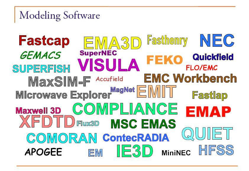
7 Tool Bo Approach There is NO ONE modeling technique that will do everything Vendor claims must be carefully eamined For Real-World applications EMC engineers need Tools at various modeling levels A variety of modeling techniques Bruce Archambeault, PhD 7
8 Range of Modeling Tools Quasi-Static Tools L,C,R Etraction Quick calculators Loop current emissions from PCB traces into near field locations Full Wave techniques Magic Bruce Archambeault, PhD 8
9 Quasi-Static Models Electrically small elements Typically 1/20 th of wavelength Lumped circuit approimation Commonly used for parameter etraction (RLC) in signal integrity tools Solve less comple equations for the problem geometry Assumes no propagation delay! Bruce Archambeault, PhD 9
10 Quasi-Static Advantages Simplified equations result in more efficient computer codes. Solutions are specific to the task at hand and do not generate etra unnecessary data. Often written to complement a circuit modeling tool such as SPICE. Bruce Archambeault, PhD 10
11 Quasi-Static Disadvantages It is important to ensure that the problem meets the criteria for the quasi-static static solution to be valid. All dimensions must be electrically small. No Propagation delay!!! This is becoming very difficult with the ever increasing frequencies of concern Eample: 3cm backplane high speed connector QS accurate to about < 5 GHz! Bruce Archambeault, PhD 11


12 Quasi Static Eamples Bruce Archambeault, PhD 12
13 Full Wave Modeling Techniques Finite-Difference Time-Domain (FDTD) Method of Moments (MoM) Partial Element Equivalent Circuit (PEEC) Transmission Line Method (TLM) Finite Element Method Others Bruce Archambeault, PhD 13
14 Popular Modeling Techniques Don t t need Ph.D. to use them Codes are available in many forms Free from Universities User beware Purchase from vendors User beware User should understand basic techniques and their limitations Bruce Archambeault, PhD 14
15 Popular Modeling Techniques Each technique has areas where it ecels and areas where limitations apply Different modeling tasks require different techniques Bruce Archambeault, PhD 15
16 Mathematical Foundation Electromagnetic Simulation Analytic formulas Integral equation methods (Integral calculus) MoM PEEC Differential equation methods (differential calculus) FEM FDTD TLM... Bruce Archambeault, PhD 16
17 Read CAD File Directly? Too much information! Models too large for practical solution Need human to decide what is important Models take days to run Models may require BlueGene computer! Human can usually decide what is most important and simplify problem to a reasonable size BEWARE of models with too much detail! Bruce Archambeault, PhD 17

18 Number of Unknowns Huge! Bruce Archambeault, PhD 18
19 Finite-Difference Time-Domain Technique (FDTD)
20 Introduction to FDTD All of space must be divided into electrically small grids Fields are assumed to be constant over cell Each grid location assigned as Air, Metal, Dielectric, etc. Usually cube or rectangular grids Time Domain Technique Wide band of frequencies analyzed at once FFT to get frequency domain information Bruce Archambeault, PhD 20
21 Mawell s s Equations Differential Form A difference in Magnetic Field across a small piece of space A difference in Electric Field across a small piece of space H E = J = + B t D t A change in Electric Flu Density with respect to time A change in Magnetic Flu Density with respect to time Bruce Archambeault, PhD 21
22 Changing to Difference Equations E = B t E n i E n i 1 µ = ( ) H n i + 1 H n i t Bruce Archambeault, PhD 22
23 Bruce Archambeault, PhD Bruce Archambeault, PhD One One-Dimensional FDTD Dimensional FDTD Equations Equations [ ] [ ] n i n i n i n i n i n i n i n i H H t E t E E E t H H ) 1 ( = = ε ε σ µ
24 FDTD Fields at Each Time Step Electric field found from: Old electric field at that point Difference in magnetic field around that point Magnetic field found from: Old magnetic field at that point Difference in electric field around that point Bruce Archambeault, PhD 24
25 One-Dimensional FDTD Grid E H E H E H E H E H E H E Bruce Archambeault, PhD 25
26 FDTD Time Marching Initial Time E H E H E H E H E H E H E Initial Time + 1 E H E H E H E H E H E H E Initial Time + 2 E H E H E H E H E H E H E Bruce Archambeault, PhD 26
27 Two-Dimensional FDTD Grid E-Field H-Field Bruce Archambeault, PhD 27
28 Two-Dimensional FDTD Can use TE or TM Case Only three fields available 2 Electric Fields and 1 Magnetic Field 1 Electric Field and 2 Magnetic Fields Assume all structures are infinite in 3rd dimension Bruce Archambeault, PhD 28
29 Three Dimensional FDTD Grid Ez Hy H Ey E Hz Bruce Archambeault, PhD 29
30 FDTD Cells Hy Ez Ey Cell 1,1,2 Cell 1,2,2 Hy Ez H H Ey E Hz E Hz Hy Cell 1,1,1 Ez H Ey Hy Ez Ey Cell 1,2,1 H E Hz E Hz Bruce Archambeault, PhD 30
31 FDTD 3-D3 Cell 1,1,2 Cell 1,2,2 Hy Hz E Hz Cell 1,1,1 Hy Cell 1,2,1 Bruce Archambeault, PhD 31
32 FDTD 3-D3 Cell 1,1,2 Cell 1,2,2 Ey E Hz E Cell 1,1,1 Cell 1,2,1 Bruce Archambeault, PhD 32
33 FDTD Materials Each Cell is Assigned as PEC, Metal, Dielectric, etc. Must Know --- σ µ ε Bruce Archambeault, PhD 33
34 FDTD Model Outputs Monitor Points Only fields directly Perfect receive antennas Both E and H fields X,Y,Z Components individually Animations Slice Through space Provide confidence and understanding Bruce Archambeault, PhD 34
35 FDTD Mesh Truncation FDTD Computational Domain Boundary Acts as if free-space continues to infinity E-Field H-Field Bruce Archambeault, PhD 35
36 FDTD Mesh Truncation Types Must match the impedance of the fields at the boundary point. Most require far field conditions, so impedance is well known Based upon the Wave Equation Liao Higdon Bruce Archambeault, PhD 36
37 Perfectly Matched Layer Loss is added to both E and H field Equations Acts similar to absorbing material in anechoic rooms Far fields required for lowest error (Reflection) Bruce Archambeault, PhD 37
38 Other Considerations Time Step Size Time step must be small enough so that fields do NOT propagate faster than the Speed of Light.. Courant s s stability condition t v y z 2 v = c µ ε r r Bruce Archambeault, PhD 38
39 Summary -- FDTD FDTD is a volume based technique Entire domain must be gridded Wide range of frequencies with one simulation Finds E and H Fields everywhere in domain Simple to learn and use Brute force approach Bruce Archambeault, PhD 39
40 FDTD Strengths and Weaknesses Strengths Very well suited to shielding problems, or problems with dielectrics, lossy materials, etc. Allows infinite planes to remove resonances Weaknesses Not well suited to problems with long wires Sensitive to resonances Bruce Archambeault, PhD 40
41 The Method of Moments
42 Method of Moments (MoM) Boundary Element Method (BEM) Break all surfaces into electrically small patches Break all wires into electrically small segments Assume RF current does not vary across a patch or segment Frequency domain technique Model must be run for each harmonic frequency of interest Bruce Archambeault, PhD 42
43 Method of Moments (MoM) RF Current on every patch and segment found Due to source and currents on all other patches and segments Electric/Magnetic fields found at any point by summing the contribution of all currents May include assumptions about far field locations Bruce Archambeault, PhD 43
44 MoM: Modeling Eamples Current on Eternal Wires IDENTIFY SEGMENTS, PATCHES & SOURCE LOCATION Bruce Archambeault, PhD 44
45 MoM: Modeling Eamples Current on Eternal Wires RF CURRENTS ARE FOUND ON EACH SEGMENT/PATCH DUE TO SOURCE & CURRENT ON EVERY OTHER SEGMENT/PATCH Bruce Archambeault, PhD 45
46 MoM: Modeling Eamples Current on Eternal Wires RF CURRENTS ARE FOUND ON EACH SEGMENT/PATCH DUE TO SOURCE & CURRENT ON EVERY OTHER SEGMENT/PATCH Bruce Archambeault, PhD 46
47 MoM: Basis Functions Sub-domain basis functions Pulse functions (piecewise constant) Linear Piecewise sinusoidal Bruce Archambeault, PhD 47
48 Impulse and Pulse Basis Functions level impulse pulse Position Note: Discontinuous current Bruce Archambeault, PhD 48
49 Triangle Basis Functions triangle1 triangle2 triangle3 triangle4 triangle sum 0.4 level position Note: Continuous current but discontinuous di/dt Bruce Archambeault, PhD 49
50 Sine Squared Basis Function sine1 sine2 sine3 sine4 sine sum 0.4 level position Note: Continuous current and continuous di/dt Bruce Archambeault, PhD 50
51 Basis Functions Simplest basis function requires one calculation per grid Requires more grids per wavelength to correctly estimate current/field/etc More comple basis function requires many calculations per grid Requires less grids per wavelength More comple calculations (longer calculation time) Bruce Archambeault, PhD 51
52 MoM: Summary MoM is a Surface based technique Frequency domain technique simulation must be repeated for each harmonic frequency Currents are found everywhere Fields found from currents Good for wire and surface structures Simple to learn and use Bruce Archambeault, PhD 52
53 MoM Strengths and Weaknesses Strengths Very well suited to problems with long wires Well suited to problems with large distances Weaknesses Not well suited to shielding problems Not well suited to problems with dielectrics or lossy materials Bruce Archambeault, PhD 53
54 The Finite Elements Method Bruce Archambeault, PhD 54
55 Finite Element Method (FEM) All space must be divided into electrically small elements Each grid location assigned as air, metal, dielectric, etc. Usually triangular or tetrahedral elements Fields found in each element using variational techniques Frequency domain technique Model must be run for each harmonic frequency of interest Bruce Archambeault, PhD 55
56 Why FEM? Ideal for problems with irregular geometry Can handle different material easily Results in sparse matrices which can be solved very efficiently with efficient storage Bruce Archambeault, PhD 56
57 FEM in English Entire volume is broken into small elements Energy in each element is due to the electric (or magnetic) field in that element Take 1 st derivative of sum of energy in all elements to find minimum energy overall Electric (or magnetic) fields are found from this final energy in each element Bruce Archambeault, PhD 57
58 FEM: Elements Construction Construction of Finite Elements triangular elements Bruce Archambeault, PhD 58
59 Bruce Archambeault, PhD Bruce Archambeault, PhD FEM: System Matri FEM: System Matri Sparse and banded
60 FEM: Any Advantage? Significant advantage over Method of Moments for equal number of unknowns (non-homogeneous,, non-metallic objects) Mesh generation is becoming easier and more powerful Mesh geometry can sometimes be shared with other non-em solvers (thermal/mechanical CAD tools) Bruce Archambeault, PhD 60
61 FEM: Summary FEM is a Volume Based Technique (Entire domain must be meshed) Frequency-domain FEM (classical FEM) A single simulation for one frequency Time-domain FEM (not widely available) One simulation for wide band frequency response. Calculates E or H everywhere in domain Bruce Archambeault, PhD 61
62 FEM Strengths and Weaknesses Strengths Well suited to bound problems Waveguides, Resonant Cavity, etc. Well suited to problems with large size differences within model Weaknesses Not well suited for problems with long wires or problems with open boundaries Absorbing Boundary Conditions may cause spurious response Bruce Archambeault, PhD 62
63 Model Validation GIGO Works!!!!
64 Validation Summary Three different levels of validation Most important to practicing engineer is specific model validation Intermediate results and different simulation technique are the best source of validation Use other approaches as desired BEWARE of measurement comparison NEVER TRUST a single model result! Bruce Archambeault, PhD 64
65 Validation Summary (2) It is not sufficient to simply believe the results are correct Previous model validation on different problems does not guarantee results from new models GIGO applies!!! Need to understand the physics of the problem Need to understand the limitations of the modeling technique and software tools Bruce Archambeault, PhD 65
66 Where to go for More Information Web sites Books EMI/EMC Computational Modeling Handbook Conferences Seminars Validation IEEE Std 1597 Bruce Archambeault, PhD 66
67 Computational Electromagnetics Web Sites Bruce Archambeault, PhD 67
68 Modeling Information Unofficial NEC Page Mesh Generation users.informatik.rwth-aachen aachen.de/~roberts/meshgeneration.html FDTD Information Html FEM Books Modeling techniques Books on Modeling Bruce Archambeault, PhD 68
69 Where To Go For More IBM offers EMC Tools, training, and consulting University of Missouri-Rolla Most complete graduate program on EMC Bruce Archambeault, PhD 69


70 Bruce Archambeault, PhD 70


71 Bruce Archambeault, PhD 71
The analysis of microstrip antennas using the FDTD method
 Computational Methods and Experimental Measurements XII 611 The analysis of microstrip antennas using the FDTD method M. Wnuk, G. Różański & M. Bugaj Faculty of Electronics, Military University of Technology,
Computational Magic and the EMC Engineer
 Computational Magic and the EMC Engineer By Glen Dash, Ampyx LLC, GlenDash at alum.mit.edu Copyright 1999, 2005 Ampyx LLC Using a computer to simulate EMC phenomena is a field full of promise. In decades
EMDS for ADS Momentum
 EMDS for ADS Momentum ADS User Group Meeting 2009, Böblingen, Germany Prof. Dr.-Ing. Frank Gustrau Gustrau, Dortmund User Group Meeting 2009-1 Univ. of Applied Sciences and Arts (FH Dortmund) Presentation
Comparative Analysis of Intel Pentium 4 and IEEE/EMC TC-9/ACEM CPU Heat Sinks
 Comparative Analysis of Intel Pentium 4 and IEEE/EMC TC-9/ACEM CPU Heat Sinks Author Lu, Junwei, Duan, Xiao Published 2007 Conference Title 2007 IEEE International Symposium on Electromagnetic Compatibility
Chapter 1 - Antennas
 EE 483/583/L Antennas for Wireless Communications 1 / 8 1.1 Introduction Chapter 1 - Antennas Definition - That part of a transmitting or receiving system that is designed to radiate or to receive electromagnetic
Comparison of Various Numerical Modeling Tools Against a Standard Problem Concerning Heat Sink Emissions
 Comparison of Various Numerical Modeling Tools Against a Standard Problem Concerning Heat Sink Emissions Bruce Archambeault, Ph.D. Satish Pratapneni David C. Wittwer, Ph.D. Lauren Zhang IBM Dell Intel
Waveguides. Metal Waveguides. Dielectric Waveguides
 Waveguides Waveguides, like transmission lines, are structures used to guide electromagnetic waves from point to point. However, the fundamental characteristics of waveguide and transmission line waves
Modeling and Simulation of Powertrains for Electric and Hybrid Vehicles
 Modeling and Simulation of Powertrains for Electric and Hybrid Vehicles Dr. Marco KLINGLER PSA Peugeot Citroën Vélizy-Villacoublay, FRANCE marco.klingler@mpsa.com FR-AM-5 Background The automotive context
THE PROBLEM of electromagnetic interference between
 IEEE TRANSACTIONS ON ELECTROMAGNETIC COMPATIBILITY, VOL. 50, NO. 2, MAY 2008 399 Estimation of Current Distribution on Multilayer Printed Circuit Board by Near-Field Measurement Qiang Chen, Member, IEEE,
Projects in microwave theory 2017
 Electrical and information technology Projects in microwave theory 2017 Write a short report on the project that includes a short abstract, an introduction, a theory section, a section on the results and
Analysis of Crack Detection in Metallic and Non-metallic Surfaces Using FDTD Method
 ECNDT 26 - We.4.3.2 Analysis of Crack Detection in Metallic and Non-metallic Surfaces Using FDTD Method Faezeh Sh.A.GHASEMI 1,2, M. S. ABRISHAMIAN 1, A. MOVAFEGHI 2 1 K. N. Toosi University of Technology,
Predicting and Controlling Common Mode Noise from High Speed Differential Signals
 Predicting and Controlling Common Mode Noise from High Speed Differential Signals Bruce Archambeault, Ph.D. IEEE Fellow, inarte Certified Master EMC Design Engineer, Missouri University of Science & Technology
EMC cases study. Antonio Ciccomancini Scogna, CST of America CST COMPUTER SIMULATION TECHNOLOGY
 EMC cases study Antonio Ciccomancini Scogna, CST of America antonio.ciccomancini@cst.com Introduction Legal Compliance with EMC Standards without compliance products can not be released to the market Failure
Antennas and Propagation. Chapter 4: Antenna Types
 Antennas and Propagation : Antenna Types 4.4 Aperture Antennas High microwave frequencies Thin wires and dielectrics cause loss Coaxial lines: may have 10dB per meter Waveguides often used instead Aperture
SAR REDUCTION IN SLOTTED PIFA FOR MOBILE HANDSETS USING RF SHIELD
 SAR REDUCTION IN SLOTTED PIFA FOR MOBILE HANDSETS USING RF SHIELD T. Anita Jones Mary 1 and C. S. Ravichandran 2 1 Department of Electronics and Communication, Karunya University, Coimbatore, India 2 SSK
The Ground Myth IEEE. Bruce Archambeault, Ph.D. IBM Distinguished Engineer, IEEE Fellow 18 November 2008
 The Ground Myth Bruce Archambeault, Ph.D. IBM Distinguished Engineer, IEEE Fellow barch@us.ibm.com 18 November 2008 IEEE Introduction Electromagnetics can be scary Universities LOVE messy math EM is not
Analysis of Microstrip Circuits Using a Finite-Difference Time-Domain Method
 Analysis of Microstrip Circuits Using a Finite-Difference Time-Domain Method M.G. BANCIU and R. RAMER School of Electrical Engineering and Telecommunications University of New South Wales Sydney 5 NSW
EM Noise Mitigation in Electronic Circuit Boards and Enclosures
 EM Noise Mitigation in Electronic Circuit Boards and Enclosures Omar M. Ramahi, Lin Li, Xin Wu, Vijaya Chebolu, Vinay Subramanian, Telesphor Kamgaing, Tom Antonsen, Ed Ott, and Steve Anlage A. James Clark
Electromagnetic Wave Analysis of Waveguide and Shielded Microstripline 1 Srishti Singh 2 Anupma Marwaha
 Electromagnetic Wave Analysis of Waveguide and Shielded Microstripline 1 Srishti Singh 2 Anupma Marwaha M.Tech Research Scholar 1, Associate Professor 2 ECE Deptt. SLIET Longowal, Punjab-148106, India
An Efficient Hybrid Method for Calculating the EMC Coupling to a. Device on a Printed Circuit Board inside a Cavity. by a Wire Penetrating an Aperture
 An Efficient Hybrid Method for Calculating the EMC Coupling to a Device on a Printed Circuit Board inside a Cavity by a Wire Penetrating an Aperture Chatrpol Lertsirimit David R. Jackson Donald R. Wilton
ADVANCED MODELING IN COMPUTATIONAL ELECTROMAGNETIC COMPATIBILITY
 ADVANCED MODELING IN COMPUTATIONAL ELECTROMAGNETIC COMPATIBILITY DRAGAN POLJAK, PhD Department of Electronics University of Split, Croatia BICENTENNIAL 1 8 O 7 WILEY 2 O O 7 ICENTENNIAL WILEY-INTERSCIENCE
Combining Differential/Integral Methods and Time/Frequency Domain Analysis to Solve Complex Antenna Problems
 Combining Differential/Integral Methods and Time/Frequency Domain Analysis to Solve Complex Antenna Problems IEEE Long Island Section MTT-S Jan. 27, 20 Overview of Presentation Antenna design challenges
The Evolution of Waveform Relaxation for Circuit and Electromagnetic Solvers
 The Evolution of Waveform Relaxation for Circuit and Electromagnetic Solvers Albert Ruehli, Missouri S&T EMC Laboratory, University of Science & Technology, Rolla, MO with contributions by Giulio Antonini,
Projects in microwave theory 2009
 Electrical and information technology Projects in microwave theory 2009 Write a short report on the project that includes a short abstract, an introduction, a theory section, a section on the results and
Microwave and optical systems Introduction p. 1 Characteristics of waves p. 1 The electromagnetic spectrum p. 3 History and uses of microwaves and
 Microwave and optical systems Introduction p. 1 Characteristics of waves p. 1 The electromagnetic spectrum p. 3 History and uses of microwaves and optics p. 4 Communication systems p. 6 Radar systems p.
FEM simulations of nanocavities for plasmon lasers
 FEM simulations of nanocavities for plasmon lasers S.Burger, L.Zschiedrich, J.Pomplun, F.Schmidt Zuse Institute Berlin JCMwave GmbH 6th Workshop on Numerical Methods for Optical Nano Structures ETH Zürich,
Antenna Design: Simulation and Methods
 Antenna Design: Simulation and Methods Radiation Group Signals, Systems and Radiocommunications Department Universidad Politécnica de Madrid Álvaro Noval Sánchez de Toca e-mail: anoval@gr.ssr.upm.es Javier
Methods and Approaches for RF Circuit Simulation And Electromagnetic Modelling
 Methods and Approaches for RF Circuit Simulation And Electromagnetic Modelling T.A.M. Kevenaar 1, E.J.W. ter Maten 1, H.H.J. Janssen 1, S. Onneweer 2 1 Philips Research, Eindhoven, The Netherlands 2 Philips
RF simulations with COMSOL
 RF simulations with COMSOL ICPS 217 Politecnico di Torino Aug. 1 th, 217 Gabriele Rosati gabriele.rosati@comsol.com 3 37.93.8 Copyright 217 COMSOL. Any of the images, text, and equations here may be copied
Phased Array Simulations using Finite Integration Technique
 Phased Array Simulations using Finite Integration Technique Franz Hirtenfelder CST GmbH, Bad Nauheimerstr. 19, 64289 Darmstadt, Germany Phone : +49 6151 73030, Fa : +49 6151 730310 Web: http://www.cst.com
Introduction to Electromagnetic Compatibility
 Introduction to Electromagnetic Compatibility Second Edition CLAYTON R. PAUL Department of Electrical and Computer Engineering, School of Engineering, Mercer University, Macon, Georgia and Emeritus Professor
Correlation Between Measured and Simulated Parameters of a Proposed Transfer Standard
 Correlation Between Measured and Simulated Parameters of a Proposed Transfer Standard Jim Nadolny AMP Incorporated ABSTRACT Total radiated power of a device can be measured using a mode stirred chamber
Rectangular waveguides
 Introduction Rectangular waveguides Waveguides are transmission lines commonly used in electronics, especially in higher frequency ranges like microwaves. A waveguide can be simply described as a metal
Full Wave Solution for Intel CPU With a Heat Sink for EMC Investigations
 Full Wave Solution for Intel CPU With a Heat Sink for EMC Investigations Author Lu, Junwei, Zhu, Boyuan, Thiel, David Published 2010 Journal Title I E E E Transactions on Magnetics DOI https://doi.org/10.1109/tmag.2010.2044483
Examining The Concept Of Ground In Electromagnetic (EM) Simulation
 Simulation") Examining The Concept Of Ground In Electromagnetic (EM) Simulation While circuit simulators require a global ground, EM simulators don t concern themselves with ground at all. As a result, it is the designer
Examining The Concept Of Ground In Electromagnetic (EM) Simulation While circuit simulators require a global ground, EM simulators don t concern themselves with ground at all. As a result, it is the designer
Advanced Meshing Techniques
 Advanced Meshing Techniques Ansoft High Frequency Structure Simulator v10 Training Seminar P-1 Overview Initial Mesh True Surface Approximation Surface Approximation Operations Lambda Refinement Seeding
ECSE 352: Electromagnetic Waves
 December 2008 Final Examination ECSE 352: Electromagnetic Waves 09:00 12:00, December 15, 2008 Examiner: Zetian Mi Associate Examiner: Andrew Kirk Student Name: McGill ID: Instructions: This is a CLOSED
Critical Study of Open-ended Coaxial Sensor by Finite Element Method (FEM)
") International Journal of Applied Science and Engineering 3., 4: 343-36 Critical Study of Open-ended Coaxial Sensor by Finite Element Method (FEM) M. A. Jusoha*, Z. Abbasb, M. A. A. Rahmanb, C. E. Mengc,
International Journal of Applied Science and Engineering 3., 4: 343-36 Critical Study of Open-ended Coaxial Sensor by Finite Element Method (FEM) M. A. Jusoha*, Z. Abbasb, M. A. A. Rahmanb, C. E. Mengc,
UNIT - V WAVEGUIDES. Part A (2 marks)
") Part A (2 marks) UNIT - V WAVEGUIDES 1. What is the need for guide termination? (Nov / Dec 2011) To avoid reflection loss. The termination should provide a wave impedance equal to that of the transmission
Part A (2 marks) UNIT - V WAVEGUIDES 1. What is the need for guide termination? (Nov / Dec 2011) To avoid reflection loss. The termination should provide a wave impedance equal to that of the transmission
An Efficient and Accurate Method to Solve Low Frequency and Non-Conformal Problems Using Finite Difference Time Domain (FDTD)
") Progress In Electromagnetics Research, Vol. 50, 83 96, 205 An Efficient and Accurate Method to Solve Low Frequency and Non-Conformal Problems Using Finite Difference Time Domain (FDTD) Kadappan Panayappan
Progress In Electromagnetics Research, Vol. 50, 83 96, 205 An Efficient and Accurate Method to Solve Low Frequency and Non-Conformal Problems Using Finite Difference Time Domain (FDTD) Kadappan Panayappan
Study of Microstrip Slotted Antenna for Bandwidth Enhancement
 Global Journal of Researches in Engineering Electrical and Electronics Engineering Volume 2 Issue 9 Version. Type: Double Blind Peer Reviewed International Research Journal Publisher: Global Journals Inc.
Design Fundamentals by A. Ciccomancini Scogna, PhD Suppression of Simultaneous Switching Noise in Power and Ground Plane Pairs
 Design Fundamentals by A. Ciccomancini Scogna, PhD Suppression of Simultaneous Switching Noise in Power and Ground Plane Pairs Photographer: Janpietruszka Agency: Dreamstime.com 36 Conformity JUNE 2007
The Impedance Variation with Feed Position of a Microstrip Line-Fed Patch Antenna
 SERBIAN JOURNAL OF ELECTRICAL ENGINEERING Vol. 11, No. 1, February 2014, 85-96 UDC: 621.396.677.5:621.3.011.21 DOI: 10.2298/SJEE131121008S The Impedance Variation with Feed Position of a Microstrip Line-Fed
INVESTIGATION OF THE LONGITUDINAL FIELD COMPONENT INSIDE THE GTEM 1750
 INVESTIGATION OF THE LONGITUDINAL FIELD COMPONENT INSIDE THE GTEM 1750 H.M. LOOE, Y. HUANG B.G. LOADER, M.J. ALEXANDER, W. LIANG The University of Liverpool, UK Introduction GTEM (Gigahertz Traverse Electromagnetic)
Photograph of the rectangular waveguide components
 Waveguides Photograph of the rectangular waveguide components BACKGROUND A transmission line can be used to guide EM energy from one point (generator) to another (load). A transmission line can support
E. Nishiyama and M. Aikawa Department of Electrical and Electronic Engineering, Saga University 1, Honjo-machi, Saga-shi, , Japan
 Progress In Electromagnetics Research, PIER 33, 9 43, 001 FDTD ANALYSIS OF STACKED MICROSTRIP ANTENNA WITH HIGH GAIN E. Nishiyama and M. Aikawa Department of Electrical and Electronic Engineering, Saga
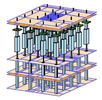
Decomposition of Coplanar and Multilayer Interconnect Structures with Split Power Distribution Planes for Hybrid Circuit Field Analysis
 DesignCon 23 High-Performance System Design Conference Decomposition of Coplanar and Multilayer Interconnect Structures with Split Power Distribution Planes for Hybrid Circuit Field Analysis Neven Orhanovic
Lecture 8: Introduction to Hybrid FEM IE
 Lecture 8: Introduction to Hybrid FEM IE 2015.0 Release ANSYS HFSS for Antenna Design 1 2015 ANSYS, Inc. Hybrid FEM-IE Solution Using HFSS and HFSS-IE Advantages of Hybrid Solution Leverage the strength
Description of TEAM Workshop Problem 29: Whole body cavity resonator
 Description of TEAM Workshop Problem 29: Whole body cavity resonator Yasushi Kanai Department of Information and Electronics Engineering, Niigata Institute of Technology, Kashiwazaki 945-1195, JAPAN Tel:
Pre-construction Evaluation Modeling of Open Area Test Sites (OATS)
") Preconstruction Evaluation Modeling of Open Area Test Sites (OATS) Bruce Archambeault IBM Raleigh, N.C. Introduction The construction of Open Area Test Sites (OATS) for commercial EM1 testing for FCC and
Preconstruction Evaluation Modeling of Open Area Test Sites (OATS) Bruce Archambeault IBM Raleigh, N.C. Introduction The construction of Open Area Test Sites (OATS) for commercial EM1 testing for FCC and
ELECTROMAGNETIC COMPATIBILITY HANDBOOK 1. Chapter 8: Cable Modeling
 ELECTROMAGNETIC COMPATIBILITY HANDBOOK 1 Chapter 8: Cable Modeling Related to the topic in section 8.14, sometimes when an RF transmitter is connected to an unbalanced antenna fed against earth ground
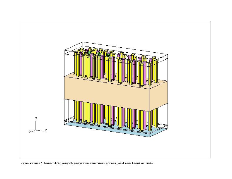
Application of Foldy-Lax Multiple Scattering Method To Via Analysis in Multi-layered Printed Circuit Board
 DesignCon 2008 Application of Foldy-Lax Multiple Scattering Method To Via Analysis in Multi-layered Printed Circuit Board Xiaoxiong Gu, IBM T. J. Watson Research Center xgu@us.ibm.com Mark B. Ritter, IBM
Electromagnetics, Microwave Circuit and Antenna Design for Communications Engineering
 Electromagnetics, Microwave Circuit and Antenna Design for Communications Engineering Second Edition Peter Russer ARTECH HOUSE BOSTON LONDON artechhouse.com Contents Preface xvii Chapter 1 Introduction
DEPARTMENT FOR CONTINUING EDUCATION
 DEPARTMENT FOR CONTINUING EDUCATION Reduce EMI Emissions for FREE! by Bruce Archambeault, Ph.D. (reprinted with permission from Bruce Archambeault) Bruce Archambeault presents two courses during the University
Department of Electrical Engineering University of North Texas
 Name: Shabuktagin Photon Khan UNT ID: 10900555 Instructor s Name: Professor Hualiang Zhang Course Name: Antenna Theory and Design Course ID: EENG 5420 Email: khan.photon@gmail.com Department of Electrical
EMC problems from Common Mode Noise on High Speed Differential Signals
 EMC problems from Common Mode Noise on High Speed Differential Signals Bruce Archambeault, PhD Alma Jaze, Sam Connor, Jay Diepenbrock IBM barch@us.ibm.com 1 Differential Signals Commonly used for high
High Frequency Structure Simulator (HFSS) Tutorial
 Tutorial") High Frequency Structure Simulator (HFSS) Tutorial Prepared by Dr. Otman El Mrabet IETR, UMR CNRS 6164, INSA, 20 avenue Butte des Coësmes 35043 Rennes, FRANCE 2005-2006 TABLE OF CONTENTS INTRODUCTION...
High Frequency Structure Simulator (HFSS) Tutorial Prepared by Dr. Otman El Mrabet IETR, UMR CNRS 6164, INSA, 20 avenue Butte des Coësmes 35043 Rennes, FRANCE 2005-2006 TABLE OF CONTENTS INTRODUCTION...
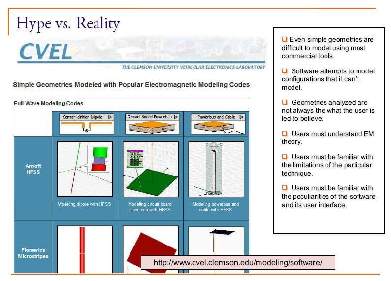
Todd H. Hubing Michelin Professor of Vehicular Electronics Clemson University
 Essential New Tools for EMC Diagnostics and Testing Todd H. Hubing Michelin Professor of Vehicular Electronics Clemson University Where is Clemson University? Clemson, South Carolina, USA Santa Clara Valley
Absorbers and Anechoic Chamber Measurements
 Absorbers and Anechoic Chamber Measurements Zhong Chen Director, RF Engineering ETS-Lindgren 1301 Arrow Point Dr. Cedar Park, TX, 78613 Zhong.chen@ets-lindgren.com SUMMARY Absorber Overview Absorber Materials
Using Sonnet EM Analysis with Cadence Virtuoso in RFIC Design. Sonnet Application Note: SAN-201B July 2011
 Using Sonnet EM Analysis with Cadence Virtuoso in RFIC Design Sonnet Application Note: SAN-201B July 2011 Description of Sonnet Suites Professional Sonnet Suites Professional is an industry leading full-wave
ANTENNAS FROM THEORY TO PRACTICE WILEY. Yi Huang University of Liverpool, UK. Kevin Boyle NXP Semiconductors, UK
 ANTENNAS FROM THEORY TO PRACTICE Yi Huang University of Liverpool, UK Kevin Boyle NXP Semiconductors, UK WILEY A John Wiley and Sons, Ltd, Publication Contents Preface Acronyms and Constants xi xiii 1
EC Transmission Lines And Waveguides
 EC6503 - Transmission Lines And Waveguides UNIT I - TRANSMISSION LINE THEORY A line of cascaded T sections & Transmission lines - General Solution, Physical Significance of the Equations 1. Define Characteristic
FEKO-Based Method for Electromagnetic Simulation of Carcass Wires Embedded in Vehicle Tires
 ACES JOURNAL, VOL. 26, NO. 3, MARCH 2011 217 FEKO-Based Method for Electromagnetic Simulation of Carcass Wires Embedded in Vehicle Tires Nguyen Quoc Dinh 1, Takashi Teranishi 1, Naobumi Michishita 1, Yoshihide
Progress In Electromagnetics Research, PIER 36, , 2002
 Progress In Electromagnetics Research, PIER 36, 247 264, 2002 ELECTROMAGNETIC COUPLING ANALYSIS OF TRANSIENT SIGNAL THROUGH SLOTS OR APERTURES PERFORATED IN A SHIELDING METALLIC ENCLOSURE USING FDTD METHODOLOGY
FDTD CHARACTERIZATION OF MEANDER LINE ANTENNAS FOR RF AND WIRELESS COMMUNICATIONS
 Progress In Electromagnetics Research, PIER 4, 85 99, 999 FDTD CHARACTERIZATION OF MEANDER LINE ANTENNAS FOR RF AND WIRELESS COMMUNICATIONS C.-W. P. Huang, A. Z. Elsherbeni, J. J. Chen, and C. E. Smith
EC TRANSMISSION LINES AND WAVEGUIDES TRANSMISSION LINES AND WAVEGUIDES
 TRANSMISSION LINES AND WAVEGUIDES UNIT I - TRANSMISSION LINE THEORY 1. Define Characteristic Impedance [M/J 2006, N/D 2006] Characteristic impedance is defined as the impedance of a transmission line measured
A VIEW OF ELECTROMAGNETIC LIFE ABOVE 100 MHz
 A VIEW OF ELECTROMAGNETIC LIFE ABOVE 100 MHz An Experimentalist's Intuitive Approach Lothar O. (Bud) Hoeft, PhD Consultant, Electromagnetic Effects 5012 San Pedro Ct., NE Albuquerque, NM 87109-2515 (505)
Electromagnetic Analysis of Decoupling Capacitor Mounting Structures with Simbeor
 Simbeor Application Note #2008_01, March 2008 2008 Simberian Inc. Electromagnetic Analysis of Decoupling Capacitor Mounting Structures with Simbeor Simberian, Inc. www.simberian.com Simbeor: Easy-to-Use,
A FDTD Program for Computing Responses on Branched Multi-conductor Transmission Lines
 A FDTD Program for Computing Responses on Branched Multi-conductor Transmission Lines Jan Carlsson 998:6 Abstract This document gives a description of a finite difference time domain (FDTD) program that
Frequency Response Calculations of Input Characteristics of Cavity-Backed Aperture Antennas Using AWE With Hybrid FEM/MoM Technique
 NASA Contractor Report 4764 Frequency Response Calculations of Input Characteristics of Cavity-Backed Aperture Antennas Using AWE With Hybrid FEM/MoM Technique C. J. Reddy Hampton University Hampton, Virginia
Introduction: Planar Transmission Lines
 Chapter-1 Introduction: Planar Transmission Lines 1.1 Overview Microwave integrated circuit (MIC) techniques represent an extension of integrated circuit technology to microwave frequencies. Since four
Numerical Calibration of Standard Gain Horns and OEWG Probes
 Numerical Calibration of Standard Gain Horns and OEWG Probes Donald G. Bodnar dbodnar@mi-technologies.com MI Technologies 1125 Satellite Blvd, Suite 100 Suwanee, GA 30024 ABSTRACT The gain-transfer technique
ABSTRACT. Baharak Mohajeriravani Master of Science, Electromagnetic Interference (EMI) in electronic devices is one of the major
 in electronic devices is one of the major") ABSTRACT Title of Thesis: COUPLING REDUCTION USING ELECTROMAGNETIC BAND GAP STRUCTURES IN ENCLOSURES AND CAVITIES Baharak Mohajeriravani Master of Science, 2004 Thesis Directed By: Dr. Omar M. Ramahi,
ABSTRACT Title of Thesis: COUPLING REDUCTION USING ELECTROMAGNETIC BAND GAP STRUCTURES IN ENCLOSURES AND CAVITIES Baharak Mohajeriravani Master of Science, 2004 Thesis Directed By: Dr. Omar M. Ramahi,
Resonant EBG-Based Common Mode Filter for LTCC Substrates
 UAq EMC Laboratory Resonant EBG-Based Common Mode Filter for LTCC Substrates C. Olivieri, F. De Paulis, A. Orlandi S. Connor, B.Archambeault UAq EMC Laboratory, University of L'Aquila, L'Aquila, Italy
Relationship Between Signal Integrity and EMC
 Relationship Between Signal Integrity and EMC Presented by Hasnain Syed Solectron USA, Inc. RTP, North Carolina Email: HasnainSyed@solectron.com 06/05/2007 Hasnain Syed 1 What is Signal Integrity (SI)?
Large E Field Generators in Semi-anechoic Chambers for Full Vehicle Immunity Testing
 Large E Field Generators in Semi-anechoic Chambers for Full Vehicle Immunity Testing Vince Rodriguez ETS-Lindgren, Inc. Abstract Several standards recommend the use of transmission line systems (TLS) as
Numerical and Experimental Analysis of Electromagnetic Field in a Probe Coupled Cylindrical Metallic Cavity
 Numerical and Experimental Analysis of Electromagnetic Field in a Probe Coupled Cylindrical Metallic Cavity JUGOSLAV JOKOVIC, BRATISLAV MILOVANOVIC, NEBOJSA DONCOV Department of Telecommunication University
Fundamentals of RF Design RF Back to Basics 2015
 Fundamentals of RF Design 2015 Updated January 1, 2015 Keysight EEsof EDA Objectives Review Simulation Types Understand fundamentals on S-Parameter Simulation Additional Linear and Non-Linear Simulators
A Complete Simulation of a Radiated Emission Test according to IEC
 34 PIERS Proceedings, August 27-30, Prague, Czech Republic, 2007 A Complete Simulation of a Radiated Emission Test according to IEC 61000-4-20 X. T. I Ngu, A. Nothofer, D. W. P. Thomas, and C. Christopoulos
Electromagnetic Analysis of Propagation and Scattering Fields in Dielectric Elliptic Cylinder on Planar Ground
 PIERS ONLINE, VOL. 5, NO. 7, 2009 684 Electromagnetic Analysis of Propagation and Scattering Fields in Dielectric Elliptic Cylinder on Planar Ground Yasumitsu Miyazaki 1, Tadahiro Hashimoto 2, and Koichi
Virtual EM Prototyping: From Microwaves to Optics
 Virtual EM Prototyping: From Microwaves to Optics Dr. Frank Demming, CST AG Dr. Avri Frenkel, Anafa Electromagnetic Solutions Virtual EM Prototyping Efficient Maxwell Equations solvers has been developed,
Transactions on Engineering Sciences vol 3, 1993 WIT Press, ISSN
 Simulation of electromagnetic pulse propagation in three-dimensionalfinite-differencetime-domain (FDTD) method using parallel processing techniques W.J. Buchanan, N.K. Gupta Department of Electrical, Electronic
IEEE TRANSACTIONS ON MICROWAVE THEORY AND TECHNIQUES, VOL. 58, NO. 5, MAY
 IEEE TRANSACTIONS ON MICROWAVE THEORY AND TECHNIQUES, VOL. 58, NO. 5, MAY 2010 1189 Using the LU Recombination Method to Extend the Application of Circuit-Oriented Finite Element Methods to Arbitrarily
 VALLIAMMAI ENGINEERING COLLEGE SRM Nagar, Kattankulathur-603 203 DEPARTMENT OF ELECTRONICS AND COMMUNICATION ENGINEERING EC6503 TRANSMISSION LINES AND WAVEGUIDES YEAR / SEMESTER: III / V ACADEMIC YEAR:
DETERMINATION OF GLACIAL-ICE TEMPERATURE PROFILES USING RADAR AND AN ANTENNA-GAIN ESTIMATION TECHNIQUE
 DETERMINATION OF GLACIAL-ICE TEMPERATURE PROFILES USING RADAR AND AN ANTENNA-GAIN ESTIMATION TECHNIQUE BY Mike Hughes Submitted to the graduate degree program in Electrical Engineering and the Graduate
Analysis of Waveguide Junction Discontinuities Using Finite Element Method
 NASA Contractor Report 201710 Analysis of Waveguide Junction Discontinuities Using Finite Element Method Manohar D. Deshpande ViGYAN, Inc., Hampton, Virginia Contract NAS1-19341 July 1997 National Aeronautics
7. Experiment K: Wave Propagation
 7. Experiment K: Wave Propagation This laboratory will be based upon observing standing waves in three different ways, through coaxial cables, in free space and in a waveguide. You will also observe some
DesignCon Control of Electromagnetic Radiation from Integrated Circuit Heat sinks. Cristian Tudor, Fidus Systems Inc.
 DesignCon 2009 Control of Electromagnetic Radiation from Integrated Circuit Heat sinks Cristian Tudor, Fidus Systems Inc. Cristian.Tudor@fidus.ca Syed. A. Bokhari, Fidus Systems Inc. Syed.Bokhari@fidus.ca
Triangular Patch Antennas for Mobile Radio-Communications Systems
 Triangular Patch Antennas for Mobile Radio-Communications Systems HECTOR FRAGA-ROSALES, MARIO REYES-AYALA, GENARO HERNANDEZ-VALDEZ, EDGAR ALEJANDRO ANDRADE-GONZALEZ, JOSE RAUL MIRANDA-TELLO, FELIPE ALEJANDRO
A VARACTOR-TUNABLE HIGH IMPEDANCE SURFACE FOR ACTIVE METAMATERIAL ABSORBER
 Progress In Electromagnetics Research C, Vol. 43, 247 254, 2013 A VARACTOR-TUNABLE HIGH IMPEDANCE SURFACE FOR ACTIVE METAMATERIAL ABSORBER Bao-Qin Lin *, Shao-Hong Zhao, Qiu-Rong Zheng, Meng Zhu, Fan Li,
Heat Sink Design Flow for EMC
 DesignCon 2008 Heat Sink Design Flow for EMC Philippe Sochoux, Cisco Systems, Inc. psochoux@cisco.com Jinghan Yu, Cisco Systems, Inc. jinyu@cisco.com Alpesh U. Bhobe, Cisco Systems, Inc. abhobe@cisco.com
Multilayer VIA simulations using ADS Anurag Bhargava, Application Consultant, Agilent EEsof EDA, Agilent Technologies
 Multilayer VIA simulations using ADS Anurag Bhargava, Application Consultant, Agilent EEsof EDA, Agilent Technologies Many a time designers find themselves in pretty confusing start when it comes to simulating
When Should You Apply 3D Planar EM Simulation?
 When Should You Apply 3D Planar EM Simulation? Agilent EEsof EDA IMS 2010 MicroApps Andy Howard Agilent Technologies 1 3D planar EM is now much more of a design tool Solves bigger problems and runs faster
Appendix. RF Transient Simulator. Page 1
 Appendix RF Transient Simulator Page 1 RF Transient/Convolution Simulation This simulator can be used to solve problems associated with circuit simulation, when the signal and waveforms involved are modulated
Five Tips for Successful 3D Electromagnetic Simulation
 Application Example Five Tips for Successful 3D Electromagnetic Simulation Overview This application example documents the steps taken to help a customer resolve a complex EM simulation problem in Analyst
Ultra-Wideband Antenna Simulations. Stanley Wang Prof. Robert W. Brodersen January 8, 2002
 Ultra-Wideband Antenna Simulations Stanley Wang Prof. Robert W. Brodersen January 8, 2002 Outline Antenna Basics Traditional Antenna Design UWB Antenna Design Challenges Tool: Electromagnetic Simulator
EC6503 Transmission Lines and WaveguidesV Semester Question Bank
 UNIT I TRANSMISSION LINE THEORY A line of cascaded T sections & Transmission lines General Solution, Physicasignificance of the equations 1. Derive the two useful forms of equations for voltage and current
OPEN TEM CELLS FOR EMC PRE-COMPLIANCE TESTING
 1 Introduction Radiated emission tests are typically carried out in anechoic chambers, using antennas to pick up the radiated signals. Due to bandwidth limitations, several antennas are required to cover
Plastic straw: future of high-speed signaling
 Supplementary Information for Plastic straw: future of high-speed signaling Ha Il Song, Huxian Jin, and Hyeon-Min Bae * Korea Advanced Institute of Science and Technology (KAIST), Department of Electrical
Microwave Engineering
 Microwave Circuits 1 Microwave Engineering 1. Microwave: 300MHz ~ 300 GHz, 1 m ~ 1mm. a. Not only apply in this frequency range. The real issue is wavelength. Historically, as early as WWII, this is the