CONCRETE MANHOLES.
|
|
|
- Oscar Stanley
- 5 years ago
- Views:
Transcription
1 CONCRETE

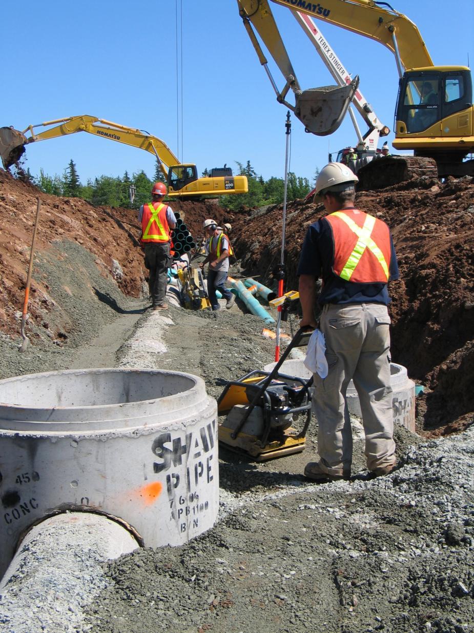
2 CONCRETE SHAW PIPE produces circular, precast, concrete manholes in diameters 1050mmØ through 3000mmØ. Precast, concrete manholes are most frequently used for pipeline and sewer entry and are easy to install and low in cost. SHAW PIPE follows various standards and specifications in the production of precast, concrete manhole units. These standards and specifications are listed in the "Specifications" section. Typical precast, concrete manhole configurations consist of a precast base or tee base, intermediate rings, flat top cover or eccentric cone top section, grade rings and cast iron frame and cover. Large diameter manholes or rectangular manholes can be precast upon request. S H A W P I P E P R O D U C T G U I D E A N D T E C H N I C A L R E F E R E N C E M A N U A L CONCRETE PIPE SECTION 3
3 GENERAL INFO How to Read SHAW PIPE Manhole Shop Drawings To manufacture a manhole for a specific project, certain information is required to develop shop drawings which are used by our production and shipping staff to manufacture and deliver the appropriate pieces which make up the manhole. Information which is necessary to develop a shop drawing normally comes from a set of engineering drawings containing a plan and profile of the sewer line. The minimum amount of information to determine required manhole layout: Finished Grade Elevation (or top of concrete cover if manhole extends above grade) Size and type of pipe entering the manhole (nominal diameter and pipe material) All pipe inverts (elevation at inside bottom of the pipe taken at the manhole wall) Angles between piping (measured clockwise from the outlet pipe which is taken as 0 ) Size of manhole (nominal inside diameter) Additional information which should be provided would include: Sump depth (if required) Base configuration (with or without benching, with or without bottom slab) Opening type (water tight rubber gasket, smooth or rough cut hole, doghouse opening.) Gasket type for joints / confined rubber o-ring, Ram-Nek butyl rubber strip, no gasket Special allowances for grade adjustment Type of access hatch or cover to be used (cast iron frame and cover, aluminum access hatch, etc.) Size and location of access opening in concrete cover Special items to be cast into manhole sections (lifting davits, access frames, tie downs) Once this information has been received, a standard shop drawing form is filled out for each manhole in the project. First, the total height of the manhole (laid height) is determined, by calculating the difference in elevation between the top of concrete cover and the lowest pipe invert (or bottom of sump). The top of concrete cover elevation is typically set as 300mm below finished grade, to provide an allowance for final grade adjustment once the manhole has been installed. Next, the pipe angles, size and type are determined and laid out. Angles and pipe inverts are checked to ensure sufficient clearance between adjacent pipes. All angles are measured clockwise from the outlet opening which is taken to be 0 degrees. For a manhole with two or more inlet pipes, the angle for each pipe relative to the outlet is determined. Next, the distance to the center of each pipe opening is determined ( + to CL). All distances are measured from the outside bottom of the manhole section in which the opening is located. Typically all openings are in the base section, unless there is a large change in elevation between pipes. If this is the case, the height of the base section, and intermediate sections will be adjusted to ensure that there is sufficient clearance between the opening and the manhole joints. Finally, the manhole sections are selected and listed, giving the laid height of each piece and any special requirements for each section. Opening types are listed for each pipe, and any special instructions are noted. Unless otherwise specified, shop drawings are sent to the contractor for review and approval by the project engineer. Any revisions required by the engineer or contractor are made, then the final approved shop drawings are issued to our production staff for fabrication. 1 CONCRETE SECTION 3 REF-24/25-12/06
4 Design Build Height Top of Casting m Outlet Invert m Design Height = 4.000m 1 Shaw Dr Highway #2 P.O. Box 2130 Lantz, NS B0N 1R0 Phone: (902) Fax: (902) Stack Build Height Structure: Job Number: Job Name: Job Location: Specification: Contractor: Based on: Frame m Adjustment m Eccentric Slab m Risers m Base Gain m Design Height = 4.000m Floor Thickness m Outside Height = 4.223m MANHOLE DRAWING JOB NAME JOB LOCATION 1050mm diameter CONTRACTOR NAME Produced By: Checked By: Frame/Ring: IMP R10 FRAME Grate/Cover: IMP R10 COVER Channel: 3-Way Half Height Bench Notes: Elevation (View A-A) Opening Schedule ID Center Pipe Size #1 376mm 300mm RCP B #2 426mm 300mm RCP B #3 426mm 300mm RCP B Plan View Hole Size 451mm 451mm 451mm Connector A-Lok535 A-Lok535 A-Lok535 Angle Dist. 0 0mm 90 1,017mm 180 2,034mm BOM For Stack Section ID Description Qty. Weight A G B AGC C AI ,269 D AI ,269 E APB 950 BN 1 1,757 Totals (pieces, kgs) 5 4,849 Submittal Page 1 of 1 Jan 5, 2006
5 GENERAL INFO MANHOLE DIAMETER SELECTION GUIDE 1050mm DIAMETER 525mmØ Alok # mmØ Alok # mmØ Alok # mmØ Alok # mmØ Alok # mmØ Alok # mm DIAMETER 600mmØ Alok # mmØ Alok # mmØ Alok # mmØ Alok # mmØ Alok # mmØ Alok #740 3 CONCRETE SECTION 3 REF-26-12/06
6 GENERAL INFO MANHOLE DIAMETER SELECTION GUIDE 1500mm DIAMETER 900mmØ Alok # mmØ Alok # mmØ Alok # mmØ Alok # mmØ Alok # mmØ Alok # mm DIAMETER 1050mmØ Alok # mmØ Alok # mmØ Alok # mmØ Alok # mmØ Alok # mmØ Alok # mm DIAMETER 1200mmØ Alok # mmØ Alok # mmØ Alok # mmØ Alok # mmØ Alok # mmØ Alok # CONCRETE SECTION 3 REF-28-03/09
7 GENERAL INFO MANHOLE DIAMETER SELECTION GUIDE 2400mm DIAMETER 1500mmØ Alok # mmØ Alok # mmØ Alok # mmØ Alok # mmØ Alok # mmØ Alok # mmØ Alok # mmØ Alok # mm DIAMETER mmØ Alok # mmØ Alok # mmØ Alok # mmØ Alok # mmØ Alok # mmØ Alok # CONCRETE SECTION 3 REF-28-03/09
8 GENERAL INFO STANDARD PIPE CONNECTIONS A-LOK GASKET CONNECTION STANDARD HOLE w/grouted CONNECTION Non-Shrink Grout + to C L + to C L Pipe O.D. + 50mm Min. DOGHOUSE OPENING w/ GROUTED CONNECTION Pipe O.D. + 50mm Min. Existing pipe Non Shrink Grout Cast-in-Place Base Slab Height + to C L 150mm Min. 6 CONCRETE SECTION 3 REF-30-12/06
9 GENERAL INFO Typical Mono Base Wall, bottom, and benching cast as a single unit. Mono Bases are designed to provide cost efficiencies in standard sanitary sewer applications. Where possible, designers should specify mono bases. Inside : Wall Thickness: Drop across Manhole: 1067mm 114mm 38mm Available with in-wall A-LOK gasket connection only. Manufactured for the following nominal pipe sizes: 200mm PVC SDR mm PVC SDR 35 Base Section: APB 500 Mono Laid Height (mm): 500 Weight (kg): mm I.D 114mm Base Height ABP 500 Mono 7 CONCRETE SECTION 3 REF-37-12/06
10 GENERAL INFO TYPICAL mm DIAMETER MANHOLE BASE DETAILS Inlets Available in 5 Increments Refer to for Pipe Size and Angle Selection Outlet 0 TSS Gasket Joint Laid Height 2/3 High Benching or As Specified In wall A-LOK Gasket Connection Outlet Invert Elevation Inlet Invert Elevation As Specified Varies Varies Base Height 8 CONCRETE SECTION 3 REF-38-12/06
11 GRADE ADJUSTMENT RINGS GRADE ADJUSTMENT RINGS "G" SERIES 685mm 114mm 375 G 375 (258 kg) 300 G 300 (206 kg) 150 G 150 (103 kg) 75 G 75 (52 kg) Grade Rings are used to adjust the top elevation of the cast iron or steel frame Concrete Cover and cover to the finished grade of the roadway. BUTYL SEALANT joint "H" SERIES 750mm 90mm material or TSS Gaskets are available to provide a watertight joint between 395 H 300 F (226 kg) the cover and the grade ring section H 150 F (136 kg) HI 300 (226 kg) Concrete Cover 9 CONCRETE SECTION 3 REF-32-12/06
12 GRADE ADJUSTMENT RINGS GRADE ADJUSTMENT RINGS "HR" SERIES HR 300 (305 kg) approx HR 150 (152 kg) approx. "F" SERIES F 300 (355 kg) approx F 150 (178 kg) approx. 9.1 CONCRETE SECTION 3 REF-08/08
13 1050mm TYPICAL 1050mm DIAMETER FLAT TOP MANHOLE Cast Iron Frame and Cover as Specified Grade Rings - Page 9 (see chart below) 685mm Flat Top Cover - Page 15 AGC 175 AHC 300 Intermediate Sections - Page 14 AI 250 AI 500 AI 750 AI 1000 AI mm TSS Gasket Joint Base Section - Page 13 APB 500 Mono APB 750 APB 1000 APB 1250 APB 1500 Cover Type AGC 175 AHC 300 Grade Ring G 75 G 150 G 300 G 375 H 300 F H 150 F HI CONCRETE SECTION 3 REF-35-10/06
14 1050mm TYPICAL 1050mm DIAMETER CONE TOP MANHOLE Cast Iron Frame and Cover as Specified Grade Rings - Page 9 ("H" Series) 750mm AH 900 Eccentric Cone - Page 14 TSS Gasket Joint 1050 Intermediate Sections Page 14 AI 250 AI 500 AI 750 AI 1000 AI 1250 Base Section Page 13 APB 500 APB 750 APB 1000 APB 1250 APB CONCRETE SECTION 3 REF-34-10/06
15 1050mm Typical Pre-Benched Base Wall and bottom cast as a single unit. Factory benching placed to suit size and location. Also available without benching. Specify "Bottom Only". Inside : Wall Thickness: Maximum Pipe Size: 1067mm 114mm c/w A-LOK gasket connection - 525mm concrete Base Base Height *Laid Height Weight Section mm mm kg APB mm 640 mm 1270 kg APB mm 890 mm 1520 kg APB mm 1140 mm 1770 kg APB mm 1390 mm 2020 kg * Laid Height estimate only. Dependant on pipe size and type. 12 CONCRETE SECTION 3 REF-39-10/06
16 1050mm 1050mm Manhole Sections and Eccentric Cone Tops ECCENTRIC CONE AH 900: Inside : 1067mm Wall Thickness: 114mm Laid Height: 900mm Weight: 1000kg BOTTOM/INTERMEDIATE SECTIONS: Inside : 1067mm Wall Thickness: 114mm Available with in-wall A-LOK gasket or rough cut hole connections. Refer to Selection detail, page 3, 4 & 5 for pipe size criteria. Intermediate *Laid Height Weight Base *Laid Height Weight Section mm kg Section mm kg AI AB AI AB AI AB AI AB AI "AB" Sections can be produced in increments of 50mm (500mm mm) TYPICAL DETAILS FOR 1050mmØ ECCENTRIC CONES AND MANHOLE SECTIONS 750mm 900mm Laid Height Laid Height Laid Height 1050mm ECCENTRIC CONE AH 900 (Uses "H" Series Grade Rings) 1050mm TYPICAL INTERMEDIATE (AI) SECTION 1050mm TYPICAL BOTTOM (AB) SECTION 13 CONCRETE SECTION 3 REF-40-10/06 REF-41-10/06
17 1050mm 1050mm FLAT TOP CONCRETE COVERS AGC 175 Laid Height = 175mm Weight = 433kg (Uses "G" Series Grade Rings) AGC 175 SP Laid Height = 175mm Weight = 420kg 685mm 750mm AHC 300 Laid Height = 300mm Weight = 655kg (Uses "H" Series Grade Rings) 750mm CPC 175 Laid Height = 175mm Weight = 438kg (Uses "SQ" Series Grade Rings) 610mm Square CONCRETE SECTION 3 14 REF-43-10/06
18 1200mm TYPICAL 1200mm DIAMETER FLAT TOP MANHOLE Cast Iron Frame and Cover as Specified Grade Rings - Page 9 Flat Top Cover - Page 19 EGC 175 EHC mm Intermediate Sections Page 17 & 18 EI 500 EI 750 EI 1000 EI 1250 TSS Gasket Joint Base Section - Page 16 EPB 750 EPB 1000 EPB 1250 EPB 1500 EPB 1750 EPB 2000 EPB 2250 EPB CONCRETE SECTION 3 REF-44-10/06
19 1200mm Typical Pre-Benched Base Wall and bottom cast as a single unit. Factory benching placed to suit pipe size and location. Also available without benching. Specify Bottom Only. Inside : 1219mm Wall Thickness: 127mm Base Height *Laid Height Weight Base Section (mm) (mm) (kg) EPB mm 653 mm 1540 kg EPB mm 885 mm 1865 kg EPB mm 1140 mm 2190 kg EPB mm 1410 mm 3138 kg EPB mm 1660 mm 3514 kg EPB mm 1910 mm 3890 kg EPB mm 2160 mm 4266 kg EPB mm 2410 mm 4641 kg 16 CONCRETE SECTION 3 REF-47-10/06
20 1200mm TYPICAL DETAILS FOR 1200mmØ MANHOLE SECTIONS AND TRANSITION CONE SECTIONS TYPICAL INTERMEDIATE (EI) SECTION Laid Height 127mm 1219mm TYPICAL BOTTOM (EB) SECTION Laid Height 127mm 1219mm 17 CONCRETE SECTION 3 REF-48-10/06
21 1200mm 1200mm Manhole Sections and Transition Cones BOTTOM/INTERMEDIATE SECTIONS: Inside : 1219mm Wall Thickness: 127mm Available with in-wall A-LOK gasket or rough cut inlet connections. Refer to Selection Detail, page for pipe size criteria. Intermediate *Laid Height Weight Section (mm) (kg) EI EI EI EI EI Base *Laid Height Weight Section (mm) (kg) EB EB EB EB EB CONCRETE SECTION 3 REF-49-10/06
22 1200mm 1200mm DIAMETER FLAT TOP COVERS EGC 175 Laid Height = 175mm Weight = 672kg (Uses "G" Series Grade Rings) 685mm EPC 175 Laid Height = 175mm Weight = 672kg (Uses "SQ" Series Grade Rings) EHC 300 Laid Height = 300mm Weight = 920kg (Uses "H" Series Grade Rings) 610mm Square 750mm CONCRETE SECTION 3 REF-51-10/06
23 1500mm-3000mm TYPICAL 1500mm-3000mm DIAMETER FLAT TOP MANHOLE LARGE DIAMETER Cast Iron Frame and Cover as Specified Grade Rings - Page mm to 3000mm Dia. Flat Top Cover Page mm to 3000mm Dia. Intermediate Sections Page mm to 3000mm Dia. Intermediate Landing Sections For Deep Bury Manholes Page mm to 3000mm Dia. Intermediate Sections Page mm to 3000mm Dia. Base Section Page CONCRETE SECTION 3 REF-54-12/06
24 1500mm-3000mm TYPICAL 1500mm-3000mm DIAMETER TRANSITION MANHOLE LARGE DIAMETER Cast Iron Frame and Cover as Specified Grade Rings - Page 9 Alternate AGC 175 Flat Top Cover Arrangement Eccentric Cone - Page 14 AH mm Dia. Intermediate Sections - Page 14 AI 250 AI 500 AI 750 AI 1000 AI 1250 Reducing Section Page mm to 3000mm Dia. Intermediate Section Page mm to 3000mm Dia. Base Section Page CONCRETE SECTION 3 REF-55-12/06
25 1500mm-3000mm TYPICAL PRE-BENCHED BASE Walls and bottom cast as single unit. Factory benching placed to suit pipe size and location. (Some sizes may require bottom to be cast in a second pour). Base sections can be manufactured in heights ranging from 500mm to 2550mm. Refer to Selection Detail, Page 3, 4 & 5 for maximum pipe sizes. LARGE DIAMETER Manhole Size mm Wall Thickness (mm) Base Section Base Height (mm) Weight (kg)* 1500mm mm mm KPB KPB KPB KPB KPB KPB KPB LPB LPB LPB LPB LPB LPB LPB ** RPB RPB RPB RPB RPB RPB RPB RPB mm mm ** QPB QPB QPB QPB QPB QPB QPB QPB *** TPB TPB TPB TPB TPB * Approximate weights based on bottom only bases (benching volume varies as per requirement, pipe size, etc). ** RPB 500 & QPB 500 Bases are "Mono" style and are fabricated c/w benching. *** 3000mm bases are fabricated with a separate base slab. See Lift Station section for detail. 22 CONCRETE SECTION 3 REF-57-12/06
26 1500mm-3000mm TYPICAL DETAILS FOR LARGE DIAMETER INTERMEDIATE AND REDUCING SECTIONS TYPICAL REDUCING SECTION 685mm Diam. or as Specified 1050mm Spigot Slab Thickness (203mm TYP.) Laid Height TYPICAL INTERMEDIATE LANDING SECTION 685mm Diam. or as Specified Slab Thickness (203mm TYP.) TYPICAL INTERMEDIATE SECTION Inside (ID) Wall Thickness (WT) Laid Height 23 CONCRETE SECTION 3 REF-58-12/06
27 Typical Intermediate Sections Large Manholes Intermediate sections are available with in-wall A-LOK gaskets or rough cut hole connections. Refer to the Manhole Selection detail,, Page 3, 4 & 5 for the pipe size criteria. 1500mm-3000mm 1500mm DIA. INTERMEDIATE SECTIONS Inside : 1524mm Wall Thickness: 152mm Intermediate Laid Height Weight Section mm kg KI KI KI KI KI KI KI KI KI mm DIA. INTERMEDIATE SECTIONS Inside : 1829mm Wall Thickness: 197mm Intermediate Laid Height Weight Section mm kg LI LI LI LI LI LI LI LI LI mm DIA. INTERMEDIATE SECTIONS Inside : 2134mm Wall Thickness: 222mm Intermediate Laid Height Weight Section mm kg RI RI RI RI RI RI RI RI mm DIA. INTERMEDIATE SECTIONS Inside : 2438mm Wall Thickness: 248mm Intermediate Laid Height Weight Section mm kg QI QI QI QI QI QI QI QI mm DIA. INTERMEDIATE SECTIONS Inside : 3048mm Wall Thickness: 305mm Intermediate Laid Height Weight Section mm kg TI TI TI TI TI TI TI TI CONCRETE SECTION 3 REF-59-12/06
28 1500mm-3000mm LARGE DIAMETER FLAT TOP COVERS LARGE DIAMETER (K,L,R,Q) GC 200 TGC mm Cover Thickness (K,L,R,Q) PC 200 TPC 300 (K,L,R,Q,T) HC mm Square 760mm Cover Thickness Cover Thickness 25 CONCRETE SECTION 3 REF-60-12/06
29 1500mm-3000mm Typical Flat Top Covers Large Manholes Flat top covers are also available as intermediate landing or reducing sections. All covers produced with the standard access opening as shown. Other configurations available upon request. 1500mm DIAMETER Flat Top Cover Thickness Weight Cover mm kg KGC KHC KPC mm DIAMETER Flat Top Cover Thickness Weight Cover mm kg LGC LHC LPC mm DIAMETER Flat Top Cover Thickness Weight Cover mm kg RGC RHC RPC mm DIAMETER Flat Top Cover Thickness Weight Cover mm kg QGC QHC QPC mm DIAMETER Flat Top Cover Thickness Weight Cover mm kg TGC THC TPC CONCRETE SECTION 3 REF-61-12/06
30 1500mm-3000mm TYPICAL "TEE"-BASE MANHOLE TYPICAL MANHOLE SECTION Cast Iron Frame and Cover as Specified 1050mm or 1200mm Dia. Intermediate Sections TSS Gasket Grade Rings Eccentric Cone AH 900 Alternate Flat Top Cover Arrangement Base Section 180 TEE BASE CONFIGURATION 27 CONCRETE SECTION 3 REF-62-12/06
31 1500mm-3000mm TYPICAL "TEE" BASE DETAILS LONGITUDINAL SECTION Pipe Laid Height (Manhole) Direction of Flow Laid Length (Pipe) TRANSVERSE SECTION 685mm Dia. Access Hole (or as specified) Spigot for 1050mm or 1200mm Dia. Shafting 260mm Pipe Laid Height 28 CONCRETE SECTION 3 REF-63-12/06
32 1500mm-3000mm Typical 'Tee'-Base Section Tee -Base sections are normally used to provide access to large diameter pipe lines. Generally, slopes are minimal and they have only an inlet and outlet of the same size although smaller inlets may be incorporated in the structure. They are available in sizes ranging from 600mm to 2400mm diameter concrete pipe. Spigots for 1050mm or 1200mm diameter shafting are cast integral with the base section. Due to the diverse applications in which they may be utilized, please contact SHAW PIPE for specific information pertaining to your project. Tee -Base Laid Height Pipe (mm) (mm) Weights of Tee -Base Units are available on request. 29 CONCRETE SECTION 3 REF-64-12/06
33 1500mm-3000mm mmØ - TYPICAL INTERNAL DROP MANHOLE STANDARD MANHOLE DETAILS Cast Iron Frame and Cover as Specified Grade Rings - Page 9 Flat Top Cover - Page 27 Drop Channel Intermediate Drop Top Section - Page 26 Intermediate Drop Top Section - Page 21 Base Section - Page CONCRETE SECTION 3 REF-52-12/06
34 1500mm-3000mm mm DIAMETER DROP MANHOLE SECTION DETAILS STANDARD DROP MANHOLE TYPICAL PLAN 375mm Drop Channel (Standard Size Shown) Inlet Opening TYPICAL INTERMEDIATE INTERNAL DROP TOP SECTION to Suit 51mm Varies Drop Channel (Standard Size Shown) Laid Height 150mm Min. 375mm Inlet Opening TYPICAL INTERMEDIATE INTERNAL DROP SECTION to Suit Varies Drop Channel (Standard Size Shown) Laid Height 51mm 375mm 31 CONCRETE SECTION 3 REF-53-12/06
Pipe Product Catalog Table of Contents
 Pipe Product Catalog Table of Contents Section A: Drawing #: Page Description A1 Reinforced Concrete Pipe A3 Storm Manhole Sizing Chart (48" - 96") A3.1 Storm Manhole Sizing Chart (108" - 144") A4 48"
Utility Structures. Utility vaults, trenches, transformer pads Electrical Pole Bases and switching cubicles
 Utility Structures Utility vaults, trenches, transformer pads Electrical Pole Bases and switching cubicles PRODUCT GUIDE & TECHNICAL REFERENCE MANUAL Providing the right solutions. UTILITY STRUCTURES Perfect
SECTION MANHOLES
 SECTION 02601 MANHOLES PART 1 GENERAL 1.01 SCOPE OF WORK A. WORK required under this section consists of all materials, accessories, equipment, tools, and labor required to install precast concrete standard
SECTION PRECAST CONCRETE SECTIONAL MANHOLES
 SECTION 02545 PRECAST CONCRETE SECTIONAL MANHOLES PART 1 - GENERAL 1.01 SUMMARY A. Section Includes: 1. Precast reinforced concrete cylindrical sectional manholes, complete with openings, inserts, hardware,
Anti-Trust Statement
 Anti-Trust Statement http://www.concrete-pipe.org/ A joint effort of the Texas Concrete Pipe Association and the Texas Department of Transportation What brought this about? The TxDOT organization consists
MANHOLES PART I: GENERAL. A. Precast Concrete Manholes
 MANHOLES PART I: GENERAL A. Precast Concrete Manholes 1) Manholes shall be made of precast concrete sections of which the top section shall be eccentric or flat slab top. The bottom section shall be a
CONSTRUCTION SPECIFICATION FOR MAINTENANCE HOLE, CATCH BASIN, DITCH INLET, AND VALVE CHAMBER INSTALLATION
 ONTARIO PROVINCIAL STANDARD SPECIFICATION METRIC OPSS 407 NOVEMBER 2013 CONSTRUCTION SPECIFICATION FOR MAINTENANCE HOLE, CATCH BASIN, DITCH INLET, AND VALVE CHAMBER INSTALLATION TABLE OF CONTENTS 407.01
SECTION MANHOLES
 SECTION 33 05 13 MANHOLES PART 1 GENERAL 1.01 SECTION INCLUDES A. CONTRACTOR shall furnish and install precast concrete manhole base, sections, adjusting rings, steps, and manhole ring and cover, complete.
Manhole or Catch Basin Type A & B Cone Sections Precast - Design F Manhole or Catch Basin Cover (Reducer Cone Section Precast) Design D
 Design D") MINNESOTA DEPARTMENT OF TRANSPORTATION DEVELOPED BY: Design Standards ISSUED BY: Office of Program Management and Technical Support, Design Support Section TRANSMITTAL LETTER NO. (14-02) MANUAL: Standard
MINNESOTA DEPARTMENT OF TRANSPORTATION DEVELOPED BY: Design Standards ISSUED BY: Office of Program Management and Technical Support, Design Support Section TRANSMITTAL LETTER NO. (14-02) MANUAL: Standard
STORM M ANHOLE FOR 42" PIPE AND SM ALLER JOB NO. SHEET NO. DATE MARCH 2015 OF MIN OF 3 CRSES MAX OF 5 CRSES 30"MAX 3 OR 3.5 PRECAST ECCENTIC CONC
 01-APR-2015 13:33 = I:\MSV8i\Plotting\piblack.ptb V:\201001\\C\8x11_Howell_Det\stm_det01_8x11_st01.dgn TIME = MIN 3 CRSES MAX 5 CRSES 3 OR 3.5 PRECAST ECCENTIC CONC ID PIPE GRADE A CONC FILL 4" 8" 2-0"SUMP
Manholes Table of Contents
 Standard MH 300 Title Manholes Requirements MH 300.1 Manholes Requirements Manholes Table of Contents Underground Structures Standards MH 310 MH 318 MH 320 MH 325 MH 330 MH 335 MH 340 MH 350 Precast Tub-Type
MH Table of Contents Standard Title/Scope Page Table of Contents SCE Public
 MH Table of Contents Standard Title/Scope MH 300 MH 310 MH 318 MH 320 MH 325 MH 330 MH 335 MH 340 MH 350 Manholes Requirements MH 300.1 Manholes Requirements...........................................
SECTION PUBLIC UTILITY MANHOLES AND STRUCTURES. 2. Modular precast concrete pump wetwell. 5. Manhole bedding and cover materials.
 SECTION 02082 PUBLIC UTILITY MANHOLES AND STRUCTURES PART 1 GENERAL 1.1 SUMMARY A. Section Includes: 1. Modular precast concrete manholes with tongue-and-groove joints, transition to cover frame, covers,
SECTION 39 - MANHOLES TABLE OF CONTENTS
 SECTION 39 - MANHOLES TABLE OF CONTENTS Section Page 39-1 GENERAL... 39.1 39-2 PRECAST CONCRETE MANHOLES... 39.1 39-2.01 Precast Concrete Sewer Manholes... 39.1 39-2.02 Precast Concrete Storm Drain Manholes...
Standard Specifications
 Standard Specifications PART 1.00 GENERAL 1.01 DECRIPTION SECTION 02620 PRECAST REINFORCED CONCRETE SANITARY MANHOLES A. Work included: The Contractor shall furnish all labor, materials, equipment, and
STRUCTURES FOR SANITARY AND STORM SEWERS
 SUDAS Standard Specifications Division 6 - Structures for Sanitary and Storm Sewers Section 600 - Structures for Sanitary and Storm Sewers STRUCTURES FOR SANITARY AND STORM SEWERS PART - GENERAL.0 SECTION
STANDARD CATCH BASIN GUTTER LINE CB INLET FRAME & GRATE, GROUTED TO GRADE RINGS AS REQ'D CONCRETE CURB FINISHED GRADE ASPHALT MAX 50 MIN
 CB INLET FRAME & GRATE, GROUTED TO GRADE RINGS AS REQ'D ASPHALT 20 GUTTER LINE CONCRETE CURB FINISHED GRADE PRECAST GRADE RINGS, 2 50 100 MAX PRECAST CB LID GROUT ALL AROUND CB LEAD, INSIDE & OUTSIDE OF
MAINTENANCE HOLES, CATCH BASINS AND DITCH INLETS - MTC FORM 407 INDEX
 407-1 - MAINTENANCE HOLES, CATCH BASINS AND DITCH INLETS - MTC FORM 407 INDEX 407-1.1 GENERAL Tender Items Specifications Standard Drawings 407-1.1.1 Frame and Grate Selection 407-1.1.2 Selection of Structure
RECORD DRAWINGS REVISED TO CONFORM TO CONSTRUCTION RECORDS PROVIDED BY CONTRACTOR GMG BY DATE 11/13 CRS NO.
 CELL: (715) 803-8009 MABOSI@WISCONSINPUBLICSERVICE.COM CELL: (715) 573-7806 CHVIRCKS@WISCONSINPUBLICSERVICE.COM CALVIN.KLADE@FTR.COM DGAU@KRONENWETTER.COM SCOTT OLSEN (715) 302-1348 S REVISED TO CONFORM
The Manitoba Water Services Board SECTION Standard Construction Specifications September 2013 Page 1 of 8
 September 2013 Page 1 of 8 Part 1 General 1.1 DESCRIPTION OF WORK.1 The work described herein shall consist of the construction of air release chambers, flushout chambers, valve chambers, meter chambers
ABOUT INLAND. Tannis Karklin, E.I.T Technical Sales and Marketing
 ABOUT INLAND Inland roots in the Winnipeg area date back to the early 960 s. Over time, through a number of mergers and acquisitions Inland Pipe is now part of the Lehigh Hanson group in North America
2. Remove from the Standard Plate manual: Standard Plate Index, Sheets 1-4 of 4, Numerical Index of Standard Plates (August 31, 2012)
") MINNESOTA DEPARTMENT OF TRANSPORTATION DEVELOPED BY: Design Standards ISSUED BY: Office of Program Management & Technical Support, Design Support Section TRANSMITTAL LETTER NO. (12-04) MANUAL: Standard
MINNESOTA DEPARTMENT OF TRANSPORTATION DEVELOPED BY: Design Standards ISSUED BY: Office of Program Management & Technical Support, Design Support Section TRANSMITTAL LETTER NO. (12-04) MANUAL: Standard
Engineering and Construction Services Division Construction Drawings for Sewers and Watermains. T No. Revision T No. Revision Remarks All T drawings
 Engineering and Construction Services Division Construction Drawings for Sewers and Watermains Revision No. 8 April All T drawings New title block for each drawing is now standardized. Revision numbers
DESIGN GUIDELINES (SD) COUNTY OF ALAMEDA PUBLIC WORKS AGENCY 399 ELMHURST STREET HAYWARD, CA
 COUNTY OF ALAMEDA PUBLIC WORKS AGENCY 399 ELMHURST STREET HAYWARD, CA") DESIGN GUIDELINES (SD) COUNTY OF ALAMEDA PUBLIC WORKS AGENCY 399 ELMHURST STREET HAYWARD, CA 94544-1395 PUBLIC WORKS DESIGN GUIDELINES TABLE OF CONTENTS SD-100 SERIES SPECIAL DRAWINGS SD-100 8/1991 SILT
DESIGN GUIDELINES (SD) COUNTY OF ALAMEDA PUBLIC WORKS AGENCY 399 ELMHURST STREET HAYWARD, CA 94544-1395 PUBLIC WORKS DESIGN GUIDELINES TABLE OF CONTENTS SD-100 SERIES SPECIAL DRAWINGS SD-100 8/1991 SILT
SUBJECT: Standard Plate Turf Establishment Areas (at Pipe Culvert Ends)
") MINNESOTA DEPARTMENT OF TRANSPORTATION DEVELOPED BY: Design Standards ISSUED BY: Office of Program Management and Technical Support, Design Support Section TRANSMITTAL LETTER NO. (14-01) MANUAL: Standard
MINNESOTA DEPARTMENT OF TRANSPORTATION DEVELOPED BY: Design Standards ISSUED BY: Office of Program Management and Technical Support, Design Support Section TRANSMITTAL LETTER NO. (14-01) MANUAL: Standard
MSD STANDARD DRAWINGS LOUISVILLE AND JEFFERSON COUNTY METROPOLITAN SEWER DISTRICT 700 WEST LIBERTY STREET LOUISVILLE, KENTUCKY
 MSD M etr o p olitan S e w e r Di s t r ict STANDARD DRAWINGS LOUISVILLE AND JEFFERSON COUNTY METROPOLITAN SEWER DISTRICT 700 WEST LIBERTY STREET LOUISVILLE, KENTUCKY 40203-1911 STANDARD DRAWINGS DIVISION
MEDIUM DUTY CAST IRON SLIDE GATES SERIES 20-10C
 MEDIUM DUTY CAST IRON SLIDE GATES SERIES 20-10C Revised October 2007 Armtec reserves the right to alter designs. General The Armtec Sluice Gate is a quality and highly economical gate for a variety of
CS3 represents manufacturers of products for use in the municipal waterworks industry.
 Brian Drexel & Rob Grier WWW.CS3WATERWORKS.COM Established in 2000, CS3 Waterworks is a Florida Based company with offices in Orange Springs Florida and Savannah Georgia. CS3 represents manufacturers of
This addendum forms a part of the Contract Documents dated: August 10, 2012.
 Addendum # 1 Date Issued: August 28, 2012 Issued By: Project: Owner: Renker Eich Parks Architects 1609 Dr. Martin Luther King Street North St. Petersburg, Florida 33704 Ph# (727) 821-2986 Fax # (727) 896-4911
NEWTON COUNTY WATER AND SEWERAGE AUTHORITY RESIDENTIAL, COMMERCIAL, INSTITUTIONAL AND INDUSTRIAL SUBDIVISIONS CONSTRUCTION PLANS CHECK LIST
 NEWTON COUNTY WATER AND SEWERAGE AUTHORITY RESIDENTIAL, COMMERCIAL, INSTITUTIONAL AND INDUSTRIAL SUBDIVISIONS CONSTRUCTION PLANS CHECK LIST Project Name Checked By Date Designer Check List marks to be
RELINER INSIDE DROP SYSTEM SPECIFICATIONS
 1. PRODUCT NAME RELINER INSIDE DROP SYSTEM U.S. Patent 6074130 Canadian Patent # 2269565 All RELINER Products are proudly made in the U.S.A. 2. MANUFACTURER RELINER /Duran Inc. 53 Mount Archer Rd. Lyme
C-M TMR Products Index
 C-M TMR Products Index TMR Dwg. No. Grate/Frames 9x6 Dwg. AS3996 Recessed Road Gully Units Dwg. 1443, 1444 Protruded Road Gully Units Dwg. 1443, 1444 1220 Road Gully Units Dwg. 1459 7x4 Road Gully Units
TIMARU DISTRICT COUNCIL 2 King George Place P.O. Box 522 Timaru 7940 Telephone: Website:
 INITIAL SURVEY ILE: CHANGES TO CORBEL DETAIL REVISION BY CHK APP. PLANNING.dwg 711696 AS SHOWN PERMISSION O THE CODE O PRACTICE TYPICAL PRECAST CONCRETE MANHOLE DETAILS 1 13 A B INITIAL SURVEY ILE: CHANGES
SUBJECT: Standard Plates 4132, 4155, Drainage Structures and Castings Info
 MINNESOTA DEPARTMENT OF TRANSPORTATION DEVELOPED BY: Design Standards ISSUED BY: Office of Project Management and Technical Support, Design Support Section TRANSMITTAL LETTER NO. (18-01) MANUAL: Standard
 STORM SEWER SCHEDULE STRUCTURES ALIGNMENT CODES: 'CW'= COMANCHE WAY PIPES BURNING WOOD, COMANCHE, 4TH SHEET NO. UTIL W RESURF ASSESSMENT DISTRICT-2015 U-3 PROJECT NO. 53W1930 COMANCHE WAY STORM SEWER SCHEDULE
Current Standard Plates including Transmittal Letters are available on the web at:
 MINNESOTA DEPARTMENT OF TRANSPORTATION DEVELOPED BY: Design Standards ISSUED BY: Office of Project Management and Technical Support, Design Support Section TRANSMITTAL LETTER NO. (17-04) MANUAL: Standard
5/16" Flange nut. Bolt Keeper Plate (8" Sq. SYS.) (3) 1/2" x 3" Hex head connector zinc plated bolt w/ washers and nut. Anchor 3" sq. 7 Ga.
 (3) 1/2 x 3 Hex head connector zinc plated bolt w/ washers and nut. Anchor 3 sq. 7 Ga.") 2 1/2" x 2 1/2" x 10 Ga. 6" 5" 4" Variable Slipbase (8" Sq. SYS.) 5/16 Corner Bolt W/ nut 5/16" Flange nut Stub Insert (8" Sq. SYS.) Bolt Keeper Plate (8" Sq. SYS.) (3) 1/2" x 3" Hex head connector zinc
2 1/2" x 2 1/2" x 10 Ga. 6" 5" 4" Variable Slipbase (8" Sq. SYS.) 5/16 Corner Bolt W/ nut 5/16" Flange nut Stub Insert (8" Sq. SYS.) Bolt Keeper Plate (8" Sq. SYS.) (3) 1/2" x 3" Hex head connector zinc
INSTRUCTIONS: 1. Record the transmittal letter number, date, and subject on the transmittal record sheet located in the front of the manual.
 MINNESOTA DEPARTMENT OF TRANSPORTATION DEVELOPED BY: Design Standards ISSUED BY: Office of Technical Support Design Services Section TRANSMITTAL LETTER NO. (0-03) MANUAL: Standard Plates DATED: September
Standard Plate 7036 is discontinued. It is replaced by Standard Plan Pedestrian Curb Ramp Details.
 DEVELOPED BY: Design Standards ISSUED BY: Office of Program Management & Technical Support, Design Support Section TRANSMITTAL LETTER NO. (12-02) MANUAL: Standard Plates DATED: May 11, 2012 SUBJECT: Standard
STANDARD BID ITEM NUMBERS
 10701 TRAFFIC CONTROL LUMP SUM 10702 Traffic Control for Storm Sewer Installation LUMP SUM 10703 Traffic Control for Water Main Installation LUMP SUM 10704 Traffic Control for Sanitary Sewer Installation
INSTALLATION INSTRUCTIONS. March 2016 FOR FURTHER QUESTIONS, PLEASE CALL
 March 2016 INSTALLATION INSTRUCTIONS FOR FURTHER QUESTIONS, PLEASE CALL 775 440 2025 JENSEN WATER RESOURCES 521 Dunn Circle, Sparks, NV 89431 JensenPumps.com Figure 1: This illustration shows a complete
VILLAGE OF VILLA PARK CENTRAL BOULEVARD IMPROVEMENTS LOCATION MAP (NOT TO SCALE) CORTESI AVE. MYRTLE AVE. CENTRAL BLVD.
 CORTESI AVE. MYRTLE AVE. CENTRAL BLVD.") Q:\VillaPark_IL\11283000 Astor-Myrtle Sewer Separation Preliminary Design\D.4 CAD\Sheets\North\1. Cover.dwg INDEX OF SHEETS 1 COVER 2 GENERAL NOTES 3 SUMMARY OF QUANTITIES 4 ALIGNMENT 5-9 DRAINAGE AND
Q:\VillaPark_IL\11283000 Astor-Myrtle Sewer Separation Preliminary Design\D.4 CAD\Sheets\North\1. Cover.dwg INDEX OF SHEETS 1 COVER 2 GENERAL NOTES 3 SUMMARY OF QUANTITIES 4 ALIGNMENT 5-9 DRAINAGE AND
STRATUS SHELTER. Take bike parking to new heights
 Take bike parking to new heights The Stratus Shelter is a striking bike shelter option for any transit station, university campus, or multi-family residential building project. It is constructed of American
Stargrip series 3000 Mechanical Joint Wedge Action Restraint for Ductile Iron Pipe
 Stargrip series 3000 Mechanical Joint Wedge Action Restraint for Ductile Iron Pipe INFORMATION The Stargrip Mechanical Joint Restraint System is a unique product with a proven design that provides an exceptional
SUBJECT: Standard Plate 9102 Turf Establishment Areas At Pipe Culvert Ends
 MINNESOTA DEPARTMENT OF TRANSPORTATION DEVELOPED BY: Design Standards ISSUED BY: Office of Project Management and Technical Support, Design Support Section TRANSMITTAL LETTER NO. (17-03) MANUAL: Standard
REQUEST FOR BIDS WELL #4 ABANDONMENT
 REQUEST FOR BIDS WELL #4 ABANDONMENT Department of Public Services 1015 S Lincoln Avenue Three Rivers, MI 49093 (269) 273-1845 Table of Contents Well #4 Abandonment... 8 Performance Bids... 8 I. Instructions...
UPDATE LOG FOR STANDARD DRAWINGS Item(s) Changed 6/1/18 STANDARD DRAWINGS
 Changed 6/1/18 STANDARD DRAWINGS") Date 6/1/18 STANDARD DRAWINGS UPDATE LOG FOR STANDARD DRAWINGS Item(s) Changed WATER STANDARD DRAWINGS Title Drawing Number Current Date Fire Hydrant and Appurtenance Locations, Improved Streets with Curb
Date 6/1/18 STANDARD DRAWINGS UPDATE LOG FOR STANDARD DRAWINGS Item(s) Changed WATER STANDARD DRAWINGS Title Drawing Number Current Date Fire Hydrant and Appurtenance Locations, Improved Streets with Curb
Riser Extension INSTALLATION GUIDE 40100AX35 / 40100AX18. Manual 40100X35-8
 Riser Extension INSTALLATION GUIDE 40100AX35 / 40100AX18 Manual 40100X35-8 3 2 4 Access covers with bolts supplied with Interceptor 1 5 14 6 11 15 Sampling Port/Cleanout cap supplied with Interceptor 12
GENERAL ISOMETRIC LAYOUT
 EXISTING OR PROPOSED WIPER WALL SUPPORT STRUCTURE GATE LID CARBATHAN HG 0 WEB GRAY LOWER PAN GRATING ALUMINUM WIPER WALL CARBATHANE HG, 90 GRAY STRUCTURAL SPECIFICATIONS:. FLOODGATE MATERIAL TO BE ALUMINUM
SECTION G ESTIMATE OF QUANTITIES
 PROJECT STATE OF SOUTH DAKOTA NH 2115(45)87 SHEET G2 TOTAL SHEETS G27 SECTION G ESTIMATE OF QUANTITIES BID ITEM NUMBER ITEM QUANTITY UNIT 009E0010 Mobilization Lump Sum LS 560E0068 7'x3' Precast Concrete
Current Standard Plates including Transmittal Letters are available on the web at:
 MINNESOTA DEPARTMENT OF TRANSPORTATION DEVELOPED BY: Design Standards ISSUED BY: Office of Project Management and Technical Support, Design Support Section TRANSMITTAL LETTER NO. (15-03) MANUAL: Standard
Segmental ring types provided by F P McCann: Segments in stock are front bolted. Back bolted segments are available to order: Cross joint Corbel Ring
 Building Manual for F P McCann `Smoothbore Shaft Linings with EPDM Gaskets (rev 04) (To be read in conjunction with the Segmental Shaft and Tunnel Safety Data Sheet) Segmental ring types provided by F
FACTS YOU NEED TO KNOW ABOUT WATERTIGHT PRECAST MANHOLES
 KISTNER CONCRETE PRODUCTS, INC. 8713 READ ROAD EAST PEMBROKE, NEW YORK 14056-0218 PH: 585-762-8216 FX: 585-762-8315 FACTS YOU NEED TO KNOW ABOUT WATERTIGHT PRECAST MANHOLES ASTM C-478 ASTM C-443 KISTNER
2' x 3' Polymer Pull Box Cover 4'-0" 7'-0" 24" x 76" Access Opening 3'-6"
 Scope.1 Precast Concrete Equipment Slab Box 8' x 10' x Pad with 4' x 7' x 3'- Box for 5-Way RAM Gas Switch, 2-Way, 3-Way, and 4-Way Pad-Mounted RAG Gas Switches, VFI 9, VFI 12, Bypass Switch, and 33 kv
KANSAS DEPARTMENT OF TRANSPORTATION SPECIAL PROVISION TO THE STANDARD SPECIFICATIONS, 1990 EDITION
 Sheet 1 of 5 KANSAS DEPARTMENT OF TRANSPORTATION SPECIAL PROVISION TO THE STANDARD SPECIFICATIONS, 1990 EDITION NOTE: This special provision is generally written in the imperative mood. The subject, "the
SECTION UNDERGROUND POWER DUCT AND SUB-STRUCTURES. A. Section : Trenching, Backfilling, and Compacting
 SECTION 33 71 19 UNDERGROUND POWER DUCT AND SUB-STRUCTURES PART 1 GENERAL 1.1 RELATED WORK A. Section 31 23 33: Trenching, Backfilling, and Compacting B. Section 32 01 00: Site Restoration and Rehabilitation
Flange Dimensions Class 125 Bronze Flange Dimensions Class 300 Bronze Flange Dimensions Class 150 Bronze Flange Dimensions
 Dimensions Class Bronze Dimensions Meets Ib. A.S.M.E. Stard Class 00 Bronze Dimensions Meets ANSI STD B. Nominal Dim. A O.D. Dim. B Circle Dim. C Hole No. Holes Nominal Dim. A Diam. Dim. B Min. Dim. C
Ford Water Meter Couplings & Accessories
 Section H 2/2001 Ford Water Meter Couplings & Accessories The Ford Meter Box Co., Inc. 775 Manchester Avenue, P.O. Box 443, Wabash, Indiana, USA 46992-0443 Telephone: 260/563-3171 FAX: 1-800-826-3487 Overseas
civil product range JUNCTION BOXES DUCT CHANNELS AND COVERS Gas Line Cover Slabs ESB Railways ROAD GULLY AND LIDS
 kilform civil product range ESB CCTV Eircom Services Lighting Risers DUCT CHANNELS AND COVERS Gas Line Cover Slabs ESB Railways ROAD GULLY AND LIDS Untrapped Gully Trapped Gully Large Trapped Gully Headwalls
Grease Interceptor Design Checklist
 CHECKLIST C2 Revised 5/2/2016 Grease Interceptor Design Checklist Public Works DISCLAIMER - This checklist is provided to Consulting Engineers for the express purpose of assisting them in compiling private
SECTION III SUBMITTALS AND APPROVALS
 SECTION III SUBMITTALS AND APPROVALS In order to expedite the approval process of new water distribution system and sanitary sewer collection system extensions, the Hilton Head No. 1 Public Service District
Guidelines and Checklist For SAWS Sanitary Sewer. Developmental Engineering Division
 Guidelines and Checklist For SAWS Sanitary Sewer Developmental Engineering Division INITIAL CONSIDERATIONS UTILITY SERVICE AGREEMENT Utility Service Agreement A Utility Service Agreement (USA) will be
StormTrap Guide Specification. StormTrap SingleTrap on Pad Foundation Groundwater BELOW Invert Revised 11/21/18
 StormTrap Guide Specification StormTrap SingleTrap on Pad Foundation Groundwater BELOW Invert Revised 11/21/18 This product guide specification is written according to the Construction Specifications Institute
shawprecastsolutions.com BEBO Arch Systems PRODUCT GUIDE & TECHNICAL REFERENCE MANUAL Providing the right solutions.
 shawprecastsolutions.com BEBO Arch Systems PRODUCT GUIDE & TECHNICAL REFERENCE MANUAL Providing the right solutions. BEBO ARCH SYSTEMS BEBO ARCH units are high quality, low maintenance precast structures
Midwest Roadside Safety Facility
 19'-11 1/2" 6083 239'-11 1/2" 73139 Impact 1100C 25 43 5/16" 1100 upstream from the upstream face of the first shear fender downstream of the joint between barrier nos. 7 and 8 Upstream End Downstream
Typical Drawings for Schools
 0.85 1.7 0.85 3 3 0.6 3 3 0.85 1.7 0.85 0.3 4 4 1 1 2 2 0.425 0.425 0.425 0.425 1.2 2.4 1.2 0.6 0.6 4 4 1 1 3 3 0.4 0.6 0.3 0.3 3 3 4 4 0.4 4 4 1 1 2 2 Detail of (W 1.2 x 0.4 m) Detail of (W0.6 x 0.4 m)
September 21, Mannik Smith Group 1771 North Dixie Highway Monroe, Michigan RE: LA Fitness City File No.: CVLP
 CITY OF ANN ARBOR, MICHIGAN Public Services Area / Engineering 301 E. Huron Street, P.O. Box 8647 Ann Arbor, Michigan 48107 Phone (734) 794-6410 Fax (734) 994-1744 Web: www.a2gov.org Printed on recycled
Appendix C Construction Details
 7172 Kennedy Road Warrenton, Virginia 20187 Appendix C Construction Details November 2017 TABLE OF CONTENTS THRUST BLOCKS Anchorage for 11 1/4 o, 22 1/2 o & 45 o Upper Vertical Bends... AV 01 Buttresses
NORTH CAROLINA DEPARTMENT OF HEALTH AND HUMAN SERVICES DIVISION OF PUBLIC HEALTH ENVIRONMENTAL HEALTH SECTION ON-SITE WATER PROTECTION BRANCH
 NORTH CAROLINA DEPARTMENT OF HEALTH AND HUMAN SERVICES DIVISION OF PUBLIC HEALTH ENVIRONMENTAL HEALTH SECTION ON-SITE WATER PROTECTION BRANCH SEPTIC/PUMP TANK RISER ASSEMBLIES APPROVAL Septic/Pump Tank
FLUOROPOLYMER COATED DUCT FOR CAUSTIC ENVIRONMENTS
 DIVISION 23 FLUOROPOLYMER COATED DUCT FOR CAUSTIC ENVIRONMENTS Part I General 1.1 Related Documents A. All terms and general provisions of contract, General and Supplementary Conditions, and Specification
SECTION 095 SPECIFICATIONS DETAIL DRAWINGS. Index of Detail Drawings
 SECTION 095 SPECIFICATIONS DETAIL DRAWINGS Index of Detail Drawings Flat Top Manhole... 095-1 Splash Drop Manhole and Regular Drop Manhole... 095-2 Special Detail Splash Drop Manhole and Special Detail
CONSTRUCTION SPECIFICATION FOR PRECAST REINFORCED CONCRETE BOX CULVERTS AND BOX SEWERS
 ONTARIO PROVINCIAL STANDARD SPECIFICATION METRIC OPSS 422 MAY 1993 CONSTRUCTION SPECIFICATION FOR PRECAST REINFORCED CONCRETE BOX CULVERTS AND BOX SEWERS 422.01 SCOPE 422.02 REFERENCES 422.03 DEFINITIONS
Thermoplastic Valves Sewer Disconnect
 Sewer onnect Spears Sewer onnect functions as both cleanout and disconnect device, plus helps prevent sewage backup during hurricanes and floods. Complete unit consists of body and plunger (sold separately
Jointed Precast Concrete Pavement
 NATIONAL PRECAST CONCRETE ASSOCIATION Manual for Jointed Precast Concrete Pavement 3rd Edition Authors Peter Smith, P.E. Mark B. Snyder, Ph.D., P.E. Graphic Designer Deborah Templeton NPCA Precast Concrete
FOR SERVICE BOXES IN CONCRETE DRIVEWAYS, SEE NOTE Min. COVER UNDER DITCHES. 600 Min. COVER
 WOOD SERVICE MARKER STAKE (50 x 00) PAINTED BLUE PL mm FROM PROPERTY LINE STANDARD CONCRETE SERVICE BOX WITH EXTENSION AS REQ'D 00 FINISHED GROUND/ROAD SURFACE FOR SERVICE BOXES IN CONCRETE DRIVEWAYS,
This specification describes the minimum requirements for structural steel drawings.
 1/7 1.0 PURPOSE This specification describes the minimum requirements for structural steel drawings. 2.0 GENERAL As stated in specification SPEC-0800, drawings are intended to be Design drawings. Sufficient
Z1035, Z1036, & Z1903 FLOOR DRAIN & CLEANOUT INSTALLATION STABILIZER
 Z1035, Z1036, & Z1903 FLOOR DRAIN & CLEANOUT INSTALLATION STABILIZER The Zurn Drain Installation Stabilizer is a unique support plate designed to secure a drain in place and provide adjustment, rigidity,
"A" "A" SECTION "A-A" X-SECTION VERTICAL CURB (TYPE B) Village STREET & PAVEMENT STR-05. Engineering Department
 Village STREET & PAVEMENT STR-05. Engineering Department") 1" 1/2" PRE-MOLDED NON-EXTRUDING JOINT FILLLER AT EXPANSION JOINTS (MAXIMUM 50' SPACING) 2" R "A" SEE NOTE 3 0.5" 1/8" R (TYP) DEPRESSED 1.5" PAVEMENT THICKNESS 3.5" 5.0" "A" 2" MINIMUM STONE CUSHION GRADATION
1" 1/2" PRE-MOLDED NON-EXTRUDING JOINT FILLLER AT EXPANSION JOINTS (MAXIMUM 50' SPACING) 2" R "A" SEE NOTE 3 0.5" 1/8" R (TYP) DEPRESSED 1.5" PAVEMENT THICKNESS 3.5" 5.0" "A" 2" MINIMUM STONE CUSHION GRADATION
Digitally Signed 06/02/2015
 Digitally Signed 06/0/05 Digitally Signed 06/0/05 Digitally Signed 06/0/05 FED. ROAD DIST. NO. STATE FED. AID PROJ. NO. SHEET NO. TOTAL SHEETS 6--5 6 ARK. JOB NO. 08057 6 8 075 QUANTITIES 5706 SUMMARY
Standard Plate Sheer Reinforcement for Precast Drainage Structures has been updated upon recommendation of the Bridge Office.
 MINNESOTA DEPARTMENT OF TRANSPORTATION DEVELOPED BY: Design Standards ISSUED BY: Office of Program Management and Technical Support, Design Support Section TRANSMITTAL LETTER NO. (13-03) MANUAL: Standard
Proposal PROJECT MANUAL P R O P E R T Y M A N A G E M E N T F A L L O N C O U N T Y. Baker, MT P.O. Box 846
 PROJECT MANUAL P R O P E R T Y M A N A G E M E N T F A L L O N C O U N T Y Proposal P.O. Box 846 Baker, MT 59313 P R E C A S T R E I N F O R C E D C O N C R E T E B O X C U L V E R T F O R W E S T M O
(50 FT FT) MICHIGAN DEPARTMENT OF TRANSPORTATION 10-0" 7-6" 8-0" 6-0" Truss Depth. 3" sheets 5 & 6 of 10) DEPARTMENT DIRECTOR. Kirk T.
 MICHIGAN DEPARTMENT OF TRANSPORTATION 10-0 7-6 8-0 6-0 Truss Depth. 3 sheets 5 & 6 of 10) DEPARTMENT DIRECTOR. Kirk T.") Column truss connection (See details sheets 3 & 4 of 10) \ Span (Odd number of panels) \ Span (Even number of panels) Back truss chord Top truss chord \ Truss Chord splice Truss depth (See details \ Left
Column truss connection (See details sheets 3 & 4 of 10) \ Span (Odd number of panels) \ Span (Even number of panels) Back truss chord Top truss chord \ Truss Chord splice Truss depth (See details \ Left
Plate 8132A - Preformed Rigid PVC Conduit Loop Detector, is a new plate requested by OTST.
 DISTRIBUTION: 7 MINNESOTA DEPARTMENT OF TRANSPORTATION DEVELOPED BY: Design Standards ISSUED BY: Design Services Section TRANSMITTAL LETTER NO. (0-0) MANUAL: Standard Plates DATED: January 9, 00 SUBJECT:
Product Guide Specification
 Zurn Industries, LLC November 2014 1801 Pittsburgh Avenue Erie, PA 16502 Toll Free (855) 663-9876 Phone (814) 455-0921 Fax (814) 871-6141 Website www.zurn.com Product Guide Specification Specifier Notes:
SECTION CHAIN LINK FENCING AND GATES AND SOFTBALL BACKSTOP
 1 1 1 0 1 0 1 0 1 SECTION 1 1 CHAIN LINK FENCING AND GATES AND SOFTBALL BACKSTOP BASED ON DFD MASTER SPECIFICATION DATED /01/ P A R T 1 - G E N E R A L SCOPE The work under this section shall consist of
Modular Gazebo Kit Series Victorian / Queen Anne 9
 Octagonal CUPOLA louvered (electrical optional) Modular Gazebo Kit Series Victorian / Queen Anne 9 with SINGLE-TIERED Roof Lumber: Western Red CEDAR #1 (Cabinet) or #D and Better (Carpentry) Shingles:
TIE-ROD AND PIPE JOINTS
 CHAPTER 5 Machines use various parts which are joined in several ways for the machine to function as whole. We have learnt about some devices like fasteners (temporary & permanent) and some simple joints
CITY OF VISTA STANDARD DRAWINGS
 CITY OF VISTA STANDARD DRAWINGS May, 2015 THIS SHEET INTENTIONALLY LEFT BLANK TABLE OF CONTENTS MODIFICATIONS Modifications to San Diego Regional Standard Drawings DRAINAGE STRUCTURES DRN 01 Corrugated
1.1 GENERAL RECORD DRAWING REQUIREMENTS
 Page 1 of 5 VILLAGE OF ROMEOVILLE RECORD DRAWINGS CHECKLIST PART I GENERAL Record drawings are required to provide a means of schematic verification that the intent of the approved engineering design has
MUNICIPAL INFRASTRUCTURE
 2440 MUNICIPAL INFRASTRUCTURE 100 50 90 90 1220 305 65 65 45 MUNICIPALITY OR SERVICE OARD Department of Municipal Affairs and Environment Hon., Minister 40 100 50 50 WHITE REFLECTIVE ACKGROUND 1. LETTERING
10x12 FOUNDATION GUIDE 10x12 TRICO AND FLORA SHEDS
 10x12 FOUNDATION GUIDE 10x12 TRICO AND FLORA SHEDS 10x12 WOOD SKID FLOOR FLOOR SYSTEM FOR 10x12 TRICO AND FLORA SHEDS RAW MATERIALS LIST: 2 (9) FLOOR FRAMING AND SHEATHING: 1) BAND BOARD 2 x 6 x 12 PRESSURE
To: New York State Department of Transportation ENGINEERING INSTRUCTION. Approved:
 To: New York State Department of Transportation ENGINEERING INSTRUCTION Title: PRECAST CONCRETE PAVEMENT SLAB SYSTEMS STANDARD SPECIFICATION Distribution: Manufacturers (18) Local Govt. (31) Agencies (32)
SECTION 58 PRECAST CONCRETE BOX CULVERT. This work consists of furnishing and installing Pre-cast Concrete Box Culverts.
 SECTION 58 PRECAST CONCRETE BOX CULVERT 58.1 DESCRIPTION A. General This work consists of furnishing and installing Pre-cast Concrete Box Culverts. B. Related Work Section 51 Section 52 Section 53 Section
Basic Plan Set Requirements
 Attachment Three Basic Plan Set Requirements DRAWING CATEGORY & CONTENT 35% 65%, 95% and Stamped GENERAL Cover Sheet & Sheet Inde General Legend & Vicinity Map Abbreviations & General Notes Scope of Work
CITY OF BEVERLY HILLS Department of Public Works and Transportation Civil Engineering Division STORM DRAIN IMPROVEMENT PLAN REVIEW CHECKLIST
 CITY OF BEVERLY HILLS Department of Public Works and Transportation Civil ing Division STORM DRAIN IMPROVEMENT PLAN REVIEW CHECKLIST The following checklist consists of the minimum requirements for preparation
CITY OF MUSKEGO DRAFTING STANDARDS
 CITY OF MUSKEGO DRAFTING STANDARDS GENERAL - These standards apply to all plans. 1. Plans must be prepared on sheets measuring 36 inch across and 22 inch to 24 inch high unless otherwise specified under
18" 1.5" 3"R 11.5" 10" 3-1/2" MINIMUM STONE CUSHION GRADATION CA-6
 18" 1.5" 3"R 1.5" 4"R 1" 11.5" 10" 13.5" 5" 3-1/2" MINIMUM STONE CUSHION GRADATION CA-6 NOTES: 1. REINFORCEMENT: PROVIDE TWO (2) #4 REINFORCING BARS CONTINUOUS BETWEEN EXPANSION JOINTS, WITH LOCATION SPACING
ASSEMBLY, INSTALLATION AND OPERATION MANUAL
 ASSEMBLY, INSTALLATION AND OPERATION MANUAL - 1-312 SOUTH HWY. 73, PO BOX 398 FALLS CITY, NE 68355-0398 800-500-9777 PO Box 398 Falls City, NE 68355 800-500-9777 Version Date 03/07/2007 P/N 94000100 Revision
City of Regina Standard Construction Specification SECTION 2660 CHAIN LINK FENCE
 1.0 GENERAL 1.1 Scope 1.1.1 The work shall consist of supply and installing chain link fence, including braces and gates, as shown on the plans and specifications at the locations designated by the Engineer.
SECTION III STANDARD DRAWINGS ROYSE CITY GENERAL CONSTRUCTION NOTES & DETAILS
 9. STANDARD DETAILS SECTION III STANDARD DRAWINGS ROYSE CITY GENERAL CONSTRUCTION NOTES & DETAILS j:\clerical\royse city\1-4086 general services\168-tech const standards review\tcss manual\2018 tcss manual\sec-9a