DESIGN GUIDELINES (SD) COUNTY OF ALAMEDA PUBLIC WORKS AGENCY 399 ELMHURST STREET HAYWARD, CA
|
|
|
- Isabella Melton
- 5 years ago
- Views:
Transcription


1 DESIGN GUIDELINES (SD) COUNTY OF ALAMEDA PUBLIC WORKS AGENCY 399 ELMHURST STREET HAYWARD, CA
2 PUBLIC WORKS DESIGN GUIDELINES TABLE OF CONTENTS SD-100 SERIES SPECIAL DRAWINGS SD-100 8/1991 SILT BASIN (2 Sheets) SD-101 9/1991 MODIFIED JUNCTION BOX SD-200 SERIES ROADWAY GEOMETRICS SD-200 9/1994 GRADE CRITERIA SD-201 6/1991 CUL-DE-SAC BULBS SD-202 8/1991 MINOR RESIDENTIAL STREET AND CUL-DE-SAC - TYPICAL SECTION SD-203 8/1991 TWO LANE COLLECTOR - TYPICAL SECTION SD-204 8/1991 TWO LANE ARTERIAL - TYPICAL SECTION SD /1991 LEFT TURN LANE TRANSITION SD /1991 MEDIAN FLARES SD-300 SERIES CURB, GUTTER & CONCRETE FLAT WORK SD-300 6/1992 P.C.C. CURB AND GUTTER SD-301 8/1991 P.C.C. MEDIAN CURB SD-302 8/1991 P.C.C. MEDIAN CURB WITH ISLAND PAVING SD-303 8/1991 P.C.C. VALLEY GUTTER AND APRON SD /1991 CURB AND GUTTER WITH ADJACENT SIDEWALK OR DRIVEWAY OF SEPARATE POUR SD-305 6/1991 ASPHALT CONCRETE DIKE SD /1991 CONCRETE DRIVEWAY (Sidewalk Contiguous to Curb) SD /1991 CONCRETE DRIVEWAY (Curb & Sidewalk Separated) SD-308 8/1992 TYPICAL PAY LIMITS CONCRETE DRIVEWAY SD-309 8/1991 DELETED SD /1991 DELETED SD-311 7/1992 DELETED SD-312 7/1992 PRIMARY ACCESS TO MAJOR OFF-STREET PARKING FACILITIES SD-313 1/1993 DRIVEWAY DETAILS (3 Sheets) SD-314 6/1992 RETROFIT SIDEWALK FLARE FOR OBSTRUCTIONS SD-400 SERIES DRAINAGE STRUCTURES SD-400 7/1991 MANHOLE TYPE I (Shaft on Centerline) SD-401 7/1991 MANHOLE TYPE II (Shaft Tangent to Sidewall) SD-402 7/1991 MANHOLE TYPE III (For Large Dia. Pipe, Right Angle Manhole) SD-403 7/1991 MANHOLE TYPE IV SD-404 7/1991 MANHOLE TYPE V SD-405 7/1991 MANHOLE TYPE A SD-406 7/1991 MANHOLE TYPE B SD-407 1/1994 MANHOLE FRAME & COVER TYPE I (36 Opening with Round Frame) SD-408 1/1994 MANHOLE FRAME & COVER TYPE II (36 Opening with Square Frame) SD-409 1/1994 MANHOLE CASTING SD-410 7/1992 LIGHT MANHOLE CASTING SD-411 7/1991 INLET TYPE I (Curb Type) SD-412 7/1991 INLET TYPE II (All Apron Flush Type) SD-413 7/1991 INLET TYPE III (For Large Pipes, MH Base with Inlet Shaft) SD-414 7/1991 INLET TYPE IV (Flush Type Convertible to Future Curb Type) POO-SPEC-Design Guidelines Table of Contents 1 August 2008
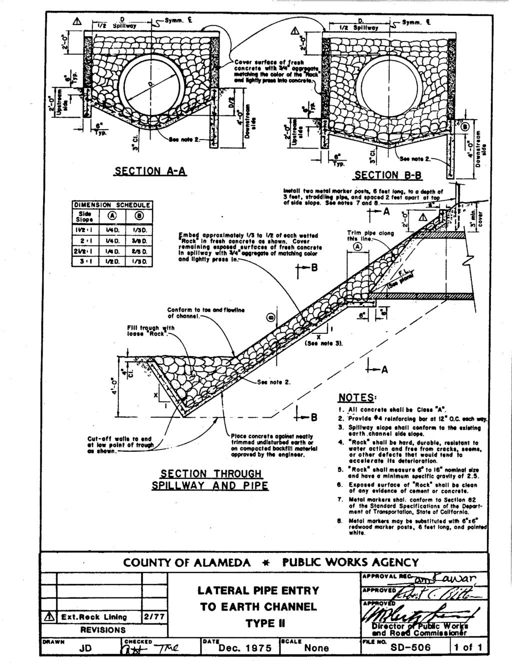
3 SD-400 SERIES DRAINAGE STRUCTURES (Continued) SD-415 7/1991 INLET TYPE V (Mod. Type I to Conform to Exist. Gutter & Top of Curb & Set Gutter Elevation) SD-416 7/1991 INLET TYPE VI SD-417 4/1976 DROP INLET TYPE E AND E-1 SD-418 7/1991 DROP INLET TYPE G SD-419 1/1995 DROP INLET WITH TAPER SD /1994 DROP INLET WITHOUT TAPER SD-421 4/1993 DROP INLET SECTION B-B SD-422 6/1993 CONVERT EXISTING DROP INLET TO MANHOLE SD-423 8/1992 FIELD INLET TYPE I (12 Sewer Pipe) SD-424 5/1993 FIELD INLET TYPE II (Poured Top on Sewer Pipe) SD-425 7/1993 FIELD INLET TYPE III (Square Poured Shaft with Bridge Deck Grate) SD-426 7/1993 FIELD INLET TYPE IV (Removable Top Slab) SD-427 9/1993 FIELD INLET TYPE V SD-428 1/1995 FIELD INLET SD-434 3/1993 BICYCLE TYPE FRAME AND GRATE (2 Sheets) SD-435 3/1995 MODIFIED DROP INLET SD-436 1/1995 FRAME AND COVER ADJUSTMENT DETAIL SD-500 SERIES MISCELLANEOUS STRUCTURES SD-500 1/1993 STRAIGHT HEADWALL TYPE A SD-501 3/1993 HEAD AND WINGWALL TYPE B SD-502 4/1976 L HEADWALL TYPE D SD-503 1/1995 REINFORCED CONCRETE CHANNEL 1:1 SIDE SLOPE SD-504 3/1994 TYPICAL PIPE SECTION (2 Sheets) SD /1970 LATERAL PIPE ENTRY TO EARTH CHANNEL TYPE I (Concrete) SD /1994 LATERAL PIPE ENTRY TO EARTH CHANNEL TYPE II (Embedded Rock) SD-507 5/1973 LATERAL PIPE ENTRY TO EARTH CHANNEL TYPE III (8 Pipe or Smaller) SD-508 7/1992 PIPE ENTRY CONCRETE LINED CHANNEL (Trapezoidal Lining) SD /1994 LATERAL PIPE CONNECTION TYPE I (Pipe to Pipe) SD-510 1/1984 LATERAL PIPE CONNECTION TYPE II SD-511 1/1995 SANITARY SEWER CROSSING SD-512 1/1995 REINFORCING STEEL PLACEMENT AT CURVED ALIGNMENT SD /1994 SIDEWALK DRAIN SD-514 8/1969 JUNCTION BOX (Checker Plate Cover) SD-515 9/1981 METAL STEP DETAIL TYPE I (Trapezoidal Lining) SD-516 3/1995 METAL STEP DETAIL TYPE III (Manhole Not Staggered) SD-517 1/1995 DELETED SD-518 6/1994 JOINT AND DOWEL DETAILS SD-519 1/1995 MANHOLE RISER RING TYPE I SD-520 1/1995 REINFORCED CONCRETE PIPE COLLAR SD-521 1/1995 BOLT DOWN DETAIL FOR MANHOLE FRAME & COVER SD-522 3/1995 CONTRACTION JOINTS SD-523 3/1995 SIMULATED STONE PATTERN CONCRETE FORM SD-524 3/1995 SIMULATED STONE PATTERN LAYOUT VARIOUS WALL HEIGHTS (3 Sheets) SD-525 6/1994 MAILBOX DETAILS (2 Sheets) SD-526 3/1985 TREE WELLS (3 Sheets) SD /1994 SIDEWALK DRAIN TYPE II SINGLE FAMILY RESIDENTIAL LOTS SD-528 1/1994 METAL STEP AND HAND POST DETAIL FOR VERTICAL CONCRETE WALLS POO-SPEC-Design Guidelines Table of Contents 2 August 2008
4 SD-600 SERIES MONUMENTS SD-600 7/1992 CONCRETE MONUMENT SECTION WITHOUT DISC SD-601 2/1994 MONUMENT DISC SD-602 2/1994 CONTROL MONUMENT DISC SD-603 2/1994 TRACT MONUMENT DISC SD-604 7/1992 CONCRETE MONUMENT SECTION WITH DISC SD-700 SERIES SIGNING DETAILS SD /1994 SIGN MOUNTING DETAILS (2 Sheets) SD-701 7/1994 BICYCLE ROUTE SIGN SD-702 8/1994 STREET NAME SIGN INSTALLATION DETAIL SD-703 9/1994 R-49 SIGN MOUNT SD-704 1/1995 SIGN POST BLOCKOUT HOLE DETAIL SD-705 3/1995 RIGID CONDUIT STUB DETECTOR LEAD IN SD /1992 TYPICAL RUMBLE STRIP INSTALLATION (2 Sheets) SD-707 2/1994 SIGNING NON-COUNTY MAINTAINED ROAD (2 Sheets) SD-708 1/1994 ACFC & WCD PROJECT SIGN SD /1992 PAVEMENT MARKER DETAILS SD /1992 ESTUARY SPEED LIMIT SIGN SD-800 SERIES BARRICADES SD-800 1/1995 CHAIN-LINK FENCE & GATES 6-FOOT HIGH SD-801 1/1995 CHAIN-LINK FENCE & GATES 4-FOOT HIGH SD-802 6/1994 STEEL DRIVE GATE (Farm Stockyard Gate) SD-803 3/1969 WOVEN-WIRE FENCE (Hog Wire With Barbed Wire Top) SD-804 3/1969 BARBED-WIRE FENCE & GATES SD-805 5/1973 METAL POST INSTALLATION SD /1981 WROUGHT IRON FENCE SD-807 4/1976 TIMBER BARRICADE SD-808 5/1993 METAL BEAM GUARD RAIL (3 Sheets) SD-809 4/1976 QUARRY FENCE POO-SPEC-Design Guidelines Table of Contents 3 August 2008
5
6
7
8
9
10
11
12
13
14
15
16
17
18
19
20
21
22
23
24
25
26
27
28
29
30
31
32
33
34
35
36
37
38
39
40
41
42
43
44
45
46
47
48
49
50
51
52
53
54
55
56
57
58
59
60
61
62
63
64
65
66
67
68
69
70
71
72
73
74
75
76
77
78
79
80
81
82
83
84
85
86
87
88
89
90
91
92
93
94
95
96
97
98
99
100
101
102
103
104
105
106
107
108
109
110
111
112
113
114
115
116
117
118
119
120
121
122
123
124
125
126
127
INSTRUCTIONS: 1. Record the transmittal letter number, date, and subject on the transmittal record sheet located in the front of the manual.
 MINNESOTA DEPARTMENT OF TRANSPORTATION DEVELOPED BY: Design Standards ISSUED BY: Office of Technical Support Design Services Section TRANSMITTAL LETTER NO. (0-03) MANUAL: Standard Plates DATED: September
Manhole or Catch Basin Type A & B Cone Sections Precast - Design F Manhole or Catch Basin Cover (Reducer Cone Section Precast) Design D
 Design D") MINNESOTA DEPARTMENT OF TRANSPORTATION DEVELOPED BY: Design Standards ISSUED BY: Office of Program Management and Technical Support, Design Support Section TRANSMITTAL LETTER NO. (14-02) MANUAL: Standard
MINNESOTA DEPARTMENT OF TRANSPORTATION DEVELOPED BY: Design Standards ISSUED BY: Office of Program Management and Technical Support, Design Support Section TRANSMITTAL LETTER NO. (14-02) MANUAL: Standard
Standard Plate 7036 is discontinued. It is replaced by Standard Plan Pedestrian Curb Ramp Details.
 DEVELOPED BY: Design Standards ISSUED BY: Office of Program Management & Technical Support, Design Support Section TRANSMITTAL LETTER NO. (12-02) MANUAL: Standard Plates DATED: May 11, 2012 SUBJECT: Standard
2. Remove from the Standard Plate manual: Standard Plate Index, Sheets 1-4 of 4, Numerical Index of Standard Plates (August 31, 2012)
") MINNESOTA DEPARTMENT OF TRANSPORTATION DEVELOPED BY: Design Standards ISSUED BY: Office of Program Management & Technical Support, Design Support Section TRANSMITTAL LETTER NO. (12-04) MANUAL: Standard
MINNESOTA DEPARTMENT OF TRANSPORTATION DEVELOPED BY: Design Standards ISSUED BY: Office of Program Management & Technical Support, Design Support Section TRANSMITTAL LETTER NO. (12-04) MANUAL: Standard
SUBJECT: Standard Plate 9102 Turf Establishment Areas At Pipe Culvert Ends
 MINNESOTA DEPARTMENT OF TRANSPORTATION DEVELOPED BY: Design Standards ISSUED BY: Office of Project Management and Technical Support, Design Support Section TRANSMITTAL LETTER NO. (17-03) MANUAL: Standard
SUBJECT: Standard Plate Turf Establishment Areas (at Pipe Culvert Ends)
") MINNESOTA DEPARTMENT OF TRANSPORTATION DEVELOPED BY: Design Standards ISSUED BY: Office of Program Management and Technical Support, Design Support Section TRANSMITTAL LETTER NO. (14-01) MANUAL: Standard
MINNESOTA DEPARTMENT OF TRANSPORTATION DEVELOPED BY: Design Standards ISSUED BY: Office of Program Management and Technical Support, Design Support Section TRANSMITTAL LETTER NO. (14-01) MANUAL: Standard
Current Standard Plates including Transmittal Letters are available on the web at:
 MINNESOTA DEPARTMENT OF TRANSPORTATION DEVELOPED BY: Design Standards ISSUED BY: Office of Project Management and Technical Support, Design Support Section TRANSMITTAL LETTER NO. (17-04) MANUAL: Standard
SUBJECT: Standard Plates 4132, 4155, Drainage Structures and Castings Info
 MINNESOTA DEPARTMENT OF TRANSPORTATION DEVELOPED BY: Design Standards ISSUED BY: Office of Project Management and Technical Support, Design Support Section TRANSMITTAL LETTER NO. (18-01) MANUAL: Standard
Miscellaneous. Demolition
 Public Improvements Miscellaneous 1 Mobilization L.S. ** 2 Clearing and Grubbing L.S. *** 3 Structural Concrete Incl. Reinforcing C.Y. $1,325.00 4 6" PVC Sleeves L.F. $26.00 Demolition 5 Remove Asphalt
STANDARD DRAWINGS INDEX MODIFIED FOR CENTRAL REGION Revised August 6, 2018
 SYMBOLS STANDARD DRAWINGS INDEX No Statewide Standard - Use Regional A3 Legend Detail Sheet BRIDGE AND STRUCTURES B-08.00 Bin Walls 1 CONSTRUCTION-BARRICADES AND SIGNING C-04.12 Location of Double Traffic
MSD STANDARD DRAWINGS LOUISVILLE AND JEFFERSON COUNTY METROPOLITAN SEWER DISTRICT 700 WEST LIBERTY STREET LOUISVILLE, KENTUCKY
 MSD M etr o p olitan S e w e r Di s t r ict STANDARD DRAWINGS LOUISVILLE AND JEFFERSON COUNTY METROPOLITAN SEWER DISTRICT 700 WEST LIBERTY STREET LOUISVILLE, KENTUCKY 40203-1911 STANDARD DRAWINGS DIVISION
PART 4 STANDARD DRAWINGS FOR CONSTRUCTION
 4.0. INTRODUCTION PART 4 STANDARD DRAWINGS FOR CONSTRUCTION In this document, Ivins City adopts the most recent edition (currently 2007), including all amendments, of the APWA Utah Chapter s Manual of
SECTION III STANDARD DRAWINGS ROYSE CITY GENERAL CONSTRUCTION NOTES & DETAILS
 9. STANDARD DETAILS SECTION III STANDARD DRAWINGS ROYSE CITY GENERAL CONSTRUCTION NOTES & DETAILS j:\clerical\royse city\1-4086 general services\168-tech const standards review\tcss manual\2018 tcss manual\sec-9a
City of Vaughan Engineering Department DESIGN STANDARD DRAWINGS
 City of Vaughan Engineering Department DESIGN STANDARD DRAWINGS March 2004 STANDARD DRAWINGS Partners With The Environment March 2004 FORWARD The March 2004 version of the City of Vaughan Design Standard
Current Standard Plates including Transmittal Letters are available on the web at:
 MINNESOTA DEPARTMENT OF TRANSPORTATION DEVELOPED BY: Design Standards ISSUED BY: Office of Project Management and Technical Support, Design Support Section TRANSMITTAL LETTER NO. (15-03) MANUAL: Standard
SUPPLEMENTARY STANDARD DETAIL DRAWINGS
 CITY OF MAPLE RIDGE DESIGN AND CONSTRUCTION DOCUMENTS Part 4 SUPPLEMENTARY STANDARD DETAIL DRAWINGS September 2015 Updated: October 2015 THIS PAGE INTENTIONALLY LEFT BLANK City of Maple Ridge Supplementary
City of Beaumont. Public Works Engineering. Street Improvement Plan Checklist REV 4/18/16
 City of Beaumont Public Works Engineering Project Name: TR: Project No.: Date: Street Improvement Plan Checklist Chk A. All Sheets 1. 24" x 36" 2. Signed by the engineer-of-work 3. Marked with the contact
Plate 8132A - Preformed Rigid PVC Conduit Loop Detector, is a new plate requested by OTST.
 DISTRIBUTION: 7 MINNESOTA DEPARTMENT OF TRANSPORTATION DEVELOPED BY: Design Standards ISSUED BY: Design Services Section TRANSMITTAL LETTER NO. (0-0) MANUAL: Standard Plates DATED: January 9, 00 SUBJECT:
CITY OF DANA POINT DEVELOPMENT REVIEW
 Section I EARTHWORK CITY OF DANA POINT DEVELOPMENT REVIEW COST ESTIMATE UNIT PRICE LIST May 2002 Page 1 of 12 Section I EARTHWORK TABLE OF CONTENTS SECTION AND TOPICS...PAGE INTRODUCTION... i I EARTHWORK...
Standard Plate Sheer Reinforcement for Precast Drainage Structures has been updated upon recommendation of the Bridge Office.
 MINNESOTA DEPARTMENT OF TRANSPORTATION DEVELOPED BY: Design Standards ISSUED BY: Office of Program Management and Technical Support, Design Support Section TRANSMITTAL LETTER NO. (13-03) MANUAL: Standard
UTILITY AND STREET CONSTRUCTION PLAN REQUIREMENTS SECTION 1
 UTILITY AND STREET CONSTRUCTION PLAN REQUIREMENTS SECTION 1 ENGINEERING STANDARDS FOR UTILITY AND STREET CONSTRUCTION PLANS MARCH 2014 CONSTRUCTION PLAN SHEET FORMAT REQUIREMENTS REPRODUCIBLE MYLAR 1.
STANDARD DETAILS Crow Canyon Road San Ramon, CA Telephone: (925) Fax: (925)
 Fax: (925)") STANDARD DETAILS 2401 Crow Canyon Road San Ramon, CA 94583 Telephone: (925) 973-2670 Fax: (925) 838-3937 CITY OF SAN RAMON STANDARD DETAILS INDEX CONCRETE WORK NAME DRAWING # Curb, Gutter & Sidewalk C-1
STANDARD DETAILS 2401 Crow Canyon Road San Ramon, CA 94583 Telephone: (925) 973-2670 Fax: (925) 838-3937 CITY OF SAN RAMON STANDARD DETAILS INDEX CONCRETE WORK NAME DRAWING # Curb, Gutter & Sidewalk C-1
Government Of Newfoundland & Labrador Municipal Water, Sewer And Roads Master Construction Specifications
 PAGE NO. : 1 OF 4 Revision Date: July 2009 STANDARD DRAWINGS TABLE OF CONTENTS DRAWING # DESCRIPTION 0030............ Work Adjacent to Roadway 0040............ Work at the Edge of Roadway 0050............
CITY OF VISTA STANDARD DRAWINGS
 CITY OF VISTA STANDARD DRAWINGS May, 2015 THIS SHEET INTENTIONALLY LEFT BLANK TABLE OF CONTENTS MODIFICATIONS Modifications to San Diego Regional Standard Drawings DRAINAGE STRUCTURES DRN 01 Corrugated
CITY OF BEVERLY HILLS Department of Public Works and Transportation Civil Engineering Division STREET/ALLEY IMPROVEMENT PLAN REVIEW CHECKLIST
 CITY OF BEVERLY HILLS Department of Public Works and Transportation Civil ing Division STREET/ALLEY IMPROVEMENT PLAN REVIEW CHECKLIST The following checklist consists of the minimum requirements for preparation
CITY OF VISTA STANDARD DRAWINGS
 CITY OF VISTA STANDARD DRAWINGS May, 2015 THIS SHEET INTENTIONALLY LEFT BLANK TABLE OF CONTENTS MODIFICATIONS Modifications to San Diego Regional Standard Drawings DRAINAGE STRUCTURES DRN 01 Corrugated
STANDARD BID ITEM NUMBERS
 10701 TRAFFIC CONTROL LUMP SUM 10702 Traffic Control for Storm Sewer Installation LUMP SUM 10703 Traffic Control for Water Main Installation LUMP SUM 10704 Traffic Control for Sanitary Sewer Installation
Please remove and replace the entire Table of Contents, Section A to Section J and all Appendices.
 Please remove and replace the entire Table of Contents, Section A to Section J and all Appendices. The following is a list of changes to the Design Criteria: 1. A2.01 General Note 4 Utility Coordination
SECTION 3 IMPROVEMENT PLAN REQUIREMENTS
 SECTION 3 IMPROVEMENT PLAN REQUIREMENTS CONTENTS Page 3-1 Digital Submittals 3-2 3-2 Paper Size and Scale 3-2 3-3 Drafting Standard 3-2 3-4 Title Sheet 3-2 3-5 Title Block 3-3 3-6 Drainage, Sewer, Water,
City of Regina Standard Construction Specification SECTION 2999 LISTING OF ROADWAY STANDARD DRAWINGS
 City of Regina Standard Construction Specification SECTION 2999 LISTING OF ROADWAY STANDARD DRAWINGS R-1 Alternate Pavement Structures July/10 R-2 Typical Cross Sections for Asphaltic Concrete Pavements
Existing and proposed contours at 1-foot intervals. The fill and/or excavation quantities in cubic yards.
 PLAN REQUIREMENTS The plans for street design shall conform to the requirements of Sections 3 and 4. The following requirements shall also be shown on the plans where applicable. Road and Storm Plans:
ROUTES: 65 SECTIONS: miles in length. THE FOLLOWING ITEMS AND APPROXIMATE QUANTITIES ARE INVOLVED:
 ARKANSAS DEPARTMENT OF TRANSPORTATION CA0801 HWY. 110 - CLINTON (WIDENING) (S) FEDERAL AID PROJECT ACNHPP-0071(31) THE PURPOSE OF THIS PROJECT IS TO WIDEN HIGHWAY 65 IN VAN BUREN COUNTY. THIS PROJECT CONSISTS
CITY OF REEDLEY NEW DEVELOPMENT PLAN REVIEW CHECK LIST
 CITY OF REEDLEY NEW DEVELOPMENT PLAN REVIEW CHECK LIST Tract Number and Subdivision Name: Engineering Firm: Contact Person: Address: City: State: Zip: Phone No. Fax No. Assessor s Parcel Number(s) Tentative
MINIMUM C/L RADII OF CURVATURE OF LOCAL ROADS IN SUBDIVISIONS
 75m 70m 65m 60m DEFLECTION ANGLE C/L RADII OF CURVATURE 55m 50m 45m 40m 35m 30m 25m 20m 15m 90 80 70 60 50 40 30 20 10 0 DEFLECTION ANGLE - MINIMUM C/L RADII OF CURVATURE OF LOCAL ROADS IN SUBDIVISIONS
PUBLIC WORKS DEPARTMENT. File: E-2000 July 11, Town of Whitby Design Criteria and Engineering Standard Drawing Revisions
 PUBLIC WORKS DEPARTMENT File: E-2000 July 11, 2011 To: All Manual Holders and Engineering Standard Drawing Revisions Please find attached a list of the revisions to the and the Engineering Standard Drawings.
CITY OF APACHE JUNCTION DEVELOPMENT SERVICES CIVIL ENGINEERING PLAN REVIEW CHECKLIST PROJECT: LOCATION:
 CITY OF APACHE JUNCTION DEVELOPMENT SERVICES CIVIL ENGINEERING PLAN REVIEW CHECKLIST PROJECT: LOCATION: LOG NO.: LEGEND REVIEW REVIEWED BY DATE / - Requirement satisfied 1 O Requirement not satisfied 2?
CITY OF LA MARQUE CHAPTER GRAPHIC REQUIREMENTS CONSTRUCTION PLAN AND MISCELLANEOUS REQUIREMENTS
 CITY OF LA MARQUE CHAPTER 2 -------------------------------------------- GRAPHIC REQUIREMENTS CONSTRUCTION PLAN AND MISCELLANEOUS REQUIREMENTS CHAPTER 2 ------------------------------------------------
STANDARD CATCH BASIN GUTTER LINE CB INLET FRAME & GRATE, GROUTED TO GRADE RINGS AS REQ'D CONCRETE CURB FINISHED GRADE ASPHALT MAX 50 MIN
 CB INLET FRAME & GRATE, GROUTED TO GRADE RINGS AS REQ'D ASPHALT 20 GUTTER LINE CONCRETE CURB FINISHED GRADE PRECAST GRADE RINGS, 2 50 100 MAX PRECAST CB LID GROUT ALL AROUND CB LEAD, INSIDE & OUTSIDE OF
CITY OF SAN MARCOS ENGINEERING DIVISION
 AN APPLICANT S GUIDE TO PROCEDURES FOR: CITY OF SAN MARCOS ENGINEERING DIVISION ENGINEER S COST ESTIMATE USING UNIT PRICES FOR BOND PURPOSES-REVISED NOVEMBER 9, 2006 (Calculations are already set-up in
CITY OF STOCKTON 2016 STANDARD PLANS AND SPECIFICATIONS PROPOSED REVISIONS
 STANDARD PLANS EXISTING ALL Proposed to Modify the outdated Standard Plans numbering system (See Attachment B) GENERAL 1 Typical Layout for Improvement Plans Added Note 7: North Arrow Location and Orientation
Washington County Road Engineering Plan Submittal/Review Checklist
 Washington County Road Engineering Plan Submittal/Review Checklist Washington County Land Use Case File Number: Parcel(s): Developer/Owner Name(s): Developer/Owner E-mail(s): The following elements should
MAINTENANCE HOLES, CATCH BASINS AND DITCH INLETS - MTC FORM 407 INDEX
 407-1 - MAINTENANCE HOLES, CATCH BASINS AND DITCH INLETS - MTC FORM 407 INDEX 407-1.1 GENERAL Tender Items Specifications Standard Drawings 407-1.1.1 Frame and Grate Selection 407-1.1.2 Selection of Structure
Appendix E-4. City of Fort Collins. Requirements for Utility Plans
 Appendix E-4 City of Fort Collins Requirements for Utility Plans Project Name: Project Planner: Design Engineering Firm: Developer: All applications for final development plans must include final development
Engineering and Construction Services Division Construction Drawings for Sewers and Watermains. T No. Revision T No. Revision Remarks All T drawings
 Engineering and Construction Services Division Construction Drawings for Sewers and Watermains Revision No. 8 April All T drawings New title block for each drawing is now standardized. Revision numbers
TYPE 4-C TYPE 6 TYPE 7 TYPE 8
 ````` Face of ase rad. 42 TYPE rad. " T T T 22.5 2'- unless otherwise shown on plans 5" 5" 5" Slope 2: TYPE 2 rad. Concrete TYPE 2-A rad. Wearing Course Concrete ase Course TYPE 2-0" rad. TYPE 3 As Shown
RAIL PANEL AT TRANSITION SECTION PLAN - POST DETAIL PLAN - TUBE SPLICE. Colorado Department of Transportation. Staff Bridge Branch
 Limits of pay length for Bridge RailType 10M (For post spacing, see Dwg. No. B ) B60610 (Use with B60610A) 8 min. 1 max. 8 min. 1 max. 10 0 Max. 10 0 Max. post spacing 10 0 Max. 2 5 Post 1 x 1 slotted
CITY OF MUSKEGO DRAFTING STANDARDS
 CITY OF MUSKEGO DRAFTING STANDARDS GENERAL - These standards apply to all plans. 1. Plans must be prepared on sheets measuring 36 inch across and 22 inch to 24 inch high unless otherwise specified under
TOWN of LAKESHORE SITE PLAN CHECKLIST
 TOWN of LAKESHORE SITE PLAN CHECKLIST Last Revised December 17, 2009 Project Name: Project Location: Date Submitted: Name Phone Number E-mail Address Owner: Contractor/ Engineer: ( ) ( ) Applicant: ( )
50.24 Type, Size and Location Plans for Culverts, Bridges and Culvert Bridges
 50.24 Culverts, Bridges and Culvert Bridges Type, Size and Location (T, S & L) Plans shall be required for all Bridges, Culvert Bridges and Culverts of eight-foot (8') clear span or greater as follows:
Pipe Product Catalog Table of Contents
 Pipe Product Catalog Table of Contents Section A: Drawing #: Page Description A1 Reinforced Concrete Pipe A3 Storm Manhole Sizing Chart (48" - 96") A3.1 Storm Manhole Sizing Chart (108" - 144") A4 48"
NEWTON COUNTY WATER AND SEWERAGE AUTHORITY RESIDENTIAL, COMMERCIAL, INSTITUTIONAL AND INDUSTRIAL SUBDIVISIONS CONSTRUCTION PLANS CHECK LIST
 NEWTON COUNTY WATER AND SEWERAGE AUTHORITY RESIDENTIAL, COMMERCIAL, INSTITUTIONAL AND INDUSTRIAL SUBDIVISIONS CONSTRUCTION PLANS CHECK LIST Project Name Checked By Date Designer Check List marks to be
SECTION 39 - MANHOLES TABLE OF CONTENTS
 SECTION 39 - MANHOLES TABLE OF CONTENTS Section Page 39-1 GENERAL... 39.1 39-2 PRECAST CONCRETE MANHOLES... 39.1 39-2.01 Precast Concrete Sewer Manholes... 39.1 39-2.02 Precast Concrete Storm Drain Manholes...
Porter County Plan Commission
 Plan Type: Development Plan Administrative DRC PC Primary Plan Administrative DRC PC Secondary Plat/Replat Administrative DRC PC PUD Conceptual Detailed Final Project Information Project Name: Developer
.1 Applicability: These criteria shall be applied as follows:
 DESIGN CRITERIA DIVISION 4800 STREET LIGHTING 4801 GENERAL: These criteria shall be adhered to for the design of all publiclyfinanced or privately-financed traffic signal systems to be installed in the
BRASELTON WATER AND WASTEWATER DEPARTMENT CONSTRUCTION PLAN REVIEW CHECKLIST May 2006
 Project Name: BRASELTON WATER AND WASTEWATER DEPARTMENT CONSTRUCTION PLAN REVIEW CHECKLIST May 2006 Phase: Unit: # Lots: Development Type (residential, commercial, industrial, etc.) Braselton Project No.
APPENDIX 4. Checklists. Township of King Design Criteria and Standard Detail Drawings
 APPENDIX 4 Checklists Township of King Design Criteria and Standard Detail Drawings Township of King Design Criteria and Standard Detail Drawings APPENDIX 4 CHECKLISTS Engineering Submissions : The following
3. DESIGN SPECIFICATIONS
 Schedule H to Bylaw 7452, Subdivision Bylaw Page 10 3. DESIGN SPECIFICATIONS 3.1 General 3.1.1 The Design Specifications apply to the design of sanitary sewers, storm drains, waterworks, roadways, and
MANHOLES PART I: GENERAL. A. Precast Concrete Manholes
 MANHOLES PART I: GENERAL A. Precast Concrete Manholes 1) Manholes shall be made of precast concrete sections of which the top section shall be eccentric or flat slab top. The bottom section shall be a
Town of Westlake Construction Plans Review Checklist
 CONSTRUCTION PLANS CONTENTS All Drawings 24 x 36 Cover Sheet Final Plat Site Plan Demolition Plan Utility Plan Drainage Area Map and Calculations Paving Plan & Profile Sheets Storm Drain Plan & Profile
Project Name: County File No.: Checked by: For: Date:
 Project Name: County File No.: Checked by: For: Date: Print name Firm or agency Items noted in the checklist shall be considered the minimum amount of information necessary for submission of construction
Bestall Collaborative Limited Planning Environment Construction Management Development
 November 18, 2017 Bestall Collaborative Limited Lori Hight, AICP, Senior Planner City Development Department City of Thornton City Hall 9500 Civic Center Drive Thornton, Colorado 80229-4326 RE: River Valley
Plan Preparation Checklist
 Appendix D Plan Preparation Checklist It is the responsibility of the Designer to complete and submit this checklist along with all required drawings for OUC (EFP) Review. All drawings submitted for OUC
Section 101. Street Design
 Section 101 Street Design This section establishes the uniform policies and procedures for the preparation of street design plans and construction requirements in the City of Irvine. It is not intended
E:\Wilmot\DGN\14018pp.dgn 3/11/2015 6:49:16 AM
 600-06 SHOULDER WIDENING FOR TYPE (SPECIAL) GUARDRAIL TERMINALS E:\Wilmot\DGN\08pp.dgn //05 6:9:6 AM E:\DGN\08SUP.dgn //05 ::55 PM E:\DGN\08SUP.dgn //05 :8:0 PM E:\DGN\08-WRG.dgn //05 :8:5 PM E:\DGN\08SM.dgn
DIVISION APPROVED MATERIAL LIST AND STANDARD DETAILS
 DIVISION 400 - APPROVED MATERIAL LIST AND STANDARD DETAILS Section 403 - STANDARD DETAILS TABLE OF CONTENTS DIVISION 400, Section 403 - STANDARD DETAILS SECTION DETAIL NOS. Application Table 403-1 I. Concrete
PROJECT NAME: TRACT, PARCEL MAP PROJECT ID NO. PLAN CHECKED BY: 1ST CHECK 3RD CHECK 2ND CHECK COMMENTS FINAL MYLAR DATE CHECKED:
 CITY OF COLTON PUBLIC WORKS/ENGINEERING DEPARTMENT STREET IMPROVEMENT PLAN REVIEW LIST (PROVIDE SEPARATE ON-SITE & OFF-SITE STREET IMPROVEMENT PLAN SETS) PROJECT NAME: TRACT, PARCEL MAP PROJECT ID NO.
M I N N E S O T A D O T BID TABULATION SUMMARY JOB PAGE 1 ON 01/14/97 MINNESOTA PROJECT NO.S: DPI 015-8(021) DPI 015-8(022)
 DPI 015-8(022)") BID TABULATION SUMMARY JOB 970010 PAGE 1 STATE PROJECT NO. 27-618-70 BIDS RECEIVED UNTIL 2:00 P.M. ON 01/14/97 MINNESOTA PROJECT NO.S: DPI 015-8(021) DPI 015-8(022) AT THE JUNCTION OF AUTO CLUB ROAD AND
BID TABULATION SUMMARY JOB 970010 PAGE 1 STATE PROJECT NO. 27-618-70 BIDS RECEIVED UNTIL 2:00 P.M. ON 01/14/97 MINNESOTA PROJECT NO.S: DPI 015-8(021) DPI 015-8(022) AT THE JUNCTION OF AUTO CLUB ROAD AND
Section E NSPS MODEL STANDARDS FOR TOPOGRAPHIC SURVEYS Approved 3/12/02
 Section E NSPS MODEL STANDARDS FOR TOPOGRAPHIC SURVEYS Approved 3/12/02 1. INTRODUCTION This standard is written to provide the professional surveyor (Surveyor) and the client with a guideline for producing
DEVELOPMENT PLAN CHECKLIST
 Project Identification Information: DEVELOPMENT PLAN CHECKLIST 1.0 GENERAL 1.1 Additional information as required by specific Land Use 1.2 All sheets to include sheet number ( of ) 1.3 Seal and signature
What Plans Do I Need for a Building Permit?
 What Plans Do I Need for a Building Permit? 6 CITY OF PORTLAND, OREGON - BUREAU OF DEVELOPMENT SERVICES 1900 SW 4th Avenue, Por tland, Oregon 97201 503-823-7300 www.portlandoregon.gov/bds This brochure
LOWNDES COUNTY ENGINEERING PLAN REVIEW CHECKLIST. Design Professional: Phone: Developer: Phone: 2 nd Submittal (No Fee)
") MEMORANDUM MICHAEL B. FLETCHER, P.E. COUNTY ENGINEER 327 N. Ashley Street Valdosta, GA 31601 Telephone: (229) 671-2424 Fax: (229) 245-5299 mfletcher@lowndescounty.com LOWNDES COUNTY ENGINEERING PLAN REVIEW
MEMORANDUM MICHAEL B. FLETCHER, P.E. COUNTY ENGINEER 327 N. Ashley Street Valdosta, GA 31601 Telephone: (229) 671-2424 Fax: (229) 245-5299 mfletcher@lowndescounty.com LOWNDES COUNTY ENGINEERING PLAN REVIEW
City of Regina Standard Construction Specifications SECTION LIST OF SEWER STANDARD DRAWINGS
 City of Regina Standard Construction Specifications SECTION 14999 LIST OF SEWER STANDARD DRAWINGS S-1 No Drawing Feb/10 S-2 Precast Manhole 1050mm Dia. July/10 S-2B Precast Manhole 1200mm Dia. Jan/17 S-3
DRAFTING STANDARDS 9.00 DRAFTING STANDARDS
 DRAFTING STANDARDS 9.00 DRAFTING STANDARDS Final plans shall conform in appearance, format, accuracy, and quality to the standards used in the Springfield Engineering Division. Additional standards shall
Revised BRIDGE REPORT AND LAYOUT PAVEMENT STRUCTURE DESIGN CHAPTER VII UTILITIES CHAPTER VIII TRAFFIC CONTROL DEVICES
 CHAPTER I CHAPTER II CHAPTER III CHAPTER IV CHAPTER V CHAPTER VI GENERAL INFORMATION PRELIMINARY DESIGN SURVEYS DETAIL DESIGN BRIDGE REPORT AND LAYOUT PAVEMENT STRUCTURE DESIGN CHAPTER VII UTILITIES Revised
Sewer Line Extension Permit Design Checklist
 CHECKLIST C1 Revised 4/7/2017 Sewer Line Extension Permit Design Checklist DISCLAIMER - This checklist is provided to Consulting Engineers for the express purpose of assisting them in compiling sewer line
B17. Sewer Site Plans BULLETIN
 BULLETIN B17 Revised 5/2/2016 Sewer Site Plans Public Works This bulletin is designed to assist you in submitting the required documentation for sewer site plans to the Pierce County Sewer Division in
CHAPTER 11. Plan Standards
 CHAPTER 11 Plan Standards A. Introduction The city requires uniform public improvement plans for ease of record keeping and understanding. The following standards govern most plan submittals to the city.
CITY OF SALEM DEPARTMENT OF PUBLIC WORKS ADMINISTRATIVE RULES CHAPTER 109 DIVISION 002 DRAFTING AND DRAWING STANDARDS
 CITY OF SALEM DEPARTMENT OF PUBLIC WORKS ADMINISTRATIVE RULES CHAPTER 109 DIVISION 002 DRAFTING AND DRAWING STANDARDS SECTION 2.1 INTRODUCTION... 1 (a) Objective...1 (b) Applicability...1 2.2 SUBMITTAL
City of Massillon Site Plan Checklist
 City of Massillon Site Plan Checklist The following information MUST be included with all Site Plans submitted for review and processing in order to constitute a complete Site Plan Package. Incomplete
STATE UNIVERSITY CONSTRUCTION FUND
 DIRECTIVE 1C-12 Issue date: August 2012 1. General SURVEY, MAPPING AND UTILITY LOCATING This Directive has been developed as a general guide for the survey and mapping effort required for Fund projects.
C-M TMR Products Index
 C-M TMR Products Index TMR Dwg. No. Grate/Frames 9x6 Dwg. AS3996 Recessed Road Gully Units Dwg. 1443, 1444 Protruded Road Gully Units Dwg. 1443, 1444 1220 Road Gully Units Dwg. 1459 7x4 Road Gully Units
EXTERIOR BUILDING, ROOFING, AND SITE IMPROVEMENTS
 CONTRACT NUMBER: IFB-8-B006 ARCHITECT / ENGINEER : HURST-ROSCHE, INC. NO. LINOIS 62203 (68) 398-0890 -7 E. RANDLE ST./ N. FRITZ ST. 402 CHERRY ST., 404-406 ST. LOUIS ST. 502-506 DEE ST. 50-505 PLUM ST.
MINIMUM DRAWING REQUIREMENTS FOR WATER AND SEWER LINE PROJECTS
 Public Works Department Water & Wastewater Services WATER & WASTEWATER ENGINEERING DIVISION 2555 West Copans Road Pompano Beach, Florida 33369 954-831-0745 FAX 954-831-0798/0925 MINIMUM DRAWING REQUIREMENTS
MH Table of Contents Standard Title/Scope Page Table of Contents SCE Public
 MH Table of Contents Standard Title/Scope MH 300 MH 310 MH 318 MH 320 MH 325 MH 330 MH 335 MH 340 MH 350 Manholes Requirements MH 300.1 Manholes Requirements...........................................
CITY OF BEVERLY HILLS Department of Public Works and Transportation Civil Engineering Division STORM DRAIN IMPROVEMENT PLAN REVIEW CHECKLIST
 CITY OF BEVERLY HILLS Department of Public Works and Transportation Civil ing Division STORM DRAIN IMPROVEMENT PLAN REVIEW CHECKLIST The following checklist consists of the minimum requirements for preparation
EXCAVATION AND BACKFILL
 Standard Specification 2565.3, 2451, and 1805 A basic understanding of specifications is needed to properly replace the disturbed soil and restore the condition of the excavated area. The size of the disturbed
MAJOR GRADING PLAN CHECKLIST
 MAJOR GRADING PLAN CHECKLIST PUBLIC WORKS DEPARTMENT / ENGINEERING DIVISION 8130 Allison Avenue, La Mesa, CA 91942 Phone: (619) 667-1166 Fax: (619) 667-1380 Grading plans shall address both rough grading
SECTION PRECAST CONCRETE SECTIONAL MANHOLES
 SECTION 02545 PRECAST CONCRETE SECTIONAL MANHOLES PART 1 - GENERAL 1.01 SUMMARY A. Section Includes: 1. Precast reinforced concrete cylindrical sectional manholes, complete with openings, inserts, hardware,
SECTION 6A ROADWAY PLAN PREPARATION
 SECTION 6A ROADWAY PLAN PREPARATION Table of Contents Page No 6A.1 GENERAL...1 6A.2 PRELIMINARY PLANS...3 6A.2.1 PRELIMINARY PLAN SHEETS...3 6A.2.2 PRELIMINARY PROFILE SHEETS...4 6A.3 PHASE A PLANS...4
Maintenance of Traffic sequence of operations including any phasing and detour maps;
 All Local-let projects are required to have a Stage 2 submittal to the LPA Manager for review. The only exceptions are 2-lane resurfacing, striping, guardrail, and raised pavement markers, unless otherwise
PRECISE GRADING PLAN CHECKLIST
 PRECISE GRADING PLAN CHECKLIST PUBLIC WORKS DEPARTMENT / ENGINEERING DIVISION 8130 Allison Avenue, La Mesa, CA 91942 Phone: 619. 667.1166 Fax: 619. 667.1380 Grading plans shall address both rough grading
List of Figures. List of Forms
 City of Columbia Engineering Regulations PART 1: SUBMISSION OF PLANS Table of Contents Paragraph Description Page No. 1.1 General 1-1 1.2 Engineer s Report 1-1 1.3 Plans 1-3 1.4 Revisions to Approved Plan
CITY OF TUMWATER 555 ISRAEL RD. SW, TUMWATER, WA (360)
") CITY OF TUMWATER 555 ISRAEL RD. SW, TUMWATER, WA 98501 (360) 754-4180 Email: cdd@ci.tumwater.wa.us WATER-SEWER-STREET-STORM (IN CITY) Submittal Checklist TUM - RCVD BY DATE STAMP APPLICANT INFORMATION
CITY OF TUMWATER 555 ISRAEL RD. SW, TUMWATER, WA 98501 (360) 754-4180 Email: cdd@ci.tumwater.wa.us WATER-SEWER-STREET-STORM (IN CITY) Submittal Checklist TUM - RCVD BY DATE STAMP APPLICANT INFORMATION
Authorized Agent: City of Manassas Check List Attached: Contact: Address: Phone Number: Fax Number: Developer s Name: Phone Number:
 CITY OF MANASSAS DEPARTMENT OF COMMUNITY DEVELOPMENT DEVELOPMENT SERVICES DIVISION 9027 Center Street Room 201 Manassas, Virginia, 20110 Phone: 703-257-8278 Fax: 703-257-5831 Application Date: APPLICANT
Grease Interceptor Design Checklist
 CHECKLIST C2 Revised 5/2/2016 Grease Interceptor Design Checklist Public Works DISCLAIMER - This checklist is provided to Consulting Engineers for the express purpose of assisting them in compiling private
580 - NOISE BARRIERS OPSS 580 INDEX
 580 - OPSS 580 INDEX 580.1 GENERAL 580.1.1 Noise Barrier Design Elements 580.1.1.1 Wind-Load Designs 580.1.1.2 Sound-Absorptive Barriers 580.1.1.3 Noise Barrier Colour, Pattern and Texture 580.1.2 Grading
CHAPTER 3 INFORMATION REQUIRED FOR PUBLIC IMPROVEMENT CONSTRUCTION PLANS TABLE OF CONTENTS
 CHAPTER 3 INFORMATION REQUIRED FOR PUBLIC IMPROVEMENT CONSTRUCTION PLANS TABLE OF CONTENTS Section Title Page 3.1 General... 3-1 3.1.1 Plan Set...3-1 A. Loveland (City Limits Only)...3-1 3.1.2 Final Mylars...3-1
NRE DESIGN PARK SITE DEVELOPMENT PLANS SECTION 3 TOWNSHIP 50 SOUTH, RANGE 25 EAST CITY OF NAPLES, COLLIER COUNTY, FLORIDA
 SITE DEVELOPMENT PLANS LEGAL SUBJECT PROPERTY SECTION 3 TOWNSHIP 50 SOUTH, RANGE 25 EAST CITY, COLLIER COUNTY, FLORIDA PROPERTY OWNER: ENTERPRISE PLAZA LLC 404 CITATION PT, FL 34104 GULF MEXICO PREPARED
B.2 MAJOR SUBDIVISION PRELIMINARY PLAN CHECKLIST
 B.2 MAJOR SUBDIVISION PRELIMINARY PLAN CHECKLIST YES* GENERAL SUBMISSION ITEMS Does the submission include: 1. Thirteen (13) copies of completed Application Form? 2. Thirteen (13) copies of the Preliminary
City of Starkville Development Review Committee Infrastructure Drawings Submittal Checklist for Site Plan Applications
 City of Starkville Development Review Committee Infrastructure Drawings Submittal Checklist for Site Plan Applications Please submit ten (10) folded copies of the Infrastructure Drawings along with this