TYPE 4-C TYPE 6 TYPE 7 TYPE 8
|
|
|
- Imogen McDaniel
- 5 years ago
- Views:
Transcription
1 ````` Face of ase rad. 42 TYPE rad. " T T T '- unless otherwise shown on plans 5" 5" 5" Slope 2: TYPE 2 rad. Concrete TYPE 2-A rad. Wearing Course Concrete ase Course TYPE 2-0" rad. TYPE 3 As Shown on Typical Sections in Plans 2'- unless otherwise shown on plans Slope 2: As Shown on Typical Sections in Plans Ashphalt Concrete As Shown on Typical Section in Plans 2 2 T T T 0" rad. Concrete TYPE 3-A 0" rad." Wearing Course ' Concrete ase Course TYPE 3-2'- unless otherwise shown on plans 5" 5" rad. Slope 2: As Shown on Typical 5" Sections in Plans TYPE 4 rad. Concrete TYPE 4-A rad. Wearing Course Concrete ase Course TYPE 4- As Shown on Typical Section in Plans 2 As Shown on Typical Section in Plans 8" " rad. Earth Preformed Joint Material, Item " " rad. 5" Joint Sealer 5" Asphalt or Shoulder " " rad. Joint Sealer / Approach Slab Preformed Joint Material, Item TYPE 4-C " rad. TYPE 6 6 " TYPE 7 " TYPE 8 8" Joint Sealer " " " Preformed Joint Material, Item " " " rad. " rad. Joint Sealer Preformed Joint Material, Item and concrete bases. NOTES GENERAL: This drawing shows alternate types of curb that may be used on various types of pavement. The typical section of the project shows the type to be used, also the thickness of the edge of the pavement or the edge of the curb and gutter section. JOINTS: " expansion joints shall extend up to the top of the curb and shall be constructed in the curb and gutter section in such a manner that the joint seal will extend the full width of the gutter and into the curb face a sufficient distance to seal the joint to an elevation of a least above the flow line of the gutter. Dowel bars shall be used in the curb and gutter section at expansion joints and to the surface of the pavement. Transverse expansion joint material shall meet the requirements of Item GUTTER PLATE THICKNESS: Thickness of gutter plate "T" shall be unless otherwise shown on the plans. TOLERANCES: Dimensional tolerances are as follows: - s: 3 to + ". Gutters: 0 to + ". LEGEND Expansion joint material and joint sealer are not required for the portion of the curb that is adjacent to a flexible pavement type. oth materials are required, as detailed, for the full height of rigid pavement 2 utt joints shall be provided between combined curb-and-gutter and new or existing rigid pavements, with tie bars or hook bolts provided at intervals of 5'. See SCD P-2. for details of tie bars and hook bolts. If the combined curb-and-gutter adjoins a new rigid base or an existing rigid base or pavement that is to be surfaced with bituminous material, a butt joint shall also be provided. However, tie bars or hook bolts shall be omitted when the vertical overlap ("V" in detail below) between the curb-and-gutter and rigid pavement is less than 7". Combined curb-and-gutter V ituminous Surface Material Rigid THIS DRAWING REPLACES P-5.DATED STDS. STATE OF OHIO DEPARTMENT OF REVISION DATE STANDARD ROADWAY CONSTRUCTION DRAWING SCD NUMER TRANSPORTATION ADMINISTRATOR ENGINEER RO A D W A Y C O NC RETE C URS A ND C O M INED CUR A ND G UTTER Michael line P-5. M. Ruppe
2 Construct each curb ramp using Type A details on Sheet 2. Use curb ramps with flared sides at locations with wide sidewalks. Construct each curb ramp using Type A2 details on Sheet 2. Construct each curb ramp using Type A details on Sheet 2. uffer Two sets of Double Parallel s are shown. Use curb ramps with returned curbs where buffer is wide enough to accommodate ramp slope. Place on streets having wide turning radius and where sidewalks are narrow. PERPENDICULAR CUR RAMPS PARALLEL CUR RAMPS PREFERRED CONSTRUCTION PLACEMENT 5'-0" min. Radial Radial Construct each curb ramp using Type C details on Sheet 2. 5'-0" min. Radial ramp placement where streets have wide turning radius, and sufficient sidewalks width. COMINATION CUR RAMPS Radial STDS. STATE OF OHIO DEPARTMENT OF REVISION DATE ENGINEER TRANSPORTATION ADMINISTRATOR RO A D W A Y M. Ruppe Reynaldo Stargell NOTES uffer GENERAL: This drawing shows curb ramp types details and placement examples for curb ramp construction, including the installation of detectable warnings. ramp types are shown on Sheet 2 and include Perpendicular, Parallel, and Combined types as specified to be constructed in the locations shown on the project plans. ramps added to an existing intersection or walk should be individually detailed on the project plans to assure that the design is appropriate for site constraints and all items can be constructed to ADA standards. The contractor may adjust the placement of curb ramps if existing field conditions warrant with the approval of the Engineer. PAYMENT: Measure and pay for the ramp area within the shaded limits of this drawing as Item 608, Square Foot. This includes the cost of any curb or curb and gutter, detectable warnings, landing areas and any additional materials, installation, grading, forming, and finishing required within the shaded area. Work beyond the shaded ramp/landing area is paid for as curb (609) and walk (608). Removal of existing curb, walk (or existing curb ramps) are paid under Item 202. For at-grade crossing locations where only detectable warnings are required in order to acheive ADA compliance, measure and pay for the strip of detectable warnings as Item 608 Detectable Warning, Square Foot. The work to cast the tiles in place will also require removal of existing pavement (Item 202) to the nearest joint, or if no joint exists, a minimum of 4 feet. '-0" min. Radial Radial Widening (ypass) When Required Clear Space Cross- Construct each curb ramp using Type A details on Sheet 2. Use this design only for existing walks, and when site Acceptable design on corners with wide constraints prohibit other designs. The diagonal Type turning radius where user is able to D ramp may be constructed as either a Perpendicular, maneuver within crosswalk limits so as not Parallel or Combination curb ramp type. Avoid using to encroach into adjacent traveled lanes. where curb radii are less than 20'-0". PERPENDICULAR RAMPS DIAGONAL RAMP (Type D) ACCEPTALE CONSTRUCTION PLACEMENT walk Acceptable design for retrofit only where utilities prevent using a preferred layout. 2: Landing THIS DRAWING REPLACES P-7.DATED STANDARD ROADWAY CONSTRUCTION DRAWING SCD NUMER NEW C UR RA M PS (w ith D etectable W arnings) P-7. ````` 3
3 A 0: 2: 0: Height A Type A (Perpendicular with flared sides) Landing PERPENDICULAR CUR RAMP DETAILS uffer 2: '-0" min. Landing Type A2 (Perpendicular with returned curb) Height NOTES CONTINUED The running slope of the ramp is preferred to be 2: or flatter. In existing sidewalks, where the maximum ramp slope is not feasible due to site constraints (e.g. utility poles or vaults, right-of-way limits) it may be reduced as follows: A) 0: for a rise of, ) 8: for a rise of, C) 6: over a run of 2'-0" for historic areas where a flatter slope is not feasible. To prevent chasing the grade indefinately, the transition from exisiting sidewalk to the shaded curb ramp area is not required to exceed 5 feet in length. While ramps may be skewed to the crosswalk, the entire lower landing area must fall within the cross walk that the ramp serves and cannot be located in the traveled lane of opposing traffic. The counter slope of the gutter or street at the foot of a curb ramp, landing, or blended transitions shall be 20: ot flatter. The bottom edge of the ramp shall change planes perpendicular to the landing. The edge of the curb shall be flush with the edge of the adjacent pavement and gutter and surface slopes that meet grade breaks shall also be flush. STDS. STATE OF OHIO DEPARTMENT OF REVISION DATE ENGINEER TRANSPORTATION ADMINISTRATOR Reynaldo Stargell M. Ruppe landings shall be 4' min. x 4' min. with a or flatter cross slope and running slope. Slope '-0" min. C Grass 2: 0: 2: C 2: 0: Type C (Combined with flared sides) Landing COMINED CUR RAMP DETAILS Type (Single sided Parallel) Height Height Landing Grass 2: PARALLEL CUR RAMP DETAILS uffer 2: 2: 2: Grass 2: Type C2 (Combined with returned curb) Landing '-0" min. Type 2 (Double sided Parallel) Landing Height Height 2: D DETECTALE WARNINGS: Install Detectable Warnings on each curb ramp with approved materials, as shown on Sheet 3. Install these proprietary products as per manufacturer's written instructions. DRAINAGE: Contractor is to ensure the base of each constructed curb ramp allows for proper drainage, without exceeding allowable cross slope or ramp slopes. Vertical change in level exceeding " between the ) pavement and gutter, and 2) gutter and ramp, are not allowed. SURFACE TEXTURE: Texture concrete surfaces by coarse brooming transverse to the ramp slopes to be rougher than the adjacent walk. JOINTS: Provide expansion joints in the curb ramp as extensions of walk joints and consistent with Item requirements for a new concrete walk. Provide a " Item expansion joint filler around the edge of ramps built in existing concrete walks. Lines shown on this drawing indicate the ramp edges and slope changes, and do not necessarily indicate joint lines. Height Follows Slope of the Grass 2: Grade reak See Sheet 3 for Sections. Type 3 (Single sided Parallel) Height '-0" min. D THIS DRAWING REPLACES P-7.DATED STANDARD ROADWAY CONSTRUCTION DRAWING SCD NUMER RO A D W A Y NEW C UR RA M PS (w ith D etectable W arnings) P-7. ````` 2 3
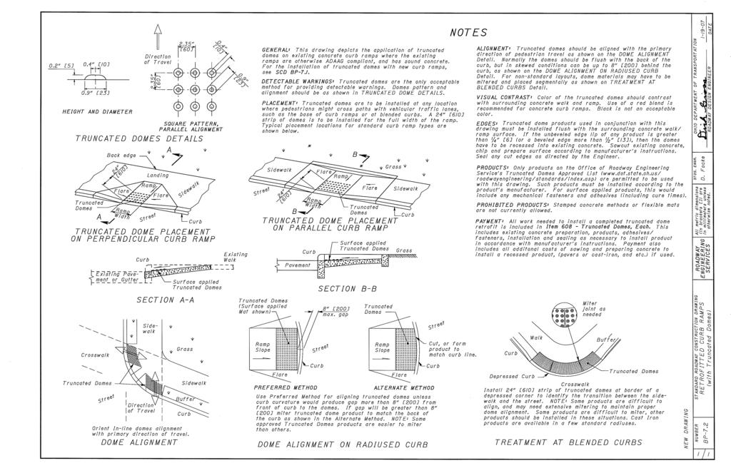
4 ````` " Item Wide Concrete 20: 2'- Gutter 2: Slope 2: Slope New gutter shown. SECTION A-A NORMAL DETAIL See Sheet 2. min. '- 2: Slope '- min. SECTION D-D See Sheet 2. Landing Slope 2 Wide Concrete 4'-0" *Where possible, pour ramp area integral with the curb, otherwise use thick walk. DETECTALE WARNINGS NOTES ment or Gutter GENERAL: Detectable Warnings are a distinctive surface pattern of truncated domes which are detectable by cane or underfoot to alert people with vision impairments of their approach to streets and hazardous drop-offs. PLACEMENT: Detectable warnings are to be installed at any location where pedestrians might cross paths with vehicular traffic lanes, such as the base of curb ramps or at blended curbs. A 2 strip of domes is ALIGNMENT: Truncated domes should be aligned with the primary direction of the ramp as shown on the DETECTALE WARNING ALIGNMENT Detail. Normally Detail A Remove Existing Saw Cut if is Monolithic with or Gutter to be installed for the full width of the ramp or walk. Typical street corner placement locations are shown on Sheet. The depth of concrete underneath detectable warning products shall be a minimum of. See DETAIL A. the detectable warnings should be flush with the back of the curb, but for skewed conditions see DETECTALE WARNING ALIGNMENT Detail. For non-standard layouts, detectable warning materials may have to be mitered and placed PRODUCTS & COLORS: Color of the detectable warnings should contrast with sursegmentally. rounding concrete walk and ramp. lack is not an acceptable color. Approved products and guidance on color may be found on the Office of Roadway Engineering Service's Detectable Warnings Approved List. Install products as per manufacturer's printed instructions. 2 Wide Concrete Adjacent to P.C.C. - " Preformed Joint Material Item with Joint Sealer Applied per SCD P-5. SECTION A-A EXISTING WALK DETAIL See Sheet 2.. min. 2. '- Surface. min. 2. min. Meet Existing " verify slope Existing Walk Use Manufacturer's Written Instructions for Installing Weep Holes, Setting ed and Grouting Method 0. SQUARE PATTERN, PARALLEL ALIGNMENT " Item DETAIL A 0. min.. HEIGHT AND DIAMETER 0. min.. Direction of Existing 50% to 65% of ase Diameter 2.. min. Detectable 2 Wide Concrete Warning Plate. min. 2. TRUNCATED DOMES DETAILS 2: Slope '- SECTION - Depth Varies min. Landing Slope See Sheet 2. See Sheet 2. min. Concrete RADIAL ALIGNMENT 0. min.. Detectable Warnings in Line with Truncated Domes Slope Flare Exceeds 5' 2 2 Wide Concrete Grade reak Slope '- SECTION C-C DETECTALE WARNING ALIGNMENT walk Existing Pave- Sidelanding 4' min. Clear Space Truncated Domes Slope Flare DOME ALIGNMENT ON RADIUSED CUR 2 5' min. '-0" Grass uffer THIS DRAWING REPLACES P-7.DATED STDS. STATE OF OHIO DEPARTMENT OF REVISION DATE STANDARD ROADWAY CONSTRUCTION DRAWING SCD NUMER TRANSPORTATION ADMINISTRATOR ENGINEER RO A D W A Y NEW C UR RA M PS (w ith D etectable W arnings) Reynaldo Stargell P-7. M. Ruppe 3 3
5
6 Top of curb " exp. joint Drop gutter in 20' from each side of catch basin for normal transverse slope, and " within blockout for combined curb and gutter. Frame & grates casting S6x2.5x6'`" Top of curb " exp. joint Location of grate, elev.,. station and offset Normal pavement slope Depressed pavement Reinf. steel per SCD P-. face " A Top of curb & casting ack of curb anchor bolt STATE OF OHIO DEPARTMENT OF TRANSPORTATION STATE HYDRAULIC ENGINEER Steel eam " Dowel Reinf. steel per SCD P-. '-0" Permissible construction joint min. Outlet pipe location to meet project requirements Permissible construction joint '-0" " Dowel The bottom may be precast separately and the outlet pipe placed on top of it with the bottom shaped to drain Permissible constr. joint '-0" S6x2.5x6'`" Steel eam 8 " " min. Variable depth REVISIONS ROADWAY HYDRAULIC ENGINEER Matt Cozzoli min. bottom A 8" 4'- 8" 8" 2'- 8" SECTION A-A 2'-5 " 2'-5 " Location of grate elevation, station and Grate (icycle Safe Shown) Dowel location for curb & gutter SECTION - WITH CUR ( DEPRESSION) face HY D RA ULIC ack of curb offset ack of curb 2'-0" Gutter " exp. joint Cap " Dowel 45 Combination curb and gutter blockout X " " " exp. joint Direction of flow for grates as shown " Dowel 2'-0" min. Location of grate, elev.,. station and offset Normal gutter elevation Depressed gutter " " STANDARD HYDRAULIC CONSTRUCTION DRAWING C A TC H A SIN NO. 3 block out for straight transverse slope utt joint Outside of conc. basin SECTION - WITH CUR & GUTTER ( " DEPRESSION) PLAN OF CATCH ASIN AND PAVEMENT JOINTS CATCH ASIN No. 3 See Sht. 2/2 for NOTES SCD NUMER C -2. 2
7 '- 9 5 " '-4 '-4 '-4 '-4 " bolt hole " rad. Finished DUMP NO WASTE DRAINS TO WATERWAY 6 " 4'-8 3 " '-0 " NOTES GRATES: Two required. For details, see SCD C-2.2. Provide Grate "V" unless the plans specifically require the diagonal grate. If the diagonal grate is specified, place it so that the diagonal bars direct drainage flow toward the curb. CASTINGS: Provide a design essentially the same and equally as strong as the one shown. Minimum weight: Casting lbs. Two Grates lbs. Frame lbs. Two Grate "V" lbs. Lighter weight frames and grates that meet the requirements of CMS 7.4 may also be provided. Provide grate openings and dimensions as shown here unless otherwise shown in the plans. STATE OF OHIO DEPARTMENT OF TRANSPORTATION STATE HYDRAULIC ENGINEER 6'-" PLAN & SECTION rad. 5'- PLAN Cast the following text into the top of the curb casting: "DUMP NO WASTE" and "DRAINS TO WATERWAY" Print text in bold, capital letters at least high. See example on Plan & Section. "WATERWAY" may be substituted with "STREAM", "RIVER", "LAKE", etc. Actual placement and logo may vary per manufacturer. REVISIONS " rad. 5'-" " rad. Finished 2'-6 " EARING AREAS: Fit and finish the frame and grate to provide a firm and even seat. No projections are permitted on bearing areas, and the grate must seat in its frame without rocking. ROADWAY HYDRAULIC ENGINEER Matt Cozzoli " " WALLS: When used in place of concrete, construct brick side walls with 8" nominal thickness. " rad. '-4 '-4 '-4 '-4 6'-" FRONT VIEW & SECTION 7 " 5'- FRONT VIEW PRECAST CONSTRUCTION: Permitted, except for the apron. Meet CMS concrete requirements. Provide precast walls at least thick with sufficient reinforcing to permit shipping and placement without damage. Reduce the wall thickness from the outside. MINIMUM DEPTH: The minimum depth is per the cover requirements for that pipe type. OPENINGS: Ensure pipe openings are the O.D. of the pipe being supplied plus when fabricated or field cut. Fill any voids per C&MS 6. DOWELS: Furnish four "x8" dowels for concrete pavement or gutter blockout. See SCD P-2.2 for dowel details. HY D RA ULIC " rad. " rad. " rad. 7 " " CUR CASTING '-6 '-5" '-2 " " 5 " 9Œ" rad. 5 " 2'-6 " " " 3 " rad. " rad. LOCKOUT: Pave blockouts with 4000 psi compressive strength concrete in PCC pavement or gutter. lockouts are paid for as part of the pavement or gutter with no deduction in pavement, curb or gutter quantities because of the castings. Cast a 4000 psi compressive strength concrete apron, the size of the 2'-0" gutter blockout, in place in asphalt pavement (no dowels required) with the cost included in the catch basin bid price. No deduction is made in curb quantities. PAYMENT: All materials and labor, including excavation and backfilling, are paid for under Item 6 - Catch asin, No. 3. STANDARD HYDRAULIC CONSTRUCTION DRAWING C A TC H A SIN NO. 3 6 " 4'-8 rad. " ACK VIEW 2'-0 " END VIEW FRAME FRAME SCD NUMER C
8 Drop gutter in 20' from each side of catch basin for normal transverse slope, and " within blockout Top of for combined curb and gutter. curb " exp. joint casting Frame & grate S6x2.5x3'-`" Permissible '-0" constr. joint '-0" " Dowel Reinf. steel per SCD P-. The bottom may be precast separately min. " exp. joint Location of grate, elev., " Dowel station and offset Normal pavement slope Depressed pavement Reinf. steel per SCD P-. Permissible constr. joint '-0" face " A 8 " S6x2.5x3'-`" " Top of curb and casting ack of curb or height of curb min. Variable depth as shown in the plans. NOTES GRATES: One required. For details, see SCD C-2.2. Provide Grate "V" unless the plans specifically require anchor bolt the diagonal grate. If the diagonal grate is specified, place it so that the diagonal bars direct drainage flow toward the curb. CASTINGS: Provide a design essentially the same and equally as strong as the one shown. Minimum weight: Casting lbs. Standard Grate lbs. Frame lbs. Grate "V" lbs. Lighter weight frames and grates that meet the requirements of CMS 7.4 may also be provided. Provide grate openings and dimensions as shown here unless otherwise shown in the plans. STATE OF OHIO DEPARTMENT OF TRANSPORTATION REVISIONS STATE HYDRAULIC ENGINEER min. bottom and the outlet pipe placed on top of it with the bottom shaped to drain. Cast the following text into the top of the curb casting: "DUMP NO WASTE" and "DRAINS TO WATERWAY" ROADWAY HYDRAULIC ENGINEER Matt Cozzoli A Print text in bold, capital letters at least high. See example on Plan & Section. "WATERWAY" may be substituted with "STREAM", "RIVER", "LAKE", etc. Actual placement and logo may vary per manufacturer. 8" 2'- 8" Dowel location for curb & gutter 8" 2'- 8" EARING AREAS: Fit and finish the frame and grate to provide a firm and even seat. No projections are Cap " exp. joint ack of curb SECTION A-A C " Dowel 2'-5 " X D D 45 Combination curb and gutter blockout Location of grate elevation, station and offset Outside of conc. basin " " C Grate (icycle Safe Shown) ack of curb Direction of flow for grate as shown 2'-0" min. Cap SECTION - WITH CUR ( DEPRESSION) 2'-0' Gutter " Normal gutter elevation Depressed gutter face Location of grate, elev., sta. and offset " permitted on bearing areas, and the grate must seat in its frame without rocking. WALLS: When used in place of concrete, construct brick side walls with 8" nominal thickness. PRECAST CONSTRUCTION: Permitted, except for the apron. Meet CMS concrete requirements. Provide precast walls at least thick with sufficient reinforcing to permit shipping and placement without damage. Reduce the wall thickness from the outside. MINIMUM DEPTH: The minimum depth is per the cover requirements for that pipe type. OPENINGS: Ensure pipe openings are the O.D. of the pipe being supplied plus when fabricated or field cut. Fill any voids per C&MS 6. DOWELS: Furnish four "x8" dowels for concrete pavement or gutter blockout. See SCD P-2.2 for dowel details. LOCKOUT: Pave blockouts with 4000 psi compressive strength concrete in PCC pavement or gutter. lockouts are paid for as part of the pavement or gutter with no deduction in pavement, curb or gutter quantities because of the castings. Cast a 4000 psi compressive strength concrete apron, the size of the 2'-0" gutter blockout, in place in asphalt pavement (no dowels required) with the cost included in the catch basin bid price. No deduction is made in curb quantities. PAYMENT: All materials and labor, including excavation and backfilling, are paid for under Item 6 - Catch asin, No. 3A. STANDARD HYDRAULIC CONSTRUCTION DRAWING C A TC H A SIN No. 3A HY D RA ULIC blockout for straight transverse slope utt joint " exp. joint SECTION - WITH CUR & GUTTER ( " DEPRESSION) PLAN OF CATCH ASIN AND PAVEMENT JOINTS (For SECTIONS C-C and D-D, see Sht. 2/2) SCD NUMER C -2.2 CATCH ASIN No. 3A 2
9 0 2 " '-0 " 2'- 3'- 6 " 3 " " SECTION D-D (See Sht. /2.) 2'-5 " " " Grate size 2'-5 " x '-4 " x " " radii all bar edges 3 " rad " " rad. '-4 Y SECTION Y-Y Direction of flow for grate as shown 2'-5 " 2 Y " " STATE OF OHIO DEPARTMENT OF TRANSPORTATION REVISIONS STATE HYDRAULIC ENGINEER PLAN SECTION C-C DIAGONAL GRATE (See Sht. /2) " PLAN GRATE "V" ROADWAY -5-6 HYDRAULIC ENGINEER Matt Cozzoli 2'-6 " '- '-6 " 3 " " bolt hole " rad. " '-5" '-2 " " 5 " 6 " 2'- " rad. " rad. '- 9 5 " DUMP NO WASTE Finished DRAINS TO WATERWAY " rad. " rad. 7 " rad. " 5 " 9Œ" rad. HY D RA ULIC 7 " ACK VIEW 2'-6 " " 3 " 3'- PLAN 2'- " rad. rad. (internal) 2'-0 " END VIEW FRAME 9 5 " " rad. " rad. STANDARD HYDRAULIC CONSTRUCTION DRAWING C A TC H A SIN No. 3A Finished '- " rad. " 3'- FRAME 3'- FRONT VIEW END VIEW bolt hole SCD NUMER C -2.2 FRONT VIEW CUR CASTING CUR CASTING 2 2
10 Gutter frame Edge of concrete and grate A " exp. joint apron for basins without curbs Location of grate, elev., station and offset ack of curb " exp. joint A NOTES GRATE AND FRAME: Provide a design essentially the same and equally as strong as the one shown (see construction information table), or meet the requirements of CMS 7.4. Provide grate openings and dimensions as shown here unless otherwise shown in the plans. Cast the following text into the top of the grate: "DUMP NO WASTE" and"drains TO WATERWAY" Print text in bold, capital letters at least " high. "WATERWAY" may be substituted with "STREAM", "RIVER", "LAKE", etc. Actual placement and logo may vary per manufacturer. EARING AREAS: Fit and finish frame and grate to provide a firm and even seat for all portions of the STATE OF OHIO DEPARTMENT OF TRANSPORTATION STATE HYDRAULIC ENGINEER grate in the frame. No projections are permitted on 8" bearing areas of either casting, and the grate must seat in its frame without rocking. Fit, match and mark frame and grate before delivery to the project. REVISIONS " Dowel Cap WALLS: Construct brick or cast-in-place walls with a nominal thickness of 8". Provide precast walls at least thick with sufficient reinforcing to permit shipping and handling without damage " CONCRETE: Use 4000 psi for cast-in-place concrete. Meet the requirements of CMS for precast concrete and mark with the catch basin number. Reduce the wall thickness from the outside. MINIMUM DEPTH: The minimum depth is the outside ROADWAY HYDRAULIC ENGINEER Matt Cozzoli diameter (O.D.) of the outlet pipe plus 5". Outside of Precast wall OPENINGS: Ensure pipe openings are the O.D. of the pipe being supplied plus when fabricated or field cut. Fill any voids per C&MS 6. DOWELS: Furnish four "x8" dowels for pavement and See Sht. 2/2 for Sections utt joint Outside of 8" wall PLAN OF CATCH ASINS AND PAVEMENT JOINTS 28" 2 " 3 " 2 " curb. SCD See P-2.2for dowel detail. LOCKOUT APRONS: Use 4000 psi compressive strength concrete. Cost of apron is not included in catch basin price when located in PCC pavement, and no deduction in normal pavement quantities is made because of blockout. When adjacent paving is asphalt, omit the dowels, and the cost of the concrete apron is included in the catch basin bid price. Cost of curb, if any, is included in CMS 609. For basins without curb, the grate elevation is " below the normal pavement slope measured at the center of the grate. HY D RA ULIC PAYMENT: All materials and labor, including excavation 4 36 " and backfilling, are paid for under Item 6 - Catch asin, No. 6. " 4 " 4 " 8 " FRAME 4 " 7" x3 x37" 35 "x " rad. 7 GRATE 6 " 2 " CONSTRUCTION INFORMATION Minimum weight of grate, 20 lbs. Minimum weight of frame, 265 lbs. STANDARD HYDRAULIC CONSTRUCTION DRAWING SCD NUMER C A TC H A SIN No. 6 C
11 Gutter frame and grate Reinforcing steel per SCD P-. Normal pavement slope Location of grate, elev., station and offset STATE OF OHIO DEPARTMENT OF TRANSPORTATION STATE HYDRAULIC ENGINEER Depth 7 " Normal gutter flowline " Dowel 8" Permissible construction joint Mortar Top of curb 8" " expansion joint Reinforcing steel per SCD P-. utt joint " Dowel 8" " " Dowel Any type curb Construction joint Mortar Depth 7 REVISIONS ROADWAY HYDRAULIC ENGINEER 8" 3'-0" CAST-IN-PLACE CONCRETE CMS 6.06 min. REINFORCED PRECAST CONCRETE Unless otherwise shown on plans SCD NUMER C -2.3 Matt Cozzoli C A TC H A SIN No. 6 Permissible constr. joint Minimum pipe dia. SECTION A-A (See Sht. /2.) Structural ackfill Permissible constr. joint Construction joint 8" '- 8" SHOWN WITH RICK WALLS SECTION - (See Sht. /2.) Minimum pipe dia. STANDARD HYDRAULIC CONSTRUCTION DRAWING HY D RA ULIC CATCH ASIN No
12
13
14
15
16
INSTRUCTIONS: 1. Record the transmittal letter number, date, and subject on the transmittal record sheet located in the front of the manual.
 MINNESOTA DEPARTMENT OF TRANSPORTATION DEVELOPED BY: Design Standards ISSUED BY: Office of Technical Support Design Services Section TRANSMITTAL LETTER NO. (0-03) MANUAL: Standard Plates DATED: September
Manhole or Catch Basin Type A & B Cone Sections Precast - Design F Manhole or Catch Basin Cover (Reducer Cone Section Precast) Design D
 Design D") MINNESOTA DEPARTMENT OF TRANSPORTATION DEVELOPED BY: Design Standards ISSUED BY: Office of Program Management and Technical Support, Design Support Section TRANSMITTAL LETTER NO. (14-02) MANUAL: Standard
MINNESOTA DEPARTMENT OF TRANSPORTATION DEVELOPED BY: Design Standards ISSUED BY: Office of Program Management and Technical Support, Design Support Section TRANSMITTAL LETTER NO. (14-02) MANUAL: Standard
DESIGN GUIDELINES (SD) COUNTY OF ALAMEDA PUBLIC WORKS AGENCY 399 ELMHURST STREET HAYWARD, CA
 COUNTY OF ALAMEDA PUBLIC WORKS AGENCY 399 ELMHURST STREET HAYWARD, CA") DESIGN GUIDELINES (SD) COUNTY OF ALAMEDA PUBLIC WORKS AGENCY 399 ELMHURST STREET HAYWARD, CA 94544-1395 PUBLIC WORKS DESIGN GUIDELINES TABLE OF CONTENTS SD-100 SERIES SPECIAL DRAWINGS SD-100 8/1991 SILT
DESIGN GUIDELINES (SD) COUNTY OF ALAMEDA PUBLIC WORKS AGENCY 399 ELMHURST STREET HAYWARD, CA 94544-1395 PUBLIC WORKS DESIGN GUIDELINES TABLE OF CONTENTS SD-100 SERIES SPECIAL DRAWINGS SD-100 8/1991 SILT
City of Regina Standard Construction Specification SECTION 2999 LISTING OF ROADWAY STANDARD DRAWINGS
 City of Regina Standard Construction Specification SECTION 2999 LISTING OF ROADWAY STANDARD DRAWINGS R-1 Alternate Pavement Structures July/10 R-2 Typical Cross Sections for Asphaltic Concrete Pavements
MAINTENANCE HOLES, CATCH BASINS AND DITCH INLETS - MTC FORM 407 INDEX
 407-1 - MAINTENANCE HOLES, CATCH BASINS AND DITCH INLETS - MTC FORM 407 INDEX 407-1.1 GENERAL Tender Items Specifications Standard Drawings 407-1.1.1 Frame and Grate Selection 407-1.1.2 Selection of Structure
2. Remove from the Standard Plate manual: Standard Plate Index, Sheets 1-4 of 4, Numerical Index of Standard Plates (August 31, 2012)
") MINNESOTA DEPARTMENT OF TRANSPORTATION DEVELOPED BY: Design Standards ISSUED BY: Office of Program Management & Technical Support, Design Support Section TRANSMITTAL LETTER NO. (12-04) MANUAL: Standard
MINNESOTA DEPARTMENT OF TRANSPORTATION DEVELOPED BY: Design Standards ISSUED BY: Office of Program Management & Technical Support, Design Support Section TRANSMITTAL LETTER NO. (12-04) MANUAL: Standard
E:\Wilmot\DGN\14018pp.dgn 3/11/2015 6:49:16 AM
 600-06 SHOULDER WIDENING FOR TYPE (SPECIAL) GUARDRAIL TERMINALS E:\Wilmot\DGN\08pp.dgn //05 6:9:6 AM E:\DGN\08SUP.dgn //05 ::55 PM E:\DGN\08SUP.dgn //05 :8:0 PM E:\DGN\08-WRG.dgn //05 :8:5 PM E:\DGN\08SM.dgn
Current Standard Plates including Transmittal Letters are available on the web at:
 MINNESOTA DEPARTMENT OF TRANSPORTATION DEVELOPED BY: Design Standards ISSUED BY: Office of Project Management and Technical Support, Design Support Section TRANSMITTAL LETTER NO. (17-04) MANUAL: Standard
Standard Plate 7036 is discontinued. It is replaced by Standard Plan Pedestrian Curb Ramp Details.
 DEVELOPED BY: Design Standards ISSUED BY: Office of Program Management & Technical Support, Design Support Section TRANSMITTAL LETTER NO. (12-02) MANUAL: Standard Plates DATED: May 11, 2012 SUBJECT: Standard
4.1. Foremen 4.2. Concrete plant manager 4.3. Concrete plant operator 4.4. Personnel performing saw cutting and joint sealing
 10-1. JOINTED PLAIN CONCRETE PAVEMENT GENERAL Summary This work includes constructing jointed plain concrete pavement. Comply with Section 40, "Concrete Pavement," of the Standard Specifications. Submittals
SUBJECT: Standard Plates 4132, 4155, Drainage Structures and Castings Info
 MINNESOTA DEPARTMENT OF TRANSPORTATION DEVELOPED BY: Design Standards ISSUED BY: Office of Project Management and Technical Support, Design Support Section TRANSMITTAL LETTER NO. (18-01) MANUAL: Standard
DELINEATOR REFERENCE POINT 200' TYPICAL SPACING (YELLOW DELINEATORS) END OF MERGE LANE TAPER DELINEATOR REFERENCE POINT
 END OF MERGE LANE TAPER DELINEATOR REFERENCE POINT") 200' TYP. 600' < EACH SIDE BOTH ROADWAYS END OF MERGE LANE TAPER TYPICAL FOR ALL 2-LANE MERGES EXCEPT WHERE THERE IS A MERGE FROM THE RIGHT AND NO OFFSET IN THE THROUGH LANES END OF MERGE LANE TAPER 200'
200' TYP. 600' < EACH SIDE BOTH ROADWAYS END OF MERGE LANE TAPER TYPICAL FOR ALL 2-LANE MERGES EXCEPT WHERE THERE IS A MERGE FROM THE RIGHT AND NO OFFSET IN THE THROUGH LANES END OF MERGE LANE TAPER 200'
SUBJECT: Standard Plate Turf Establishment Areas (at Pipe Culvert Ends)
") MINNESOTA DEPARTMENT OF TRANSPORTATION DEVELOPED BY: Design Standards ISSUED BY: Office of Program Management and Technical Support, Design Support Section TRANSMITTAL LETTER NO. (14-01) MANUAL: Standard
MINNESOTA DEPARTMENT OF TRANSPORTATION DEVELOPED BY: Design Standards ISSUED BY: Office of Program Management and Technical Support, Design Support Section TRANSMITTAL LETTER NO. (14-01) MANUAL: Standard
Plate 8132A - Preformed Rigid PVC Conduit Loop Detector, is a new plate requested by OTST.
 DISTRIBUTION: 7 MINNESOTA DEPARTMENT OF TRANSPORTATION DEVELOPED BY: Design Standards ISSUED BY: Design Services Section TRANSMITTAL LETTER NO. (0-0) MANUAL: Standard Plates DATED: January 9, 00 SUBJECT:
CITY OF BEVERLY HILLS Department of Public Works and Transportation Civil Engineering Division STREET/ALLEY IMPROVEMENT PLAN REVIEW CHECKLIST
 CITY OF BEVERLY HILLS Department of Public Works and Transportation Civil ing Division STREET/ALLEY IMPROVEMENT PLAN REVIEW CHECKLIST The following checklist consists of the minimum requirements for preparation
SUBJECT: Standard Plate 9102 Turf Establishment Areas At Pipe Culvert Ends
 MINNESOTA DEPARTMENT OF TRANSPORTATION DEVELOPED BY: Design Standards ISSUED BY: Office of Project Management and Technical Support, Design Support Section TRANSMITTAL LETTER NO. (17-03) MANUAL: Standard
SECTION 58 PRECAST CONCRETE BOX CULVERT. This work consists of furnishing and installing Pre-cast Concrete Box Culverts.
 SECTION 58 PRECAST CONCRETE BOX CULVERT 58.1 DESCRIPTION A. General This work consists of furnishing and installing Pre-cast Concrete Box Culverts. B. Related Work Section 51 Section 52 Section 53 Section
VILLAGE OF VILLA PARK CENTRAL BOULEVARD IMPROVEMENTS LOCATION MAP (NOT TO SCALE) CORTESI AVE. MYRTLE AVE. CENTRAL BLVD.
 CORTESI AVE. MYRTLE AVE. CENTRAL BLVD.") Q:\VillaPark_IL\11283000 Astor-Myrtle Sewer Separation Preliminary Design\D.4 CAD\Sheets\North\1. Cover.dwg INDEX OF SHEETS 1 COVER 2 GENERAL NOTES 3 SUMMARY OF QUANTITIES 4 ALIGNMENT 5-9 DRAINAGE AND
Q:\VillaPark_IL\11283000 Astor-Myrtle Sewer Separation Preliminary Design\D.4 CAD\Sheets\North\1. Cover.dwg INDEX OF SHEETS 1 COVER 2 GENERAL NOTES 3 SUMMARY OF QUANTITIES 4 ALIGNMENT 5-9 DRAINAGE AND
KANSAS DEPARTMENT OF TRANSPORTATION SPECIAL PROVISION TO THE STANDARD SPECIFICATIONS, 2007 EDITION
 Sheet 1 of 7 KANSAS DEPARTMENT OF TRANSPORTATION SPECIAL PROVISION TO THE STANDARD SPECIFICATIONS, 2007 EDITION SECTION 502 PORTLAND CEMENT CONCRETE PAVEMENT (NON-QC/QA) Page 500-20, subsection 502.2.
24" B B Joint X501 Joint See MARKINGS Note PCB-RXX-350-TL3 " X501 Y301 (Typ.) " A PLAN (reinforced casting option shown) A " dia. Hinge Bar (Typ.) NOT
 A PLAN (reinforced casting option shown) A dia. Hinge Bar (Typ.) NOT") B B Joint Joint See MARKINGS Note PCB-RXX-350-TL3 " Y301 (Typ.) " A PLAN (reinforced casting option shown) A " dia. Hinge Bar (Typ.) NOTES GENERAL: This barrier may be manufactured with reinforcing steel
B B Joint Joint See MARKINGS Note PCB-RXX-350-TL3 " Y301 (Typ.) " A PLAN (reinforced casting option shown) A " dia. Hinge Bar (Typ.) NOTES GENERAL: This barrier may be manufactured with reinforcing steel
50.24 Type, Size and Location Plans for Culverts, Bridges and Culvert Bridges
 50.24 Culverts, Bridges and Culvert Bridges Type, Size and Location (T, S & L) Plans shall be required for all Bridges, Culvert Bridges and Culverts of eight-foot (8') clear span or greater as follows:
Existing and proposed contours at 1-foot intervals. The fill and/or excavation quantities in cubic yards.
 PLAN REQUIREMENTS The plans for street design shall conform to the requirements of Sections 3 and 4. The following requirements shall also be shown on the plans where applicable. Road and Storm Plans:
IGGA Guide Specification: Dowel Bar Retrofit (DBR) Introduction
 Introduction") IGGA Guide Specification: Dowel Bar Retrofit (DBR) Introduction This standard developed by the International Grooving and Grinding Association (IGGA) specifies the procedures for construction of dowel
IGGA Guide Specification: Dowel Bar Retrofit (DBR) Introduction This standard developed by the International Grooving and Grinding Association (IGGA) specifies the procedures for construction of dowel
EXCAVATION AND BACKFILL
 Standard Specification 2565.3, 2451, and 1805 A basic understanding of specifications is needed to properly replace the disturbed soil and restore the condition of the excavated area. The size of the disturbed
Current Standard Plates including Transmittal Letters are available on the web at:
 MINNESOTA DEPARTMENT OF TRANSPORTATION DEVELOPED BY: Design Standards ISSUED BY: Office of Project Management and Technical Support, Design Support Section TRANSMITTAL LETTER NO. (15-03) MANUAL: Standard
MH Table of Contents Standard Title/Scope Page Table of Contents SCE Public
 MH Table of Contents Standard Title/Scope MH 300 MH 310 MH 318 MH 320 MH 325 MH 330 MH 335 MH 340 MH 350 Manholes Requirements MH 300.1 Manholes Requirements...........................................
Table 5G-2.01: Transverse Joint Requirements. Transverse Joint Type 6 C 12 7 C 15 8 CD CD CD 1 20
 Design Manual Chapter 5 - Roadway Design 5G - PCC Pavement Joints 5G-2 Types of Joints A. Jointing PCC pavement joints are necessary primarily to control the location of cracks that occur from natural
SECTION III STANDARD DRAWINGS ROYSE CITY GENERAL CONSTRUCTION NOTES & DETAILS
 9. STANDARD DETAILS SECTION III STANDARD DRAWINGS ROYSE CITY GENERAL CONSTRUCTION NOTES & DETAILS j:\clerical\royse city\1-4086 general services\168-tech const standards review\tcss manual\2018 tcss manual\sec-9a
STORM M ANHOLE FOR 42" PIPE AND SM ALLER JOB NO. SHEET NO. DATE MARCH 2015 OF MIN OF 3 CRSES MAX OF 5 CRSES 30"MAX 3 OR 3.5 PRECAST ECCENTIC CONC
 01-APR-2015 13:33 = I:\MSV8i\Plotting\piblack.ptb V:\201001\\C\8x11_Howell_Det\stm_det01_8x11_st01.dgn TIME = MIN 3 CRSES MAX 5 CRSES 3 OR 3.5 PRECAST ECCENTIC CONC ID PIPE GRADE A CONC FILL 4" 8" 2-0"SUMP
B. Installation Instructions. Provide installation instructions, including any special equipment, to address the following.
 SAMPLING AND TESTING. The Sampling and Testing requirements contained in -03 shall apply. MARKING. The Marking requirements contained in -03 shall apply. FINAL PRODUCTION INSPECTION. The Final Production
MINIMUM C/L RADII OF CURVATURE OF LOCAL ROADS IN SUBDIVISIONS
 75m 70m 65m 60m DEFLECTION ANGLE C/L RADII OF CURVATURE 55m 50m 45m 40m 35m 30m 25m 20m 15m 90 80 70 60 50 40 30 20 10 0 DEFLECTION ANGLE - MINIMUM C/L RADII OF CURVATURE OF LOCAL ROADS IN SUBDIVISIONS
CITY OF LA MARQUE CHAPTER GRAPHIC REQUIREMENTS CONSTRUCTION PLAN AND MISCELLANEOUS REQUIREMENTS
 CITY OF LA MARQUE CHAPTER 2 -------------------------------------------- GRAPHIC REQUIREMENTS CONSTRUCTION PLAN AND MISCELLANEOUS REQUIREMENTS CHAPTER 2 ------------------------------------------------
580 - NOISE BARRIERS OPSS 580 INDEX
 580 - OPSS 580 INDEX 580.1 GENERAL 580.1.1 Noise Barrier Design Elements 580.1.1.1 Wind-Load Designs 580.1.1.2 Sound-Absorptive Barriers 580.1.1.3 Noise Barrier Colour, Pattern and Texture 580.1.2 Grading
PART 4 STANDARD DRAWINGS FOR CONSTRUCTION
 4.0. INTRODUCTION PART 4 STANDARD DRAWINGS FOR CONSTRUCTION In this document, Ivins City adopts the most recent edition (currently 2007), including all amendments, of the APWA Utah Chapter s Manual of
Pipe Product Catalog Table of Contents
 Pipe Product Catalog Table of Contents Section A: Drawing #: Page Description A1 Reinforced Concrete Pipe A3 Storm Manhole Sizing Chart (48" - 96") A3.1 Storm Manhole Sizing Chart (108" - 144") A4 48"
Manholes Table of Contents
 Standard MH 300 Title Manholes Requirements MH 300.1 Manholes Requirements Manholes Table of Contents Underground Structures Standards MH 310 MH 318 MH 320 MH 325 MH 330 MH 335 MH 340 MH 350 Precast Tub-Type
SECTION 39 - MANHOLES TABLE OF CONTENTS
 SECTION 39 - MANHOLES TABLE OF CONTENTS Section Page 39-1 GENERAL... 39.1 39-2 PRECAST CONCRETE MANHOLES... 39.1 39-2.01 Precast Concrete Sewer Manholes... 39.1 39-2.02 Precast Concrete Storm Drain Manholes...
KANSAS DEPARTMENT OF TRANSPORTATION SPECIAL PROVISION TO THE STANDARD SPECIFICATIONS, 1990 EDITION
 Sheet 1 of 5 KANSAS DEPARTMENT OF TRANSPORTATION SPECIAL PROVISION TO THE STANDARD SPECIFICATIONS, 1990 EDITION NOTE: This special provision is generally written in the imperative mood. The subject, "the
Item 550 Chain Link Fence
 Item Chain Link Fence 1. DESCRIPTION 2. MATERIALS Furnish, install, remove, repair, or replace chain link fence and gates. Furnish certification from the chain link fence materials manufacturer stating
Chapter 6: SHOP DRAWINGS AND OTHER SUBMITTALS
 Chapter 6: SHOP DRAWINGS AND OTHER SUBMITTALS A GUIDE FOR SHOP DRAWING ENGINEERS, AGENCIES, PRECASTERS AND CONTRACTORS Shop drawings are detailed working drawings, usually Starting The Shop Drawing Process
EXTERIOR BUILDING, ROOFING, AND SITE IMPROVEMENTS
 CONTRACT NUMBER: IFB-8-B006 ARCHITECT / ENGINEER : HURST-ROSCHE, INC. NO. LINOIS 62203 (68) 398-0890 -7 E. RANDLE ST./ N. FRITZ ST. 402 CHERRY ST., 404-406 ST. LOUIS ST. 502-506 DEE ST. 50-505 PLUM ST.
SECTION PRECAST CONCRETE SECTIONAL MANHOLES
 SECTION 02545 PRECAST CONCRETE SECTIONAL MANHOLES PART 1 - GENERAL 1.01 SUMMARY A. Section Includes: 1. Precast reinforced concrete cylindrical sectional manholes, complete with openings, inserts, hardware,
Standard Specifications
 Standard Specifications PART 1.00 GENERAL 1.01 DECRIPTION SECTION 02620 PRECAST REINFORCED CONCRETE SANITARY MANHOLES A. Work included: The Contractor shall furnish all labor, materials, equipment, and
CONSTRUCTION SPECIFICATION FOR PRECAST REINFORCED CONCRETE BOX CULVERTS AND BOX SEWERS
 ONTARIO PROVINCIAL STANDARD SPECIFICATION METRIC OPSS 422 MAY 1993 CONSTRUCTION SPECIFICATION FOR PRECAST REINFORCED CONCRETE BOX CULVERTS AND BOX SEWERS 422.01 SCOPE 422.02 REFERENCES 422.03 DEFINITIONS
B422 - PRECAST REINFORCED CONCRETE BOX CULVERTS AND BOX SEWERS - OPSS 422
 B422 - PRECAST REINFORCED CONCRETE BOX CULVERTS AND BOX SEWERS - OPSS 422 422.1 GENERAL The work under these tender items consists of the fabrication and installation in open cut of precast reinforced
MUNICIPAL INFRASTRUCTURE
 2440 MUNICIPAL INFRASTRUCTURE 100 50 90 90 1220 305 65 65 45 MUNICIPALITY OR SERVICE OARD Department of Municipal Affairs and Environment Hon., Minister 40 100 50 50 WHITE REFLECTIVE ACKGROUND 1. LETTERING
RAIL PANEL AT TRANSITION SECTION PLAN - POST DETAIL PLAN - TUBE SPLICE. Colorado Department of Transportation. Staff Bridge Branch
 Limits of pay length for Bridge RailType 10M (For post spacing, see Dwg. No. B ) B60610 (Use with B60610A) 8 min. 1 max. 8 min. 1 max. 10 0 Max. 10 0 Max. post spacing 10 0 Max. 2 5 Post 1 x 1 slotted
ALUMINUM PIPE GUIDERAIL 01/01/
 NOTES PIPE RAILING & POSTS: Structural Tube, Pipe and Bar shall be in accordance with ASTM B22 or ASTM B429, Alloy 606-T6. End Rail 90 bends and corner bends with maximum 4-0" post spacing, may be Alloy
MANHOLES PART I: GENERAL. A. Precast Concrete Manholes
 MANHOLES PART I: GENERAL A. Precast Concrete Manholes 1) Manholes shall be made of precast concrete sections of which the top section shall be eccentric or flat slab top. The bottom section shall be a
Standard Plate Sheer Reinforcement for Precast Drainage Structures has been updated upon recommendation of the Bridge Office.
 MINNESOTA DEPARTMENT OF TRANSPORTATION DEVELOPED BY: Design Standards ISSUED BY: Office of Program Management and Technical Support, Design Support Section TRANSMITTAL LETTER NO. (13-03) MANUAL: Standard
SECTION SITE SURVEYS
 SECTION 02 21 13 SITE SURVEYS SPEC WRITER NOTE: 1. Delete text between // // not applicable to project. Edit remaining text to suit project. 2. Use this section to specify survey required before design
PROPOSED FIBER OPTIC CONDUIT INSTALLATION E. 50TH ST. AND S. COTTAGE GROVE AV. CHICAGO, ILLINOIS
 EVANS DREXEL DREXEL ELLIS ELLIS PROPOSED FIBER OPTIC CONDUIT INSTALLATION E. 50TH ST. AND S. COTTAGE GROVE AV. CHICAGO, ILLINOIS SHEETS INDEX TO SHEETS DESCRIPTION 90 294 94 LANGLEY EVANS 48TH COTTAGE
Jointing Rural Intersections
 Design Manual Chapter 5 - Roadway Design 5G - PCC Pavement Joints 5G-4 Jointing Rural Intersections This section describes how to joint rural intersections by following the guidelines outlined in Iowa
To: New York State Department of Transportation ENGINEERING INSTRUCTION. Approved:
 To: New York State Department of Transportation ENGINEERING INSTRUCTION Title: PRECAST CONCRETE PAVEMENT SLAB SYSTEMS STANDARD SPECIFICATION Distribution: Manufacturers (18) Local Govt. (31) Agencies (32)
INVITATION FOR BID (IFB) IFB NO. GSWA
 IFB NO. GSWA") INVITATION FOR BID (IFB) IFB NO. GSWA-005-16 AGAT AND MALOJLOJ RESIDENTIAL TRANSFER STATION IMPROVEME AND DEDEDO RESIDENTIAL TRANSFER STATION CLOSURE ADDENDUM NO. 6 September 22, 2016 ALL BIDDERS MUST
INVITATION FOR BID (IFB) IFB NO. GSWA-005-16 AGAT AND MALOJLOJ RESIDENTIAL TRANSFER STATION IMPROVEME AND DEDEDO RESIDENTIAL TRANSFER STATION CLOSURE ADDENDUM NO. 6 September 22, 2016 ALL BIDDERS MUST
SECTION CHAIN LINK FENCING
 SECTION 32 31 13 CHAIN LINK FENCING PART 1 - GENERAL 1.01 SECTION INCLUDES A. The Work specified in this Section consists of furnishing and installing permanent chain link fences and gates in accordance
STEEL PIPE GUIDERAIL 01/01/
 NOTES PIPE RAILING & POSTS: Pipe Rails and s shall be in accordance with ASTM A5 Grade B for standard weight pipe and ASTM A500 Grade B, C or D or ASTM A50 for structural tube. Bars for handrail supports
Government Of Newfoundland & Labrador Municipal Water, Sewer And Roads Master Construction Specifications
 PAGE NO. : 1 OF 4 Revision Date: July 2009 STANDARD DRAWINGS TABLE OF CONTENTS DRAWING # DESCRIPTION 0030............ Work Adjacent to Roadway 0040............ Work at the Edge of Roadway 0050............
Large Scale CalArc Pavers for Sand-Set Pedestrian Use Installations
 The following specification refers to the Stepstone, Inc. product known as: Large Scale CalArc Pavers for Sand-Set Pedestrian Use Installations Large Scale CalArc Pavers are part of the California Architectural
Plan Preparation Checklist
 Appendix D Plan Preparation Checklist It is the responsibility of the Designer to complete and submit this checklist along with all required drawings for OUC (EFP) Review. All drawings submitted for OUC
CONSTRUCTION SPECIFICATION FOR MAINTENANCE HOLE, CATCH BASIN, DITCH INLET, AND VALVE CHAMBER INSTALLATION
 ONTARIO PROVINCIAL STANDARD SPECIFICATION METRIC OPSS 407 NOVEMBER 2013 CONSTRUCTION SPECIFICATION FOR MAINTENANCE HOLE, CATCH BASIN, DITCH INLET, AND VALVE CHAMBER INSTALLATION TABLE OF CONTENTS 407.01
City of Massillon Site Plan Checklist
 City of Massillon Site Plan Checklist The following information MUST be included with all Site Plans submitted for review and processing in order to constitute a complete Site Plan Package. Incomplete
Design and Construction of Highway Pavement Joint Systems
 Design and Construction of Highway Pavement Joint Systems Troubleshooting Joint Design and Construction Issues Mark B. Snyder, Ph.D., P.E. Engineering Consultant to the American Concrete Pavement Association
MSD STANDARD DRAWINGS LOUISVILLE AND JEFFERSON COUNTY METROPOLITAN SEWER DISTRICT 700 WEST LIBERTY STREET LOUISVILLE, KENTUCKY
 MSD M etr o p olitan S e w e r Di s t r ict STANDARD DRAWINGS LOUISVILLE AND JEFFERSON COUNTY METROPOLITAN SEWER DISTRICT 700 WEST LIBERTY STREET LOUISVILLE, KENTUCKY 40203-1911 STANDARD DRAWINGS DIVISION
SECTION CHAIN LINK FENCING AND GATES AND SOFTBALL BACKSTOP
 1 1 1 0 1 0 1 0 1 SECTION 1 1 CHAIN LINK FENCING AND GATES AND SOFTBALL BACKSTOP BASED ON DFD MASTER SPECIFICATION DATED /01/ P A R T 1 - G E N E R A L SCOPE The work under this section shall consist of
LONCY LEAKE BASEBALL FIELD RENOVATION MESQUITE, TX PROJECT NO ISSUED FOR PROPOSALS
 MESQUITE, T PROJECT NO. 54-18 NOVEMBER 13, 2018 CLIENT PRIME CONSULTANT GENERAL NOTES INDE of SHEETS CITY OF MESQUITE 1. PRIOR TO ANY CONSTRUCTION, THE CONTRACTOR SHALL BE FAMILIAR WITH THE PLANS INCLUDING
STANDARD BID ITEM NUMBERS
 10701 TRAFFIC CONTROL LUMP SUM 10702 Traffic Control for Storm Sewer Installation LUMP SUM 10703 Traffic Control for Water Main Installation LUMP SUM 10704 Traffic Control for Sanitary Sewer Installation
City of Vaughan Engineering Department DESIGN STANDARD DRAWINGS
 City of Vaughan Engineering Department DESIGN STANDARD DRAWINGS March 2004 STANDARD DRAWINGS Partners With The Environment March 2004 FORWARD The March 2004 version of the City of Vaughan Design Standard
5/16" Flange nut. Bolt Keeper Plate (8" Sq. SYS.) (3) 1/2" x 3" Hex head connector zinc plated bolt w/ washers and nut. Anchor 3" sq. 7 Ga.
 (3) 1/2 x 3 Hex head connector zinc plated bolt w/ washers and nut. Anchor 3 sq. 7 Ga.") 2 1/2" x 2 1/2" x 10 Ga. 6" 5" 4" Variable Slipbase (8" Sq. SYS.) 5/16 Corner Bolt W/ nut 5/16" Flange nut Stub Insert (8" Sq. SYS.) Bolt Keeper Plate (8" Sq. SYS.) (3) 1/2" x 3" Hex head connector zinc
2 1/2" x 2 1/2" x 10 Ga. 6" 5" 4" Variable Slipbase (8" Sq. SYS.) 5/16 Corner Bolt W/ nut 5/16" Flange nut Stub Insert (8" Sq. SYS.) Bolt Keeper Plate (8" Sq. SYS.) (3) 1/2" x 3" Hex head connector zinc
"A" "A" SECTION "A-A" X-SECTION VERTICAL CURB (TYPE B) Village STREET & PAVEMENT STR-05. Engineering Department
 Village STREET & PAVEMENT STR-05. Engineering Department") 1" 1/2" PRE-MOLDED NON-EXTRUDING JOINT FILLLER AT EXPANSION JOINTS (MAXIMUM 50' SPACING) 2" R "A" SEE NOTE 3 0.5" 1/8" R (TYP) DEPRESSED 1.5" PAVEMENT THICKNESS 3.5" 5.0" "A" 2" MINIMUM STONE CUSHION GRADATION
1" 1/2" PRE-MOLDED NON-EXTRUDING JOINT FILLLER AT EXPANSION JOINTS (MAXIMUM 50' SPACING) 2" R "A" SEE NOTE 3 0.5" 1/8" R (TYP) DEPRESSED 1.5" PAVEMENT THICKNESS 3.5" 5.0" "A" 2" MINIMUM STONE CUSHION GRADATION
Precast Concrete Pavement Background Concepts. Project 1517 FHWA, CTR & TxDOT Gary Graham November 15, 2001
 Precast Concrete Pavement Background Concepts Project 1517 FHWA, CTR & TxDOT Gary Graham November 15, 2001 Project Background CTR contracted by FHWA/TxDOT to investigate the feasibility of using precast
Session 8: Load Transfer Restoration. (Dowel Bar Retrofit, Cross-Stitching, and Slot Stitching)
") Session 8: Load Transfer Restoration (Dowel Bar Retrofit, Cross-Stitching, and Slot Stitching) Learning Outcomes 1. List benefits and applications of dowel bar retrofit (DBR), cross stitching, and slot
Session 8: Load Transfer Restoration (Dowel Bar Retrofit, Cross-Stitching, and Slot Stitching) Learning Outcomes 1. List benefits and applications of dowel bar retrofit (DBR), cross stitching, and slot
LOWNDES COUNTY ENGINEERING PLAN REVIEW CHECKLIST. Design Professional: Phone: Developer: Phone: 2 nd Submittal (No Fee)
") MEMORANDUM MICHAEL B. FLETCHER, P.E. COUNTY ENGINEER 327 N. Ashley Street Valdosta, GA 31601 Telephone: (229) 671-2424 Fax: (229) 245-5299 mfletcher@lowndescounty.com LOWNDES COUNTY ENGINEERING PLAN REVIEW
MEMORANDUM MICHAEL B. FLETCHER, P.E. COUNTY ENGINEER 327 N. Ashley Street Valdosta, GA 31601 Telephone: (229) 671-2424 Fax: (229) 245-5299 mfletcher@lowndescounty.com LOWNDES COUNTY ENGINEERING PLAN REVIEW
See Detail C 1. 30'' Long Tie Bar. at 12'' Centers 'DW' 3. Pavement Edge. 24'' min. Plastic or Tarpaper Wrapped. Header Block
 See Detail C See dowel assemblies for fabrication details. '' PIN JOIN (butting Pavement Slabs) 0 ong ie ar at Centers 'DW' DY'S WORK JOIN(Non-working) 7 See ar Size able. ocate 'DW' joint at a mid-panel
SECTION MANHOLES
 SECTION 02601 MANHOLES PART 1 GENERAL 1.01 SCOPE OF WORK A. WORK required under this section consists of all materials, accessories, equipment, tools, and labor required to install precast concrete standard
DATE: April 22, 2016 (CPR Details Revised & Dated April 22, 2016)
") Minnesota Department of Transportation Office of Materials & Road Research 1400 Gervais Avenue, MS 645 Maplewood, MN 55109 Memo TO: FROM: Design Engineers Maintenance Engineers Materials Engineers Resident
Minnesota Department of Transportation Office of Materials & Road Research 1400 Gervais Avenue, MS 645 Maplewood, MN 55109 Memo TO: FROM: Design Engineers Maintenance Engineers Materials Engineers Resident
HOLLOW CORE PRODUCTS GROUNDED IN STRENGTH
 HOLLOW CORE PRODUCTS GROUNDED IN STRENGTH usable space under your garage 8 form - 8 Hollow Core 7' - 11-1/2" 3" min. topping for precast diaphragms 2-3/ 3" MIN. TOPPING FOR PRECAST DIAPHRAGMS 7' - 11-3/4"
AMENDMENTS Manual of STANDARD SPECIFICATIONS. Adopted by Standard Specifications Committee. Amendment. No. 6. Published by
 AMENDMENTS to 2012 Manual of STANDARD SPECIFICATIONS Adopted by Standard Specifications Committee Amendment No. 6 Published by Utah LTAP Center Utah State University 8305 Old Main Hill Logan UT 84322-8205
SECTION STEEL LIGHTING STANDARDS. 1. Electrical conduit and fittings; Section
 02760-1 of 5 SECTION 02760 STEEL LIGHTING STANDARDS 02760.01 GENERAL A. Description Steel lighting standards shall include, but not necessarily be limited to, furnishing and installing steel lighting poles,
B-PERMIT PLAN CHECK MANUAL
 B-PERMIT PLAN CHECK MANUAL 5. SEWER PLANS Sewer Plans are usually submitted in conjunction with Street Plans to meet the requirements of conditions imposed on a Planning or Zoning action. In some cases
CITY OF STOCKTON 2016 STANDARD PLANS AND SPECIFICATIONS PROPOSED REVISIONS
 STANDARD PLANS EXISTING ALL Proposed to Modify the outdated Standard Plans numbering system (See Attachment B) GENERAL 1 Typical Layout for Improvement Plans Added Note 7: North Arrow Location and Orientation
Suggested Reinforcement Detailing Practices Based on comments from R&D and ES ESS Committees
 Suggested Reinforcement Detailing Practices Based on comments from R&D and ES ESS Committees General 1. When detailing substructures, it is preferable not to use series bars unless necessary. The first
Automated Machine Guidance
 Design Manual Chapter 5 - Roadway Design 5H - Automated Machine Guidance 5H-1 Automated Machine Guidance A. Concept Automated machine guidance (AMG) for grading is a process in which grading equipment,
Digitally Signed 06/02/2015
 Digitally Signed 06/0/05 Digitally Signed 06/0/05 Digitally Signed 06/0/05 FED. ROAD DIST. NO. STATE FED. AID PROJ. NO. SHEET NO. TOTAL SHEETS 6--5 6 ARK. JOB NO. 08057 6 8 075 QUANTITIES 5706 SUMMARY
STRUCTURES FOR SANITARY AND STORM SEWERS
 SUDAS Standard Specifications Division 6 - Structures for Sanitary and Storm Sewers Section 600 - Structures for Sanitary and Storm Sewers STRUCTURES FOR SANITARY AND STORM SEWERS PART - GENERAL.0 SECTION
Jointed Precast Concrete Pavement
 NATIONAL PRECAST CONCRETE ASSOCIATION Manual for Jointed Precast Concrete Pavement 3rd Edition Authors Peter Smith, P.E. Mark B. Snyder, Ph.D., P.E. Graphic Designer Deborah Templeton NPCA Precast Concrete
SPECIFICATIONS FOR THE MANUFACTURE AND DESIGN OF PRECAST THREE SIDED ARCH STRUCTURES, WINGWALLS AND HEADWALLS
 SPECIFICATIONS FOR THE MANUFACTURE AND DESIGN OF PRECAST THREE SIDED ARCH STRUCTURES, WINGWALLS AND HEADWALLS 1. DESCRIPTION THESE SPECIFICATIONS ARE FOR A PRECAST THREE SIDED ARCH STRUCTURE, HEADWALLS
Date Requested, 200_ Work Order No. Funding source Name of project Project limits: Purpose of the project
 Bureau of Engineering SURVEY DIVISION REQUEST FOR TOPOGRAPHIC SURVEY Date Requested, 200_ Work Order No. Funding source Name of project Project limits: Purpose of the project Caltrans involvement (must
Construction Tolerances - The following tolerances apply to cast-in-place structures:
 00540.40(b) Construction 00540.40 Tolerances - The following tolerances apply to cast-in-place structures: (a) Foundation Footings: (1) Lateral Alignment: Actual (as cast) location of the center of gravity:
CITY OF LOMPOC DEVELOPMENT ASSISTANCE BROCHURE ENCROACHMENT PERMITS AND PUBLIC IMPROVEMENT PLANS
 CITY OF LOMPOC DEVELOPMENT ASSISTANCE BROCHURE E-10 ENCROACHMENT PERMITS AND PUBLIC IMPROVEMENT PLANS The City of Lompoc has determined that the Engineering Division should administer and issue Encroachment
BRIDGE RAILING, 4 TUBE B-26-F POST DETAILS MICHIGAN DEPARTMENT OF TRANSPORTATION
 \ ƒ" x 1 " SLOTTED HOLE IN POST AND \ ƒ"! HOLE IN RAIL \ "! x 6" SLOTTED ROUND HEAD BOLTS, WITH 1 PLATE WASHER, 1 LOCK WASHER AND HEX. NUT \ ƒ" x 1 " SLOTTED HOLE IN POST AND \ ƒ"! HOLE IN RAIL \ "! x
Appendix C Construction Details
 7172 Kennedy Road Warrenton, Virginia 20187 Appendix C Construction Details November 2017 TABLE OF CONTENTS THRUST BLOCKS Anchorage for 11 1/4 o, 22 1/2 o & 45 o Upper Vertical Bends... AV 01 Buttresses
24 X32 3 CAR GARAGE POLE BARN STYLE FRAME
 24 X32 3 CAR GARAGE POLE BARN STYLE FRAME 3 ENTRY DOOR 2 WINDOWS, 1 @ EA. END 1-16 X8 GARAGE DOOR 1-9 X8 GARAGE DOOR 4 CONCRETE SLAB 10 WALLS 4/12 PITCH METAL ROOF METAL SIDING INDEX PAGE DESCRIPTION 1
StormTrap Guide Specification. StormTrap SingleTrap on Pad Foundation Groundwater BELOW Invert Revised 11/21/18
 StormTrap Guide Specification StormTrap SingleTrap on Pad Foundation Groundwater BELOW Invert Revised 11/21/18 This product guide specification is written according to the Construction Specifications Institute
CITY OF BEVERLY HILLS Department of Public Works and Transportation Civil Engineering Division STORM DRAIN IMPROVEMENT PLAN REVIEW CHECKLIST
 CITY OF BEVERLY HILLS Department of Public Works and Transportation Civil ing Division STORM DRAIN IMPROVEMENT PLAN REVIEW CHECKLIST The following checklist consists of the minimum requirements for preparation
1. MATERIALS SHALL CONFORM TO THE FOLLOWING: a) STEEL REINFORCING - WIRE FABRIC (4x4) GALVANIZED - G G REINFORCING EARS TO BE EPOXY CO
 STEEL REINFORCING - WIRE FABRIC (4x4) GALVANIZED - G G REINFORCING EARS TO BE EPOXY CO") 1. MATERIALS SHALL CONFORM TO THE FOLLOWING: a) STEEL REINFORCING - WIRE FABRIC (4x4) GALVANIZED - G40.20-041G40.21-04 REINFORCING EARS TO BE EPOXY COATED - D3963/D3963M CEMENT - PORTLAND GU b) FINE AGGREGATE
1. MATERIALS SHALL CONFORM TO THE FOLLOWING: a) STEEL REINFORCING - WIRE FABRIC (4x4) GALVANIZED - G40.20-041G40.21-04 REINFORCING EARS TO BE EPOXY COATED - D3963/D3963M CEMENT - PORTLAND GU b) FINE AGGREGATE
Section 808. FENCING
 808.01 Section 808. FENCING 808.01. Description. This work consists of providing and erecting, or moving existing, woven wire fence, temporary fence, protective fence, chain link fence, high-tensile wire
SECTION 6A ROADWAY PLAN PREPARATION
 SECTION 6A ROADWAY PLAN PREPARATION Table of Contents Page No 6A.1 GENERAL...1 6A.2 PRELIMINARY PLANS...3 6A.2.1 PRELIMINARY PLAN SHEETS...3 6A.2.2 PRELIMINARY PROFILE SHEETS...4 6A.3 PHASE A PLANS...4
Chapter 4. Accessible Routes
 ICC/ANSI A117.1-2003 401 General 401.1 Scope. Accessible routes required by the scoping provisions adopted by the administrative authority shall comply with the applicable provisions of Chapter 4. 402
City of Beaumont. Public Works Engineering. Street Improvement Plan Checklist REV 4/18/16
 City of Beaumont Public Works Engineering Project Name: TR: Project No.: Date: Street Improvement Plan Checklist Chk A. All Sheets 1. 24" x 36" 2. Signed by the engineer-of-work 3. Marked with the contact