24" B B Joint X501 Joint See MARKINGS Note PCB-RXX-350-TL3 " X501 Y301 (Typ.) " A PLAN (reinforced casting option shown) A " dia. Hinge Bar (Typ.) NOT
|
|
|
- Evan Booth
- 5 years ago
- Views:
Transcription
1
2
3
4
5
6
7
8
9
10
11
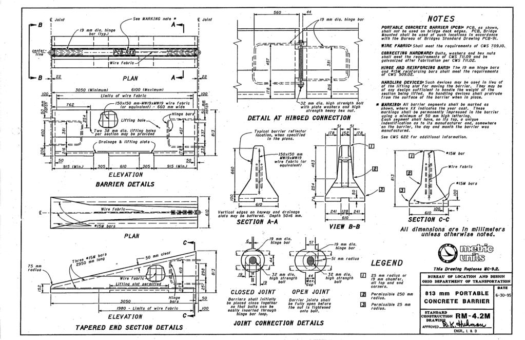
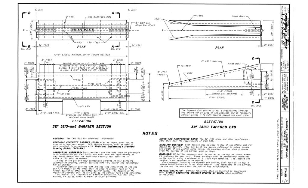
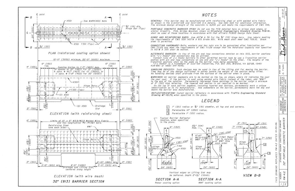
12 B B Joint Joint See MARKINGS Note PCB-RXX-350-TL3 " Y301 (Typ.) " A PLAN (reinforced casting option shown) A " dia. Hinge Bar (Typ.) NOTES GENERAL: This barrier may be manufactured with reinforcing steel or with welded wire fabric as shown in the ELEVATION and SECTION A-A details. See CMS 622 for additional information. The minimum design strength of the concrete is 4,000 psi and meets the requirements of CMS 499. Sections of barrier with the pin and loop connection on one end and the hook plate connection on the other end are permitted, but must be manufactured using the reinforcing steel only. PORTABLE CONCRETE BARRIER BARRIER (PCB): (PCB): Do not use the PCB detailed here on bridge deck edges, or similar drop-offs. PCB, Bridge Mounted, shown on Structural Engineering s Standard Drawing PCB-91. PCB-91, or approved alternative products as shown on the Office of Roadway Engineering s website, shall be used at those locations in accordance with that office s PCBDD Design Data Sheet. HINGE AND REINFORCING BARS: BARS: Use ASTM A 36 for the " hinge bars. Use rebars meeting the requirements of CMS 509 (ASTM A 615 Grade 60). Wire mesh shall meet CMS Black Steel is permitted. CONNECTING HARDWARE: Bolts, washers and hex nuts are to be galvanized after fabrication per CMS and meet the requirements of CMS except that the Rotational Capacity test specified in ASTM A 325 shall be waived. STATE OF OHIO DEPARTMENT OF TRANSPORTATION DATE ADMINISTRATOR 10-0" minimum, 20-0" maximum Typ. Typ. ALTERNATE BARRIER: Approved Alternate Portable Barrier can be found on the Office of Roadway Engineering s Website. HANDLING DEVICES: DEVICES: Such devices may be used in lieu of the lifting slot for moving the barrier. They may be of any design sufficient to safely handle the weight of the section being lifted. No handling devices shall protrude from the surface of the barrier when in place. STDS. ENGINEER M. Ruppe 4" Spacing Varies to 1-7" max. (4 spaces at 19" for 10, 6 spaces at 16.7" for 12, or 11 spaces at 17.8" for 20 ) Y301 (Typ.) 4" notch MARKINGS: All barrier segments are to be marked on the top, as shown, where XX indicates the year cast. If the barrier is cast using welded wire fabric instead of the rebar, add "WWF" to the end of the notation. Permanently impress these markings in the barrier using a minimum of high lettering. The tapered end section is not required to be marked. On the top of each barrier segment, including tapered end sections, permanently mark a unique identification as to its manufacturer. And somewhere on the barrier, permanently mark the day and month the barrier was manufactured. O FFICE O F RO A D W A Y ENGINEERING REFLECTORIZATION: Install barrier reflectors in accordance with Traffic Engineering Standard Drawing 15 " 15" Hinge Bars 18" 13 " MT , when specified in the plans. PAYMENT: This barrier is paid for in feet as ITEM Portable Barrier,. Approved alternatives 8 " 15 " 8 " 4" 8 " 15" 8 " (2) ELEVATION (with reinforcing steel) Reinforcing Steel (one each side) (2) Limits of x W2.9/W2.9 Welded Wire Fabric and two longitudinal #4 bars. 4-0" Drainage and Lifting Slot, 3-0" min. Centered along length Drainage WWF Hinge Bars Slot ELEVATION (with wire mesh) BARRIER SECTION WITH PIN & LOOP CONNECTION 18" 7" 2-10" min. 3-0" min. 7" 9 " 4" 1 9 " 13 " notch 13 " 11 " 2 " 4 " Hinge Bars to the barrier shown on this drawing (and SCD PCB-91) can be found on the Office of Roadway Engineering s website. Typical Barrier Reflector location, when specified in the plans. SECTION A-A SECTION A-A LEGEND 7" 7" dia. 1 Y301 Rebar casting option Clear W2.9/2.9 Hinge x Bars WWF Vertical edges on Lifting Slot may be battered. Depth " #4 Rebar tied to outside of WWF (One each side) WWF casting option radius or " chamfer, all top and end corners. Permissible 10" radius. Permissible radius. 1 19" 10" 3" 4" VIEW B-B 2 Hinge Bars 3 THIS DRAWING REPLACES RM-4.2 DATED SCD NUMBER STANDARD ROADWAY CONSTRUCTION DRAWING R M-4.2 PO RTA BLE C O NC RETE BA RRIER Pin & Loop C onnection 1 4
13 (2) X502 X502 PLAN Clear Hinge Bars Hinge Bars C The Tapered End section is not a crashworthy terminal and should not be used on the approach end of temporary barrier unless it is fully located beyond the clear zone. X " CLOSED JOINT Barriers shall initially be placed close together so that Bolts can be easily inserted through Hinge Bar loop. " " " 1 " 3 " " dia. Hinge Bar dia. High Strength Bolt STATE OF OHIO DEPARTMENT OF TRANSPORTATION DATE ADMINISTRATOR 3" radius 4-0" Lifting Slot permitted 10-0" ELEVATION 7 " 16 " 11 " 10 " 3 2 4" SECTION C-C 4 " Hinge Bars OPEN JOINT Barrier joints shall be fully open before the Nut is tightened onto Bolt. max. gap " dia. Hinge Bar radius STDS. ENGINEER M. Ruppe O FFICE O F RO A D W A Y ENGINEERING TAPERED END C WITH PIN & LOOP CONNECTION dia. High Strength Bolt Y301 (Typ.) (2) 1 Typ. (2) 2 - Typ. max. gap (Open Joint) 4" " dia. Hinge Bar 7" 18" PIN & LOOP DETAIL AT HINGED CONNECTION 8 " 15" Connecting Pin Assembly: 1 " dia. High Strength Bolt with Plate Washers (2) and High Strength Heavy Hex Nut. Y301 (Typ.) (2) 25 " 151 dia. dia. (2) 5" dia. Y BENDING DIAGRAM 17 " BARRIER SECTION (reinforced) TAPERED END PIN & LOOP JOINT CONNECTION DETAILS REINFORCING BAR LIST Bar Quantity per typ. length Mark Bar Shape Length #5 9-4" Str " Str " Str Y301 #3 5-5" Bent X502 #5 #5 9-4" 9 - Str. Str THIS DRAWING REPLACES RM-4.2 DATED STANDARD ROADWAY CONSTRUCTION DRAWING SCD NUMBER R M-4.2 PO RTA BLE C O NC RETE BA RRIER Pin & Loop C onnection Shown with reinforcing. 2 4
14 10" 1 10" 10" 1 10" E E 3-0" min. PCB-RXX-350-TL3 (2) 4-0" Drainage and Lifting Slot, Centered along length See MARKINGS Note Y301 (Typ.) PLAN (reinforced casting option shown) 5" 5" " minimum, 20-0" maximum (2) Y301 (Typ.) Drainage Slot ELEVATION (with reinforcing steel) Limits of x W2.9/W2.9 Welded Wire Fabric and two longitudinal #4 bars. 6 x 6 W2.9 x W2.9 WWF 1 - wide x 9-4" long ELEVATION (with wire mesh) BARRIER SECTION WITH HOOK PLATE CONNECTION 5" 5" 1 D D 3-0" min. #5 X 2-0" ASTM A-706 Grade 60 Connector Bars Welded to Hook Plate (3 Typ. Each End) (Typ.) #5 X 9-8" ASTM A-706 Grade 60 Connector Bars Welded to Hook Plate On Both Ends Typical Barrier Reflector location, when specified X X " Angle, Welded Hook Plate 3 - #5 ASTM A-706 GRADE 60 BARS Connector Plate in the plans 4 " 13 " 11 " 2 " Clear Y " SECTION D-D SECTION D-D VIEW E-E Rebar casting option HOOK PLATE #5 X 2-0" ASTM A-706 Grade 60 Connector Bars Welded to Hook Plate (3 Typ. Each End) 10 " CONNECTOR PLAN Production and Use of the 1 " Weld on both sides of rebar " x x " Angle HOOK PLATE CONENCTION Temporarily on Hold (Typ. all 3 bars) " 3 - #5 ASTM A-706 GRADE 60 BARS 5" 5" Ea. End WWF casting option CONNECTOR DETAIL 6 x 6 W2.9 x W2.9 WWF 1 - wide x 9-8" long #5 X 9-8" ASTM A-706 Grade 60 Connector Bars Welded to Hook Plate on Both Ends " " 5" HOOK PLATE 19" 10" 3" 1 " ASTM A-36 Connector Plate R " " " 7" Tack Ea. End " ASTM A-36 Connector Plate Ea. End 7" 2 3 THIS DRAWING REPLACES RM-4.2 DATED STDS. STATE OF OHIO DEPARTMENT OF TRANSPORTATION ENGINEER O FFICE O F SCD NUMBER STANDARD ROADWAY CONSTRUCTION DRAWING PO RTA BLE C O NC RETE BA RRIER RO A D W A Y Hook Plate C onnection ENGINEERING M. Ruppe ADMINISTRATOR DATE R M
15 (2) 3" radius (2) (2) X502 #5 X 2-0" ASTM A-706 X502 Grade 60 Connector Bars 1 " dia. Welded to Hook Plate Hook Plate (3 Typ.) The Tapered End section is not a crashworthy terminal and should not be used on the approach end of temporary barrier unless it is fully located beyond the clear zone. PLAN 10-0" Clear 4-0" Lifting Slot permitted ELEVATION TAPERED END WITH HOOK PLATE CONNECTION 2 - max. HOOK PLATE CONNECTION DETAIL Shown with reinforcing F F #5 X 2-0" ASTM A-706 Grade 60 Connector Bars Welded to Hook Plate (3 Typ.) 10" 1 10" Y401 Bars (Typ.) (2) (2) Grade 60 connector bars 3 (3 typ. each end) 1 #5 X 2-0" ASTM A706 welded to hool plate 2 4" 2 " SECTION F-F Production and Use of the 4 " CLOSED JOINT OPEN JOINT Max separation is. Max rotation of 7 or a minimum horizontal curve radius of 100 ft. HOOK PLATE CONENCTION Temporarily on Hold Barriers are not required to be pulled taught to engage the hook plate connection. ISOMETRIC VIEW 7 THIS DRAWING REPLACES RM-4.2 DATED STDS. STATE OF OHIO DEPARTMENT OF TRANSPORTATION ENGINEER O FFICE O F SCD NUMBER STANDARD ROADWAY CONSTRUCTION DRAWING PO RTA BLE C O NC RETE BA RRIER RO A D W A Y Hook Plate C onnection ENGINEERING M. Ruppe ADMINISTRATOR DATE R M
RAIL PANEL AT TRANSITION SECTION PLAN - POST DETAIL PLAN - TUBE SPLICE. Colorado Department of Transportation. Staff Bridge Branch
 Limits of pay length for Bridge RailType 10M (For post spacing, see Dwg. No. B ) B60610 (Use with B60610A) 8 min. 1 max. 8 min. 1 max. 10 0 Max. 10 0 Max. post spacing 10 0 Max. 2 5 Post 1 x 1 slotted
Midwest Roadside Safety Facility
 19'-11 1/2" 6083 239'-11 1/2" 73139 Impact 1100C 25 43 5/16" 1100 upstream from the upstream face of the first shear fender downstream of the joint between barrier nos. 7 and 8 Upstream End Downstream
5/16" Flange nut. Bolt Keeper Plate (8" Sq. SYS.) (3) 1/2" x 3" Hex head connector zinc plated bolt w/ washers and nut. Anchor 3" sq. 7 Ga.
 (3) 1/2 x 3 Hex head connector zinc plated bolt w/ washers and nut. Anchor 3 sq. 7 Ga.") 2 1/2" x 2 1/2" x 10 Ga. 6" 5" 4" Variable Slipbase (8" Sq. SYS.) 5/16 Corner Bolt W/ nut 5/16" Flange nut Stub Insert (8" Sq. SYS.) Bolt Keeper Plate (8" Sq. SYS.) (3) 1/2" x 3" Hex head connector zinc
2 1/2" x 2 1/2" x 10 Ga. 6" 5" 4" Variable Slipbase (8" Sq. SYS.) 5/16 Corner Bolt W/ nut 5/16" Flange nut Stub Insert (8" Sq. SYS.) Bolt Keeper Plate (8" Sq. SYS.) (3) 1/2" x 3" Hex head connector zinc
ALUMINUM PIPE GUIDERAIL 01/01/
 NOTES PIPE RAILING & POSTS: Structural Tube, Pipe and Bar shall be in accordance with ASTM B22 or ASTM B429, Alloy 606-T6. End Rail 90 bends and corner bends with maximum 4-0" post spacing, may be Alloy
STEEL PIPE GUIDERAIL 01/01/
 NOTES PIPE RAILING & POSTS: Pipe Rails and s shall be in accordance with ASTM A5 Grade B for standard weight pipe and ASTM A500 Grade B, C or D or ASTM A50 for structural tube. Bars for handrail supports
Installation Instructions
 Column & Beam Units with Debris Netting Installation Instructions Laminated Wood Systems, Inc. Seward, Nebraska 800-949-3526 2015 LWS, INC. AVR-NET INSTALL 05-12-16 AVR Installation Notes 1 Safety The
(50 FT FT) MICHIGAN DEPARTMENT OF TRANSPORTATION 10-0" 7-6" 8-0" 6-0" Truss Depth. 3" sheets 5 & 6 of 10) DEPARTMENT DIRECTOR. Kirk T.
 MICHIGAN DEPARTMENT OF TRANSPORTATION 10-0 7-6 8-0 6-0 Truss Depth. 3 sheets 5 & 6 of 10) DEPARTMENT DIRECTOR. Kirk T.") Column truss connection (See details sheets 3 & 4 of 10) \ Span (Odd number of panels) \ Span (Even number of panels) Back truss chord Top truss chord \ Truss Chord splice Truss depth (See details \ Left
Column truss connection (See details sheets 3 & 4 of 10) \ Span (Odd number of panels) \ Span (Even number of panels) Back truss chord Top truss chord \ Truss Chord splice Truss depth (See details \ Left
Midwest Roadside Safety Facility
 C 1690" A 42926 75" 1905 150" 3810 G E F F 11 10 9 8 7 6 5 4 3 2 C D D 25 18 17 16 15 14 13 12 11 10 9 8 7 6 5 4 3 2 1 21.2 G E Impact 2270P 17 Spaces @ 75" [1905] Spacing = 106' 3" [32385] 1 1662 1/2"
TYPE J (20 FT - 40 FT) MICHIGAN DEPARTMENT OF TRANSPORTATION 10-0" 7-6" NOTE: sheet 5 & 6 of 10) DEPARTMENT DIRECTOR. Kirk T.
 MICHIGAN DEPARTMENT OF TRANSPORTATION 10-0 7-6 NOTE: sheet 5 & 6 of 10) DEPARTMENT DIRECTOR. Kirk T.") Column truss connection Chord splice (see details (See details sheets 3 & 4 of 10) s Top truss chord Free end panel 10-0" Support end panels length varies (See chart below) \ Truss Back truss chord Top
Column truss connection Chord splice (see details (See details sheets 3 & 4 of 10) s Top truss chord Free end panel 10-0" Support end panels length varies (See chart below) \ Truss Back truss chord Top
OHIO DEPARTMENT OF TRANSPORTATION CENTRAL OFFICE, 1980 W. BROAD ST., COLUMBUS, OHIO
 OHIO DEPARTMENT OF TRANSPORTATION CENTRAL OFFICE, 1980 W. BROAD ST., COLUMBUS, OHIO 43216-0899 July 20, 2012 To: Users of the Standard Bridge Drawings From: Tim Keller, Administrator, Office of Structural
HEADED ANCHOR BOLT OPTION
 Ground Rod 18" min. Depth, 2 Required nchor Bolts. Number (min. 8) and Size as Required by Manufacturer. 6" to 12" Ground Line " dia. Conduit Number and Direction as Shown on Lighting Layout Sheets. Slope
Midwest Roadside Safety Facility
 B 64" 1626 602'-8 1/16" 183695 548'-0" 167030 1 2 3 4 5 6 7 8 9 10 11 12 14 15 16 17 18 20 21 22 23 24 25 26 27 28 29 30 31 32 33 34 35 36 373839 40 25 IMPACT 1500A 48" 12 27'-5" 8355 [] 3x7 CL A Galvanized
Midwest Roadside Safety Facility
 28 Spaces @ 75"=2100" 100' 3:1 Cut 40' 75" (TYP.) 3:1 Soil Cut 3:1 1 2 3 4 5 6 7 8 9 10 25 12 13 11 14 15 16 17 18 19 20 21 22 23 24 25 26 75" 300" or Two 12'-6" Section End Section 300" or Two 12'-6"
Midwest Roadside Safety Facility
 28 Spaces @ 75"=175'-0" 100'-0" 3:1 Cut 40'-0" 6'-3" (TYP.) 3:1 Soil Cut 3:1 1 2 3 4 5 6 7 8 9 10 25 12 13 11 14 15 16 17 18 19 20 21 22 23 24 25 26 6'-3" 25'-0" or Two Section 12-gauge End Section 25'-0"
Midwest Roadside Safety Facility
 28 Spaces @ 75"=175'-0" 6'-3" (TYP.) 8'-0" Soil Cut 1 2 3 4 5 6 7 8 9 10 12 13 11 14 15 16 17 18 19 20 21 22 23 24 25 25 C.I.P. 26 6'-3" 25'-0" or Two Section End Section 25'-0" or Two Section End Section
BRIDGE RAILING, 4 TUBE B-26-F POST DETAILS MICHIGAN DEPARTMENT OF TRANSPORTATION
 \ ƒ" x 1 " SLOTTED HOLE IN POST AND \ ƒ"! HOLE IN RAIL \ "! x 6" SLOTTED ROUND HEAD BOLTS, WITH 1 PLATE WASHER, 1 LOCK WASHER AND HEX. NUT \ ƒ" x 1 " SLOTTED HOLE IN POST AND \ ƒ"! HOLE IN RAIL \ "! x
STEEL ANCHOR BASES ALUMINUM ANCHOR BASES
 max. (Alum.) 20" max. (teel) (ee Note 9) Concrete Foundation Plate 8" x (Typ.) AT-A AT-C Bolt Circle ON TRANFORMER BAE BOTTOM OF BAE (ee Note 8) CONNECTOR 1" 1 " pecial Flat asher Š" - " Tapped Hole for
SURVEYOR SURVEYOR + ODOT DESIGN 1 DESIGN 2 RESE T DESIGN 3 DESIGN 4 C/L X MON. CAP DESIGN NAME NAME or COMPANY ODOT o rlpa R/W PS or ODOT o rlpa R/W P
 SURVEYOR SURVEYOR + ODOT DESIGN 1 DESIGN 2 RESE T DESIGN 3 DESIGN 4 C/L X MON. CAP DESIGN or COMPANY ODOT o rlpa R/W or ODOT o rlpa R/W NO.00000 NO.00000 or COMPANY NO.00 000 and/or COMPAN Y SURVEYOR SURVEYOR
E:\Wilmot\DGN\14018pp.dgn 3/11/2015 6:49:16 AM
 600-06 SHOULDER WIDENING FOR TYPE (SPECIAL) GUARDRAIL TERMINALS E:\Wilmot\DGN\08pp.dgn //05 6:9:6 AM E:\DGN\08SUP.dgn //05 ::55 PM E:\DGN\08SUP.dgn //05 :8:0 PM E:\DGN\08-WRG.dgn //05 :8:5 PM E:\DGN\08SM.dgn
GENERAL ISOMETRIC LAYOUT
 EXISTING OR PROPOSED WIPER WALL SUPPORT STRUCTURE GATE LID CARBATHAN HG 0 WEB GRAY LOWER PAN GRATING ALUMINUM WIPER WALL CARBATHANE HG, 90 GRAY STRUCTURAL SPECIFICATIONS:. FLOODGATE MATERIAL TO BE ALUMINUM
Foundation Specifications for 5.6-Meter Modular Earth Station Antennas
 Installation Instructions Bulletin 237029 Foundation Specifications for 5.6-Meter Modular Earth Station Antennas Revision A Introduction This document specifies typical foundation characteristics, designs,
2. Remove from the Standard Plate manual: Standard Plate Index, Sheets 1-4 of 4, Numerical Index of Standard Plates (August 31, 2012)
") MINNESOTA DEPARTMENT OF TRANSPORTATION DEVELOPED BY: Design Standards ISSUED BY: Office of Program Management & Technical Support, Design Support Section TRANSMITTAL LETTER NO. (12-04) MANUAL: Standard
MINNESOTA DEPARTMENT OF TRANSPORTATION DEVELOPED BY: Design Standards ISSUED BY: Office of Program Management & Technical Support, Design Support Section TRANSMITTAL LETTER NO. (12-04) MANUAL: Standard
10x12 FOUNDATION GUIDE 10x12 TRICO AND FLORA SHEDS
 10x12 FOUNDATION GUIDE 10x12 TRICO AND FLORA SHEDS 10x12 WOOD SKID FLOOR FLOOR SYSTEM FOR 10x12 TRICO AND FLORA SHEDS RAW MATERIALS LIST: 2 (9) FLOOR FRAMING AND SHEATHING: 1) BAND BOARD 2 x 6 x 12 PRESSURE
Foundation Specifications for 7.6-Meter Modular Earth Station Antennas
 Installation Instructions Foundation Specifications for 7.6-Meter Modular Earth Station Antennas Bulletin 237186A Revision A Introduction This document specifies typical foundation characteristics, designs,
SECTION STEEL LIGHTING STANDARDS. 1. Electrical conduit and fittings; Section
 02760-1 of 5 SECTION 02760 STEEL LIGHTING STANDARDS 02760.01 GENERAL A. Description Steel lighting standards shall include, but not necessarily be limited to, furnishing and installing steel lighting poles,
Manhole or Catch Basin Type A & B Cone Sections Precast - Design F Manhole or Catch Basin Cover (Reducer Cone Section Precast) Design D
 Design D") MINNESOTA DEPARTMENT OF TRANSPORTATION DEVELOPED BY: Design Standards ISSUED BY: Office of Program Management and Technical Support, Design Support Section TRANSMITTAL LETTER NO. (14-02) MANUAL: Standard
MINNESOTA DEPARTMENT OF TRANSPORTATION DEVELOPED BY: Design Standards ISSUED BY: Office of Program Management and Technical Support, Design Support Section TRANSMITTAL LETTER NO. (14-02) MANUAL: Standard
SUBJECT: Standard Plates 4132, 4155, Drainage Structures and Castings Info
 MINNESOTA DEPARTMENT OF TRANSPORTATION DEVELOPED BY: Design Standards ISSUED BY: Office of Project Management and Technical Support, Design Support Section TRANSMITTAL LETTER NO. (18-01) MANUAL: Standard
WAL-MART SUPERCENTER # ; Milwaukie, OR: SPECIFICATIONS. Revisions to Specification Fence
 MILWAUKIE OR #3144-00 ADDENDUM #5 NARRATIVE: 11-08-12 WAL-MART SUPERCENTER #3144-00; Milwaukie, OR: SPECIFICATIONS SPECIFICATIONS Revisions to Specification 02822 Fence Spec division 02822 has been revised
Installation Instructions
 Installation Instructions SRT-350 8 POST Guardrail End Treatment Revised July 2005 TRINITY HIGHWAY SAFETY PRODUCTS, INC. BUILDING TOMORROW S HIGHWAY SAFETY SOLUTIONS TODAY 2 SRT TM 8-POST SYSTEM FOR SPECIFIC
Utility Structures. Utility vaults, trenches, transformer pads Electrical Pole Bases and switching cubicles
 Utility Structures Utility vaults, trenches, transformer pads Electrical Pole Bases and switching cubicles PRODUCT GUIDE & TECHNICAL REFERENCE MANUAL Providing the right solutions. UTILITY STRUCTURES Perfect
SKT-SP Tangent Terminal
 Assembly Instructions for metric SKT-SP Tangent Terminal & FLEAT-SP Flared Terminal SP Standard Post System Guardrail Terminals ROAD SYSTEMS, INC. P. O. Box 2163 Big Spring, Texas 79721 Phone: (432) 263-2435
SECTION 58 PRECAST CONCRETE BOX CULVERT. This work consists of furnishing and installing Pre-cast Concrete Box Culverts.
 SECTION 58 PRECAST CONCRETE BOX CULVERT 58.1 DESCRIPTION A. General This work consists of furnishing and installing Pre-cast Concrete Box Culverts. B. Related Work Section 51 Section 52 Section 53 Section
Midwest Roadside Safety Facility
 2 Spaces @ 75" [05]= 150" 3810 4 Spaces @ 3 Spaces @ 4 Spaces @ 18.75" 37.5" [953]= 37.5" [953]= [476] 112 1/2" 150" = 75" 2857 3810 [05] 18 476 7 Spaces @ 75" [05]=525" [13335] 21 20 18 17 1615 14 1312
CHAPTER 10 MICHIGAN DESIGN MANUAL BRIDGE DESIGN (SI) SHOP DRAWING REVIEW TYPES OF SHOP DRAWINGS Structural Steel
 SHOP DRAWING REVIEW TYPES OF SHOP DRAWINGS Structural Steel") CHAPTER 10 SHOP DRAWING REVIEW 10.01 TYPES OF SHOP DRAWINGS 10.01.01 Structural Steel 10.01.02 Prestressed Concrete 10.01.03 Bearings 10.01.04 Metal Stay - In - Place Forms () 10.01.05 Expansion Joints
CHAPTER 10 SHOP DRAWING REVIEW 10.01 TYPES OF SHOP DRAWINGS 10.01.01 Structural Steel 10.01.02 Prestressed Concrete 10.01.03 Bearings 10.01.04 Metal Stay - In - Place Forms () 10.01.05 Expansion Joints
Current Standard Plates including Transmittal Letters are available on the web at:
 MINNESOTA DEPARTMENT OF TRANSPORTATION DEVELOPED BY: Design Standards ISSUED BY: Office of Project Management and Technical Support, Design Support Section TRANSMITTAL LETTER NO. (17-04) MANUAL: Standard
Current Standard Plates including Transmittal Letters are available on the web at:
 MINNESOTA DEPARTMENT OF TRANSPORTATION DEVELOPED BY: Design Standards ISSUED BY: Office of Project Management and Technical Support, Design Support Section TRANSMITTAL LETTER NO. (15-03) MANUAL: Standard
ADA-COMPLIANT SAFETY DEVICES PRODUCT GUIDE. SafetyRail TM Barricade SafetyWall TM Barricade BoardWalk Temporary RAMP
 ADA-COMPLIANT SAFETY DEVICES PRODUCT GUIDE SafetyRail TM Barricade SafetyWall TM Barricade BoardWalk Temporary RAMP SafetyWall TM ADA-COMPLIANT PEDESTRIAN BARRICADE Ideal for creating accessible work zones.
Big expertise. Real convenience. Concrete commitment. stem
 1300 659 830 www.formdirect.com.au Big expertise. Real convenience. Concrete commitment. Stee l Pre-e P n g i n eere ly Fo conc d rete form, factory rmin ing s ystem built, re-u g sy sable stem Steel-Ply
BoardWalk RAMP: Installation and Assembly Instructions
 BoardWalk RAMP: Installation and Assembly Instructions The BoardWalk RAMP Platform and Handrail System will accommodate curbs 3" - 12" high. Adhering to ADA guidelines of 1:12 rise ratio: The system shown
B-27-A BRIDGE RAILING, 3 TUBE WITH PICKETS SECTION THROUGH RAILING WITH BRUSH BLOCK SECTION THROUGH RAILING WITH SIDEWALK
 3" 1'- ƒ " 11 " 7 " TOP OF REAR FLANE TO BE ROUND 2'- LON PICKET 1'- W6 x 25 1 " THICK BASE PLATE " " ELASTOMERIC BOUND FABRIC PAD 8" SLAB DETAIL A (SEE 3) OVERHAN SECTION THROUH RAILIN WITH BRUSH BLOCK
S48-L12-SC AND G48-L12-GC STEEL PORTA-DOCK S82 SC 6 X 12 PLATFORM AND G82 GC 6 X 12 PLATFORM
 PAGE 1 OF 6 PORTA-DOCK, INC. S48-L12-SC AND G48-L12-GC STEEL PORTA-DOCK S82 SC 6 X 12 PLATFORM AND G82 GC 6 X 12 PLATFORM Thank you for purchasing our product! *Please read these instructions and follow
FOR PROFESSIONAL GARAGE DOOR INSTALLERS
 Composite Garage Doors Installation Instructions FOR PROFESSIONAL GARAGE DOOR INSTALLERS Tools required Screwdriver Claw Hammer Locking Pliers Power Drill Level with a 3/32" Drill Bit Utility Knife 9/16",
Open shipping crate and separate all of the different parts. Over The Top Shelters LLC
 ASSEMBLY INSTRUCTIONS FOR MODEL SH122110GN and SH122110GY Open shipping crate and separate all of the different parts. Count each part and match up with parts list. Shortages or damaged parts should be
MH Table of Contents Standard Title/Scope Page Table of Contents SCE Public
 MH Table of Contents Standard Title/Scope MH 300 MH 310 MH 318 MH 320 MH 325 MH 330 MH 335 MH 340 MH 350 Manholes Requirements MH 300.1 Manholes Requirements...........................................
24 X32 3 CAR GARAGE POLE BARN STYLE FRAME
 24 X32 3 CAR GARAGE POLE BARN STYLE FRAME 3 ENTRY DOOR 2 WINDOWS, 1 @ EA. END 1-16 X8 GARAGE DOOR 1-9 X8 GARAGE DOOR 4 CONCRETE SLAB 10 WALLS 4/12 PITCH METAL ROOF METAL SIDING INDEX PAGE DESCRIPTION 1
M2 Antenna Systems, Inc. Model No: YAGI ANTENNA
 M Antenna Systems, Inc. Model No: 4.5-7 YAGI ANTENNA SPECIFICATIONS: Model... 4.5-7 Frequency Range... 4.0 To 4.5 MHz *Gain... 0 To 7 dbi Front to back... 0 db over the rear 80 Beamwidth... E=44 H=50 typical
INSTALLATION TORSION SPRING FRONT OR REAR MOUNT LOW HEADROOM. 1 Cutting Vertical Track. 2 Fully Adjustable Jamb Brackets
 TORSION SPRING FRONT OR REAR MOUNT LOW HEADROOM Wayne Dalton, a division of Overhead Door Corporation P.O. Box 67, Mt. Hope, OH., 44660 Supplemental insert Copyright 2015 Wayne Dalton, a division of Part
Manholes Table of Contents
 Standard MH 300 Title Manholes Requirements MH 300.1 Manholes Requirements Manholes Table of Contents Underground Structures Standards MH 310 MH 318 MH 320 MH 325 MH 330 MH 335 MH 340 MH 350 Precast Tub-Type
DISTRIBUTION VAULT 8' x 14' x 9'-4" DEEP TRAFFIC FLAT WALL WITH 5' x 8' OPENING
 CU16003K REV 8' x 14' x 9'4" DEEP TRAFFIC FLAT WALL 0113 SHEET 1 OF 6 CU 16003K CU16003K REV 8' x 14' x 9'4" DEEP TRAFFIC FLAT WALL 0113 SHEET OF 6 CU 16003K ITEM (PER ENDWALL): A. 6" DIAMETER PVC CONDUIT
Standard Plate Sheer Reinforcement for Precast Drainage Structures has been updated upon recommendation of the Bridge Office.
 MINNESOTA DEPARTMENT OF TRANSPORTATION DEVELOPED BY: Design Standards ISSUED BY: Office of Program Management and Technical Support, Design Support Section TRANSMITTAL LETTER NO. (13-03) MANUAL: Standard
Installation and Assembly: Flat Video Wall Mount For 40" to 65" Flat Panel Displays
 Installation and Assembly: Flat Video Wall Mount For 40" to 65" Flat Panel Displays Model: DS-VW665 Maximum Load Capacity: 125 lb (57 kg) 1 of 11 ISSUED: 03-22-12 SHEET #: 125-9288-4 06-25-13 NOTE: Read
END VIEW WEDGE TOP VIEW WOOD POST FOUNDATION DETAILS
 X (NOMINAL POST) 1-1/ DIA. 2 HOLES X 8" (NOMINAL POST) 3-1/ DIA. 2 HOLES TAPERED HARD WOOD WEDGES (HARDWOOD WEDGE TO BE OAK, MAPLE OR OTHER APPROVED DENSE HARDWOODS) TO HOLD POST IN A STABLE POSITION AFTER
Installation Instructions - Model V4JSD 1
 Installation Instructions - Model V4JSD 1 Support Assemblies: Parts list: (Note see enclosed cut sheet for quantities and dimensional information) A vertical structural member (1 ½ x 1 ½ modular frame)
Shearwall System Installation Guide
 Shearwall System Installation Guide Complete HFX product listing with dimensions, weights, connectors, typical installations and accessories. Also includes Hardy Frame Moment Frame information. Easy as
SUBJECT: Standard Plate Turf Establishment Areas (at Pipe Culvert Ends)
") MINNESOTA DEPARTMENT OF TRANSPORTATION DEVELOPED BY: Design Standards ISSUED BY: Office of Program Management and Technical Support, Design Support Section TRANSMITTAL LETTER NO. (14-01) MANUAL: Standard
MINNESOTA DEPARTMENT OF TRANSPORTATION DEVELOPED BY: Design Standards ISSUED BY: Office of Program Management and Technical Support, Design Support Section TRANSMITTAL LETTER NO. (14-01) MANUAL: Standard
B " 787
 175'0" 53339 3H:1V S.B.P. 25" 635 3H:1V Slope 100'0" 30480 Soil Cut 3H:1V Slope 58" 1474 75" 05 1 2 3 4 5 6 7 8 9 10 11 12 13 25 14 15 16 17 18 20 21 22 23 24 25 2270P Impact 243 60 12 Spaces @ 75" [05]
SIGNALS AND LIGHTING FIELD GUIDE
 CHAPTER 16 SIGNAL AND LIGHT POLES SIGNAL AND LIGHT POLES The standards and requirements for installing traffic control signal and light poles are presented in this chapter. 16.1 Traffic Control Signal
APPENDIX FENCE GENERAL NOTES
 APPENDIX FENCE GENERAL NOTES 1. Fabric: 9 gage, 2" mesh, knuckle top and bottom, placed on the outside of posts, single fabric width for the entire height. 2. All fencing to be standard galvanized finish.
Kwik-Lock. Installation Instructions. Attention Dealers: Please give this owners manual to the customer when the product is delivered.
 Serving the Truck & Trailer Industry Since 1944 Installation Instructions Attention Dealers: Please give this owners manual to the customer when the product is delivered. Call 800-535-9545 www.aeroindustries.com
AUXILIARY FRAMING AND ACCESSORIES
 CUSTOM CABINETS & RACKS STRUT AND ACCESSO- RIES JUNCTION KITS ANGLE AND BRACE KITS SPLICE KITS BRACE KITS INSTALLATION KITS WALL ANGLE KITS RUBBER END CAPS SUPPORT INSTALLATION AND SUPPORT KITS STANCHION
DOCK WEDGE - STANDARD
 DOCK WEDGE - STANDARD INSTALLATION INSTRUCTIONS WOOD HEADER READ ALL INSTRUCTIONS BEFORE INSTALLING SEAL. SUPER SEAL MFG. LTD. WILL NOT BE HELD RESPONSIBLE FOR IMPROPER INSTALLATION OF ANCHORING DEVICES,
TECHNICAL CORRECTION October Process Industry Practices Structural. PIP STF05121 Fabrication and Installation of Anchor Bolts
 TECHNICAL CORRECTION October 2006 Process Industry Practices Structural PIP STF05121 Fabrication and Installation of Anchor Bolts PURPOSE AND USE OF PROCESS INDUSTRY PRACTICES In an effort to minimize
M4 Hex Nut [ ] M4 T-Nut 20 [20-044] Appx. 1. 3mm. 20 Series profiles (1 per hole) (1 per hole) Ordering Information
![M4 Hex Nut [ ] M4 T-Nut 20 [20-044] Appx. 1. 3mm. 20 Series profiles (1 per hole) (1 per hole) Ordering Information](/thumbs/77/74547895.jpg "M4 Hex Nut [ ] M4 T-Nut 20 [20-044] Appx. 1. 3mm. 20 Series profiles (1 per hole) (1 per hole) Ordering Information") Handles & Light Duty PA 20 1 Assembly of Hinge M4x8 FHCS [24-208-4] M4 T-Nut 20 [20-044] M4 Hex Nut [24-706-4] 60 300-0 PA 20 on panel 2 Hinge positions 3-4 Clearance dimensions 5 Range of swing FOR M4
Handles & Light Duty PA 20 1 Assembly of Hinge M4x8 FHCS [24-208-4] M4 T-Nut 20 [20-044] M4 Hex Nut [24-706-4] 60 300-0 PA 20 on panel 2 Hinge positions 3-4 Clearance dimensions 5 Range of swing FOR M4
COMPACT DECK. Compact Deck SOUTHERN FOREST PRODUCTS ASSOCIATION SOUTHEASTERN LUMBER MANUFACTURERS ASSOCIATION
 COMPACT DECK SOUTHERN FOREST PRODUCTS ASSOCIATION SOUTHEASTERN LUMBER MANUFACTURERS ASSOCIATION P.O. BOX 641700 KENNER, LA 70064-1700 (504) 443-4464 FAX (504) 443-6612 www.southernpine.com Compact Deck
TYPE 4-C TYPE 6 TYPE 7 TYPE 8
 ````` Face of ase rad. 42 TYPE rad. " T T T 22.5 2'- unless otherwise shown on plans 5" 5" 5" Slope 2: TYPE 2 rad. Concrete TYPE 2-A rad. Wearing Course Concrete ase Course TYPE 2-0" rad. TYPE 3 As Shown
Installation and Assembly: Full Service Video Wall Mount
 Installation and Assembly: Full Service Video Wall Mount Model: DS-VW765-LAND Max UL Load Capacity: 125 lb (57 kg) 1 of 12 ISSUED: 05-13-11 SHEET #: 145-9011-5 05-21-12 Note: Read entire instruction sheet
Thread protection accessories are installed at the MODIX production factory and delivered with couplers.
 Installation of MODIX Rebar Coupler Identification of the product The type of MODIX Rebar Coupler can be identified by the marking on the product. Size of the Coupler can be identified also according to
INSTALLATION INSTRUCTIONS FOR SL-LB MANUAL LIFT BARRIER GATE ARMS
 INSTALLATION INSTRUCTIONS FOR SL-LB MANUAL LIFT BARRIER GATE ARMS Questions? Call 520-780-9751 or visit our website at: www.barriergatearm.com YOUR SL-LB MANUAL LIFT BARRIER GATE ARM WILL ARRIVE WITH WEIGHT
OPERATOR'S MANUAL 46" SNOW BLADE. Model Numbers OEM IMPORTANT: READ SAFETY RULES AND INSTRUCTIONS CAREFULLY
 OPERATOR'S MANUAL 46" SNOW BLADE Model Numbers 190-833-OEM IMPORTANT: READ SAFETY RULES AND INSTRUCTIONS CAREFULLY MTD PRODUCTS INC. P.O. BOX 368022 CLEVELAND, OHIO 44136-9722 PRINTED IN U.S.A. FORM NO.
METAL BENDER OPERATING & MAINTENANCE INSTRUCTIONS Model Nos: CCB1 & CCB2 Part Nos: & CCB2 CCB1
 METAL BENDER Model Nos: CCB1 & CCB2 Part Nos: 7630073 & 7630074 CCB2 CCB1 OPERATING & MAINTENANCE INSTRUCTIONS 1206 1 The Compact Bender allows you to economically make a variety of bends in flat, square,
SECTION CONCRETE REINFORCEMENT FOR STEAM UTILITY DISTRIBUTION
 PAGE 032015-1 SECTION 032015 PART 1 - GENERAL 1.1 RELATED DOCUMENTS A. Drawings and general provisions of the Contract, including General and Supplementary Conditions and Division 01 Specification sections,
SB-WM-ART2-L-BL SB-WM-ART2-XL-BL
 SB-WM-ART2-L-BL SB-WM-ART2-XL-BL Weatherproof Universal Dual-Arm Articulating Mount for Large TVs INSTALLATION MANUAL WARNING The maximum weight of this wall mount is 150 lbs (68.04 kg). Use with heavier
SUBJECT: Standard Plate 9102 Turf Establishment Areas At Pipe Culvert Ends
 MINNESOTA DEPARTMENT OF TRANSPORTATION DEVELOPED BY: Design Standards ISSUED BY: Office of Project Management and Technical Support, Design Support Section TRANSMITTAL LETTER NO. (17-03) MANUAL: Standard
INSTRUCTIONS: 1. Record the transmittal letter number, date, and subject on the transmittal record sheet located in the front of the manual.
 MINNESOTA DEPARTMENT OF TRANSPORTATION DEVELOPED BY: Design Standards ISSUED BY: Office of Technical Support Design Services Section TRANSMITTAL LETTER NO. (0-03) MANUAL: Standard Plates DATED: September
STRATUS SHELTER. Take bike parking to new heights
 Take bike parking to new heights The Stratus Shelter is a striking bike shelter option for any transit station, university campus, or multi-family residential building project. It is constructed of American
MAST ARMS & POLES. Ornamental Pole Top & Bases
 Ornamental Pole Top & Bases Pelco s decorative pole top and bases make the traffic signal aesthetically pleasing to the eye. In addition to the standar 4-piece, Pelco also manufactures the bases with an
SIG-032-B TRAFFIC SIGNAL MAST ARM POLE AND MAST ARM DETAILS - CATEGORY III LUMINAIRE ARM (SEE CONTRACT) 6'-0", 8'-0", 10'-0" NOMINAL SPREAD
 6'-0, 8'-0, 10'-0 NOMINAL SPREAD") Michigan Department of Transportation 6'-0", 8'-0", 10'-0" NOMINAL SPREAD (SEE CONTRACT) LUMINAIRE ARM (SEE CONTRACT) POLE CAP 1'-6" (6'-0" ARM) 1'-10" (8'-0" ARM) 2'-0" (10'-0" ARM) NOMINAL RISE 2.38"
Michigan Department of Transportation 6'-0", 8'-0", 10'-0" NOMINAL SPREAD (SEE CONTRACT) LUMINAIRE ARM (SEE CONTRACT) POLE CAP 1'-6" (6'-0" ARM) 1'-10" (8'-0" ARM) 2'-0" (10'-0" ARM) NOMINAL RISE 2.38"
Pipe Product Catalog Table of Contents
 Pipe Product Catalog Table of Contents Section A: Drawing #: Page Description A1 Reinforced Concrete Pipe A3 Storm Manhole Sizing Chart (48" - 96") A3.1 Storm Manhole Sizing Chart (108" - 144") A4 48"
SECTION STRUCTURAL STEEL FRAMING PART 1 - GENERAL 1.1 RELATED DOCUMENTS
 SECTION 05 12 00 - STRUCTURAL STEEL FRAMING PART 1 - GENERAL 1.1 RELATED DOCUMENTS A. Drawings and general provisions of the Contract, including General and Supplementary Conditions and Division 01 Specification
INSTALLATION GUIDE PermaTrak. Patented Product: U.S. Patent #5,906,084 #8,302,362 #8,522,505 #8,839,588 #9,096,975
 INSTALLATION GUIDE 2009-2017 PermaTrak. Patented Product: U.S. Patent #5,906,084 #8,302,362 #8,522,505 #8,839,588 #9,096,975 Table of Contents Project Overview Forward, Acceptability Criteria, Safety,
C. Samples for Initial Selection: Manufacturer's color charts showing the full range of colors available.
 SECTION 105113 - METAL LOCKERS PART 1 - GENERAL 1.1 RELATED DOCUMENTS A. Drawings and general provisions of the Contract, including General and Supplementary Conditions and Division 01 Specification Sections,
Tunnel Door Installation & Operator s Instruction Manual
 Tunnel Door Installation & Operator s Instruction Manual March 006 MV89A Chore-Time Warranty Tunnel Door Chore-Time Warranty Chore-Time Equipment ( Chore-Time ) warrants each new Chore-Time product manufactured
SPECIFICATIONS FOR THE MANUFACTURE AND DESIGN OF PRECAST THREE SIDED ARCH STRUCTURES, WINGWALLS AND HEADWALLS
 SPECIFICATIONS FOR THE MANUFACTURE AND DESIGN OF PRECAST THREE SIDED ARCH STRUCTURES, WINGWALLS AND HEADWALLS 1. DESCRIPTION THESE SPECIFICATIONS ARE FOR A PRECAST THREE SIDED ARCH STRUCTURE, HEADWALLS
Qwik-Fence Installation Instructions
 Qwik-Fence Installation Instructions 1 Tools Required The following installation instructions should be used as a guide for installing Folding Guard Qwik-Fence Partitions. Good common sense and appropriate
Procedure for Testing Direct Tension Indicators (DTI) Assemblies
 Assemblies") Procedure for Testing Direct Tension Indicators (DTI) Assemblies 1. Scope: This test is to ensure that the bolt will be at or above the specified minimum bolt tension after installation when the direct
Procedure for Testing Direct Tension Indicators (DTI) Assemblies 1. Scope: This test is to ensure that the bolt will be at or above the specified minimum bolt tension after installation when the direct
SIG-030-B TRAFFIC SIGNAL MAST ARM POLE AND MAST ARM DETAILS - CATEGORY I LUMINAIRE ARM 6'-0", 8'-0", 10'-0" NOMINAL SPREAD (SEE CONTRACT) POLE CAP
 POLE CAP") Michigan Department of Transportation 6'-0", 8'-0", 10'-0" NOMINAL SPREAD (SEE CONTRACT) LUMINAIRE ARM (SEE CONTRACT) POLE CAP 1'-6" (6'-0" ARM) 1'-10" (8'-0" ARM) 2'-0" (10'-0" ARM) NOMINAL RISE 2.38"
Michigan Department of Transportation 6'-0", 8'-0", 10'-0" NOMINAL SPREAD (SEE CONTRACT) LUMINAIRE ARM (SEE CONTRACT) POLE CAP 1'-6" (6'-0" ARM) 1'-10" (8'-0" ARM) 2'-0" (10'-0" ARM) NOMINAL RISE 2.38"
Standard Plate 7036 is discontinued. It is replaced by Standard Plan Pedestrian Curb Ramp Details.
 DEVELOPED BY: Design Standards ISSUED BY: Office of Program Management & Technical Support, Design Support Section TRANSMITTAL LETTER NO. (12-02) MANUAL: Standard Plates DATED: May 11, 2012 SUBJECT: Standard
ASSEMBLY INSTRUCTIONS FOR MAR-K BEDSIDES AND GM FLUSH TAILGATE WITH HANDLE
 ASSEMBLY INSTRUCTIONS FOR MAR-K BEDSIDES AND 41-53 GM FLUSH TAILGATE WITH HANDLE Build the box assembly according to the MAR-K assembly instructions. When installing the tailgate and latching mechanisms
Oxford Stalls Installation Instructions
 Oxford Stalls Installation Instructions RAMM Horse Fencing and Stalls 13150 Airport Hwy. Swanton, OH 43558-9615 1-800-434-8456 Rev. 8/15/17 Before You Start Typical stall sizes are 10 x 10, 12 x 12 or
Hex Head Bolt Set N - Includes lock nut. Used to connect male and female T connectors. Galvanized. 3/4" x 3-1/2". Standard Grade (f) Part #24279
 Part #24279") a Standard Grade (3/16 ) and Commercial Grade(1/4 ) Tie Down Is designed for use with 1-1/2" thick lumber (minimum width 6"). All hardware is mounted with 3/8" carriage bolts. All male and female dock
a Standard Grade (3/16 ) and Commercial Grade(1/4 ) Tie Down Is designed for use with 1-1/2" thick lumber (minimum width 6"). All hardware is mounted with 3/8" carriage bolts. All male and female dock
Calf-Tel Pen System Assembly Instructions
 Calf-Tel Pen System Assembly Instructions (Instructions work for 4, 6, and the 7 Pen Systems) 1 ASSEMBLY OF PEN FRONT AND WALLS START THE ASSEMBLY BY LINING UP THE TWO UNI-DIRECTIONAL ARROWS IN THE TOP,
SB-WM-ART1-M-BL. Weatherproof Universal Single-Arm Articulating Mount for Medium Displays INSTALLATION MANUAL
 SB-WM-ART1-M-BL Weatherproof Universal Single-Arm Articulating Mount for Medium Displays INSTALLATION MANUAL WARNING The maximum weight of this wall mount is 90 lbs (41 kg). Use with heavier than the maximum
Strata. urniture. Adriana Instructions. Parts in the Arm Box: Parts in the Body Box: Watch our assembly videos at
 1A Watch our assembly videos at www.strataf.com/videos Parts in the Arm Box: Arm - Outside View Arm - Inside View 1B Parts in the Body Box: Back Deck x 1 Seat Deck x 1 with the Feet attached Back Panel
Sit Down Table Assembly Instructions
 Sit Down Table Assembly Instructions Parts that come with your sit down table A B C D E F G H I J K L M N Extension leaf Table with cutout for machine Two table legs One table leg with long support One
CONTENTS TOOL LIST U P S I D E I N N O V A T I O N S, L L C RAMP AND STEP SYSTEM ASSEMBLY INSTRUCTIONS. Revised: June 2013
 U P S I D E I N N O V A T I O N S, L L C RAMP AND STEP SYSTEM ASSEMBLY INSTRUCTIONS TOOL LIST Required Tools: - Reciprocating Saw with Metal Cutting Blade - Drill - 7/16 Drill Bit for Metal Drilling -
GlideRite Retractable Cover System For Hot Spot Spas (SE & SLX only)
") List of Contents Quantity Description 12 #10 x 1 ½ Flat Head Phillips Screw (see pg. 2) 2 #10 x ½ Pan Head Phillips Screw (see pg. 2) 8 ¼ x 2 ½ Lag Bolt (see pg. 2) 7 ¼ 20 x 5 / 8 Hex Head Bolt (see pg.
List of Contents Quantity Description 12 #10 x 1 ½ Flat Head Phillips Screw (see pg. 2) 2 #10 x ½ Pan Head Phillips Screw (see pg. 2) 8 ¼ x 2 ½ Lag Bolt (see pg. 2) 7 ¼ 20 x 5 / 8 Hex Head Bolt (see pg.
CertainTeed INSTALLATION GUIDE SIMTEK FENCE PRODUCTS. Fence Installation Guide 3', 4' & 6' High
 CertainTeed INSTALLATION GUIDE SIMTEK FENCE PRODUCTS Fence Installation Guide 3', 4' & 6' High INSTALLATION GUIDE These instructions are designed to assist both professional installers and do-it-yourselfers
Tunnel Door (White) Installation & Operator s Instruction Manual
 Installation & Operator s Instruction Manual") Tunnel Door (White) Installation & Operator s Instruction Manual October 009 MV89C Chore-Time Warranty Tunnel Door (White) Chore-Time Warranty Chore-Time Equipment ( Chore-Time ) warrants each new Chore-Time
Tunnel Door (White) Installation & Operator s Instruction Manual October 009 MV89C Chore-Time Warranty Tunnel Door (White) Chore-Time Warranty Chore-Time Equipment ( Chore-Time ) warrants each new Chore-Time
Eraser Conveyor Belt Cleaning System IWARNING Always obey all applicable safety rules. Be sure all power to the conveyor has been disconnected and con
 INSTALLATION GUIDE LIB-CP-REA-03-01 Rev. 10 Eraser Conveyor Belt Cleaning System ARGONICS Eraser Conveyor Belt Cleaning System IWARNING Always obey all applicable safety rules. Be sure all power to the
INTERIOR INSTALLATION
 6" TWO (2) #6 FASTENERS BY OTHERS, NOT BY HUNTER DOUGLAS, TYP. MAIN TEE PER ASTM C635, BY OTHERS, TYP. 2" HANGER BRACKET ASSEMBLY PRIME BEAM* 2" MAX MAIN TEE T-GRID PER ASTM C635 BY OTHERS SEE DETAIL A.2