Tunnel Door (White) Installation & Operator s Instruction Manual
|
|
|
- Curtis Ward
- 5 years ago
- Views:
Transcription

1 Tunnel Door (White) Installation & Operator s Instruction Manual October 009 MV89C
2 Chore-Time Warranty Tunnel Door (White) Chore-Time Warranty Chore-Time Equipment ( Chore-Time ) warrants each new Chore-Time product manufactured by it to be free from defects in material or workmanship for one year from and after the date of initial installation by or for the original purchaser. If such a defect is found by the Manufacturer to exist within the one-year period, the Manufacturer will, at its option, (a) repair or replace such product free of charge, F.O.B. the factory of manufacture, or (b) refund to the original purchaser the original purchase price, in lieu of such repair or replacement. Labor costs associated with the replacement or repair of the product are not covered by the Manufacturer. Conditions and Limitations. The product must be installed by and operated in accordance with the instructions published by the Manufacturer or Warranty will be void.. Warranty is void if all components of the system are not original equipment supplied by the Manufacturer.. This product must be purchased from and installed by an authorized distributor or certified representative thereof or the Warranty will be void.. Malfunctions or failure resulting from misuse, abuse, negligence, alteration, accident, or lack of proper maintenance shall not be considered defects under the Warranty. 5. This Warranty applies only to systems for the care of poultry and livestock. Other applications in industry or commerce are not covered by this Warranty. The Manufacturer shall not be liable for any Consequential or Special Damage which any purchaser may suffer or claim to suffer as a result of any defect in the product. Consequential or Special Damages as used herein include, but are not limited to, lost or damaged products or goods, costs of transportation, lost sales, lost orders, lost income, increased overhead, labor and incidental costs and operational inefficiencies. THIS WARRANTY CONSTITUTES THE MANUFACTURER S ENTIRE AND SOLE WARRANTY AND THIS MANUFACTURER EXPRESSLY DISCLAIMS ANY AND ALL OTHER WARRANTIES, INCLUDING, BUT NOT LIMITED TO, EXPRESS AND IMPLIED WARRANTIES AS TO MERCHANTABILITY, FITNESS FOR PARTICULAR PURPOSES SOLD AND DESCRIPTION OR QUALITY OF THE PRODUCT FURNISHED HEREUNDER. Chore-Time Distributors are not authorized to modify or extend the terms and conditions of this Warranty in any manner or to offer or grant any other warranties for Chore-Time products in addition to those terms expressly stated above. An officer of CTB, Inc. must authorize any exceptions to this Warranty in writing. The Manufacturer reserves the right to change models and specifications at any time without notice or obligation to improve previous models. Effective: October 009 Chore-Time Equipment A Division of CTB, Inc. P.O. Box 000 Milford, Indiana U.S.A. Phone (9) Fax (877) ctb@ctbinc.com Internet: http// Thank You The employees of Chore-Time Equipment would like to thank your for your recent Chore-Time purchase. If a problem should arise, your Chore-Time distributor can supply the necessary information to help you. MV89C
3 Contents Topic Page User Chore-Time Warranty General Support Information Distributor and Installer Information About This Manual Safety Information Installation Framing Rough Opening Height Rough Opening Width Door Hinge Board Sealing the Rough Opening Door Bottom Seal (Black P-Seal) Attaching Perimeter Seal (White P-Seal) Door Assembly/Installation Bottom C-Channel with Hinges Attaching the Door Assembly Attaching second FRP Panel Installing Flat Washers & Nylon Split Bolt on the st FRP Panel Installing Nylon Rope on st FRP Panel to temporarily hold Door(s) in place Continuing to add FRP Panels and Temporary Tie-ups Installing Flat Washers & Nylon Split Bolt on the Last FRP Panel Installing remaining Nylon Ropes Control Wire Eyehooks Control Wire Installation Attaching Control Wire to Cable (Winch End) Installing Counter Weight (Concrete Block) Installing Counter Weight (Spring) Attaching Nylon Ropes to Control Wire Tighten down Nylon Ropes and Final Adjustments Caulking Itemized Parts (Continuous Doors) Part Numbers (Continuous Doors) Itemized Parts and Part Numbers (Pre-assembled Doors) Optional Parts Listing D,C C C,I C,I I C,I C,I C,I I,D MV89C * Legend: C = Customer (end user), D = Distributor (sales), I = Installer of equipment
4 General Tunnel Door (White) General Support Information The Chore-Time Tunnel Door is to be used to control the airflow in a Tunnel Ventilated poultry house. Using this equipment for any other purpose or in a way not within the operating recommendations specified in this manual will void the warranty and may cause personal injury. This manual is designed to provide comprehensive planning, installation, safety, operation, and parts listing information. The Table of Contents provides a convenient overview of the information in this manual. The Table of Contents also specifies which pages contain information for the sales personnel, installer, and consumer (end user). Distributor and Installer Information Please fill in the following information about your Product. Keep this manual in a clean, dry place for future reference. Distributor s Name Distributor s Address Distributor s Phone Date of Purchase Installer s Name Installer s Address Installer s Phone Date of Installation System Specifications MV89C
5 Tunnel Door (White) About This Manual About This Manual The intent of this manual is to help you in two ways. One is to follow step-by-step in the order of assembly of your product. The other way is for easy reference if you have questions in a particular area. Important! Read ALL instructions carefully before starting construction. Important! Pay particular attention to all SAFETY information. Metric measurements are shown in millimeters and in brackets, unless otherwise specified. " equals inches and ' equals feet in English measurements. Examples: " [5.] ' [ 9] Safety Information Optional equipment contains necessary instructions for assembly or operation. Major changes from the last printing will be listed on the back cover. Very small numbers near an illustration (i.e., 57-8) are identification of the graphic, not a part number. Caution, Warning and Danger Decals have been placed on the equipment to warn of potentially dangerous situations. Care should be taken to keep this information intact and easy to read at all times. Replace missing or damaged safety decals immediately. Using the equipment for purposes other than specified in this manual may cause personal injury and/or damage to the equipment. MV89C 5
. Failure to do so will result in a poorly sealed Tunnel Door.")
6 Installation Tunnel Door (White) Installation Framing It is very important to make sure the Tunnel Door opening is flat. A maximum of /" rise or fall throughout the length of the opening is all that is acceptable (See Figure ). Failure to do so will result in a poorly sealed Tunnel Door. The same rules apply for pre-assembled doors. Rough Opening Height Frame up the rough opening (Item, Figure ) so that the height is " less than the Tunnel Door height. Example: ft (8") Tunnel Door = 7" Rough Opening height; 5 ft (60") Tunnel Door = 59" Rough Opening height Rough Opening Width The Rough Opening width is determined by the length of the Doors. The opening width should be " less than the Tunnel Door Length. Max. /" rise or fall of Tunnel Door opening Max. /" rise or fall of Tunnel Door opening Rough Opening Height (Door Height -") Rough Opening Length (Door Length -") Figure. Framing Framing for Pre-assembled Doors 6 MV89C


. Chalk-Line Straight \" Min. both sides 6\" Approx.")
7 Tunnel Door (White) Installation Door Hinge Board Attach a treated X (Item, Figure ) to the bottom of the Rough Opening using /" Long Deck Grade Wood Screws in a zig-zag pattern, spacing the screws approximately 6" apart as shown in Figure. The Door Hinge Board Must Protrude " Past Both Ends Of The Rough Opening to allow for proper sealing of the Tunnel Door. Note: The Top Of The Door Hinge Board Must Be Chalk Line Straight Horizontally To Ensure A Smooth, Flat Sealing Surface. Sealing the Rough Opening Use Clear Silicone Caulk in the joints between the wall and the Door Hinge Board, as well as between each Door Hinge Board to ensure a proper seal from the environment (See Figure ). Chalk-Line Straight " Min. both sides 6" Approx. Zig Zag Pattern Door Hinge Board Clear Silicone Caulk Figure. Door Hinge Board MV89C 7
 Opening.")
8 Installation Tunnel Door (White) Door Bottom Seal (Black P-Seal) For Continuous Door applications start at one end of the Framed Opening and Unroll the Black P-Seal (Item, Figure ) the full length of the Tunnel Door(s) Opening. Place the Black P-Seal up on the top edge of the Door Hinge Board (Item ), and slide it down so that it is flush with the end of Door Hinge Board, and the Bulb of the Black P-Seal is flush with the front side of the Door Hinge Board (See Figure ). Use a " Galvanized Roofing Nail (Item ) to tack down the Black P-Seal starting approximately " from the end and continue tacking it down approximately every 6". Caution: Do not pound the head of the Roofing Nail through the surface of the Door Seal. P-Seal Flush with end of Door Hinge Board 5 P-Seal Flush with front of Door Hinge Board Black P-Seal Door Hinge Board " Galvanized Roofing Nail 6" between " Galv. Roofing Nails 5 " From End of Door Hinge Board to st Roofing Nail Figure. Attaching the Black P-Seal 8 MV89C
.")
.")


9 Tunnel Door (White) Installation Attaching Perimeter Seal (White P-Seal) Place the White P-Seal (Item, Figure ) on the floor at one end of the Rough Opening and roll it out 0 past the opposite end. Start with the bulb of the White P-Seal flush with the inside edge of the framed opening and the end Flush with the Black P-Seal (Item ). Make sure that the White P-Seal is compressed down tightly against the Black P-Seal and attach it to the framing with a " Galvanized Roofing Nail (Item ) as close to the end of the Seal as possible. While keeping the bulb of the P-Seal Flush with the Rough Opening, stretch it upward and use a " Galvanized Roofing Nail to tack it approximately 6" below the top of the Rough Opening (See Figure ). Finish attaching the P-Seal up the entire side flush with the inside edge of the Rough Opening with " Galvanized Roofing Nails approximately every 6". At the Corner, Cut slits in the White P- Seal to allow it to bend and attach with Galv. Roofing Nails as shown in Figure. Attach the Seal across the entire top of the Rough opening with " Galv. Roofing Nails every 6" making sure the P-Seal is stretched tight with no sagging. Repeat the same procedure to attach the Seal around the remaining corner and down the other side. Approx. 6" Approx. 6" White P-Seal Flush with inside Rough Opening Straight on View of White P-Seal at Top Corner 5 White P-Seal Flush with Rough Opening 6 White P-Seal Flush with Black P-Seal White P-Seal " Galvanized Roofing Nail Black P-Seal Door Hinge Board 5 6" between " Galv. Roofing Nails 6 st Roofing Nail as close to end of White P-Seal as possible Figure. Attaching the White P-Seal MV89C 9


10 Installation Tunnel Door (White) Door Assembly/Installation For Pre-assembled Tunnel Door instructions skip to page. Bottom C-Channel with Hinges Danger: Be very careful when handling the Bottom C-Channel with Hinges. The edges of the Hinges are very sharp. Obtain a 0 piece of C-Channel with Hinges (Item, Figure 5) and cut it in half making two 5 long pieces. Only one of the 5 pieces will be used at this time, but set the other one aside and it will be used later. Important: Make sure that the Cut is precise and accurate. Inaccurate cutting could compromise the performance of the Tunnel Doors and cause a material shortage. Cut into two 5 pieces 0 C-Channel with Hinges Figure 5. Cutting 0 C-Channel w/hinges Obtain an FRP Panel (Item, Figure 6) and lay it on the ground. Pick up the 5 C-Channel w/hinges (Item ) with the hinges towards the front (See Figure) and slide it onto the bottom of the FRP Panel until it is flush with the end of the panel as shown. Use Self-Tapping Screws (Item ) to attach the C-Channel to the FRP Panel starting with the st screw /" from the end and /" from the top of the C-Channel, and then continue installing Screws every 6" as shown. Important: Do Not strip out the Self-tapping Screws by over tightening. Stop the drill as soon as the head of the Screw makes contact with the C-Channel surface! /" 6" /" C-Channel Flush with end of FRP Panel Hinges towards Front of FRP Panel FRP Panel 5 C-Channel w/hinges Self Tapping Screw Slide C-Channel onto FRP Panel Figure 6. Attaching st C-Channel w/ Hinges 0 MV89C

11 Tunnel Door (White) Installation Slide a 0 C-Channel with Hinges (Item, Figure 7) onto the FRP Panel (Item ), with the Hinges towards the front, until it meets the 5 C-Channel w/hinges (Item ) already attached in the previous step. Use the Self Tapping Screws to attach the C-Channel to the FRP Panel starting with the first screw /" from the end and a Screw every 6" as shown. Slide C-Channel onto FRP Panel C-Channels tightly together FRP Panel 5 C-Channel w/hinges 0 C-Channel w/hinges Self Tapping Screw Figure 7. Attaching 0 C-Channel w Hinges /" Top C-Channel Obtain a 0 piece of Top C-Channel (Item, Figure 8) and cut it in half making two 5 long pieces. Only one of the 5 pieces will be used at this time, but set the other one aside and it will be used later. Important: Make sure that the Cut is precise and accurate. Inaccurate cutting could compromise the performance of the Tunnel Doors and cause a material shortage. Cut into two 5 pieces 0 Top C-Channel Figure 8. Cutting 0 Top C-Channel into two 5 pieces Slide the 5 Top C-Channel (Item, Figure 9) that you just cut onto the FRP Panel (Item ) until it is flush MV89C
 /\" above")

12 Installation Tunnel Door (White) with the end. Fasten the Top C-Channel to the FRP Panel with two Self Tapping Screws (Item ) /" above the bottom of the Top C-Channel and /" from each end as shown. /" /" C-Channel Flush with FRP Panel /" /" Slide C-Channel onto FRP Panel 5 Top C-Channel FRP Panel Self Tapping Screw Figure 9. Attaching 5 Top C-Channel MV89C


13 Tunnel Door (White) Installation Attaching the Door Assembly Lift the entire st Door assembly (Item, Figure 0) and rest it on the Black P-Seal (Item ) that was attached to the bottom of the Rough Opening. Position the Door Assembly such that the Edge of the Door is flush with the outside of the bulb of the White P-Seal (Item ). Make sure that the Black P-Seal does not roll over as shown. Be sure that the Hinges are flipped down as shown in Figure 0. Caution: It is normal for the Black P-Seal to deform under the weight of the Door Assembly. Do Not slide the Door Assembly on the Black P-Seal because the Black P-Seal will tear or roll compromising Tunnel Door performance. Door Assembly Flush with Outside of White P-Seal Bulb Straight on View Pre-assembled Door Note: Position of Hinges Do Not allow the Black P-Seal to Roll Door Assembly Black P-Seal White P-Seal Figure 0. Positioning the Door Assembly MV89C
 into only the Hinges that are directly under the FRP Panel and attach it to the Door Hinge Board (Item ). In Pre-assembled Door applications this would include all of the Hinges.")
 When all the Wood Screws are in there should be no daylight showing between the Black P-Seal and the Door (See Figure). Caution: Do not overtighten Wood screws.")

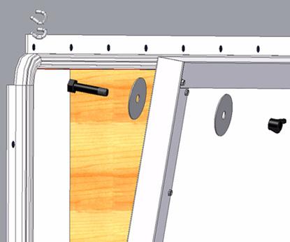
14 Installation Tunnel Door (White) With the Door Assembly in position have one person pull down on the Door to compress the Black P-Seal, and a second person insert #9 x " Quadrex Drive Wood Screws (Item, Figure ) into only the Hinges that are directly under the FRP Panel and attach it to the Door Hinge Board (Item ). In Pre-assembled Door applications this would include all of the Hinges. If Angle the Wood screws down as you put them in to pull the Door down tight to the Black P-Seal. (Item ) When all the Wood Screws are in there should be no daylight showing between the Black P-Seal and the Door (See Figure). Caution: Do not overtighten Wood screws. Only torque until Screw head comes in contact with the Hinge. No Daylight between Door and Black P-Seal #9-" Quadrex Drive Wood screw Door Hinge Board Black P-Seal Figure. Attaching the Door Assembly Put Screws in only the Hinges directly under FRP Panel Skip to page 9 if installing Pre-assembled Doors. End C-Channel Obtain a 0 piece of C-Channel (Item, Figure ) and cut off two 8-/" pieces. Notch Both ends of each 8-/" piece as shown in Figure. Only one of the 8-/ pieces will be used at this time, but set the other one aside and it will be used at the other end later. Important: Make sure that the Cut is precise and accurate. Inaccurate cutting could compromise the performance of the Tunnel Doors and possibly cause a material shortage. 8-/" 8-/" 0 C-Channel 8-/" End Channel -7/8" Figure. Creating End Channel Notch both ends of each End Channel MV89C
. End of Door Typical 6\" Spacing First 8-/\" End Channel Sheet Metal Screw Figure.")
 and angle the bottom left corner down to get")

15 Tunnel Door (White) Installation Attach one of the End C-Channels to the end of the FRP Panel with Sheet Metal Screws using a 6" spacing. (See Figure below). End of Door Typical 6" Spacing First 8-/" End Channel Sheet Metal Screw Figure. Attaching End C-Channel H-Channel between FRP Panels Obtain an H-Channel. (Item, Figure ) H-Channel Figure. H-Channel between FRP Panels Two people, one at each end, Pick up a nd FRP Panel (Item, Figure 5) and angle the bottom left corner down to get it started sliding into the C-Channel with Hinges (Item ) approximately to from the st FRP Panel (Item ) that was installed. Slide the entire FRP Panel down into the C-Channel with Hinges. nd FRP Panel C-Channel w/hinges st FRP Panel Start Corner of FRP Panel in Bottom C-Channel and slide Door down into the Channel Figure 5. Sliding FRP Panel into C-Channel w/hinges MV89C 5


16 Installation Tunnel Door (White) Slip the 5-/" H-Channel pieces (Item, Figure 6) over the st and nd FRP Panel (Items, and ) as shown in Figure 6. Slip H-Channel over second FRP Panel at top corner Slip H-Channel over first FRP Panel at bottom corner Figure 6. Slip H-Channel over FRP Panels 5-/" H- Channel st FRP Panel nd FRP Panel Attaching second FRP Panel Have one person push the nd FRP Panel (Item, Figure 7) towards the st FRP Panel (Item ) while the other person keeps the H-Channel slipping over the FRP Panels as they come together. With the st and nd FRP Panels, and the H-Channel (Item ) pushed tightly together, use Self-Tapping Screws (Item ) every 6" to fasten the Second FRP Panel to the Bottom C-Channel with Hinges (Item 5). Push second Door over tight against H-Channel and st Door nd FRP Panel st FRP Panel 5-/" H- Channel Self-Tapping Screw 5 C-Channel w/hinges 6" Screw Spacing Figure 7. Attach Second FRP Panel to Bottom C-Channel w/hinges 5 Installing a 0 Top C-Channel Slide a 0 Top C-Channel (Item, Figure 8) onto the top of the FRP Panels and push it over until it is flush with the 5 Top C-Channel (Item ). Use a Self-Tapping Screw (Item ) at each end of the 0 Top C-Channel to attach it to the FRP Panels /" from the end and /" up as shown. Use two Self-Tapping Screws 6 MV89C


17 Tunnel Door (White) Installation (Item ) to attach the top C-Channel to the H-Channel as shown.l Push 0 Top C-Channel until flush with 5 Top C-Channel /" /" 0 Top C-Channel 5 Top C-Channel 5-/" H- Channel Self-Tapping Screw 5 C-Channel w/hinges 5 /" /" Figure 8. Attaching 0 Top Channel MV89C 7
 onto the bottom of the Second FRP Panel (Item ). Use an object with a flat surface to tap the 0 C-Channel w/hinges over until it is flush with st 0 C-Channel w/hinges.")
 does not get rolled (See Figure 9).")

18 Installation Tunnel Door (White) Attaching the Second C-Channel with Hinges (0 Channel) Pull slightly out on the end of the Door Assembly and Slide a second 0 Bottom C-Channel w/hinges (Item, Figure 9) onto the bottom of the Second FRP Panel (Item ). Use an object with a flat surface to tap the 0 C-Channel w/hinges over until it is flush with st 0 C-Channel w/hinges. A short x works very well (See Figure 9). Be very careful not to bend or ding the corners of the C-Channel w/hinges. Make sure that the Hinges are all in the down position and that the Black P-Seal (Item ) does not get rolled (See Figure 9). Attach the Second Bottom C-Channel with Hinges to the Second FRP Panel with Self-Tapping Screws (Item ) every 6" out to the end of the Second FRP Panel. Do not attach the Bottom C-Channel with Hinges to the Bottom Hinge Board until after the next FRP Panel is in place. Slide Second 0 Bottom C-Channel w/hinges until flush with st one 6" Typical Use a x or similar flat object to tap Bottom C-Channel w/hinges until it is flush with next C-Channel w/hinges. 0 Bottom C- Channel w/hinges Second FRP Panel Black P-Seal Self-Tapping Screw Figure 9. Attaching the Second 0 Bottom C-Channel w/hinges Do Not allow the Black P-Seal to Roll 8 MV89C
 and a marking utensil.")
.")

 is towards the FRP Panel.")
19 Tunnel Door (White) Installation Installing Flat Washers & Nylon Split Bolt on the st FRP Panel If installing Pre-assembled Doors skip this paragraph because Pre-assembled Doors are pre-drilled. Obtain a Large Flat Washer (Item, Figure 0) and a marking utensil. Place the Large Flat Washer in the upper most corner of the end of the First FRP Panel (Item ) so that it is Flush with the End Channel (Item ) and the Top C-Channel (Item ) and mark the center point of the washer. Drill a /" Hole through the FRP Panel at the Center mark you just made (See Figure ). Install a Large Flat Washer (Item, Figure ) onto a Slotted Nylon Split Bolt (Item 5), and from the back side of the FRP Panel, push it through the /" hole drilled in Figure. Important: The Large Flat Washers are sharp on one side from the manufacturing process. To determine which side is sharp, run your thumb across the inside diameter of the Washer. The sharp side (burr side) must always face towards the FRP Panel or it will cut into the Nylon Rope and Nylon Nut. Install a second Large Flat Washer on the front side of the FRP Panel making sure that the sharp side (burr side) is towards the FRP Panel. Washer Flush with Top C-Channel Washer Flush with End C-Channel Figure 0. Marking center point for hole in FRP Panel Figure. Drilling /" hole in FRP Panel Large Flat Washer First FRP Panel End C-Channel Top C-Channel 5 Nylon Split Bolt 5 Figure. Installing Large Flat Washers Burr side of Washer towards FRP Panel MV89C 9

 into the slot in the end of the Nylon Split Bolt (Item ) leaving approximately 6\"-\" at the end as shown.")
 /\" above the top edge of the Top C-Channel (Item ) (measure with the door closed).")
20 Installation Tunnel Door (White) Installing Nylon Rope on st FRP Panel to temporarily hold Door(s) in place If installing continuous Doors they will soon become too heavy to handle and should be temporarily tied up to ease assembly and keep the Doors from coming down unexpectedly. To do this, obtain the Nylon Rope and cut off a 6 piece. Burn the ends to keep the rope from fraying. Put a Knot (See Figure ) in the end of the Nylon Rope. Push the knotted end of the 6 Nylon Rope (Item ) into the slot in the end of the Nylon Split Bolt (Item ) leaving approximately 6"-" at the end as shown. Put on a Split Bolt Cap (Item ) and hand tighten. Caution: Do Not use tools of any kind to tighten the Split Bolt Cap. Using tools could over torque the Split Bolt Cap and Nylon Split Bolt. 6-" Knot Figure. Installing Rope on st FRP Panel Install an Eyehook (Item, Figure ) /" above the top edge of the Top C-Channel (Item ) (measure with the door closed). Screw the Eyehook in until the open end is nearly touching the wall. If the Winch operating the Tunnel Doors is going to be pulling from the left, turn the hook to a 5 angle to the Door (See Figure ). If the Winch is to located at the right end of the system, then the Eyehook should be at a 5 angle (See Figure 5). Winch Winch 5 5 /" /" Figure. Eyehook for Tunnel Doors with Winch to the left Eyehook Top C-Channel Figure 5. Eyehook for Tunnel Doors with Winch to the right 0 MV89C
 does not line up with a Wall Stud, angle the Eyehook down into the Door Header as shown, making sure that the center of the Eyehook when it is screwed in")
.")
.")
21 Tunnel Door (White) Installation Make sure that Eyehook is in Solid Wood Make sure that the Eyehook is in solid wood because it will be supporting a substantial amount of weight. If the Eyehook (Item, Figure 6) does not line up with a Wall Stud, angle the Eyehook down into the Door Header as shown, making sure that the center of the Eyehook when it is screwed in is /" above the top of the Top C-Channel (Item ). If the Winch is located at the left of the system, turn the hook to a 5 angle to the Door (See Figure ). If the Winch is to located at the right end of the system, then the Eyehook should be at a 5 angle (See Figure 5). It may be necessary to angle Eyehook down to hit solid wood /" when Eyehook is screwed in Eyehook Top C-Channel Figure 6. Make Sure Eyehook is in solid wood Use a pair of Adjustable Pliers to squeeze the Eyehook closed (See Figure 7). Insert the loose end of the Nylon Rope through the Eyehook and with the Doors open approximately 6", tie a temporary knot to support the Doors. (See Figure 7) Temporary Knot Squeeze Eyehook Closed Eyehook Figure 7. Squeeze Eyehook and tying Nylon Rope MV89C
, 6 Nylon Ropes (Item ), Split Bolt Caps (Item 5), and Eyebolts (Item 6) at each hole as done in Figures, and.")
22 Installation Tunnel Door (White) Installing Nylon Rope at remaining Hole locations (Pre-assembled Door application only) If installing continuous Doors skip to next page "Continuing to add FRP Panels and Temporary Tie-ups" Install Large Flat Washers, Nylon Split Bolts (Item, Figure 8), 6 Nylon Ropes (Item ), Split Bolt Caps (Item 5), and Eyebolts (Item 6) at each hole as done in Figures, and. At this time, thread the Nylon Ropes through the Eyehooks and let them hang loose. Flat Washer Top C-Channel Nylon Split Bolts Nylon Rope 5 Split Bolt Cap 6 Eyebolt Figure. Installing Remaining Nylon Ropes (Pre-assembled Doors) 6 5 Washer Flush with bottom of Top C-Channel Figure 8. Installing Nylon Rope (Pre-assembled Doors) Skip to the "Installing Control Wire Eyehooks" section on page 6 to continue installation of Pre-assembled Doors. MV89C


23 Tunnel Door (White) Installation Continuing to add FRP Panels and Temporary Tie-ups Important: As more FRP Panels are added to the Door Assembly the Doors will become heavy. Make sure that you read the following directions very carefully for tying up the Doors to avoid injury and damage to the Tunnel Doors. Continue to add on FRP Panels, C-Channels, H-Channels, and C-Channels with Hinges as you did in Figures 5 through 9. As you continue, the Tunnel Doors need to be tied up at least every 0 to allow for easy assembly, and to avoid having the Doors open suddenly causing damage to the Doors or injury. If the Tunnel Doors are going to be left un-attended during assembly, do not leave more than 0ft between the last Tie-up and the end of Door Assembly. Obtain a Flat Washer (Item, Figure 9) and while holding it flush with the Bottom of the Top C-Channel (Item ), and lined up with the center of the Wall Stud, mark and drill a /" hole in the FRP Panel for a Nylon Split Bolt (Item ) to be installed. Install a Nylon Split Bolt, Flat Washers, a Split Bolt Cap, (Item ), an Eyehook, and use a 6 Nylon Rope (Item 5) to tie the Doors up exactly as you did in Figures -7. Important: The Large Flat Washers are sharp on one side from the manufacturing process. To determine which side is sharp, run your thumb across the inside diameter of the Washer. The sharp side (burr side) must always face towards the FRP Panel or it will cut into the Nylon Rope and Nylon Nut. Wall Stud Flat Washer Flush with Top C-Channel and lined up with Center of Wall Stud Eyehook and Nylon Split Bolt centered on Wall Stud 5 Maximum of 0 between temporary Tie-ups Large Flat Washer Top C-Channel Nylon Split Bolt Split Bolt Cap 5 6 Nylon Rope Figure 9. Temporary Tie-ups MV89C
.")
24 Installation Tunnel Door (White) Cutting off last FRP Panel Once the end of the rough opening has been reached it may be necessary to cut off the last FRP Panel (Item, Figure 0). Measure and Cut the FRP Panel so that it is Flush with the outside of the bulb of the White P- Seal (Item ). Cut off FRP Panel Flush with outside of White P-Seal Bulb Last FRP Panel White P-Seal Figure 0. Cutting off last FRP Panel Attaching the End C-Channel, Top C-Channel and Bottom C-Channel with Hinges to the Last FRP Panel Obtain the 5 Top C-Channel (Item, Figure ) and 5 C-Channel w/hinges that you cut earlier and attach them to the last FRP Panel with Self-Tapping Screws spaced every 6". It may be necessary to cut the C- Channels so that they are flush with the end of the Last FRP Panel. Obtain the second 8-/ piece of End C- Channel (Item ) cut earlier in Figure and attach it with Self-Tapping Screws exactly the same as the End C-Channel at the beginning of the Tunnel Door run (See Figure ). Top C-Channel Flush with end of last FRP Panel 5 Top C-Channel 5 Bottom C-Channel w/hinges nd End C-Channel Figure. End C-Channel, Top C-Channel, and Bottom C-Channel w/hinges (Last FRP Panel) Bottom C-Channel w/hinges Flush with end of last FRP Panel MV89C
 so that it is Flush with the End Channel (Item ) and the Top C-Channel (Item ) and mark the center point")

25 Tunnel Door (White) Installation Installing Flat Washers & Nylon Split Bolt on the Last FRP Panel Obtain a Large Flat Washer (Item, Figure ) and a marking utensil. Place the Large Flat Washer in the upper most corner of the end of the last FRP Panel (Item ) so that it is Flush with the End Channel (Item ) and the Top C-Channel (Item ) and mark the center point of the washer. Drill a /" Hole through the FRP Panel at the Center mark you just made (See Figure ). Install two Flat Washers, a Nylon Split Bolt and a Split Bolt Cap exactly the same as you did in Figures 0-. Washer Flush with Top C-Channel Washer Flush with End C-Channel Figure. Drilling /" hole in Last FRP Panel Figure. Marking center point for hole in Last FRP Panel Large Flat Washer Last FRP Panel End C-Channel Top C-Channel MV89C 5
.")
26 Installation Tunnel Door (White) Installing remaining Nylon Ropes Nylon ropes need to be attached to the FRP Panels at every Wall Stud throughout the entire length of Tunnel Doors (except where the Doors were previously tied up). Obtain Flat Washers (Item, Figure ) and while holding them flush with the Bottom of the Top C-Channel (Item ), and lined up with the center of each Wall Stud, mark and drill a /" holes in the FRP Panels for Nylon Split Bolts (Item ) to be installed just like you did in Figures 0, and. Install Large Flat Washers, Nylon Split Bolts, 6 Nylon Ropes (Item ) and Split Bolt Caps (Item 5) at each hole as done in Figures, and. At this time, thread the Nylon Ropes through the Eyehooks and let them hang loose. Line up Nylon Split Bolt, Flat Washers, and Nylon Split Bolt with center of Wall Studs Flat Washer Top C-Channel Nylon Split Bolts Nylon Rope 5 Split Bolt Cap Figure. Installing Remaining Nylon Ropes 5 Washer Flush with bottom of Top C-Channel Control Wire Eyehooks At the center of every Wall Stud, screw in a second Eyehook (Item, Figure 5) /" above the first, but only screw it in to the end of the threads. This Eyehook will be used to run Control Wire through horizontally, so leave it at 90 to the Top C-Channel (Item ) with the open end of the Eyehook up as shown. Control Wire Eyehook straight above st Eyehook at each Wall Stud Screw in Control Wire Eyehook only to end of threads Control Wire Eyehook Top C-Channel Figure 5. Installing Remaining Nylon Ropes /" between Eyehooks 6 MV89C
 while a second person feeds it through the Control Wire Eyehooks (Item ).")

27 Tunnel Door (White) Installation Control Wire Installation At the Winch end of the Tunnel Doors, have someone hold and unroll the Roll of Control Wire (Item, Figure 6) while a second person feeds it through the Control Wire Eyehooks (Item ). It is very important to not let the Control Wire get any bends or kinks in it. Cut off the Control Wire with a minimum of 5 extra at each end of the Tunnel Door run and put a 90 bend in the wire /" from both ends (See Figure below) 5 Minimum both ends Bend 90 /" st Eyehook.5 Cable Clamp Winch Cable Control Wire Figure 6. Control Wire Installation MV89C 7

. Use four Cable Clamps rotated 80 to each other exactly as shown in Figure 7 below.")

28 Installation Tunnel Door (White) Attaching Control Wire to Cable (Winch End) It would be impossible to show every way to cable the Tunnel Doors. Shown below is one way using a Linear Lift, Double-Back Pulleys, and a Hand Winch mounted on the end wall. The Winch is pulling from the right in the Side Wall View. There must be a distance equal to or greater than the desired Tunnel Door actuation between the st Eyehook (Item ) and the st Cable Clamp (Item ) connecting the Winch Cable (Item ) to the Control Wire (Item ). Use four Cable Clamps rotated 80 to each other exactly as shown in Figure 7 below. Desired Tunnel Door Actuation Distance Minimum Distance = Desired Tunnel Door Actuation Distance Control Wire Cable from Winch Desired Tunnel Door Actuation to first Clamp Side Wall View Alternate Cable Clamps 80 st Eyehook.5 Cable Clamp Winch Cable Control Wire Doubleback Pulley To Control Wire Lift Doubleback Pulley To Control Wire Figure 7. Winch Hook-Up Hand Winch End Wall View Hand Winch 57-0 DANGER Rotating Parts! Do not operate with covers removed! DISCONNECT ELECTRICAL POWER BEFORE WORKING ON SYSTEM, EQUIPMENT MAY START AUTO- MATICALLY. OTHERWISE SEVERE PERSONAL INJURY WILL RESULT. 8 MV89C
29 Tunnel Door (White) Installation Installing Counter Weight (Concrete Block) Now that the Control Wire is attached to the Winch Cable it is time to install a counterweight at the other end of the Tunnel Door run. Run the Linear Lift to the fully open position (Brass Nut (Item ) opposite the Motor end, if using a Chore Time Linear-Lift ) (See Figure 8 below). There must be a distance atleast " greater than the desired Tunnel Door actuation between the last Eyehook (Item ) and the st Cable Clamp (Item ) connecting the Control Wire (Item ) to the Counterweight Cable (Item 5) Mount the st pulley a minimum of 9" for desired actuation and 6" for 5 desired actuation away from the last Eyehook to allow full actuation of the Control Wire. Use pulleys to get the cable elevated high enough to allow for: Desired Tunnel Door actuation, plus the height of the Counterweight (Concrete Block), plus to keep the Counterweight above Chickens (See Figure 8). Set the Counterweight on something to elevate it just above Chicken height and attach a cable to it. Thread the cable up through the pulleys and use four Cable Clamps rotated 80 to each other to attach the end of the Counterweight Cable to the Control Wire as close to the st Pulley as possible. Use the Hand Winch to tighten up the Control Wire and then check to make sure there is still the distance for actuation between the last Eyehook and the st Cable Clamp. 5 Minimum Distance from last Eyehook to st Cable Clamp when tight = (9" for desired actuation) (6" for 5 desired actuation) Run Linear-Lift until Brass Nut is opposite Motor end Alternate Cable Clamps 80 Brass Nut Last Eyehook.5 Cable Clamp Control Wire 5 Counterweight Cable Minimum Distance = Desired Tunnel Door Actuation ( or 5 ) Counterweight Height Figure 8. Installing Counterweight MV89C 9
 mounted to the wall with Pulley Brackets (Item ) (CT Part No. 505), U-Bolt (Item ) (CT Part No. 560), and a Pulley (Item ) (CT Part No. 500).")
30 Installation Tunnel Door (White) Installing Counter Weight (Spring) A Tension Spring may be used instead of a counterweight if desired. Shown below is a Tension Spring (Item, Figure 9) (CT Part No. 7958) mounted to the wall with Pulley Brackets (Item ) (CT Part No. 505), U-Bolt (Item ) (CT Part No. 560), and a Pulley (Item ) (CT Part No. 500). Run the Linear Lift to the fully open position (Brass Nut (Item 5) opposite the Motor end, if using a Chore Time Linear-Lift ) (See Figure 9 below). Mount the Tension Spring with the minimum distance requirements shown below. Attach the Counterweight Cable (Item 6) (not included) to the Control Wire (Item 7) with four Cable Clamps (Item 8) rotated 80 from each other as shown. Use the Hand Winch to tighten the Control Wire until the Tension Spring is stretched to " in length. Make sure that there is still the minimum distance (9" for desired actuation, or 6" for 5 desired actuation) between the Last Eyehook (Item 9) and the st Cable Clamp. 7 8 Alternate Cable Clamps 80 5 Brass Nut run all the way opposite the Motor end 6 9 Minimum Distance from last Eyehook when tight to st Cable Clamp= (9" for desired actuation) (6" for 5 desired actuation) Spring Stretched to " with Linear Lift in open position Minimum distance = (" for desired actuation) (0" for 5 desired actuation) Tension Spring Pulley Bracket U-Bolt Pulley 5 Brass Nut 6 Counterweight Cable 7 Control Wire 8 Cable Clamp 9 Last Eyehook Figure 9. Installing Counterweight (Spring) 0 MV89C
. Now it is time to attach Nylon Ropes to the Control Wire (Item ). The Nylon Ropes support the weight of the Doors and control how far they actuate.")
 and over to the Second Control Wire Eyehook (Item 5). It may be necessary to loosen the Split Bolt Cap.")
31 Tunnel Door (White) Installation Attaching Nylon Ropes to Control Wire Run the Winch all the way to the closed position (Brass Nut (Item, Figure 0) toward the Motor end, if using a Chore Time Linear-Lift ). Now it is time to attach Nylon Ropes to the Control Wire (Item ). The Nylon Ropes support the weight of the Doors and control how far they actuate. Locate the st Nylon Rope (Item ) on the FRP Panel that is opposite the Winch end and untie it if necessary. Thread the Rope through the Bottom Eyehook (Item ) and over to the Second Control Wire Eyehook (Item 5). It may be necessary to loosen the Split Bolt Cap. If the measurement between these Eyehooks is not atleast equal to the desired Tunnel Door actuation (8" or 60") see Figure on the following page. Tie a knot (Item 6) in the end of the Nylon Rope. Use a Cable Clamp (Item 7) to attach the Nylon Rope to the Control Wire as close to the Control Wire Eyehook as possible. Make sure that the Nylon Rope creates a straight line and is not looped over or around the Control Wire. Orient the Cable Clamp exactly as shown in Figure 0 for proper bite into the Control Wire. It is very important to get the Cable Clamp Nuts tight as they are required to support the weight of the Tunnel Doors. Attach the rest of the Nylon Ropes throughout the entire Tunnel Door run in the same manner Brass Nut toward Motor end Brass Nut Control Wire Nylon Rope Bottom Eyehook 5 Control Wire Eyehook Winch towards the Right 6 Knot 7 Cable Clamp Figure 0. Attaching Nylon Ropes to Control Wire MV89C
 toward the Motor end, if using a Chore Time Linear-Lift ).")
. Tie Knots at each end of the Nylon Rope.")
32 Installation Tunnel Door (White) Attaching Nylon Ropes to Control Wire (if there is less than desired actuation distance between Control Wire Eyehooks) Run the Winch all the way to the closed position (Brass Nut (Item, Figure ) toward the Motor end, if using a Chore Time Linear-Lift ). If the distance between Control Eyehook and Control Eyehook is less than the desired Tunnel Door actuation (See Figure), then the following instructions apply. Cut a piece of Nylon rope x desired actuation + (5 actuation = rope). Tie Knots at each end of the Nylon Rope. Replace the shorter Nylon Rope attached to the st Nylon Split Bolt (Item ) in the Corner of the st FRP Panel earlier. Thread the new, longer Nylon Rope (Item 5) through the st Bottom Eyehook (Item 6), then through the nd Bottom Eyehook (Item 7), and allow the rope to hang. Thread the nd shorter Nylon rope attached to the FRP Panel through the Bottom Eyehook above it and tie a knot at the end of it. Take both the longer Nylon Rope and the shorter Nylon Rope and attach them to the Control Wire with a Cable Clamp (Item 8) as close to the rd Control Wire Eyehook (Item 9) as possible. Make sure that the Nylon Ropes create straight lines and are not looped over or around the Control Wire when tight. Orient the Cable Clamp exactly as shown in Figure for proper bite into the Control Wire. It is very important to get the Cable Clamp Nuts tight because they will be supporting a substantial amount of weight. Loosen both the st and nd Split Bolt Caps and pull down on both Nylon Ropes as hard as you can to pull the Doors tight against the seal. Re-tighten the Split Bolt Caps. To attach the Nylon Ropes to the Control Wire when spacing between Control Wire Eyehooks is equal to the desired Tunnel Door actuation see Figure 0 on the previous page. Cable Clamp Nuts 5 7 toward Control Wire Distance less than desired Tunnel Door actuation 5 Brass Nut Control Eyehook Control Eyehook st Nylon Split Cap 5 Longer Nylon Rope 6 st Bottom Eyehook 7 nd Bottom Eyehook 8 Cable Clamp 9 rd Control Wire Eyehook Brass Nut toward Motor end Figure. Attaching Nylon Ropes to Control Wires with less than desired actuation distance MV89C
 Run the Winch all the way to the closed position (Brass Nut (Item, Figure 0) toward the Motor end, if using a Chore Time Linear-Lift ).")
, then the following instructions apply. Attach two Pulleys (Item ) (Chore-Time part no.")
. Tie Knots at the ends of both Nylon Ropes.")
 90 as shown.")
 as possible (See Figure). 8 6 7 7 5 5 Figure.")
33 Tunnel Door (White) Installation Attaching Nylon Ropes to Control Wire (if there is less than desired actuation distance between Control Wire Eyehooks and also less than desired actuation distance to the wall) Run the Winch all the way to the closed position (Brass Nut (Item, Figure 0) toward the Motor end, if using a Chore Time Linear-Lift ). If the distance between the last two Control Eyehooks is less than the desired Tunnel Door actuation, and there is less than the desired actuation distance between the last Bottom Eyehook and the wall (See Figure ), then the following instructions apply. Attach two Pulleys (Item ) (Chore-Time part no. 577) left of the rd Control Eyehook from the end (Item ) with a Lag Screw (Item ) and Washers used for spacers (Item ) as shown. Cut two pieces of Nylon rope x desired actuation + (5 actuation = rope). Tie Knots at the ends of both Nylon Ropes. Replace both the nd to last and last Nylon Ropes attached earlier with the new Longer ones (Item 5). Thread both longer ropes through the Lower Eyehooks above them, around the Pulleys and let it hang temporarily. Turn the rd lower Eyehook from the end (Item 6) 90 as shown. Thread the rd Nylon rope from the end (Item 7) through the lower Eyehook above it and use a Cable Clamp (Item 8) to attach it and the two new Longer Ropes to the Control Wire, as close to the nd Control Wire Eyehook from the end (Item 9) as possible (See Figure) Figure. Attaching Nylon Ropes to Control Wire Less than desired actuation distance Less than desired actuation distance between the last Bottom Eyehook and the Wall Figure. Attaching Nylon Ropes to Control Wire (less than desired actuation distance between Eyehooks and too close to wall) Pulley (not provided) rd Control Wire Eyehook from end Lag Screw (not provided) Washer (not provided) 5 Longer Rope (x desired actuation + ) 6 rd Lower Eyehook from end 7 rd Nylon Rope from end 8 Cable Clamp 9 nd Control Wire Eyehook from end MV89C
 and pull down on the Nylon Ropes (Item ) as hard as you can; then re-tighten the Nylon Split Bolt Caps.")
 to get a good hold on the Nylon Ropes and this will also be easier on your hands.")
34 Installation Tunnel Door (White) Tighten down Nylon Ropes and Final Adjustments To insure a tight sealing Tunnel Door all of the Nylon Ropes need tightened down. Loosen the Nylon Split Bolt Caps (Item, Figure ) and pull down on the Nylon Ropes (Item ) as hard as you can; then re-tighten the Nylon Split Bolt Caps. The White P-Seal (Item ) should be compressed and there should be no daylight showing across the top of the Doors. We recommend that you use Vice Grips (Item ) to get a good hold on the Nylon Ropes and this will also be easier on your hands. White P-Seal should be Compressed and NO light showing across the top of the Doors Nylon Split Bolt Cap Nylon Rope White P-Seal Vice Grips Figure. Tightening down Nylon Ropes MV89C

 to caulk the cracks between the")


35 Tunnel Door (White) Installation Caulking In order to maximize proper Airflow of your new Tunnel Doors it is necessary to Caulk some of the cracks between the Channels. Use Silicone Caulk (preferably white) to caulk the cracks between the End C-Channel (Item, Figure ) and the Top C-Channel (Item ) at both ends of the system. Caulk between the H-Channel (Item ) and the Top C-Channel. Caulk between the H-Channel and the Bottom C-Channel with Hinges (Item ). Caulking End C-Channel Top C-Channel H-Channel Bottom C-Channel w/hinges Caulking Figure. Caulking MV89C 5
")

36 Itemized Parts (Continuous Doors) Tunnel Door (White) Itemized Parts (Continuous Doors) Figure 5. Part Numbers (Continuous Doors) 6 MV89C
37 Tunnel Door (White) Part Numbers (Continuous Doors) Part Numbers (Continuous Doors) Part No. x 0 FRP Panel PVC C-Channel 506- PVC H-Channel Bottom Channel w/hinges White P-Seal Black P-Seal D x Galv. Roofing Nail HXWH SFTP 0-6 x.6 Screw #9-9 x " Quad Drive Wood Screw 50 0 Eyehook Nylon Rope (Not Shown) 5-77 Large Flat Washer 50 Nylon Split Bolt 506 Split Bolt Cap Actuator Wire (500 Roll) Not Shown Cable Clamp (Not Shown) 898 MV89C 7

38 Itemized Parts and Part Numbers (Pre-assembled Doors) Tunnel Door (White) Itemized Parts and Part Numbers (Pre-assembled Doors) 6 5 Models Item Part No. Description QTY.* QTY.* QTY.* QTY.* QTY.* QTY.* x 8 x 5 FRP Panel x 8 x 96 FRP Panel x 60 x 8 FRP Panel " PVC C-Channel " x 60" PVC C-Channel -- ST05.5 x.5 Hinge Pop Rivet.875 x x.8 x.05 Washer HXWH SFTP 0-6 x.6 Screw Decal H-Channel *Quantities shown are per Door. 8 MV89C
39 Tunnel Door (White) Optional Parts Listing Optional Parts Listing Part No. Corner Pulley Assembly 5597 Double Pulley Assembly 777 Pulley Kit 70 Center Pulley Assembly 70 5 /6" Cable (50') 7 x 9 /" Cable galvanized 7 x /6" Cable Clamp 7 7 Pulley Assembly Double Pulley Mounting Brkt Single Pulley Mounting Brkt /6-8x7" U Bolt with Nuts 560 5/6-8x7" Bolt -0 Double Eye Pulley Nylon Pulley # Tension Spring Pulley Assembly " Steel Double Pulley Assembly 9 7.5" Steel Pulley Assembly " Steel Single Pulley Assembly 8 Figure 7. Optional Part Numbers MV89C 9
40 Optional Parts Listing Tunnel Door (White) Note: The original, authoritative version of this manual is the [English] version produced by CTB, Inc. or any of its subsidiaries or divisions, (hereafter collectively referred to as "CTB"). Subsequent changes to any manual made by any third party have not been reviewed nor authenticated by CTB. Such changes may include, but are not limited to, translation into languages other than [English], and additions to or deletions from the original content. CTB disclaims responsibility for any and all damages, injuries, warranty claims and/or any other claims associated with such changes, inasmuch as such changes result in content that is different from the authoritative CTB-published [English] version of the manual. For current product installation and operation information, please contact the customer service and/or technical service departments of the appropriate CTB subsidiary or division. Should you observe any questionable content in any manual, please notify CTB immediately in writing to: CTB Legal Department, P.O. Box 000, Milford, IN USA. Revisions to this Manual Page No. Description of Change Added (White) to description on main page. Contact your nearby Chore-Time distributor or representative for additional parts and information. CTB Inc. P.O. Box 000 Milford, Indiana U.S.A. Phone (57) Fax (877) Internet: http// Printed in the U.S.A. 0 MV89C
Tunnel Door Installation & Operator s Instruction Manual
 Tunnel Door Installation & Operator s Instruction Manual March 006 MV89A Chore-Time Warranty Tunnel Door Chore-Time Warranty Chore-Time Equipment ( Chore-Time ) warrants each new Chore-Time product manufactured
Ventilation System. Installation Manual. Hog Slat Inc. Newton Grove, NC USA March
 Installation Manual 1 Tunnel Door Framing Instructions It is import to make sure the Tunnel Door opening is flat and plumb. A maximum variation of +/- ½ throughout the length of the opening is acceptable.
Linear Lift Cable to Chain Retrofit Instruction Kit Part No Series.
 Linear Lift Kit Part No. 50558-Series. The employees of Chore-Time Equipment would like to thank your for your recent Chore-Time purchase. If a problem should arise, your Chore-Time distributor can supply
INSTALLATION INSTRUCTIONS
 INSTALLATION INSTRUCTIONS Universal Short Throw Projector Arm Model: UNI-STA/UNI-EXT NORTH AMERICA 3130 East Miraloma Avenue Anaheim, CA 92806 USA USA and Canada Phone: 1-800-368-9700 Fax: 1-800-832-4888
Single-Sliding Header Mount INSTALLATION INSTRUCTIONS
 1-800-701-4782 Single-Sliding Header Mount INSTALLATION INSTRUCTIONS GATEWAY SO# OPENING SIZE: W x H PULLEY SYSTEM: YES / NO Upon receiving your Gateway Door, inspect packaging and contents for freight
PATRIOT DOCKS ASSEMBLY INSTRUCTIONS
 6/1/2008 PATRIOT DOCKS ASSEMBLY INSTRUCTIONS Congratulations on your new Patriot Dock purchase. This manual contains instructions to assemble basic dock configurations for use at typical shoreline application.
HOUSE PARTS PACKED IN HOUSE BOX PARTS IN PLASTIC BAG (HARDWARE) PARTS IN SMALL PLASTIC BAG (FLOOR CLIPS) PARTS PACKED IN BUNDLE
 PARTS IN SMALL PLASTIC BAG (FLOOR CLIPS) PARTS PACKED IN BUNDLE") Check parts against this list before starting assembly. Refer to illustrations on pages 6 and 7 to view house parts. If any shortages are found, refer to Packing Slip for claim instructions. Item 3 5 6
Check parts against this list before starting assembly. Refer to illustrations on pages 6 and 7 to view house parts. If any shortages are found, refer to Packing Slip for claim instructions. Item 3 5 6
Installation and Assembly: Articulating Swivel Arm for 37" - 60" Flat Panel Displays
 Installation and Assembly: Articulating Swivel Arm for 37" - 60" Flat Panel Displays Models: PLA60, PLA60-S, PLAV60, PLAV60-S Max UL Load Capacity: 175 lb (79 kg) 2300 White Oak Circle Aurora, Il 60502
Specifications. Important Safety Information
 Specifications Tire Rim Capacity 4 to 12 Rim Height 16 (2) Bead Breaker Handles 21 Long Includes Aluminum Centering Cone (2) Nylon Spacers Important Safety Information 1. Do not exceed max. tire capacity.
AST-2446 INSTALLATION INSTRUCTIONS
 AST-2446 Suspension Adapter AST-2446 INSTALLATION INSTRUCTIONS Single Stud Installation Step 1. Secure the ceiling plate to the ceiling structure (see WARNING). Step 2. Use suitable hardware (commercially
Please Do Not Return This Product To The Store!
 MODEL NOS. T8512 TOURNAMENT SERIES 3 TABLE TENNIS TABLE OWNER'S MANUAL 1. Read this manual carefully before starting assembly. Read each step completely before beginning each step. 2. Some smaller parts
00108/00110 INSTRUCTION MANUAL
 00108/00110 INSTRUCTION MANUAL Removable and Adjustable Mudflap System IMPORTANT! Please Read this Instruction Booklet prior to assembly of your Rock Tamer Kit. IMPORTANT! Exhaust Systems Note: Any modifications
Please Do Not Return This Product To The Store!
 MODEL NOS. T81 TABLE TENNIS TABLE OWNER'S MANUAL 1. Read this manual carefully before starting assembly. Read each step completely before beginning each step.. Some smaller parts may be shipped inside
INSTALLATION INSTRUCTIONS
 CREATING POSITIVE CUSTOMER EXPERIENCES INSTALLATION INSTRUCTIONS Universal Low Profile Tilt Mount for 42 to 63 Flat Panels NORTH AMERICA 3130 East Miraloma Avenue Anaheim, CA 92806 USA USA and Canada Phone:
MM540 Installation Instructions IMPORTANT SAFETY INSTRUCTIONS - SAVE THESE INSTRUCTIONS
 MM50 Installation Instructions IMPORTANT SAFETY INSTRUCTIONS - SAVE THESE INSTRUCTIONS Please read this entire manual before you begin. Do not unpack any contents until you verify all requirements on PAGE.
MFJ-1835K34 40,30 METER ADD ON KIT FOR THE MFJ-1835 COBWEB ANTENNA INSTRUCTION MANUAL. CAUTION: Read All Instructions Before Operating Equipment
 MFJ-1835K34 40,30 METER ADD ON KIT FOR THE MFJ-1835 COBWEB ANTENNA INSTRUCTION MANUAL CAUTION: Read All Instructions Before Operating Equipment 300 Industrial Park Road Starkville, MS 39759 USA Tel: 662-323-5869
Please Do Not Return This Product To The Store!
 MODEL NO. T8176 QUICK SERVE 3000 TABLE TENNIS TABLE OWNER'S MANUAL 1. Read this manual carefully before starting assembly. Read each step completely before beginning each step. 2. Some smaller parts may
MODEL 83 Pail Handler
 MORSE MFG. CO., INC. 727 West Manlius Street P.O. Box 518 East Syracuse, NY 13057-0518 Phone: 315-437-8475 Fax: 315-437-1029 Email: service@morsemfgco.com Website: www.morsemfgco.com COPYRIGHT 2005 MORSE
Spa & Hot Tub Necessities. Cover Removal System Installation & Use Manual
 Spa & Hot Tub Necessities Cover Removal System Installation & Use Manual SET-UP AND ASSEMBLY BEFORE BEGINNING ASSEMBLY, CAREFULLY READ THE FOLLOWING INFORMATION AND INSTRUCTIONS: Place all parts in a cleared
MM340 Installation Instructions IMPORTANT SAFETY INSTRUCTIONS - SAVE THESE INSTRUCTIONS
 MM30 Installation Instructions IMPORTANT SAFETY INSTRUCTIONS - SAVE THESE INSTRUCTIONS Please read this entire manual before you begin. Do not unpack any contents until you verify all requirements on PAGE.
Mount to the Wall INSTALLATION MANUAL
 Mount to the Wall 15 Locate the Wooden Studs This step applies to wooden stud wall installation only. Determine and mark the exact locations of two stud centers on the wall. Wooden studs should be spaced
Models 2230 and 2240
 Models 2230 and 2240 Overview... 2 Tools Needed... 2 Hardware...3 Assembly... 4-13 Installation... 14 Drawer Removal... 15 Operation... 15 Maintenance... 15 Accessories... 16 Limited Warranty... 16 Perform
Models 2130 and 2140
 Models 2130 and 2140 Overview... 2 Tools Needed... 2 Hardware... 2 Assembly... 3-10 Installation...11 Operation... 11 Maintenance... 12 Accessories...12 Limited Warranty... 12 Printed in USA 2007 Perform
Tilting, Swiveling & Rotating Flat Panel Wall Mount
 Tilting, Swiveling & Rotating Flat Panel Wall Mount Model: VXA980TC +5 to -5 +5 to -5 Supports most 0-80 Flat Panel TVs Maximum Weight Capacity: 32 lbs. Supports VESA Sizes up to 600x500 For technical
GearBoss AirPro Locker
 Installation and Owner s Instructions GearBoss AirPro Locker Wall Installation Island Installation Contents Important User Information...........................2 General...2 Manufacturer...2 Intended
RAMPAGE P R O D U C T S. BRONCO ZIPPER FASTRACK TOP PART #984xx BRONCO TOOLS REQUIRED
 RAMPAGE P R O D U C T S 84 (+/- 1/4 ) BRONCO ZIPPER FASTRACK TOP PART #984xx BRONCO 1966-1977 TOOLS REQUIRED 3/8 WRENCH 7/16 WRENCH ½ WRENCH #2 PHILLIPS SCREWDRIVER 1/8 DRILL BIT 9/64 DRILL BIT 5/32 DRILL
Tilting Flat Panel Wall Mount Installation Guide
 Tilting Flat Panel Wall Mount Installation Guide Model: A580TM Easy installation Built-in level for easy positioning Safety bolts lock the TV on the mount Easy to adjust tilt angles: +5 to -15 degrees
INSTALLATION INSTRUCTIONS
 CREATING POSITIVE CUSTOMER EXPERIENCES INSTALLATION INSTRUCTIONS PDS-PLUS Universal Projector Mount Model: NORTH AMERICA 3130 East Miraloma Avenue Anaheim, CA 92806 USA USA and Canada Phone: 1.800.368.9700
MPA-9000 Universal Ceiling Projector Mount Kit
 I N S T R U C T I O N M A N U A L Universal Ceiling Projector Mount Kit The Universal Ceiling Projector Mount provides a unique, simplified method of ceiling mounting your inverted projector. This low
Installation Guide. Tel: (519) Railway St. P.O Box 668 Seaforth, ON Canada N0K 1W0
 Railway St. P.O Box 668 Seaforth, ON Canada N0K 1W0") Installation Guide Tel: (519) 527-2470 92 Railway St. P.O Box 668 Seaforth, ON Canada N0K 1W0 www.sunnorth.com Table of Contents...1 I. Table of Contents... 2 II. Installation Preparation... 2 Items Included...
Installation Guide Tel: (519) 527-2470 92 Railway St. P.O Box 668 Seaforth, ON Canada N0K 1W0 www.sunnorth.com Table of Contents...1 I. Table of Contents... 2 II. Installation Preparation... 2 Items Included...
Parts list continues on Page 2 HOUSE PARTS PACKED IN HOUSE BOX PARTS IN SMALL PLASTIC BAG (HARDWARE) POST PARTS PACKED IN THIS BOX (LARGE PLASTIC BAG)
 POST PARTS PACKED IN THIS BOX (LARGE PLASTIC BAG)") Form 05-07 Instructions and Parts List MSS- Martin Safety System NOTES: () A complete system is packed in two boxes post box and house box. House box contains hardware for both post and house assembly.
Form 05-07 Instructions and Parts List MSS- Martin Safety System NOTES: () A complete system is packed in two boxes post box and house box. House box contains hardware for both post and house assembly.
Loading Dock Safety Gate
 Installation Instructions/Operation and Maintenance Manual Models LDSG-120-PCY LDSG-144-PCY Table of Contents Product Information...2 Parts List...3 Installation Instructions...5 Operation...13 Inspection
Installation Instructions Hinged Roof Rack
 Installation Instructions Hinged Roof Rack Application: Jeep Wrangler Unlimited 2004 - Current Part Number: 41435-01 www.bestop.com - We re here to help! Visit our web site and click on Ask a Question
OWNER'S MANUAL. Please Do Not Return This Product To The Store!
 MODEL NO. T8190SA TABLE TENNIS TABLE OWNER'S MANUAL 1. Read this manual carefully before starting assembly. Read each step completely before beginning each step.. Some smaller parts may be shipped inside
Elo Touch Solutions Wallmounting Kit for the 7001L IDS Touchmonitors
 Installation Manual Elo Touch Solutions Wallmounting Kit for the 7001L IDS Touchmonitors SW602083 Rev E Table of Contents Chapter 1: Safety Warning... 3 Chapter 2: Kit Contents... 4 Included in Kit...
Models 2030 and 2040
 Models 2030 and 2040 Overview... 2 Tools Needed... 2 Hardware... 2 Assembly... 3-8 Installation... 9 Operation... 9 Maintenance... 10 Accessories... 10 Limited Warranty... 10 Document # 101290 0607 Printed
Models 2130 and 2140
 Models 2130 and 2140 Overview... 2 Tools Needed... 2 Hardware... 2 Assembly... 3-10 Installation...11 Operation... 11 Maintenance... 12 Accessories...12 Limited Warranty... 12 Perform the following sequence
INSTALLATION & OPERATING INSTRUCTIONS. REDCO LETTUCE KING I and LETTUCE KING IV
 INSTALLATION & OPERATING INSTRUCTIONS for REDCO LETTUCE KING I and LETTUCE KING IV Lettuce King I Shown with optional Drum Ring Lettuce King IV TO BE SERVICED ONLY BY AUTHORIZED PERSONS P/N: 2802381 REV:
AM95 Installation Guide
 1321 S. State College Blvd., Fullerton, CA 92831 USA Included Components: Maximum Flat Panel Weight: 95 lb. / 43.1 kg. M4 X 25mm M5 X 25mm M6 X 12mm (Qty 2) M6 X 25mm M8 X 25mm Allen Key Plastic Cover
Access Hatch. Installation Instructions and Operators Manual. PS DOORS Contact Information. Model AH-710 Standard High Neck Radius Cut
 Access Hatch Installation Instructions and Operators Manual Standard Low Profile Frame Model AH-710 Standard High Neck Radius Cut High Neck Frame for special applications. Table of Contents Warranty Information...2
PRE-ENGINEERED HORSE STALL SYSTEMS SDFD SLIDING DOOR c/w FOLD-DOWN GRILL. & Assembly. Installation Instructions
 PRE-ENGINEERED HORSE STALL SYSTEMS 4800 SDFD SLIDING DOOR c/w FOLD-DOWN GRILL & Assembly Installation Instructions 4800 SDFD Sliding Door c/w Fold-Down Grill Components - 1 3 /4" x 2" x 88" channels (2)
MantelMount. TM1A Installation Instructions IMPORTANT SAFETY INSTRUCTIONS - SAVE THESE INSTRUCTIONS
 MantelMount TMA Installation Instructions IMPORTANT SAFETY INSTRUCTIONS - SAVE THESE INSTRUCTIONS TM Thank you for choosing the MantelMount television wall mount. Please read this entire manual before
NOTE: Top section pole (Q) is packed INSIDE bottom section pole (S)
 is packed INSIDE bottom section pole (S)") Form 0905-0 Instructions and Parts List TM- Mini Castle (modified) MARTIN SAFETY SYSTEM NOTES: () A complete system is packed in two boxes post box and house box. House box contains hardware for both post
Form 0905-0 Instructions and Parts List TM- Mini Castle (modified) MARTIN SAFETY SYSTEM NOTES: () A complete system is packed in two boxes post box and house box. House box contains hardware for both post
Page 1 of 18. SunRail System Installation Instructions
 Page 1 of 18 SunRail System Installation Instructions Page 2 of 18 SunRail Stainless Steel Railing Installation Guide Table of Contents Before You Begin 3 Installing Surface Mount Bases for a Two Rail
INSTALLATION TORSION SPRING FRONT OR REAR MOUNT LOW HEADROOM. 1 Cutting Vertical Track. 2 Fully Adjustable Jamb Brackets
 TORSION SPRING FRONT OR REAR MOUNT LOW HEADROOM Wayne Dalton, a division of Overhead Door Corporation P.O. Box 67, Mt. Hope, OH., 44660 Supplemental insert Copyright 2015 Wayne Dalton, a division of Part
Elimination of Elevator Bounce
 For the Agilent Archon Autosampler Rework Instructions CAUTION This kit is intended for use by Agilent Service personnel only. Elevator Removal 1 Open top cover. 2 Open front lower door. 3 Remove vial
Deck Mount Installation with Bench
 Deck Mount Installation with Bench 1. Mark track with square. 2. Cut tracks with saw. 3. Drill ¼ hole (if needed.) 4. Countersink track. 5. Countersink all track 6. File all track ends. ends. 7. Lay out
Assembly Instructions and Parts Manual JPSF-1 Fence and JPSR Rail Set #
 Assembly Instructions and Parts Manual JPSF-1 Fence and JPSR Rail Set #1002493 JET 427 New Sanford Road LaVergne, Tennessee 37086 Part No. M-708482 Ph.: 800-274-6848 Revision C3 02/2014 www.jettools.com
orientation Conergy SunTop Instructions for professional installation
 On-roof Framed modules Portrait orientation Landscape Three-tab Shingle Plain tile Slate Double Roman tile Metal roof Material warranty orientation Conergy SunTop Instructions for professional installation
SawStop. T-GlideTM. Fence System- Professional Series II OWNER S MANUAL
 SawStop T-GlideTM Fence System- Professional Series II OWNER S MANUAL Warranty SawStop warrants to the original retail purchaser of a new T-Glide Fence System - Professional Series II from an authorized
MM750 Installation Instructions
 MM750 Installation Instructions IMPORTANT SAFETY INSTRUCTIONS - SAVE THESE INSTRUCTIONS Please read this entire manual before you begin. Do not unpack any contents until you verify all requirements on
Hullavator Gas Spring Replacement (simplified)
") Hullavator Gas Spring Replacement (simplified) Some Thule Hullavators came with (original owner) lifetime warranties if you are the original owner of a defective Hullavator and can provide proof of purchase
Hullavator Gas Spring Replacement (simplified) Some Thule Hullavators came with (original owner) lifetime warranties if you are the original owner of a defective Hullavator and can provide proof of purchase
Owner s Manual & Safety Instructions
 Owner s Manual & Safety Instructions Save This Manual Keep this manual for the safety warnings and precautions, assembly, operating, inspection, maintenance and cleaning procedures. Write the product s
INSTALLING YOUR NEW SPRING LIFT ARM KIT
 INSTALLING YOUR NEW SPRING LIFT ARM KIT 1. Measure the distance that the roof is to be raised. [If your lift system is completely non-functional, you will need to calculate or estimate this distance as
Assembly Instructions and Parts Manual JPSF-1 Fence and JPSR Rail Set
 Assembly Instructions and Parts Manual JPSF-1 Fence and JPSR Rail Set WALTER MEIER (Manufacturing) Inc. 427 New Sanford Road LaVergne, Tennessee 37086 Part No. M-708482 Ph.: 800-274-6848 Revision C2 02/2013
ATTENTION: PLEASE READ AND UNDERSTAND ALL INSTRUCTIONS AND WARNINGS BEFORE ASSEMBLING, INSTALLING OR USING THIS PRODUCT.
 INSTALLATION MANUAL Models 96111-3-02 & 96511-3-02 Bulkheads for 2014 and Later Ford Transit Connect Vans ATTENTION: PLEASE READ AND UNDERSTAND ALL INSTRUCTIONS AND WARNINGS BEFORE ASSEMBLING, INSTALLING
INS A KSCR INSTALLATION INSTRUCTIONS STANDARD PROCEDURE. 1. Unpacking the KSCR Splicing the KSCR (If Required)...
...") INS-88.500-0A KSCR INSTALLATION INSTRUCTIONS STANDARD PROCEDURE 1. Unpacking the KSCR... 2 2. Splicing the KSCR (If Required)... 4 3. Assemble Curb and Rail Corners... 5 4. Install Cross Bracing (If Required)...
INS-88.500-0A KSCR INSTALLATION INSTRUCTIONS STANDARD PROCEDURE 1. Unpacking the KSCR... 2 2. Splicing the KSCR (If Required)... 4 3. Assemble Curb and Rail Corners... 5 4. Install Cross Bracing (If Required)...
AM500-U Installation Guide
 1321 S. State College Blvd., Fullerton, CA 92831 USA Included Components Maximum Flat Panel Weight: 500 lb. / 226.79 kg. Wall Mount Bracket (Qty 2) Cross Bar 5/16 Flat Washers (Qty 6) Universal Spacers
INSTALLATION INSTRUCTIONS CJ-5 M38A PART # With Doors
 INSTALLATION INSTRUCTIONS CJ-5 M38A1 1955-1975 PART #109-011 With Doors Thank you for purchasing Specialty s Convertible Top for your Jeep vehicle. It has been designed for great fit and long wear. Please
ATV STORM CHASER PLOW PUSH TUBE KIT
 ATV STORM CHASER PLOW PUSH TUBE KIT P/N 33-0070 OWNER S MANUAL Application MID-BODY ATV MOUNT NO. 15-XXXX, ALL MOUNT NO. 15-0050 ATTENTION DEALER: CUSTOMER MUST RECEIVE A COPY OF THIS MANUAL AT THE TIME
Full Height Ladder Safety Gate
 Full Height Ladder Safety Gate Installation Instructions/Operation and Maintenance Manual Models Powder Coat Yellow (PCY) 304 Stainless Steel (SS) Hot Dipped Galvanized (GAL) Table of Contents Product
340 & 350 SERIES DELUXE FRAMELESS BYPASS
 BATH ENCLOSURES An Alcoa Company Tel: 800-643-1514 Fax: 870-234-3181 www.alumaxbath.com INSTALLATION INSTRUCTIONS 340 & 350 SERIES DELUXE FRAMELESS BYPASS BATH ENCLOSURES Copyright Alumax Bath Enclosures
Tilting & Swiveling Plasma/LCD Flat Panel Wall Mount Installation Guide Model: A380SM
 Tilting & Swiveling Plasma/LCD Flat Panel Wall Mount Installation Guide Model: A380SM Easy installation Built-in level for easy positioning Corrective leveling adjustments after installation Forward /
INSTALL INSTRUCTIONS WELCOME TO THE NEWAGE PERFORMANCE CABINETRY SERIES NEWAGE STEEL WELDED CABINETRY
 NEWAGE STEEL WELDED CABINETRY WELCOME TO THE NEWAGE PERFORMANCE CABINETRY SERIES ALL CABINETS MUST BE MOUNTED TO STUDS ON A SECURE WALL, AS PER THESE INSTRUCTIONS. FAILURE TO DO SO MAY RESULT IN SERIOUS
V-Groover SIMPLEX INSTRUCTION AND OPERATION MANUAL M O DEL 703. For best results use only authentic Logan blades.
 www.logangraphic.com SIMPLEX M O DEL 703 INSTRUCTION AND OPERATION MANUAL For best results use only authentic Logan blades CAUTION: BLADES EXTREMELY SHARP Use replacement blades #1258 Logan Graphic Products,
Save time! Read the entire manual before beginning Hoister installation.
 Harken, Inc. 1251 E. Wisconsin Ave. Pewaukee, WI 53072 USA Tel: 262-691-3320 Fax: 262-691-3008 Email: hoister@hoister.com Web: www.hoister.com WARNING!: Strictly follow all instructions to avoid an accident,
INSTALLATION INSTRUCTIONS
 INSTALLATION INSTRUCTIONS BRONCO FAST TRAC TOP PART #331-210 BRONCO 1966-1977 Thank you for purchasing Specialty s Convertible Top for your Bronco. It has been designed for great fit and long wear. Please
Owner s Manual GS2010 Garden Seeder/Fertilizer. Caution: Carefully read all Rules and Instructions for Safe Operation.
 Manufacture s Limited Warranty for The limited warranty set forth below is given by Precision Products, Incorporated with respect to new merchandise purchased and used in the United States, its possessions
HUSTLER 7' & 8' POOL TABLE ASSEMBLY INSTRUCTIONS
 HUSTLER 7' & 8' POOL TABLE ASSEMBLY INSTRUCTIONS Please Do Not Hesitate to Contact Our Consumer Hotline at 800-759-0977 with Any Questions That May Arise During Assembly or Use of This Product! NG2515PB/NG2520PB
Installation Manual Roof Zone Ladder Rack
 Installation Manual Roof Zone Ladder Rack 102113,E1346 Installation Time: About 90 minutes. Depending on truck and Do-it-Yourself experience level Tools Required: Electric Drill with 1/2 Chuck 1/2 & 7/32
GB-AVSTOR5 Ceiling Equipment Storage Box with Pipe Coupler
 Ceiling Equipment Storage Box with Pipe Coupler INSTALLATION INSTRUCTIONS CREATING POSITIVE CUSTOMER EXPERIENCES 9534-500-021-00 Contents Weight Limit... 2 Warning Statements... 2 Installation Tools...
FOR PROFESSIONAL GARAGE DOOR INSTALLERS
 Composite Garage Doors Installation Instructions FOR PROFESSIONAL GARAGE DOOR INSTALLERS Tools required Screwdriver Claw Hammer Locking Pliers Power Drill Level with a 3/32" Drill Bit Utility Knife 9/16",
RITE-HITE RAINGUARD TM
 RITE-HITE RAINGUARD TM RG-3000 Trailer Top Seal Installation Instructions & Owner s Manual Date of Installation: This Manual Covers All Units Shipped 8/04 to Date PRINTED IN U.S.A. PUBLICATION NO. RG30-0010
INSTALLATION INSTRUCTIONS
 INSTALLATION INSTRUCTIONS P4263F Universal Low Profi le Flat Mount for 42 to 63 Flat Panels NORTH AMERICA 3130 East Miraloma Avenue Anaheim, CA 92806 USA USA and Canada Phone: 1.800.368.9700 Fax: 1.800.832.4888
TABLE OF CONTENTS REQUIRED TOOLS
 TABLE OF CONTENTS SECTION SECTION TITLE PAGE NO. 1 2 3 4 5 Assembling Mounting Structure Installing Bicycle Supports Mounting Rack to Wall Adding Sections Customizing Rack Configuration REQUIRED TOOLS
Hatchback Wing Riser Kit
 Hatchback Wing Riser Kit 2015-06-11 Thank you for purchasing this PERRIN product for your car! Installation of this product should only be performed by persons experienced with installation of aftermarket
Welded screw eye HCP ASSY 7753ASSY. Webbing straps with buckles HCP1459.SET (G1) Cleat 7754ASSY DO NOT UNTIE
 Cleat 7754ASSY DO NOT UNTIE") Harken, Inc. N15W24983 Bluemound Rd, Pewaukee, WI 53072-4974 Tel: 262-691-3320 Fax: 262-701-5780 Email: hoister@hoister.com Web: www.hoister.com WARNING! Strictly follow all instructions to avoid an accident,
Harken, Inc. N15W24983 Bluemound Rd, Pewaukee, WI 53072-4974 Tel: 262-691-3320 Fax: 262-701-5780 Email: hoister@hoister.com Web: www.hoister.com WARNING! Strictly follow all instructions to avoid an accident,
Vista SCREEN. Installation Manual for. For left hinged doors. Quick and Easy to Size and Install
 Installation Manual for Vista SCREEN For left hinged doors Quick and Easy to Size and Install Durable. Reliable. Attractive. For door openings up to 36 (914mm) wide and 81 3 /16 (2,062mm) high QC03-0512L
INSTALLATION INSTRUCTIONS
 INSTALLATION INSTRUCTIONS Universal Low Profile Tilt Mount Model: U.S. Toll Free: 1-866-752-6271 Outside N. America: 1-503-748-5799 E-mail: ts@planar.com FRANCE Phone: +33 5 6378 3810 E-mail: emeats@planar.com
Installation Manual XRL Solar Rail System
 Installation Manual XRL Solar Rail System Solar Mounting Solutions June 2009 www.ironridge.com 2009 IronRidge, Inc. All Rights Reserved Version 1.0 2 XRL Solar Rail System Installation Guide Introduction
Desk/Wall-Mount Rack
 Desk/Wall-Mount Rack Patent(s) Pending Installation Instructions Post P/N: 119-1752 119-1781 119-1782 119-4014 Frame P/N: 119-1591 119-1754 119-1755 Kit Contents (2) Frames (4) Posts Assembly Hardware
Model T o r s i o n, S t a n d a r d L i f t
 Model 6600 T o r s i o n, S t a n d a r d L i f t Residential and Light Commercial Table Of Contents Pre-Installation 2 Important Safety Instructions 2 Removing an Existing Door 2 Preparing the Opening
INSTALLATION INSTRUCTIONS Small Flat Panel Mounts Model: F-Series
 INSTALLATION INSTRUCTIONS Small Flat Panel Mounts Model: F-Series This Instruction Manual covers most of the F-Series wall and desk mounts, as well as selected F-Series pole mounts. NOTE: Some F-Series
Installation & Assembly: Two Piece Suspended Ceiling Plate
 Installation & ssembly: Two Piece Suspended Ceiling Plate Model: CMJ453 Max UL Load Capacity: 250 lb (113 kg) Compatible model/series* EC* EXT* DD* 2300 White Oak Circle urora, Il 60502 (800) 865-2112
ALUMA-VENT AWNING REGULAR END STYLE INSTALLATION INSTRUCTIONS
 ALUMA-VENT AWNING REGULAR END STYLE INSTALLATION INSTRUCTIONS Contact us at: 1-888-442-2928 or www.americana.com Options in your kit: A. Splice Pg 16 B. Column Pg 17 C. C-Channel Brace Pg 19 D. Runner
OWNER S MANUAL STORAGE SHED MODELS: STOR-96-G-W-1RH & STOR-912-G-W-1RH
 STORAGE SHED MODELS: STOR-96-G-W-1RH & STOR-912-G-W-1RH OWNER S MANUAL Introduction.. 1 Assembly Instructions STOR-96-G-W-1RH... 2 Assembly Instructions STOR-912-G-W-1RH... 8 STOR-96-G-W-1RH Exploded Parts
INSTALLATION INSTRUCTIONS
 INSTALLATION INSTRUCTIONS Universal Swingout Arm Model: AM300/AM300-B NORTH AMERICA 3130 East Miraloma Avenue Anaheim, CA 92806 USA USA and Canada Phone: 1.800.368.9700 Fax: 1.800.832.4888 Other Locations
Save time! Read the entire manual before beginning Hoister installation.
 Harken, Inc. 1251 E. Wisconsin Ave. Pewaukee, WI 53072 USA Tel: 262-691-3320 Fax: 262-691-3008 Email: hoister@hoister.com Web: www.hoister.com WARNING!: Strictly follow all instructions to avoid an accident,
Chapter 23. Garage Construction
 Chapter 23. Garage Construction 23.1 ESTABLISHING CHALK LINES 23.2 MEASURING AND CUTTING WALL PLATES 23.3 MARKING WINDOW & DOOR LOCATIONS ON EXTERIOR WALL PLATES 23.4 MARKING STUDS ON EXTERIOR WALL PLATES
OWNER S MANUAL with Assembly Instructions
 OWNER S MANUAL with Assembly Instructions VISIT E LIFETIME WEB SITE: WWW.LIFETIME.COM ** Do Not Contact the Store ** For Assistance, including missing or broken parts, Call Customer Service at: 1 (800)
Installation & Assembly: Suspended Ceiling Kit
 Installation & ssembly: Suspended Ceiling Kit Model: CMJ450 Max UL Load Capacity: 250 lb (113 kg) Compatible model/series* EC* EXT* DD* 2300 White Oak Circle urora, Il 60502 (800) 865-2112 Fax: (800) 359-6500
IMPORTANT SAFETY INFORMATION. KIT INCLUDES A 1 welded screw eye B 4 pigtail lag screws C 1 shackle
 KIT INCLUDES A 1 welded screw eye B 4 pigtail lag screws C 1 shackle D E F G H I J K L WARNING! Strictly follow all instructions to avoid an accident, damage to property, personal injury or death. See
INSTRUCTION SHEET STRUT DRIVER RETROFIT KIT PN: 22-79SDRF
 INSTRUCTION SHEET STRUT DRIVER RETROFIT KIT PN: 22-79SDRF COMPONENTS: - Note: Each kit comes with one Strut Driver Gear Case Assembly, one Strut Driver Tube End Adapter Assembly, and a One-Time-Use Threadlocker
Sunset Swings By Health in Motion, LLC
 Sunset Swings By Health in Motion, LLC Model 421 Lounge Swing Assembly and Operation Manual Record Serial Number Here www.sunsetswings.com by Health In Motion, LLC. 11/6/2009 421 Owners Assembly and Operation
340 & 350 SERIES BATH ENCLOSURES
 INSTALLATION INSTRUCTIONS 340 & 350 SERIES BATH ENCLOSURES 800-643-1514 www.alumaxbath.com Copyright Alumax Bath Enclosures 2010. All rights reserved. LIMITED WARRANTY AND REMEDY ALUMAX BATH ENCLOSURES
Horizontal Mezzanine Gate
 Horizontal Mezzanine Gate Installation Manual Models MGHM MGHE Table of Contents Product Information...2 Parts As Shipped...3 Installation Instructions...4 Warranty Information...4 PS DOORS Contact Information
Please read and understand all instructions before beginning. These instructions cover impact and non-impact aluminum French Door 650/750.
 The performance and proper operation of a door is only as good as the installation. By following these instructions, the probability of a good installation greatly increases. Please read and understand
Please read BOTH these Installation Instructions and the General Instructions prior to installing or operating this equipment.
 Attachment Tab Height: 13 Attachment Tab Width: 24 Please read BOTH these and the General Instructions prior to installing or operating this equipment. Serial Number 1. Blue Ox towing products and accessories
INSTALLATION INSTRUCTIONS
 INSTALLATION INSTRUCTIONS Universal Swingout Arm for 37 to 47 Flat Panels Model: AM80 NORTH AMERICA 3130 East Miraloma Avenue Anaheim, CA 92806 USA USA and Canada Phone: 1-800-368-9700 Fax: 1-800-832-4888
Heavy Wall Applied Stop Tube Frame and Door Installation
 INSTALLATION INSTRUCTIONS Heavy Wall Applied Stop Tube Frame and Door Installation Read all instructions before beginning installation. These instructions are provided to help prevent installation problems