Ventilation System. Installation Manual. Hog Slat Inc. Newton Grove, NC USA March
|
|
|
- Caroline Dickerson
- 5 years ago
- Views:
Transcription

1 Installation Manual 1
2 Tunnel Door Framing Instructions It is import to make sure the Tunnel Door opening is flat and plumb. A maximum variation of +/- ½ throughout the length of the opening is acceptable. Failure to adhere to this will result in a poorly sealed Tunnel Door. The Tunnel Door should be plumb to within ¼ of vertical. Any variation or lean should be toward the center of the building. Again, failure to adhere to this requirement will result in a poorly sealed Tunnel Door and in this case operating problems. Rough Opening Height and Width Rough Opening Height and Width should be 3 less that the Tunnel Door total height and width. For Example: A 4 ft (48 ) high by 80 ft (960 ) wide Tunnel Door should be framed with a 45 high by 957 wide Rough Opening (See Figure 1). This applies both to new construction and retrofit Tunnel Doors. Perimeter Attachment Boards Perimeter Attachment Boards should be mounted to inside wall of building as outlined below. This Tunnel Door System can be installed to either a steel framed wall or to a wooden framed wall. The lumber used should be compliant with applicable federal and local building codes. The following instructions are minimum requirements and are not meant to supersede these building codes. Figure 1 It is recommended that ACQ Treated Lumber or equivalent be used for framing. The top and bottom stringer should be 2 x 6 and the side stringers should be 2 x 4. As an option, the side stringers can be 2 x 6 also. The top and bottom stringers should over lap the vertical side stringers (See Figure 1). The stringers should be attached with at least 3 ½ long Deck Grade Wood Screws spaced approximately 6-8 inches apart in a Zig Zag pattern (See Figure 2). The top and bottom stringers should also be Lag Screwed to studs at least every 32 apart (every other stud). The Lag Screw heads should be flush with stringer surface. It is important to Lag Screw the top and bottom stringers as they support the weight of the door (Bottom Stringer) and actuation pulleys, etc (Top Stringer). All joints between horizontal and vertical Stringers should be flush for best sealing of Tunnel Door. 2


3 Figure 2 Please Note: It is important to make sure the horizontal stringers are straight and level to within +/- ½ and the door is plumb to within ¼ as mentioned above. Sealing the Rough Opening Silicone Caulk or equivalent should be used to seal between the Perimeter Stringer Boards and wall as well as the joints between the Stringer Boards (See Figure 3) Figure 3 3

.")


4 P-Seal Installation The P-Seal should be attached to Perimeter framing in four (4) sections; top, bottom and (2) sides. The top and bottom pieces should extend past the side pieces much as the Perimeter Stringer themselves. The P-Seal should be positioned on the Perimeter boards with the Bulb of the seal flush with the inside edge of the door opening, and the flat tail pointing away from opening (See Figure 4). Figure 4 If it becomes necessary to splice the P-Seal at any point, it should be cut and butted together at a 45 degree angle (See Figure 5). Start at one end of door and work around door perimeter. The P-Seal should be attached to frame with 1 Galvanized Roofing Nails spaced 6 apart positioned on the flat surface of the P-Seal. Equivalent galvanized 1 or greater staples are also acceptable. Figure 5 Seal should be straight and flat against the Perimeter boards; however, P-Seal should not be stretched or pulled during assembly. This will adversely affect its sealing ability. Note: Seal material can become twisted during shipment and packaging. Please unroll and straighten prior to attaching to Perimeter boards. 4
 is required for proper length fit, it should be positioned as close to the center of the entire door length as possible.")

5 Door Preparation Split Bolt Tunnel Doors should be unpacked and placed along wall opening with the hinges toward the ground. If a narrow (30 wide door section) is required for proper length fit, it should be positioned as close to the center of the entire door length as possible. It is not recommended that the smaller panel be positioned on either end of door length as this will make sealing the corners more difficult due to position of handle bracket. All split bolts should be assembled toward the inside of house and 4 from top of door. For doors that are less than 48 wide, locate split bolt in center of door width. Doors 48 wide but less than 92 wide locate split bolts 12 from each side. Doors 92 and wider locate split bolts 16 from each side. Drill ½ diameter hole for split bolts in specified location depending on door width. Insert bolt and flat washer through door and secure with second flat washer and nylon lock nut. Caution: Do not over tighten these bolts as the Tunnel Door can be deformed or damaged. Place blue plastic nut on end of split bolt. (See Figure 6) This should be completed for all door panels. Split bolt location for doors less than 48 wide Figure 6 Split bolt locations for doors 48 and wider On the second door panel from each end of house, drill a 5/16 hole 2 below split bolt closest to that end. Insert a 5/16-4 eyebolt and secure with 2 washers and 2 nuts (one on each side of door). Eye should be oriented horizontal and to the outside of door. This is to provide for safety cable connection. This procedure should also be completed for two other door sections, evenly spaced along the door length. This would make a total of four safety cable connections point along the door length. Door Assembly to Wall Note: Door-to-Wall Assembly will take at least two people. First, orient bottom hinges (if necessary) for proper assembly to wall. Starting at one end of framed opening; position first door panel so that top and side of door are located flush with outside edge of P-Seal. Door should be level. Drive at least one #9-1 ½ Galvanized Self Tapping Screw (Provided) in each of the left and right hinges to bottom Perimeter Board to hold door in place. This door should be temporarily secured to wall using a temporary rope tied to temporary nail in top Perimeter board and door split bolt. Second door panel, should be assembled to first door panel by aligning and snapping together the C channel. The height of second door panel should be aligned to first door panel, second panel should be leveled and then hinges fastened to bottom Perimeter board as done with first panel. Note: Height alignment and proper seating of C channel should be done with a Rubber Mallet. Door should only be struck at corners. The use of anything else could result in door damage. This process should be repeated until all door panels are in place. It will be necessary to secure the door system to wall with additional temporary attachment points along the door length. 5

6 Once completed; using a couple of people, check door for binding. Then make sure that all of the hinge attachment points have been screwed to bottom Perimeter Stringer. In some cases, especially retrofit of door to older houses, it may not be possible for the Tunnel Door System to exactly fit the available opening. In this instance, the Tunnel Door System will be larger in height and width than the opening. If this happens the Tunnel Door System overhang should be centered top-to-bottom and/or left-toright. Actuation Rod and Pulleys Special Note: Consideration should be given to other hardware located on wall when positioning the actuator rod and pulleys for proper operation to avoid interference with Tunnel Door operation. This is especially important in retrofit of tunnel Door Systems in existing houses. These items could include winches, wall inlets, etc. A ¾ Nylon Pulley (supplied) should be located on the centerline of each door split bolt using a ¼ x 3 ½ cup hook (supplied) positioned approximately 3 above door in top Perimeter Board (See Figure 7). Hook should be closed after pulley is assembled. Figure 7 The 3/16 Control Rod should be cut approximately 2 feet longer than total door width. (For Example; Rod for 80 Foot Door should be 82 Feet long). Control Rod should be positioned on ledge above door created by top Perimeter Board skewed toward pull direction (control machine end) of system with other end flush with door edge. Caution: Great care should be taken when uncoiling Control Rod as it is under tension and will want to spring straight. It would be impossible to show every way to cable the Tunnel Doors. Generally, the Control Machine, Double- Back Pulleys and Hand Winch would be mounted to the end wall. A 25 pound weight should be attached to end of Control Rod opposite the Control Machine and Winch using necessary 3/16 Galvanized Cable, clamps and necessary pulleys to ensure that weight is located away from other equipment and does not interfere with day-today operation for facility. The other end of Control Rod should be attached to Manual Winch and control machine in the same manner mentioned before. See (Figure 8) for method of attaching Cable to control Rod using (3) clamps. Note: Cable Clamps are alternated 180. Control Rod should be attached to top edge of Perimeter Board using ¼ x 3 ½ Cup Hooks. Care should be taken in positioning cup hooks as not to interfere with the 6

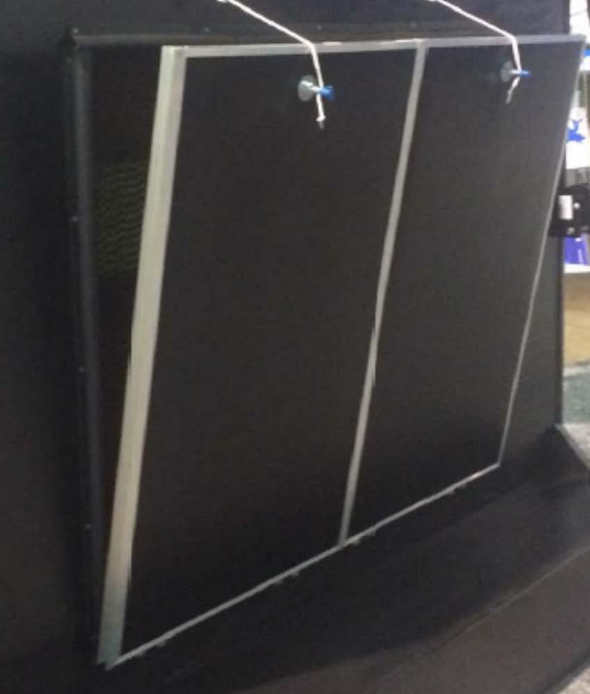
7 attachment points of individual door control cords and for this reason should be installed at the end of cabling the doors. For this reason, Control Rod eyehooks should be positioned after Nylon Rope attachment points have been established. The best position for these eyehooks is 2-3 from the Nylon Rope attachment point toward Control Machine. Figure 8 Attachment of Individual Nylon Ropes to Control Rod Each door panel has either one or two split bolts. Nylon cords coming from the split bolts of the same panel should attach to the Control Rod at the same point. This attachment point is defined as 4 plus the height of door from the closet split bolt toward control machine (See Figure 9). For Example: on a 4 (48 ) tall door, the attachment point would be 52 from the closet split bolt. Figure 9 7
 cords attached at a single point on the control rod.")
 Figure 10 The attachment of the Nylon cords to the Control Rod is made with a 3/16 Cable Clamp.")
8 In the case of 60 (5 foot) tall doors where each panel is 48 (4 feet) wide; two panels are to be treated as one for cord attachment to Control Rod. This means there will be a total of four (4) cords attached at a single point on the control rod. Position of this attachment point is the same as for the 48 high door which is 4 plus the height of the door from the closet split bolt toward the control machine (i.e. 64 ). (See Figure 10) Figure 10 The attachment of the Nylon cords to the Control Rod is made with a 3/16 Cable Clamp. Nylon cords are slipped through the clamp, knotted and clamp is tightened on Control Rod. Nylon Cord can also be tied directly to Control Rod behind the cable clamp (toward Actuation Machine) if desired. Orient cable clamp such that the Control Rod is towards Nut side of clamp (See Figure 11). It is important to get clamps tight as they supporting the weight of the Tunnel Door. Cord is run through 3/4 pulley and attached to split bolt and tighten with the 3/16 plastic nut. Tie a loop in excess cord to help with cord tension adjustment. (See Figure 12) Make sure that Nylon rope creates a straight line and is not looped over or around the Control Rod. Attach the rest of the Nylon cords throughout the entire Tunnel Door System in the same manner. Again, it is important for the Control Rod guide cup hooks to be positioned just past the connection point of the Individual Nylon Ropes as not to interfere with door actuation. Once satisfied that positioning is correct, hook loops should be closed. Figure 11 Figure 12 8
 attachment point to Control Rod. This would be less than 52 for four (4) foot tall doors and 64 for five (5) foot tall doors.")
 for a sample of double-back pulley.")
9 Special Note for Doors that are positioned close to house end Walls (Less than desired travel distance) In some cases, the Tunnel Doors may be positioned too close to house end wall prohibiting the minimum distance required for end door(s) attachment point to Control Rod. This would be less than 52 for four (4) foot tall doors and 64 for five (5) foot tall doors. This will require a pull double-back to be used to gain sufficient travel of control cords. The number of double-backs required will be contingent on door height (width) and proximity to end wall. This is not an uncommon situation and used frequently in curtain applications. See (Figure 13) for a sample of double-back pulley. Figure 13 Tunnel Door Adjustment With the control machine and winch both set to the Closed position and the control machine limits adjusted; starting in the middle of the Tunnel Door, adjust each individual Nylon Rope so the maximum P-Seal compression is about ¼. Each individual Nylon Rope should be adjusted in a similar manner moving away from center of door doing one side and then the other. Any more compression than ¼ will not improve seal and only put additional stress on Tunnel Door components. Manually open door with the control machine until opening from wall to top edge of door is 45 for 5 doors and 35 for 4 doors (See Figure 14). The control machine s Open set point should be adjusted to this point. Figure 14 9
.")
10 Safety Cable Attachment Manually open Tunnel Door System about 12 to 18. Attach a Cup Hook at four points under the top of the door opening as not to interfere with the door closing opposite the Eye Bolts assembled in door brackets (See Figure 15). Assemble 1/8 Galvanized Cable looped with cable clamp to each Eye Bolt. Note: cable should be 60 long. Figure 15 Using control machine, open door to max opening previously set. Attach other end of 1/8 Safety Cable to Eye Bolts with cable clamp allowing about 1 slack. Final Adjustment Manually open and close Tunnel Door System several times and check for proper function and any binding. This also allows the Nylon ropes to stretch and system to seat together. Close the Tunnel Door System and recheck the P-Seal compression. Make any adjustments necessary to get proper compression of P-Seal. Pay special attention to the top corners of the door system as these are areas prone to leakage. 10
11 Hog Slat Limited Warranty Hog Slat warrants products to be free from defects in material or workmanship for a period of twenty-four (24) months from the date of original purchase. Hog Slat will credit, repair, or replace, at its option any product deemed defective within this time period. Labor costs associated with the replacement or repair of the product are not covered by the Seller/Manufacturer. Conditions and Limitations 1. The product must be installed by and operated in accordance with the instructions published by the Seller/Manufacturer or Warranty will be void. 2. Warranty is void if all components are not original equipment supplied by the Seller/Manufacturer. 3. This product must be purchased from and installed by an authorized retailer/distributor or certified representative thereof or the Warranty will be void. 4. Malfunctions or failure resulting from misuse, abuse, negligence, alteration, accident, or lack of proper maintenance shall not be considered defects under the Warranty. 5. This Warranty applies only to components/systems for the care of poultry and livestock. Other applications in industry or commerce are not covered by this Warranty. 6. This Warranty applies only to the Original Purchaser of the product. The Seller/Manufacturer shall not be liable for any Consequential or Special Damage which any purchaser may suffer or claim to suffer as a result of any defect in the product. Consequential or Special Damages as used herein include, but are not limited to, lost or damaged products or goods, costs of transportation, lost sales, lost orders, lost income, increased overhead, labor and incidental costs and operational inefficiencies. THIS WARRANTY CONSTITUTES THE SELLER/MANUFACTURER S ENTIRE AND SOLE WARRANTY AND THIS MANUFACTURER EXPRESSLY DISCLAIMS ANY AND ALL OTHER WARRANTIES, INCLUDING, BUT NOT LIMITED TO, EXPRESS AND IMPLIED WARRANTIES AS TO MERCHANTABILITY, FITNESS FOR PARTICULAR PURPOSES SOLD AND DESCRIPTION OR QUALITY OF THE PRODUCT FURNISHED HEREUNDER. Hog Slat Retailers/Distributors are not authorized to modify or extend the terms and conditions of this Warranty in any manner or to offer or grant any other warranties for Hog Slat products in addition to those terms expressly stated above. An officer of Hog Slat must authorize any exceptions to this Warranty in writing. The Seller/Manufacturer reserves the right to change models and specifications at any time without notice or obligation to improve previous models. 11


")

12 This equipment must be installed in accordance with all State and Local Codes and applicable Regulations which should be followed in all cases. Authorities having jurisdiction should be consulted before installations are made. Hog Slat, Inc. PO Box 300 Newton Grove, NC Phone: (910) Fax: (910) Copyright 2015 by Hog Slat, Inc. Part Number: HSMANUAL-003 REV A3 HSART-009 Market Poultry 12
Tunnel Door Installation & Operator s Instruction Manual
 Tunnel Door Installation & Operator s Instruction Manual March 006 MV89A Chore-Time Warranty Tunnel Door Chore-Time Warranty Chore-Time Equipment ( Chore-Time ) warrants each new Chore-Time product manufactured
Tunnel Door (White) Installation & Operator s Instruction Manual
 Installation & Operator s Instruction Manual") Tunnel Door (White) Installation & Operator s Instruction Manual October 009 MV89C Chore-Time Warranty Tunnel Door (White) Chore-Time Warranty Chore-Time Equipment ( Chore-Time ) warrants each new Chore-Time
Tunnel Door (White) Installation & Operator s Instruction Manual October 009 MV89C Chore-Time Warranty Tunnel Door (White) Chore-Time Warranty Chore-Time Equipment ( Chore-Time ) warrants each new Chore-Time
Single-Sliding Header Mount INSTALLATION INSTRUCTIONS
 1-800-701-4782 Single-Sliding Header Mount INSTALLATION INSTRUCTIONS GATEWAY SO# OPENING SIZE: W x H PULLEY SYSTEM: YES / NO Upon receiving your Gateway Door, inspect packaging and contents for freight
RITE-HITE RAINGUARD TM
 RITE-HITE RAINGUARD TM RG-3000 Trailer Top Seal Installation Instructions & Owner s Manual Date of Installation: This Manual Covers All Units Shipped 8/04 to Date PRINTED IN U.S.A. PUBLICATION NO. RG30-0010
RITE-HITE TPC. FOAM DOCK SEAL WITH HEAD CURTAIN Installation Instructions & Owner s Manual. Date of Installation:
 RITE-HITE TPC FOAM DOCK SEAL WITH HEAD CURTAIN Installation Instructions & Owner s Manual Date of Installation: This Manual Covers All Units Shipped 4/08 to Date PRINTED IN U.S.A. PUBLICATION TPC00001
PATRIOT DOCKS ASSEMBLY INSTRUCTIONS
 6/1/2008 PATRIOT DOCKS ASSEMBLY INSTRUCTIONS Congratulations on your new Patriot Dock purchase. This manual contains instructions to assemble basic dock configurations for use at typical shoreline application.
OWNER S MANUAL STORAGE SHED MODELS: STOR-96-G-W-1RH & STOR-912-G-W-1RH
 STORAGE SHED MODELS: STOR-96-G-W-1RH & STOR-912-G-W-1RH OWNER S MANUAL Introduction.. 1 Assembly Instructions STOR-96-G-W-1RH... 2 Assembly Instructions STOR-912-G-W-1RH... 8 STOR-96-G-W-1RH Exploded Parts
Chapter 23. Garage Construction
 Chapter 23. Garage Construction 23.1 ESTABLISHING CHALK LINES 23.2 MEASURING AND CUTTING WALL PLATES 23.3 MARKING WINDOW & DOOR LOCATIONS ON EXTERIOR WALL PLATES 23.4 MARKING STUDS ON EXTERIOR WALL PLATES
INS A KSCR INSTALLATION INSTRUCTIONS STANDARD PROCEDURE. 1. Unpacking the KSCR Splicing the KSCR (If Required)...
...") INS-88.500-0A KSCR INSTALLATION INSTRUCTIONS STANDARD PROCEDURE 1. Unpacking the KSCR... 2 2. Splicing the KSCR (If Required)... 4 3. Assemble Curb and Rail Corners... 5 4. Install Cross Bracing (If Required)...
INS-88.500-0A KSCR INSTALLATION INSTRUCTIONS STANDARD PROCEDURE 1. Unpacking the KSCR... 2 2. Splicing the KSCR (If Required)... 4 3. Assemble Curb and Rail Corners... 5 4. Install Cross Bracing (If Required)...
Installation Manual Roof Zone Ladder Rack
 Installation Manual Roof Zone Ladder Rack 102113,E1346 Installation Time: About 90 minutes. Depending on truck and Do-it-Yourself experience level Tools Required: Electric Drill with 1/2 Chuck 1/2 & 7/32
Page 1 of 18. SunRail System Installation Instructions
 Page 1 of 18 SunRail System Installation Instructions Page 2 of 18 SunRail Stainless Steel Railing Installation Guide Table of Contents Before You Begin 3 Installing Surface Mount Bases for a Two Rail
INSTALLATION INSTRUCTIONS
 CREATING POSITIVE CUSTOMER EXPERIENCES INSTALLATION INSTRUCTIONS Universal Low Profile Tilt Mount for 42 to 63 Flat Panels NORTH AMERICA 3130 East Miraloma Avenue Anaheim, CA 92806 USA USA and Canada Phone:
Owner s Manual & Safety Instructions
 Owner s Manual & Safety Instructions Save This Manual Keep this manual for the safety warnings and precautions, assembly, operating, inspection, maintenance and cleaning procedures. Write the product s
Hardware Box 1 1/4 Diameter x 3/4 Long Bolts 24 1/4 Nylon Lock Nut 24 1/4 Diameter x 3 Long Lag Bolt 8 1/4 Washers 56
 Warning: Excessive weight hazard! Use two or more people to move, assemble or install overhead rack to avoid back or other injury. Do not leave children unattended near overhead rack. High risk of injury
Assembly Instructions
 Thank You For Purchasing The Best Overhead Storage Rack Assembly Instructions Overhead Storage Rack 8 x 4 8 x 3 8 x 2 6 x 4 6 x 3 6 x 2 4 x 4 Two 8 x4 Racks Pictured P.O. Box 714, El Cerrito, CA 94530
Office Installation Guidelines
 UH Structures Inc. dba Ebtech Industrial 2241 Industrial Drive Connellsville, PA 15425-6181 Telephone: 724-628-6100 Fax: 1-412-774-2429 www.ebtechindustrial.com Office Installation Guidelines INTRODUCTION
Sonoma Outdoor Kitchen Pergola. Assembly Instructions
 Sonoma Outdoor Kitchen Pergola Assembly Instructions Introduction Thank you for your purchase from The Outdoor GreatRoom Company. This pergola has been engineered and manufactured in the USA. This user
Tilting Flat Panel Wall Mount Installation Guide
 Tilting Flat Panel Wall Mount Installation Guide Model: A580TM Easy installation Built-in level for easy positioning Safety bolts lock the TV on the mount Easy to adjust tilt angles: +5 to -15 degrees
SS/SW3230RTA Assembly Instructions Ready to Assemble Multimedia Lectern
 650 Anthony Trail, Suite D, Northbrook, IL 60062 Phone: (800)267-5486 Fax: (800)267-5489 www.ampli.com - info@ampli.com SS/SW3230RTA Assembly Instructions Ready to Assemble Multimedia Lectern Thank you
340 & 350 SERIES DELUXE FRAMELESS BYPASS
 BATH ENCLOSURES An Alcoa Company Tel: 800-643-1514 Fax: 870-234-3181 www.alumaxbath.com INSTALLATION INSTRUCTIONS 340 & 350 SERIES DELUXE FRAMELESS BYPASS BATH ENCLOSURES Copyright Alumax Bath Enclosures
MFJ-1835K34 40,30 METER ADD ON KIT FOR THE MFJ-1835 COBWEB ANTENNA INSTRUCTION MANUAL. CAUTION: Read All Instructions Before Operating Equipment
 MFJ-1835K34 40,30 METER ADD ON KIT FOR THE MFJ-1835 COBWEB ANTENNA INSTRUCTION MANUAL CAUTION: Read All Instructions Before Operating Equipment 300 Industrial Park Road Starkville, MS 39759 USA Tel: 662-323-5869
P4263TP. Installation Guide. Low-Profile Tilting Portrait Mount for Flat-Panels
 Low-Profile Tilting Portrait Mount for Flat-Panels 1321 S. State College Blvd., Fullerton, CA 92831 USA Weight Limit Maximum Flat Panel Weight: 175 lbs. Warning Statements THE WALL STRUCTURE MUST BE CAPABLE
Unirac Flat Flashing INSTALLATION MANUAL
 Unirac Flat Flashing INSTALLATION MANUAL 2011 by Unirac, Inc. All rights reserved. Pub 110301-1ii, March 2011 A HILTI GROUP COMPANY R 1411 Broadway Boulevard NE Albuquerque, NM 87102-1545 USA IMPORTANT!
GearBoss AirPro Locker
 Installation and Owner s Instructions GearBoss AirPro Locker Wall Installation Island Installation Contents Important User Information...........................2 General...2 Manufacturer...2 Intended
Desk/Wall-Mount Rack
 Desk/Wall-Mount Rack Patent(s) Pending Installation Instructions Post P/N: 119-1752 119-1781 119-1782 119-4014 Frame P/N: 119-1591 119-1754 119-1755 Kit Contents (2) Frames (4) Posts Assembly Hardware
RITE-HITE ECLIPSE Model 620G Dock Shelter Installation Instructions & Owner s Manual
 RITE-HITE ECLIPSE Model 620G Dock Shelter Installation Instructions & Owner s Manual This Manual Covers All Units Shipped 12/13 to Date PRINTED IN U.S.A. PUBLICATION AMEN00046 39500129 2017-01-04 TABLE
ECM Installation Guide Installationsanleitung, Guía de Instalacíon, Guida de Installazione, Guide d Installation, Installatie gids
 Elliptical Ceiling Mount for 37 to 63 Flat Panels Model: ECM-3000 Warranty, Garantie, Garantía, Garanzia, Garantie, Waarborg: http://www.mounts.com/warranty 9531-000-001-0X Rev.0 www.mounts.com North America
340 & 350 SERIES BATH ENCLOSURES
 INSTALLATION INSTRUCTIONS 340 & 350 SERIES BATH ENCLOSURES 800-643-1514 www.alumaxbath.com Copyright Alumax Bath Enclosures 2010. All rights reserved. LIMITED WARRANTY AND REMEDY ALUMAX BATH ENCLOSURES
INSTALLATION INSTRUCTIONS
 INSTALLATION INSTRUCTIONS P4263F Universal Low Profi le Flat Mount for 42 to 63 Flat Panels NORTH AMERICA 3130 East Miraloma Avenue Anaheim, CA 92806 USA USA and Canada Phone: 1.800.368.9700 Fax: 1.800.832.4888
AM95 Installation Guide
 1321 S. State College Blvd., Fullerton, CA 92831 USA Included Components: Maximum Flat Panel Weight: 95 lb. / 43.1 kg. M4 X 25mm M5 X 25mm M6 X 12mm (Qty 2) M6 X 25mm M8 X 25mm Allen Key Plastic Cover
SawStop. T-GlideTM. Fence System- Professional Series II OWNER S MANUAL
 SawStop T-GlideTM Fence System- Professional Series II OWNER S MANUAL Warranty SawStop warrants to the original retail purchaser of a new T-Glide Fence System - Professional Series II from an authorized
Tilting & Swiveling Plasma/LCD Flat Panel Wall Mount Installation Guide Model: A380SM
 Tilting & Swiveling Plasma/LCD Flat Panel Wall Mount Installation Guide Model: A380SM Easy installation Built-in level for easy positioning Corrective leveling adjustments after installation Forward /
OWNER'S MANUAL TIE ROD, WALL & FLOOR MOUNTED JIBS. Model JIB-HC, JIB-LC, JIB-FM
 Vestil Manufacturing Company 999 N. Wayne Street, P.O. Box 507 Angola, IN 6703 USA Phone (60) 665-7586 Fax (60) 665-339 sales@vestil.com www.vestil.com Revised 09-0 A company dedicated to solving ergonomic
VAN STORAGE SOLUTIONS FOR THE WAY YOU WORK
 WWW.WEATHERGUARD.COM VAN STORAGE SOLUTIONS FOR THE WAY YOU WORK Weather Guard / KNAACK 420 E. Terra Cotta Ave. Crystal Lake, IL 60014 USA 800-456-7865 (Toll Free) 800-334-2981 (Fax) Knaack.OrderEntry@wernerco,.com
GB-AVSTOR5 Ceiling Equipment Storage Box with Pipe Coupler
 Ceiling Equipment Storage Box with Pipe Coupler INSTALLATION INSTRUCTIONS CREATING POSITIVE CUSTOMER EXPERIENCES 9534-500-021-00 Contents Weight Limit... 2 Warning Statements... 2 Installation Tools...
INS A KSR INSTALLATION INSTRUCTIONS STANDARD PROCEDURE. 1. Verify Curb Installation Required Installation Tools...
 INS-88.300-0A KSR INSTALLATION INSTRUCTIONS STANDARD PROCEDURE 1. Verify Curb Installation... 2 2. Required Installation Tools... 2 3. Unpacking the KSR... 3 4. Attach KSR Bottom Rail to Curb... 5 5. Attach
Specifications. Important Safety Information
 Specifications Tire Rim Capacity 4 to 12 Rim Height 16 (2) Bead Breaker Handles 21 Long Includes Aluminum Centering Cone (2) Nylon Spacers Important Safety Information 1. Do not exceed max. tire capacity.
ALUMA-VENT AWNING REGULAR END STYLE INSTALLATION INSTRUCTIONS
 ALUMA-VENT AWNING REGULAR END STYLE INSTALLATION INSTRUCTIONS Contact us at: 1-888-442-2928 or www.americana.com Options in your kit: A. Splice Pg 16 B. Column Pg 17 C. C-Channel Brace Pg 19 D. Runner
SolarMount-I INSTALLATION MANUAL
 SolarMount-I INSTALLATION MANUAL 2010 by Unirac, Inc. All rights reserved. Pub 100621-1ii, June 2010 R A HILTI GROUP COMPANY 1411 Broadway Boulevard NE Albuquerque, NM 87102-1545 USA IMPORTANT! Unirac
ALL SEASON PATIO COVER
 ALL SEASON PATIO COVER 61 Where the All Season Patio Cover is to be attached to the home, create a level line showing where the top of the mounting rail is to be located. Install each section with the
INSTALLATION GUIDE CABINETRY
 INSTALLATION GUIDE CABINETRY The instructions given here serve as general guidelines on how to install full-access cabinets in a reasonably simple installation. Many cabinet designs and installations may
Installation Instructions Tailgate Rack Bracket
 Installation Instructions Tailgate Rack Application: Jeep Wrangler 1986 Current Part Number: 41411 www.bestop.com - We re here to help! Visit our web site and click on Ask a Question. Click here for more
orientation Conergy SunTop Instructions for professional installation
 On-roof Framed modules Portrait orientation Landscape Three-tab Shingle Plain tile Slate Double Roman tile Metal roof Material warranty orientation Conergy SunTop Instructions for professional installation
1. Layout. Step 1. Step 2. Step 3. Fig. 1
 1-3/8 Panel Clamp Tools You Will Need: Tape Measure, Mason s String, Stakes, Hole Digger, Shovel, Level, Wheelbarrow, Wrenches or Adjustable Wrench, Hacksaw, Pliers, Cutting Pliers, Fence Stretcher and
INSTALLATION INSTRUCTIONS
 INSTALLATION INSTRUCTIONS Universal Low Profile Tilt Mount Model: U.S. Toll Free: 1-866-752-6271 Outside N. America: 1-503-748-5799 E-mail: ts@planar.com FRANCE Phone: +33 5 6378 3810 E-mail: emeats@planar.com
Series 1600 WeatherGuard Dock Enclosure
 Fairborn USA Inc. 205 Broadview Street Upper Sandusky, OH 43351 1-800-262-1188 Fax 1-419-294-4980 Series 1600 WeatherGuard Dock Enclosure All Models! WARNING Do not install this product unless you read
GrowSpan Round Cold Frames
 GrowSpan Round Cold Frames Photo may show a different but similar model. 2016 Growers Supply All Rights Reserved. Reproduction is prohibited without permission. STK# DIMENSIONS 103099 12' W x 8' H x 24'
00108/00110 INSTRUCTION MANUAL
 00108/00110 INSTRUCTION MANUAL Removable and Adjustable Mudflap System IMPORTANT! Please Read this Instruction Booklet prior to assembly of your Rock Tamer Kit. IMPORTANT! Exhaust Systems Note: Any modifications
Access Hatch. Installation Instructions and Operators Manual. PS DOORS Contact Information. Model AH-710 Standard High Neck Radius Cut
 Access Hatch Installation Instructions and Operators Manual Standard Low Profile Frame Model AH-710 Standard High Neck Radius Cut High Neck Frame for special applications. Table of Contents Warranty Information...2
INSTALLATION INSTRUCTIONS
 INSTALLATION INSTRUCTIONS Universal Low Profile Flat Mount Model: U.S. Toll Free: 1-866-752-6271 Outside N. America: 1-503-748-5799 E-mail: ts@planar.com FRANCE Phone: +33 5 6378 3810 E-mail: emeats@planar.com
Lodge II Pergola. Manual and Installation Instructions. Please read these instructions before removing parts from crate
 Lodge II Pergola Manual and Installation Instructions Please read these instructions before removing parts from crate Introduction Thank you for your purchase from The Outdoor GreatRoom Company. This pergola
Installation Instructions Hinged Roof Rack
 Installation Instructions Hinged Roof Rack Application: Jeep Wrangler Unlimited 2004 - Current Part Number: 41435-01 www.bestop.com - We re here to help! Visit our web site and click on Ask a Question
Assembly & Installation Instructions
 Wall Mount Garden Hose Reel Model 1041 Assembly & Installation Instructions 1 2 3 4 5 6 8 9 10 12 15 7 11 10 16 17 13 14 CONTENTS QUESTIONS? PROBLEMS? Please DO NOT contact or return this item to the retailer.
INSTRUCTION MANUAL. Model 18AVQII Five Band Vertical Antenna 10, 15, 20, 40, 80 Meter. General Description. Theory of Operation
 Model 18AVQII Five Band Vertical Antenna 10, 15, 20, 40, 80 Meter 308 Industrial Park Road Starkville, MS 39759 (662) 323-9538 Fax: (662) 323-5803 INSTRUCTION MANUAL General Description The Hy-Gain 18AVQII
Powered by. For further installation assistance: prxperformance.com/pages/murphy-rack
 Powered by The 90 Fold-in Murphy Rack is made by the creators of the original Profile Folding Rack at PRx Performance and is Patent Pending. An up-to-date record of patents and patent pending items can
Top Mount. See Installation 2 on page 2
 INSTALLATION INSTRUCTIONS TOILET SEAT Thank you for selecting American Standard the benchmark of fine quality for over 00 years. To ensure this product is installed properly, please read these instructions
RESIDENTIAL GARAGE DOOR INSTALLATION INSTRUCTIONS UNITED
 RESIDENTIAL GARAGE DOOR INSTALLATION INSTRUCTIONS UNITED THIS GENERAL INSTRUCTION MANUAL IS INTENDED FOR THE INSTALLATION OF RESIDENTIAL GARAGE DOORS AND GENERAL INFORMATION FOR COMMERCIAL DOORS. DOORS
VYTEX PREMIUM SLIDING GLASS DOOR. Table of Contents. Precautions and Safety 2. Tools Required...3. Inspect and Prepare Door...4
 VYTEX PREMIUM SLIDING GLASS DOOR Table of Contents Precautions and Safety 2 Tools Required...3 Inspect and Prepare Door...4 Hardware and Parts Check List....4 Master Frame Assembly 5 Master Frame Installation..7
Model DB Disc Caliper Brake AIR CHAMP PRODUCTS. User Manual. (i) MTY (81)
 MTY (81)") DIST. AUTORIZADO MEX (55) 53 63 3 3 QRO (44) 95 7 60 MTY (8) 83 54 0 8 AIR CHAMP PRODUCTS User Manual Model DB Disc Caliper Brake (i) FORM NO. L-00-G-030 MEX (55) 53 63 3 3 MTY (8) 83 54 0 8 DIST. AUTORIZADO
DIST. AUTORIZADO MEX (55) 53 63 3 3 QRO (44) 95 7 60 MTY (8) 83 54 0 8 AIR CHAMP PRODUCTS User Manual Model DB Disc Caliper Brake (i) FORM NO. L-00-G-030 MEX (55) 53 63 3 3 MTY (8) 83 54 0 8 DIST. AUTORIZADO
PRIMO 56" FOOSBALL TABLE ASSEMBLY INSTRUCTIONS
 PRIMO 56" FOOSBALL TABLE ASSEMBLY INSTRUCTIONS NG1035 THANK YOU! Thank you for purchasing this product. We work around the clock and around the globe to ensure that our products maintain the highest possible
Deck Mount Installation with Bench
 Deck Mount Installation with Bench 1. Mark track with square. 2. Cut tracks with saw. 3. Drill ¼ hole (if needed.) 4. Countersink track. 5. Countersink all track 6. File all track ends. ends. 7. Lay out
Installation Instructions Lower Cargo Rack Bracket
 Installation Instructions Lower Cargo Rack Application: Jeep Wrangler 2003 Current Part Number: 41437 US Patent 6799706 www.bestop.com - We re here to help! Visit our web site and click on Ask a Question.
SERIES M MIXER MASTS
 SERIES M MIXER MASTS T AB L E O F C O N T E N T S V e n d o r D a t a Material Data Sheet 4-in. Mixer Mast Specification 3-in. Mixer Mast Specification 2 - in. M i x e r M a s t S p e c i f i c a t i o
Box Edge Plus Steel Shelving Installation Instructions
 Box Edge Plus Steel Shelving Installation Instructions IMPORTANT PRODUCT LIABILITY INFORMATION Read all instructions before proceeding with installation or shelf loading. Vital product information pertaining
Worktop INDEX eight Capacity Unpacking
 Pro.0 Series Warning: Excessive weight hazard! Use two or more people to move, assemble or install cabinets and locker to avoid back injury. Do not leave children unattended near cabinets. High risk of
Owner s Manual LSP38 38 Lawn Sweeper
 Owner s Manual LSP38 38 Lawn Sweeper Manual Contents Safety Instructions Assembly Operation Maintenance Parts Warranty 2 4-13 2 11 14-15 16 Your Lawn Sweeper Congratulations on your purchase of a new Precision
INSTALLATION INSTRUCTIONS CJ-5 M38A PART # With Doors
 INSTALLATION INSTRUCTIONS CJ-5 M38A1 1955-1975 PART #109-011 With Doors Thank you for purchasing Specialty s Convertible Top for your Jeep vehicle. It has been designed for great fit and long wear. Please
GrowSpan Series 500 Roll-Up Ends
 GrowSpan Series 500 Roll-Up Ends Photo may show a different but similar model. Doorframe materials are not included. 2016 Growers Supply All Rights Reserved. Reproduction is prohibited without permission.
OPERATORS MANUAL WEEKENDER STEEL LADDER RACK
 OPERATORS MANUAL WEEKENDER STEEL LADDER RACK WWW.WEATHERGUARD.COM MODELS 1450 & 1475 1475 Shown INSTALLATION TIME Approximate installation time: 60 minutes (depending on truck equipment installation experience
Heavy Wall Applied Stop Tube Frame and Door Installation
 INSTALLATION INSTRUCTIONS Heavy Wall Applied Stop Tube Frame and Door Installation Read all instructions before beginning installation. These instructions are provided to help prevent installation problems
GIRTS ON BACK OF BUILDING
 GIRTS ON BACK OF BUILDING ALL GIRTS ARE 1 1/2 SQUARE TUBE. GIRT LENGTHS FOR 12, 20, 24, AND 30 WIDE BUILDINGS: ON 12 WIDE BUILDINGS GIRTS ARE 67 3/4 LONG ON 20 WIDE BUILDINGS GIRTS ARE 56 3/4 LONG ON 24
Assembly Instructions 10 X 10 Aluminum Frame Building
 Assembly Instructions 10 X 10 Aluminum Frame Building 27 97 9 8 47 36 74 52 10 10 X 10 Square Building W/ Dome Includes: The Steel Entry Door with a Dead Bolt Lock assembly and Aluminum Door Frame. Metal
RPR-265. Power Rack (Cage)
") ASSEMBLY INSTRUCTIONS 3 3/4" RPR-5 50 3/4" 51 1/4" Power Rack (Cage) TuffStuff Fitness Equipment, Inc. 15 E. Franklin Avenue Pomona, CA 9166, USA Ph: 909-6-1600 Fax: 909-6-496 E-mail: service@tuffstuff.net
ASSEMBLY INSTRUCTIONS 3 3/4" RPR-5 50 3/4" 51 1/4" Power Rack (Cage) TuffStuff Fitness Equipment, Inc. 15 E. Franklin Avenue Pomona, CA 9166, USA Ph: 909-6-1600 Fax: 909-6-496 E-mail: service@tuffstuff.net
738 SERIES PIVOT SHOWER DOOR
 INSTALLATION INSTRUCTIONS 738 SERIES PIVOT SHOWER DOOR Copyright Alumax Bath Enclosures 1997. All rights reserved. Page 1 of 8 LIMITED WARRANTY AND REMEDY Alumax Bath Enclosures warrants to its dealers,
Costco High Wire Assembly Instruc ons & Owner's Manual
 2254 Costco High Wire Assembly Instruc ons & Owner's Manual Important! Read this manual completely through before assembly and use. Consumer assistance Toll free If you need to order replacement parts
INSTALLATION INSTRUCTIONS
 INSTALLATION INSTRUCTIONS Universal Short Throw Projector Arm Model: UNI-STA/UNI-EXT NORTH AMERICA 3130 East Miraloma Avenue Anaheim, CA 92806 USA USA and Canada Phone: 1-800-368-9700 Fax: 1-800-832-4888
INSTALLATION & OPERATING INSTRUCTIONS. REDCO LETTUCE KING I and LETTUCE KING IV
 INSTALLATION & OPERATING INSTRUCTIONS for REDCO LETTUCE KING I and LETTUCE KING IV Lettuce King I Shown with optional Drum Ring Lettuce King IV TO BE SERVICED ONLY BY AUTHORIZED PERSONS P/N: 2802381 REV:
Worktop. Weight Capacity. 100 lbs. 21 Corner Worktop. 48 Worktop. Fits over 2 Cabinets. 72 Worktop. Fits over 3 Cabinets. 200 lbs. 150 lbs.
 Bold.0 Warning: Excessive weight hazard! Use two or more people to move, assemble or install cabinets and locker to avoid back injury. Do not leave children unattended near cabinets. High risk of tipping
MM540 Installation Instructions IMPORTANT SAFETY INSTRUCTIONS - SAVE THESE INSTRUCTIONS
 MM50 Installation Instructions IMPORTANT SAFETY INSTRUCTIONS - SAVE THESE INSTRUCTIONS Please read this entire manual before you begin. Do not unpack any contents until you verify all requirements on PAGE.
Model 6360/6361. Ambulance Cot Fastener INSTALLATION/OPERATION INSTRUCTIONS. IMPORTANT Keep manual on file at all times.
 IMPORTANT Keep manual on file at all times. Model 6360/6361 Ambulance Cot Fastener INSTALLATION/OPERATION INSTRUCTIONS For Parts or Technical Assistance 1 800 784 4336 Table of Contents Introduction..............................................................................
FOR PROFESSIONAL GARAGE DOOR INSTALLERS
 Composite Garage Doors Installation Instructions FOR PROFESSIONAL GARAGE DOOR INSTALLERS Tools required Screwdriver Claw Hammer Locking Pliers Power Drill Level with a 3/32" Drill Bit Utility Knife 9/16",
Installation and Assembly: Articulating Swivel Arm for 37" - 60" Flat Panel Displays
 Installation and Assembly: Articulating Swivel Arm for 37" - 60" Flat Panel Displays Models: PLA60, PLA60-S, PLAV60, PLAV60-S Max UL Load Capacity: 175 lb (79 kg) 2300 White Oak Circle Aurora, Il 60502
ClearSpan Mini Grab Bag Shelters
 ClearSpan Mini Grab Bag Shelters Photo may show a different but similar model. Baseboard is not included. 2008 ClearSpan All Rights Reserved. Reproduction is prohibited without permission. STK# DIMENSIONS
FENCE INSTALLATION GUIDE 8 HIGH WALLS
 FENCE INSTALLATION GUIDE 8 HIGH WALLS 1.866.648.9336 www.simtekfence.com INSTALLATION GUIDE These instructions are designed to assist both professional installers and do-it-yourselfers of SimTek decorative
PB 8328 WS 8328 IMPORTANT!! JAMBOREE
 PB 8328 WS 8328 JAMBOREE IMPORTANT!! PLEASE READ BEFORE BEGINNING ASSEMBLY!! Please make sure all lumber, hardware and accessory parts are accounted for. If you are missing anything, please DO NOT RETURN
Instruction Sheet REB SERIES. Rotating Sliding Base REB18
 Instruction Sheet REB SERIES Rotating Sliding Base REB14 REB18 THANK YOU Thank you for purchasing the REB Series Rotating Sliding Base. Please read these instructions thoroughly before installing this
Instruction Sheet D-CPU. Secure CPU Holder
 Instruction Sheet D-CPU Secure CPU Holder I-00457 Rev A PARTS LIST NOTE: Select Security Components when a more secure application is desired. Mounting Track with Mounting Tape Security Bracket Assembly
PRE-ENGINEERED HORSE STALL SYSTEMS SDFD SLIDING DOOR c/w FOLD-DOWN GRILL. & Assembly. Installation Instructions
 PRE-ENGINEERED HORSE STALL SYSTEMS 4800 SDFD SLIDING DOOR c/w FOLD-DOWN GRILL & Assembly Installation Instructions 4800 SDFD Sliding Door c/w Fold-Down Grill Components - 1 3 /4" x 2" x 88" channels (2)
Single Flex and Double Flex Couplings (i)
") Single Flex and Double Flex Couplings (i) FORM NO. L00G00 In accordance with Nexen s established policy of constant product improvement, the specifications contained in this manual are subject to change
Single Flex and Double Flex Couplings (i) FORM NO. L00G00 In accordance with Nexen s established policy of constant product improvement, the specifications contained in this manual are subject to change
Select Lab Fixed Height Workstation
 Assembly Instructions Select Lab Fixed Height Workstation Contents Important User Information.............................. 2 Safety Precautions.................................... 3 Required Tools........................................
U.S. Rack, Inc Falcon Drive, Madera, CA APR17 INSTALLATION AND USE INSTRUCTIONS for SIDE-MOUNT LADDER RACK
 U.S. Rack, Inc. 2850 Falcon Drive, Madera, CA 93637 15APR17 INSTALLATION AND USE INSTRUCTIONS for SIDE-MOUNT LADDER RACK WARNING: Do NOT attempt to install or use this rack without following all instructions.
LJ element beam for 10 or 12 meters INSTRUCTION MANUAL. CAUTION: Read All Instructions Before Operating Equipment
 LJ-113 3 element beam for 10 or 1 meters INSTRUCTION MANUAL CAUTION: Read All Instructions Before Operating Equipment 308 Industrial Park Road Starkville, MS 39759 USA Tel: 66-33-9538 Fax: 66-33-6551 VERSION
Tilting, Swiveling & Rotating Flat Panel Wall Mount
 Tilting, Swiveling & Rotating Flat Panel Wall Mount Model: VXA980TC +5 to -5 +5 to -5 Supports most 0-80 Flat Panel TVs Maximum Weight Capacity: 32 lbs. Supports VESA Sizes up to 600x500 For technical
F-150 Structural Holding System
 F-150 Structural Holding System Users Manual December 2013 by Vehicle Service Group. All rights reserved. CO8812.2 502073 Rev. - 12/11/2013 CHIEF'S LIMITED ONE-YEAR WARRANTY & LIABILITY Chief Automotive
Sliding Door Kit
 YOU MUST READ THIS DOCUMENT BEFORE YOU BEGIN TO ASSEMBLE THE DOOR KIT. Thank you for purchasing this GrowSpan door kit. When properly assembled and maintained, this product will provide years of reliable
Assembly & Installation Instructions
 Wall Mount Hose Reel Model 04-GH Configuration Pulls the hose out straight away from the wall. Configuration Pulls the hose out along side the wall. Assembly & Installation Instructions Version 0409 A
Installation Instructions Hard Top Part # , Wrangler 2 & 4 Door
 Please read instructions entirely before installing this product. This accessory is designed and manufactured primarily to augment the vehicles appearance and to protect the occupants from normal weather
Installation Instructions SRC OFF ROAD ROOF RACK Wrangler,97-06 Wrangler,04-06 Unlimited Part # s 76711,76713,76715)
") NOTE: Please read this information entirely before installing. To obtain correct installation, we recommend you follow these step-by-step instructions carefully. Please take care when installing this product
NOTE: Please read this information entirely before installing. To obtain correct installation, we recommend you follow these step-by-step instructions carefully. Please take care when installing this product
INSTALLATION INSTRUCTIONS
 INSTALLATION INSTRUCTIONS CTM-MS1 Flat Panel Display Mount (26 to 37 ) NORTH AMERICA 3130 East Miraloma Avenue Anaheim, CA 92806 USA USA and Canada Phone: 800-368-9700 Fax: 800-832-4888 Other Locations
AM500-U Installation Guide
 1321 S. State College Blvd., Fullerton, CA 92831 USA Included Components Maximum Flat Panel Weight: 500 lb. / 226.79 kg. Wall Mount Bracket (Qty 2) Cross Bar 5/16 Flat Washers (Qty 6) Universal Spacers