Lecture 3: Logic circuit. Combinational circuit and sequential circuit
|
|
|
- Arlene Fleming
- 5 years ago
- Views:
Transcription
1 Lecture 3: Logic circuit Combinational circuit and sequential circuit TRAN THI HONG
2 Content Lecture : Computer organization and performance evaluation metrics Lecture 2: Processor architecture and memory system Lecture 3: Logic circuit: Combinational circuit and sequential circuit Lecture 4: Number system and Its Importance Lecture 5: Hardware design by HDL Lecture 6: Parallel programming Lecture 7: Hardware design by high-level synthesis Lecture 8: Computer system design and its applications 2
3 Lecture Information 3
4 Grading ( 評価 ) Mini-test (4%) Score is based on the number of times that you attend the class and your enthusiastic on doing mini-test. You may get MAX score although your answer is not correct! If you cannot attend the lecture with reasonable reason (ex: attend conference), you can get MAX score if you: Inform about your absent to me via hong@is.naist.jp Study from lecture video and submit mini-test by next time. Home-work: (6%) Score is based on the correction of your home-work Bonus (+%) Your activeness, enthusiastic during the lecture (make question, answer the question, etc.) 4
5 Basic Logic Circuits Basic Logic Gates: Not, And, Or, Xor, Xnor, etc. Combinational Circuits Arithmetic Operator: adder, multiplier, etc. Encoder Multiplexer Comparators Sequential Circuits Memory Elements: Latch, FlipFlop, Register, etc. Sequential Circuits 5
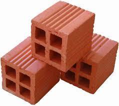


6 brick 6


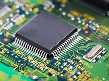
7 Transistor 7


8 Overview of Hardware Circuit Design System Block Block 2 Block N Hardware System Verilog HDL Adder Register Memory Comb. Circuit: Do specific function. Adder Mul. Seq. Circuit: Register, memory, etc. Latch Flipflop Digital Circuit Design MUX Comp. Binary Logic gate: Not, And, Or, etc. Comparator Analog Circuit Design Transistors 8
 Junction gate FET (JFET) Metal-Oxide Semiconductor (MOS) MOSFET")
9 Transistor There are several types of transistor such as: Bipolar junction transistor (BJT) Field-Effect Transistor (FET) Junction gate FET (JFET) Metal-Oxide Semiconductor (MOS) MOSFET 9

10 Basic Logic Gates NOT Gate Logic gates are the element building blocks of a digital circuit. Basic element of logic gate is transistor NOT gate is built from 2 MOS transistors Symbol True-Table Circuit
11 Basic Logic Gates NOR Gate NOR gate is built from 4 transistors: 2 p-type in serial and 2 n-type in parallel Symbol True-Table Circuit


12 Basic Logic Gates OR Gate OR gate is built by adding a NOT gate into NOR gate Symbol NOR Circuit NOT True-Table 2
13 NAND gate is built from 4 transistors: 2 p-type in parallel & 2 n-type in serial Symbol Basic Logic Gates NAND Gate True-Table Circuit 3

14 Basic Logic Gates AND Gate Circuit Symbol True-Table NAND NOT 4


15 Basic Logic Gates XOR Gate Symbol Circuit True-Table 5


16 Basic Logic Gates XNOR Gate Symbol Circuit True-Table 6
17 Minitest-3. How many p-type, n-type CMOS transistors are needed for building: NAND gate OR gate XOR gate XNOR gate 7
18 Minitest-3.: Answer How many p-type, n-type CMOS transistors are needed for building: NAND gate: 2 p-type + 2 n-type CMOS transistors OR gate: 3 p-type + 3 n-type CMOS transistors XOR gate: 4 NOT + 2 NAND + OR = 4 (p + n) + 2 (2p + 2n) + (3p + 3n) = p-type + n-type transistors XNOR gate: p-type + n-type transistors 8
19 Basic Logic Circuits Basic Logic Gates: Not, And, Or, Xor, Xnor, etc. Combinational Circuits Arithmetic Operator: adder, multiplier, etc. Encoder Multiplexer Comparators Sequential Circuits Memory Elements: Latch, FlipFlop, Register, etc. Sequential Circuits 9
20 Combinational Circuits - Arithmetic Circuits - (/4) Basic operator: adder Subtractor is the adder of negative number. Multiplier is the sum of multiple adders Divider is very complex and rarely used in hardware design. Half Adder 2
21 Combinational Circuits - Arithmetic Circuits - (2/4) Full Adder Input Output 2
 + (6) (3) A B A B A2 B2 A3 B3 Half Adder C Full C Full C2 Adder Adder Full Adder S S S2 S3 C3")
22 Combinational Circuits - Arithmetic Circuits - (3/4) 4-bit Adder A3 A2 A A + B3 B2 B B C3 C2 C C S3 S2 S S Example: (-3) + (6) (3) A B A B A2 B2 A3 B3 Half Adder C Full C Full C2 Adder Adder Full Adder S S S2 S3 C3 22
 Multiplier A2 A A B2 B B A2 A A B + A2 A A B")

23 Combinational Circuits - Arithmetic Circuits - (3/4) Multiplier A2 A A B2 B B A2 A A B + A2 A A B 2 + A2 A A B2 4 Example: (2) (5) + + () A2 B2 P4 A2 B A B2 P3 A2 B A B A B2 A B2 P2 A B A B A B P A B A B P 23
24 Other Combinational Circuits - Decoder - - An n-to-2 n decoder is a multiple output combinational logic circuit with n input and 2 n output signals. - For each possible input condition, one and only one output signal is active. LSB x x n-to2 n Decoder m m Input x x Output m 3 m 2 m m MSB x n- m B (B = 2 n -) Exercise: Design a 2-to-4 decoder 24
25 Other Combinational Circuits - Multiplexer & Demultiplexer - - Multiplexer (or MUX) selects one of many input signals to appear on a single output line - Demultiplexer (or DEMUX) takes a single input signals and routes it to one of several output signals. D D D Y Y D D n D n SEL SEL D D n Y Y MUX DEMUX D D n 25
26 Other Combinational Circuits - Comparator- - A comparator determines the relative magnitude of two binary numbers. - There are many types of comparators such as: A B A B > A Y B < Y 3 A B Y 2 A B = Y 4 Input Output Relationship Y Y 2 Y 3 Y 4 Y 5 A > B A < B A = B Y 5 26
27 Combinational Circuits Combinational circuit: used for calculation Always representing a present state No past state in the circuit A NAND gate out XOR gate out B out = AB A B out = A^B NOT gate A out out = A Out changes when A or B changes; No past, nor next info. 27
28 Combinational Circuits Combinational Circuits Always represent a current state No past state in the circuit Not possible to achieve counter Counter: 2 3 N Q: What will happen on A_plus? A + Comb. Logic A_plus A: A_plus will go w/o stop! No stable state if input is not stable. That s the reason we need sequential circuit. 28
29 Minitest-3.2????????????? = 2 b 29

30 Minitest-3.2: Answer SEL = 2 b = 2 Y = D 2 = 2 b 3
31 Basic Logic Circuits Basic Logic Gates: Not, And, Or, Xor, Xnor, etc. Combinational Circuits Arithmetic Operator: adder, multiplier, etc. Encoder Multiplexer Comparators Sequential Circuits Memory Elements: Latch, FlipFlop, Register, etc. Sequential Circuits 3
32 - Sequential circuit is a circuit that is able to REMEMBER its previous data. - Two main types: Latch Memory Elements FlipFlop Latch Controlled by excitation input signals Two types: - Set latch: force to - Reset latch: force to FlipFlop Controlled by clock signal Many Types: - Master Slave SR FlipFlop - Master Slave D FlipFlop - Master Slave JK FlipFlop - Edge-triggered D FlipFlop - Edge-triggered JK FlipFlop - T FlipFlop Device state is changed immediately Device state is changed after clock cycle 32
33 Memory Elements SR Latch Set Reset Latch Set means output Reset means output e.g. reset status The feedback loop creates stable status S R Q Q S R Q Q Q prev Q prev (stored) (reset) (set) (not used) 33
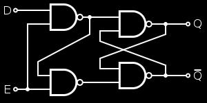
34 Memory Elements Gate D Latch E D Q Q x Q prev Q prev (stored) (reset) (set) 34
35 D Memory Elements Master/Slave D FlipFlop Accept input Keep (Locked) Q cp cp= D Keep (Locked) Accept input Q cp cp= 35
36 Memory Elements Master/Slave D FlipFlop Register Clock Data in Enable b msb... b b Data out Clock b msb... b b Write_address read_data Memory: is a bank of registers Write_data Write_enable b msb... b b read_address b msb... b b 36
37 Sequential Logic Circuits Definition: Outputs depends on stored information (current state) and current inputs Example: Bank account State = Waiting for new operation (stored value: your current balance) Input = Withdraw or deposit Output = Your new balance Combinational logic and one/or more memory elements are used in sequential logic Mem. Element input Comb. Logic output Sequential Circuit 37
38 Sequential Logic Circuits Mem. Element input Comb. Logic output Sequential Circuit Memory element Provide a lock of current status Combinational logic Calculate new status 38
39 Modeling the Circuit Looking into the memory It stores n-bits bit has two states, as and ; 2 bits have four states, as,,, ; n bits have 2 n states. input Mem. Element Comb. Logic output Sequential Circuit The amount of information to be stored is finite a Finite State Machine (FSM) to describe the 2 n states 39
40 Two Kinds of FSM Models Mealy Machine Outputs are function of the present/current state and the present inputs Major FSM model we use input Mem. Element Comb. Logic Moore Machine Outputs are independent of the inputs i.e. dependent on present state only output Sequential Circuit input Comb. Logic Mem. Element output Sequential Circuit 4
41 Minitest-3.3???? 4
42 Minitest-3.3: Answer???? 42
43 Summary Basic Logic Gates: Not, And, Or, Xor, Xnor, etc. Combinational Circuits Arithmetic Operator: adder, multiplier, etc. Encoder Multiplexer Comparators Sequential Circuits Memory Elements: Latch, FlipFlop, Register, etc. Sequential Circuits 43
Chapter 3 Digital Logic Structures
 Chapter 3 Digital Logic Structures Transistor: Building Block of Computers Microprocessors contain millions of transistors Intel Pentium 4 (2): 48 million IBM PowerPC 75FX (22): 38 million IBM/Apple PowerPC
Chapter 3 Digital Logic Structures
 Chapter 3 Digital Logic Structures Transistor: Building Block of Computers Microprocessors contain millions of transistors Intel Pentium 4 (2000): 48 million IBM PowerPC 750FX (2002): 38 million IBM/Apple
Combinational Logic Circuits. Combinational Logic
 Combinational Logic Circuits The outputs of Combinational Logic Circuits are only determined by the logical function of their current input state, logic 0 or logic 1, at any given instant in time. The
Unit level 4 Credit value 15. Introduction. Learning Outcomes
 Unit 20: Unit code Digital Principles T/615/1494 Unit level 4 Credit value 15 Introduction While the broad field of electronics covers many aspects, it is digital electronics which now has the greatest
CS302 - Digital Logic Design Glossary By
 CS302 - Digital Logic Design Glossary By ABEL : Advanced Boolean Expression Language; a software compiler language for SPLD programming; a type of hardware description language (HDL) Adder : A digital
Preface to Third Edition Deep Submicron Digital IC Design p. 1 Introduction p. 1 Brief History of IC Industry p. 3 Review of Digital Logic Gate
 Preface to Third Edition p. xiii Deep Submicron Digital IC Design p. 1 Introduction p. 1 Brief History of IC Industry p. 3 Review of Digital Logic Gate Design p. 6 Basic Logic Functions p. 6 Implementation
ET475 Electronic Circuit Design I [Onsite]
![ET475 Electronic Circuit Design I [Onsite]](/thumbs/89/98281525.jpg "ET475 Electronic Circuit Design I [Onsite]") ET475 Electronic Circuit Design I [Onsite] Course Description: This course covers the analysis and design of electronic circuits, and includes a laboratory that utilizes computer-aided software tools for
ET475 Electronic Circuit Design I [Onsite] Course Description: This course covers the analysis and design of electronic circuits, and includes a laboratory that utilizes computer-aided software tools for
Preface... iii. Chapter 1: Diodes and Circuits... 1
 Table of Contents Preface... iii Chapter 1: Diodes and Circuits... 1 1.1 Introduction... 1 1.2 Structure of an Atom... 2 1.3 Classification of Solid Materials on the Basis of Conductivity... 2 1.4 Atomic
Chapter 3. H/w s/w interface. hardware software Vijaykumar ECE495K Lecture Notes: Chapter 3 1
 Chapter 3 hardware software H/w s/w interface Problems Algorithms Prog. Lang & Interfaces Instruction Set Architecture Microarchitecture (Organization) Circuits Devices (Transistors) Bits 29 Vijaykumar
Fan in: The number of inputs of a logic gate can handle.
 Subject Code: 17333 Model Answer Page 1/ 29 Important Instructions to examiners: 1) The answers should be examined by key words and not as word-to-word as given in the model answer scheme. 2) The model
Number system: the system used to count discrete units is called number. Decimal system: the number system that contains 10 distinguished
 Number system: the system used to count discrete units is called number system Decimal system: the number system that contains 10 distinguished symbols that is 0-9 or digits is called decimal system. As
Brought to you by. Priti Srinivas Sajja. PS01CMCA02 Course Content. Tutorial Practice Material. Acknowldgement References. Website pritisajja.
 Brought to you by Priti Srinivas Sajja PS01CMCA02 Course Content Tutorial Practice Material Acknowldgement References Website pritisajja.info Multiplexer Means many into one, also called data selector
UNIT-IV Combinational Logic
 UNIT-IV Combinational Logic Introduction: The signals are usually represented by discrete bands of analog levels in digital electronic circuits or digital electronics instead of continuous ranges represented
Combinational Circuits DC-IV (Part I) Notes
 Notes") Combinational Circuits DC-IV (Part I) Notes Digital Circuits have been classified as: (a) Combinational Circuits: In these circuits output at any instant of time depends on inputs present at that instant
Combinational Circuits DC-IV (Part I) Notes Digital Circuits have been classified as: (a) Combinational Circuits: In these circuits output at any instant of time depends on inputs present at that instant
Exam #2 EE 209: Fall 2017
 29 November 2017 Exam #2 EE 209: Fall 2017 Name: USCid: Session: Time: MW 10:30 11:50 / TH 11:00 12:20 (circle one) 1 hour 50 minutes Possible Score 1. 27 2. 28 3. 17 4. 16 5. 22 TOTAL 110 PERFECT 100
SRV ENGINEERING COLLEGE SEMBODAI RUKMANI VARATHARAJAN ENGINEERING COLLEGE SEMBODAI
 SEMBODAI RUKMANI VARATHARAJAN ENGINEERING COLLEGE SEMBODAI 6489 (Approved By AICTE,Newdelhi Affiliated To ANNA UNIVERSITY::Chennai) CS 62 DIGITAL ELECTRONICS LAB (REGULATION-23) LAB MANUAL DEPARTMENT OF
Introduction. BME208 Logic Circuits Yalçın İŞLER
 Introduction BME208 Logic Circuits Yalçın İŞLER islerya@yahoo.com http://me.islerya.com 1 Lecture Three hours a week (three credits) No other sections, please register this section Tuesday: 09:30 12:15
EE : ELECTRICAL ENGINEERING Module 8 : Analog and Digital Electronics INDEX
 Pearl Centre, S.B. Marg, Dadar (W), Mumbai 400 028. Tel. 4232 4232 EE : ELECTRICAL ENGINEERING Module 8 : Analog and Digital Electronics Contents INDEX Sub Topics 1. Characteristics of Diodes, BJT & FET
S-[F] NPW-02 June All Syllabus B.Sc. [Electronics] Ist Year Semester-I & II.doc - 1 -
![S-[F] NPW-02 June All Syllabus B.Sc. [Electronics] Ist Year Semester-I & II.doc - 1 -](/thumbs/79/79759849.jpg "S-[F] NPW-02 June All Syllabus B.Sc. [Electronics] Ist Year Semester-I & II.doc - 1 -") - 1 - - 2 - - 3 - DR. BABASAHEB AMBEDKAR MARATHWADA UNIVERSITY, AURANGABAD SYLLABUS of B.Sc. FIRST & SECOND SEMESTER [ELECTRONICS (OPTIONAL)] {Effective from June- 2013 onwards} - 4 - B.Sc. Electronics
- 1 - - 2 - - 3 - DR. BABASAHEB AMBEDKAR MARATHWADA UNIVERSITY, AURANGABAD SYLLABUS of B.Sc. FIRST & SECOND SEMESTER [ELECTRONICS (OPTIONAL)] {Effective from June- 2013 onwards} - 4 - B.Sc. Electronics
Lecture 02: Digital Logic Review
 CENG 3420 Lecture 02: Digital Logic Review Bei Yu byu@cse.cuhk.edu.hk CENG3420 L02 Digital Logic. 1 Spring 2017 Review: Major Components of a Computer CENG3420 L02 Digital Logic. 2 Spring 2017 Review:
IES Digital Mock Test
 . The circuit given below work as IES Digital Mock Test - 4 Logic A B C x y z (a) Binary to Gray code converter (c) Binary to ECESS- converter (b) Gray code to Binary converter (d) ECESS- To Gray code
ELECTRONICS WITH DISCRETE COMPONENTS
 ELECTRONICS WITH DISCRETE COMPONENTS Enrique J. Galvez Department of Physics and Astronomy Colgate University WILEY John Wiley & Sons, Inc. ^ CONTENTS Preface vii 1 The Basics 1 1.1 Foreword: Welcome to
Sr. No. Instrument Specifications. TTL (Transistor-Transistor Logic) based on bipolar junction transistors
 based on bipolar junction transistors") MIT College of Engineering, Pune. Department of Electronics & Telecommunication (Electronics Lab) EXPERIMENT NO 01 TITLE OF THE EXPERIMENT: Verify four voltage and current parameters for TTL and CMOS (IC
MIT College of Engineering, Pune. Department of Electronics & Telecommunication (Electronics Lab) EXPERIMENT NO 01 TITLE OF THE EXPERIMENT: Verify four voltage and current parameters for TTL and CMOS (IC
EC 1354-Principles of VLSI Design
 EC 1354-Principles of VLSI Design UNIT I MOS TRANSISTOR THEORY AND PROCESS TECHNOLOGY PART-A 1. What are the four generations of integrated circuits? 2. Give the advantages of IC. 3. Give the variety of
Electronics. Digital Electronics
 Electronics Digital Electronics Introduction Unlike a linear, or analogue circuit which contains signals that are constantly changing from one value to another, such as amplitude or frequency, digital
SYLLABUS of the course BASIC ELECTRONICS AND DIGITAL SIGNAL PROCESSING. Master in Computer Science, University of Bolzano-Bozen, a.y.
 SYLLABUS of the course BASIC ELECTRONICS AND DIGITAL SIGNAL PROCESSING Master in Computer Science, University of Bolzano-Bozen, a.y. 2017-2018 Lecturer: LEONARDO RICCI (last updated on November 27, 2017)
COMPUTER ORGANIZATION & ARCHITECTURE DIGITAL LOGIC CSCD211- DEPARTMENT OF COMPUTER SCIENCE, UNIVERSITY OF GHANA
 COMPUTER ORGANIZATION & ARCHITECTURE DIGITAL LOGIC LOGIC Logic is a branch of math that tries to look at problems in terms of being either true or false. It will use a set of statements to derive new true
R & D Electronics DIGITAL IC TRAINER. Model : DE-150. Feature: Object: Specification:
 DIGITAL IC TRAINER Model : DE-150 Object: To Study the Operation of Digital Logic ICs TTL and CMOS. To Study the All Gates, Flip-Flops, Counters etc. To Study the both the basic and advance digital electronics
Subtractor Logic Schematic
 Function Of Xor Gate In Parallel Adder Subtractor Logic Schematic metic functions, including half adder, half subtractor, full adder, independent logic gates to form desired circuits based on dif- by integrating
DIGITAL INTEGRATED CIRCUITS A DESIGN PERSPECTIVE 2 N D E D I T I O N
 DIGITAL INTEGRATED CIRCUITS A DESIGN PERSPECTIVE 2 N D E D I T I O N Jan M. Rabaey, Anantha Chandrakasan, and Borivoje Nikolic CONTENTS PART I: THE FABRICS Chapter 1: Introduction (32 pages) 1.1 A Historical
Digital Electronics 8. Multiplexer & Demultiplexer
 1 Module -8 Multiplexers and Demultiplexers 1 Introduction 2 Principles of Multiplexing and Demultiplexing 3 Multiplexer 3.1 Types of multiplexer 3.2 A 2 to 1 multiplexer 3.3 A 4 to 1 multiplexer 3.4 Multiplex
QUIZ. What do these bits represent?
 QUIZ What do these bits represent? 1001 0110 1 QUIZ What do these bits represent? Unsigned integer: 1101 1110 Signed integer (2 s complement): Fraction: IBM 437 character: Latin-1 character: Huffman-compressed
(CSC-3501) Lecture 6 (31 Jan 2008) Seung-Jong Park (Jay) CSC S.J. Park. Announcement
 Lecture 6 (31 Jan 2008) Seung-Jong Park (Jay) CSC S.J. Park. Announcement") Seung-Jong Park (Jay) http://www.csc.lsu.edu/~sjpark Computer Architecture (CSC-3501) Lecture 6 (31 Jan 2008) 1 Announcement 2 1 Reminder A logic circuit is composed of: Inputs Outputs Functional specification
Seung-Jong Park (Jay) http://www.csc.lsu.edu/~sjpark Computer Architecture (CSC-3501) Lecture 6 (31 Jan 2008) 1 Announcement 2 1 Reminder A logic circuit is composed of: Inputs Outputs Functional specification
0 A. Review. Lecture #16. Pipeline big-delay CL for faster clock Finite State Machines extremely useful You!ll see them again in 150, 152 & 164
 CS61C L15 Representations of Combinatorial Logic Circuits (1) inst.eecs.berkeley.edu/~cs61c CS61C : Machine Structures Lecture #16 Representations of Combinatorial Logic Circuits CPS today! 2005-10-26
LOGIC DIAGRAM: HALF ADDER TRUTH TABLE: A B CARRY SUM. 2012/ODD/III/ECE/DE/LM Page No. 1
 LOGIC DIAGRAM: HALF ADDER TRUTH TABLE: A B CARRY SUM K-Map for SUM: K-Map for CARRY: SUM = A B + AB CARRY = AB 22/ODD/III/ECE/DE/LM Page No. EXPT NO: DATE : DESIGN OF ADDER AND SUBTRACTOR AIM: To design
Objective Questions. (a) Light (b) Temperature (c) Sound (d) all of these
 Light (b) Temperature (c) Sound (d) all of these") Objective Questions Module 1: Introduction 1. Which of the following is an analog quantity? (a) Light (b) Temperature (c) Sound (d) all of these 2. Which of the following is a digital quantity? (a) Electrical
Objective Questions Module 1: Introduction 1. Which of the following is an analog quantity? (a) Light (b) Temperature (c) Sound (d) all of these 2. Which of the following is a digital quantity? (a) Electrical
EEE 301 Digital Electronics
 EEE 301 Digital Electronics Lecture 1 Course Contents Introduction to number systems and codes. Analysis and synthesis of digital logic circuits: Basic logic functions, Boolean algebra,combinational logic
The book has excellent descrip/ons of this topic. Please read the book before watching this lecture. The reading assignment is on the website.
 5//22 Digital Logic Design Introduc/on to Computer Architecture David Black- Schaffer Contents 2 Combina3onal logic Gates Logic Truth tables Truth tables Gates (Karnaugh maps) Common components: Mul/plexors,
Winter 14 EXAMINATION Subject Code: Model Answer P a g e 1/28
 Subject Code: 17333 Model Answer P a g e 1/28 Important Instructions to examiners: 1) The answers should be examined by key words and not as word-to-word as given in the model answer scheme. 2) The model
CS302 Digital Logic Design Solved Objective Midterm Papers For Preparation of Midterm Exam
 CS302 Digital Logic Design Solved Objective Midterm Papers For Preparation of Midterm Exam MIDTERM EXAMINATION 2011 (October-November) Q-21 Draw function table of a half adder circuit? (2) Answer: - Page
LOGIC GATES AND LOGIC CIRCUITS A logic gate is an elementary building block of a Digital Circuit. Most logic gates have two inputs and one output.
 LOGIC GATES AND LOGIC CIRCUITS A logic gate is an elementary building block of a Digital Circuit. Most logic gates have two inputs and one output. At any given moment, every terminal is in one of the two
Laboratory Manual CS (P) Digital Systems Lab
 Digital Systems Lab") Laboratory Manual CS 09 408 (P) Digital Systems Lab INDEX CYCLE I A. Familiarization of digital ICs and digital IC trainer kit 1 Verification of truth tables B. Study of combinational circuits 2. Verification
Laboratory Manual CS 09 408 (P) Digital Systems Lab INDEX CYCLE I A. Familiarization of digital ICs and digital IC trainer kit 1 Verification of truth tables B. Study of combinational circuits 2. Verification
In this lecture: Lecture 8: ROM & Programmable Logic Devices
 In this lecture: Lecture 8: ROM Programmable Logic Devices Dr Pete Sedcole Department of EE Engineering Imperial College London http://caseeicacuk/~nps/ (Floyd, 3 5, 3) (Tocci 2, 24, 25, 27, 28, 3 34)
ICS 151 Final. (Last Name) (First Name)
 (First Name)") ICS 151 Final Name Student ID Signature :, (Last Name) (First Name) : : Instructions: 1. Please verify that your paper contains 19 pages including this cover and 3 blank pages. 2. Write down your Student-Id
ICS 151 Final Name Student ID Signature :, (Last Name) (First Name) : : Instructions: 1. Please verify that your paper contains 19 pages including this cover and 3 blank pages. 2. Write down your Student-Id
Solutions. ICS 151 Final. Q1 Q2 Q3 Q4 Total Credit Score. Instructions: Student ID. (Last Name) (First Name) Signature
 (First Name) Signature") ICS 151 Final Name Student ID Signature :, (Last Name) (First Name) : : Instructions: 1. Please verify that your paper contains 19 pages including this cover and 3 blank pages. 2. Write down your Student-Id
ICS 151 Final Name Student ID Signature :, (Last Name) (First Name) : : Instructions: 1. Please verify that your paper contains 19 pages including this cover and 3 blank pages. 2. Write down your Student-Id
Module 4: Design and Analysis of Combinational Circuits 1. Module-4. Design and Analysis of Combinational Circuits
 1 Module-4 Design and Analysis of Combinational Circuits 4.1 Motivation: This topic develops the fundamental understanding and design of adder, substractor, code converter multiplexer, demultiplexer etc
LIST OF EXPERIMENTS. KCTCET/ /Odd/3rd/ETE/CSE/LM
 LIST OF EXPERIMENTS. Study of logic gates. 2. Design and implementation of adders and subtractors using logic gates. 3. Design and implementation of code converters using logic gates. 4. Design and implementation
Digital Design and System Implementation. Overview of Physical Implementations
 Digital Design and System Implementation Overview of Physical Implementations CMOS devices CMOS transistor circuit functional behavior Basic logic gates Transmission gates Tri-state buffers Flip-flops
Course Outline Cover Page
 College of Micronesia FSM P.O. Box 159 Kolonia, Pohnpei Course Outline Cover Page Digital Electronics I VEE 135 Course Title Department and Number Course Description: This course provides the students
Code No: R Set No. 1
 Code No: R05310402 Set No. 1 1. (a) What are the parameters that are necessary to define the electrical characteristics of CMOS circuits? Mention the typical values of a CMOS NAND gate. (b) Design a CMOS
ECE 241 Digital Systems. Basic Information
 ECE 241 Digital Systems Fall 2013 J. Anderson, P. Chow, K. Truong, B. Wang Basic Information Instructors and Lecture Information Section 1 2 3 4 Instructor Jason Anderson Kevin Truong Paul Chow Belinda
ECE/CoE 0132: FETs and Gates
 ECE/CoE 0132: FETs and Gates Kartik Mohanram September 6, 2017 1 Physical properties of gates Over the next 2 lectures, we will discuss some of the physical characteristics of integrated circuits. We will
LESSON PLAN. Sub Code & Name: ME2255 Electronics and Microprocessors Unit : I Branch : ME Semester: IV UNIT I SEMICONDUCTORS AND RECTIFIERS 9
 Unit : I Branch : ME Semester: IV Page 01 of 06 UNIT I SEMICONDUCTORS AND RECTIFIERS 9 Classification of solids based on energy band theory - Intrinsic semiconductors - Extrinsic semiconductors - P type
2 Building Blocks. There is often the need to compare two binary values.
 2 Building Blocks 2.1 Comparators There is often the need to compare two binary values. This is done using a comparator. A comparator determines whether binary values A and B are: 1. A = B 2. A < B 3.
*************************************************************************
 for EE 151 Circuits I, EE 153 Circuits II, EE 121 Introduction to Electronic Devices, and CpE 111 Introduction to Computer Engineering. Missouri University of Science and Technology Introduction The required
B.E. SEMESTER III (ELECTRICAL) SUBJECT CODE: X30902 Subject Name: Analog & Digital Electronics
 SUBJECT CODE: X30902 Subject Name: Analog & Digital Electronics") B.E. SEMESTER III (ELECTRICAL) SUBJECT CODE: X30902 Subject Name: Analog & Digital Electronics Sr. No. Date TITLE To From Marks Sign 1 To verify the application of op-amp as an Inverting Amplifier 2 To
B.E. SEMESTER III (ELECTRICAL) SUBJECT CODE: X30902 Subject Name: Analog & Digital Electronics Sr. No. Date TITLE To From Marks Sign 1 To verify the application of op-amp as an Inverting Amplifier 2 To
EECS150 - Digital Design Lecture 2 - CMOS
 EECS150 - Digital Design Lecture 2 - CMOS August 29, 2002 John Wawrzynek Fall 2002 EECS150 - Lec02-CMOS Page 1 Outline Overview of Physical Implementations CMOS devices Announcements/Break CMOS transistor
 Class Subject Code Subject Prepared By Lesson Plan for Time: Lesson. No 1.CONTENT LIST: Introduction to UnitII 2. SKILLS ADDRESSED: Learning I year, 02 sem CS6201 Digital Principles & System Design S.Seedhanadevi
Course Overview. Course Overview
 Course Overview Where does this course fit into the Electrical Engineering curriculum? Page 5 Course Overview Where does this course fit into the Computer Engineering curriculum? Page 6 3 Course Content
Gdi Technique Based Carry Look Ahead Adder Design
 IOSR Journal of VLSI and Signal Processing (IOSR-JVSP) Volume 4, Issue 6, Ver. I (Nov - Dec. 2014), PP 01-09 e-issn: 2319 4200, p-issn No. : 2319 4197 Gdi Technique Based Carry Look Ahead Adder Design
Department of Electronics and Communication Engineering
 Department of Electronics and Communication Engineering Sub Code/Name: BEC3L2- DIGITAL ELECTRONICS LAB Name Reg No Branch Year & Semester : : : : LIST OF EXPERIMENTS Sl No Experiments Page No Study of
Computer Architecture (TT 2012)
") Computer Architecture (TT 212) Laws of Attraction aniel Kroening Oxford University, Computer Science epartment Version 1., 212 . Kroening: Computer Architecture (TT 212) 2 . Kroening: Computer Architecture
Computer Architecture (TT 212) Laws of Attraction aniel Kroening Oxford University, Computer Science epartment Version 1., 212 . Kroening: Computer Architecture (TT 212) 2 . Kroening: Computer Architecture
V-LAB COMPUTER INTERFACED TRAINING SET
 is an important tool for Vocational Education with it s built-in measurement units and signal generators that are interfaced with computer for control and measurement. is a device for real-time measurement
ELECTRONICS ADVANCED SUPPLEMENTARY LEVEL
 ELECTRONICS ADVANCED SUPPLEMENTARY LEVEL AIMS The general aims of the subject are : 1. to foster an interest in and an enjoyment of electronics as a practical and intellectual discipline; 2. to develop
Lecture 1. Tinoosh Mohsenin
 Lecture 1 Tinoosh Mohsenin Today Administrative items Syllabus and course overview Digital systems and optimization overview 2 Course Communication Email Urgent announcements Web page http://www.csee.umbc.edu/~tinoosh/cmpe650/
Gates and Circuits 1
 1 Gates and Circuits Chapter Goals Identify the basic gates and describe the behavior of each Describe how gates are implemented using transistors Combine basic gates into circuits Describe the behavior
EECS150 - Digital Design Lecture 28 Course Wrap Up. Recap 1
 EECS150 - Digital Design Lecture 28 Course Wrap Up Dec. 5, 2013 Prof. Ronald Fearing Electrical Engineering and Computer Sciences University of California, Berkeley (slides courtesy of Prof. John Wawrzynek)
! Sequential Logic. ! Timing Hazards. ! Dynamic Logic. ! Add state elements (registers, latches) ! Compute. " From state elements
 ! Compute. From state elements") ESE 570: Digital Integrated Circuits and VLSI Fundamentals Lec 19: April 2, 2019 Sequential Logic, Timing Hazards and Dynamic Logic Lecture Outline! Sequential Logic! Timing Hazards! Dynamic Logic 4 Sequential
ESE 570: Digital Integrated Circuits and VLSI Fundamentals Lec 19: April 2, 2019 Sequential Logic, Timing Hazards and Dynamic Logic Lecture Outline! Sequential Logic! Timing Hazards! Dynamic Logic 4 Sequential
Chapter 1: Digital logic
 Chapter 1: Digital logic I. Overview In PHYS 252, you learned the essentials of circuit analysis, including the concepts of impedance, amplification, feedback and frequency analysis. Most of the circuits
A Fast-Transient Wide-Voltage-Range Digital- Controlled Buck Converter with Cycle- Controlled DPWM
 A Fast-Transient Wide-Voltage-Range Digital- Controlled Buck Converter with Cycle- Controlled DPWM Abstract: This paper presents a wide-voltage-range, fast-transient all-digital buck converter using a
CHW 261: Logic Design
 CHW 6: Logic Design Instructors: Prof. Hala Zayed Dr. Ahmed Shalaby http://www.bu.edu.eg/staff/halazayed4 http://bu.edu.eg/staff/ahmedshalaby4# Slide Copyright 6 by Pearson Education, Inc. Upper Saddle
Digital Logic Design ELCT 201
 Faculty of Information Engineering and Technology Dr. Haitham Omran and Dr. Wassim Alexan Digital Logic Design ELCT 201 Winter 2017 Midterm Exam Second Chance Please tick the box of your major: IET MET
ENHANCING SPEED AND REDUCING POWER OF SHIFT AND ADD MULTIPLIER
 ENHANCING SPEED AND REDUCING POWER OF SHIFT AND ADD MULTIPLIER 1 ZUBER M. PATEL 1 S V National Institute of Technology, Surat, Gujarat, Inida E-mail: zuber_patel@rediffmail.com Abstract- This paper presents
Unit 3 Digital Circuits (Logic)
") Unit 3 Digital Circuits (Logic) 1 2 A Brief History COMPUTERS AND SWITCHING TECHNOLOGY 3 Mechanical Computers Primarily gearbased Difference Engine and Analytic Engine designed and partially implemented
Unit 3 Digital Circuits (Logic) 1 2 A Brief History COMPUTERS AND SWITCHING TECHNOLOGY 3 Mechanical Computers Primarily gearbased Difference Engine and Analytic Engine designed and partially implemented
COMBINATIONAL and SEQUENTIAL LOGIC CIRCUITS Hardware implementation and software design
 PH-315 COMINATIONAL and SEUENTIAL LOGIC CIRCUITS Hardware implementation and software design A La Rosa I PURPOSE: To familiarize with combinational and sequential logic circuits Combinational circuits
Veer Narmad South Gujarat University, Surat
 Unit I: Passive circuit elements (With effect from June 2017) Syllabus for: F Y B Sc (Electronics) Semester- 1 PAPER I: Basic Electrical Circuits Resistors, resistor types, power ratings, resistor colour
MAHARASHTRA STATE BOARD OF TECHNICAL EDUCATION (Autonomous) (ISO/IEC Certified) MODEL ANSWER
 (ISO/IEC Certified) MODEL ANSWER") Important Instructions to examiners: 1) The answers should be examined by key words and not as word-to-word as given in the model answer scheme. 2) The model answer and the answer written by candidate
Important Instructions to examiners: 1) The answers should be examined by key words and not as word-to-word as given in the model answer scheme. 2) The model answer and the answer written by candidate
Spiral 1 / Unit 8. Transistor Implementations CMOS Logic Gates
 18.1 Spiral 1 / Unit 8 Transistor Implementations CMOS Logic Gates 18.2 Spiral Content Mapping Spiral Theory Combinational Design Sequential Design System Level Design Implementation and Tools Project
DIGITAL ELECTRONICS QUESTION BANK
 DIGITAL ELECTRONICS QUESTION BANK Section A: 1. Which of the following are analog quantities, and which are digital? (a) Number of atoms in a simple of material (b) Altitude of an aircraft (c) Pressure
Digital Electronic Concepts
 Western Technical College 10662137 Digital Electronic Concepts Course Outcome Summary Course Information Description Career Cluster Instructional Level Total Credits 4.00 Total Hours 108.00 This course
Combinatorial Logic Design Multiplexers and ALUs CS 64: Computer Organization and Design Logic Lecture #14
 Combinatorial Logic Design Multiplexers and ALUs CS 64: Computer Organization and Design Logic Lecture #14 Ziad Matni Dept. of Computer Science, UCSB Administrative Remaining on the calendar This supersedes
1 Signals and systems, A. V. Oppenhaim, A. S. Willsky, Prentice Hall, 2 nd edition, FUNDAMENTALS. Electrical Engineering. 2.
 1 Signals and systems, A. V. Oppenhaim, A. S. Willsky, Prentice Hall, 2 nd edition, 1996. FUNDAMENTALS Electrical Engineering 2.Processing - Analog data An analog signal is a signal that varies continuously.
Introduction to Digital Electronics
 Introduction to Digital Electronics Board of Studies Prof. H. N. Verma Vice- Chancellor Jaipur National University, Jaipur Dr. Rajendra Takale Prof. and Head Academics SBPIM, Pune Prof. M. K. Ghadoliya
logic system Outputs The addition of feedback means that the state of the circuit may change with time; it is sequential. logic system Outputs
 Sequential Logic The combinational logic circuits we ve looked at so far, whether they be simple gates or more complex circuits have clearly separated inputs and outputs. A change in the input produces
DAV Institute of Engineering & Technology Department of ECE. Course Outcomes
 DAV Institute of Engineering & Technology Department of ECE Course Outcomes Upon successful completion of this course, the student will intend to apply the various outcome as:: BTEC-301, Analog Devices
COURSE LEARNING OUTCOMES AND OBJECTIVES
 COURSE LEARNING OUTCOMES AND OBJECTIVES A student who successfully fulfills the course requirements will have demonstrated: 1. an ability to analyze and design CMOS logic gates 1-1. convert numbers from
2014 Paper E2.1: Digital Electronics II
 2014 Paper E2.1: Digital Electronics II Answer ALL questions. There are THREE questions on the paper. Question ONE counts for 40% of the marks, other questions 30% Time allowed: 2 hours (Not to be removed
Chapter 11. Digital Integrated Circuit Design II. $Date: 2016/04/21 01:22:37 $ ECE 426/526, Chapter 11.
 Digital Integrated Circuit Design II ECE 426/526, $Date: 2016/04/21 01:22:37 $ Professor R. Daasch Depar tment of Electrical and Computer Engineering Portland State University Portland, OR 97207-0751 (daasch@ece.pdx.edu)
MAHARASHTRA STATE BOARD OF TECHNICAL EDUCATION (Autonomous) (ISO/IEC Certified) SUMMER-16 EXAMINATION Model Answer
 (ISO/IEC Certified) SUMMER-16 EXAMINATION Model Answer") Important Instructions to examiners: 1) The answers should be examined by key words and not as word-to-word as given in the model answer scheme. 2) The model answer and the answer written by candidate
Important Instructions to examiners: 1) The answers should be examined by key words and not as word-to-word as given in the model answer scheme. 2) The model answer and the answer written by candidate
ECE 261 CMOS VLSI Design Methodologies. Final Project Report. Vending Machine. Dec 13, 2007
 ECE 261 CMOS VLSI Design Methodologies Final Project Report Vending Machine Yuling Zhang Zhe Chen Yayuan Zhang Yanni Zhang Dec 13, 2007 Abstract This report gives the architectural design of a Vending
Digital Applications (CETT 1415) Credit: 4 semester credit hours (3 hours lecture, 4 hours lab) Prerequisite: CETT 1403 & CETT 1405
 Credit: 4 semester credit hours (3 hours lecture, 4 hours lab) Prerequisite: CETT 1403 & CETT 1405") Digital Applications () Credit: 4 semester credit hours (3 hours lecture, 4 hours lab) Prerequisite: CETT 1403 & CETT 1405 Course Description This course covers digital techniques and numbering systems,
Digital Applications () Credit: 4 semester credit hours (3 hours lecture, 4 hours lab) Prerequisite: CETT 1403 & CETT 1405 Course Description This course covers digital techniques and numbering systems,
Module -18 Flip flops
 1 Module -18 Flip flops 1. Introduction 2. Comparison of latches and flip flops. 3. Clock the trigger signal 4. Flip flops 4.1. Level triggered flip flops SR, D and JK flip flops 4.2. Edge triggered flip
Finite State Machines CS 64: Computer Organization and Design Logic Lecture #16
 Finite State Machines CS 64: Computer Organization and Design Logic Lecture #16 Ziad Matni Dept. of Computer Science, UCSB Lecture Outline Review of Latches vs. FFs Finite State Machines Moore vs. Mealy
Computer Systems and Networks. ECPE 170 Jeff Shafer University of the Pacific. Digital Logic
 ECPE 170 Jeff Shafer University of the Pacific Digital Logic 2 Homework Review 2.33(d) Convert 26.625 to IEEE 754 single precision floa9ng point: Format requirements for single precision (32 bit total
EXPERIMENT NO 1 TRUTH TABLE (1)
") EPERIMENT NO AIM: To verify the Demorgan s theorems. APPARATUS REQUIRED: THEORY: Digital logic trainer and Patch cords. The digital signals are discrete in nature and can only assume one of the two values
EPERIMENT NO AIM: To verify the Demorgan s theorems. APPARATUS REQUIRED: THEORY: Digital logic trainer and Patch cords. The digital signals are discrete in nature and can only assume one of the two values
Design For Test. VLSI Design I. Design for Test. page 1. What can we do to increase testability?
 VLS esign esign for Test esign For Test What can we do to increase ability? He s dead Jim... Overview design for architectures ad-hoc, scan based, built-in in Goal: You are familiar with ability metrics
JEFFERSON COLLEGE COURSE SYLLABUS ETC255 INTRODUCTION TO DIGITAL CIRCUITS. 6 Credit Hours. Prepared by: Dennis Eimer
 JEFFERSON COLLEGE COURSE SYLLABUS ETC255 INTRODUCTION TO DIGITAL CIRCUITS 6 Credit Hours Prepared by: Dennis Eimer Revised Date: August, 2007 By Dennis Eimer Division of Technology Dr. John Keck, Dean
6.111 Lecture # 19. Controlling Position. Some General Features of Servos: Servomechanisms are of this form:
 6.111 Lecture # 19 Controlling Position Servomechanisms are of this form: Some General Features of Servos: They are feedback circuits Natural frequencies are 'zeros' of 1+G(s)H(s) System is unstable if
GUJARAT TECHNOLOGICAL UNIVERSITY, AHMEDABAD, GUJARAT COURSE CURRICULUM. Course Title: Digital Electronics (Code: )
") GUJARAT TECHNOLOGICAL UNIVERSITY, AHMEDABAD, GUJARAT COURSE CURRICULUM Course Title: Digital Electronics (Code: 3322402) Diploma Programmes in which this course is offered Semester in which offered Power
GUJARAT TECHNOLOGICAL UNIVERSITY, AHMEDABAD, GUJARAT COURSE CURRICULUM Course Title: Digital Electronics (Code: 3322402) Diploma Programmes in which this course is offered Semester in which offered Power
Volterra. VT1115MF Pulse Width Modulation (PWM) Controller. Partial Circuit Analysis
 Controller. Partial Circuit Analysis") Volterra VT1115MF Pulse Width Modulation (PWM) Controller Partial Circuit Analysis For questions, comments, or more information about this report, or for any additional technical needs concerning semiconductor
Volterra VT1115MF Pulse Width Modulation (PWM) Controller Partial Circuit Analysis For questions, comments, or more information about this report, or for any additional technical needs concerning semiconductor